Network Analysis Seminar. Cables measurement
|
|
|
- Edith Mathews
- 6 years ago
- Views:
Transcription


1 Network Analysis Seminar Cables measurement
 6.")
2 Agenda 1. Device Under Test: Cables & Connectors 2. Instrument for cables testing: Network Analyzer 3. Measurement: Frequency Domain 4. Measurement: Time Domain 5. Measurement: Enhanced Time Domain (TDR) 6. Labs 2

")


3 Agenda (Device Under Test) Specific Connectors (Fakra) Standard Connector (SMA) Coaxial Cable No Connector Balanced Cable 3


4 Agenda (Measurement modes) Frequency Domain Time Domain Enhanced Time Domain 4

5 Agenda (Measurement accuracy) No Correction Uncharacterized Adapter Port Extension Full2Port (SOLT or TRL) 5

6 1. Device Under Test: Cables & Connectors - Cable Equivalent Circuit - Coaxial Cables and Connectors - Balanced Cables and Connectors - Cable Parameters - Cable Measurement Issues 6

7 Cable is a Transmission Line Transmission lines are needed to convey RF and microwave energy from one point to another with minimal loss. The transmission line can be represented as an infinite series of twoport elementary components. Resistance, Inductance, Capacitance and Admittance define Characteristic Impedance Z 0. 7
8 Transmission Line Zo Zo determines relationship between voltage and current waves Zo is a function of physical dimensions and r Zo is usually a real impedance (e.g. 50 or 75 ohms) 8
9 a. Coaxial 138 Z0 log10 b a 2a 2b 1 velocity 1 for 0.65 v vacuum (air) for c factor teflon (PTFE) Frequency limit of coax High order modes may occur if: a b 9
Ohm Velocity ratio 80% Attenuation at 20 C Return Loss at 1GHz Operating Temperature 20.5dB/100m at 100MHz 25.9dB/100m at 200MHz 53.5dB/100m at 1000MHz 76.")
10 RF Coaxial Cables RF Double Shield 50Ohm cable DC Resistance (shield) at 20 C Screening attenuation Capacitance (1kHz) Characteristic impedance < 21.5Ohm/km > 75dB <80pF/m (50+/-3)Ohm Velocity ratio 80% Attenuation at 20 C Return Loss at 1GHz Operating Temperature 20.5dB/100m at 100MHz 25.9dB/100m at 200MHz 53.5dB/100m at 1000MHz 76.7dB/100m at 2000MHz 98.1dB/100m at 3000MHz > 20dB -40 / +85 C 10
11 The Type N Connector DC to 18GHz N type 75ohm IS NOT compatible with N Type 50ohm 11
12 The Precision 3.5 mm Connector Air dielectric: is stable with temperature DC to 34GHz 12
13 The SMA Connector Usually teflon: this expands with temperature DC to 22GHz This pin is often the center wire of the semi-rigid cable 13
14 Standard Connector Summary Connector Metrology Instrument Production Cutoff Freq (GHz) Type F(75) N N Y 1 Y BNC (50 & 75) N N Y 2 Y SMC N Y N 7 Y Type-N (50 & 75) Y Y Y 18 Y APC-7 or 7 mm Y Y Y 18 N SMA (4.14mm) N N Y 22 Y 3.5 mm Y Y Y 34 Y mm or "K" N Y Y 44 Y 2.4 mm 2 Y Y Y 52 Y 1.85 mm 2, 3 N Y Y 70 Y 1.0 mm N Y Y 110 Y Sexed 1. Compatible with SMA and 3.5 mm connectors. 2. Not compatible with SMA, 3.5 or 2.92 mm connectors 3. Compatible with 2.4 mm connector Reference: Agilent Microwave Test Accessories Catalog, pp. 14,
15 The Automotive Fakra Connector DC to 6GHz FachKReis Automobil (Automobile Expert Group) 15
16 Connection Techniques Good connection techniques are required to produce reliable measurements. Before each connection: A. Inspect B. Clean C. Gage D. Use Torque Wrench PRACTICE MAKES PERFECT. 16
17 A. Inspect (and replace damaged connectors) 17
18 B. Clean WRONG Circular strokes leave torn fibers snagged on edges of center collet CORRECT Radial strokes do not leave fibers Use circular strokes for outer conductor face only 18

19 C. Gage (pin recession) Damage from Protrusion 19

20 D. Use the Torque Wrench Good connection techniques are required to produce reliable measurements. 20
21 b. Balanced Cables and Connectors A balanced line or balanced signal pair is a transmission line consisting of two conductors of the same type, each of which have equal impedances along their lengths and equal impedances to ground and to other circuits. The main advantage of the balanced line format is good rejection of external noise. Main disadvantage is the limited frequency coverage. 21
 Skew pair to pair Attenuation at 20 C Operating Temperature < 125Ohm/km >")

22 Balanced Cables with LVDS connector Double pairs cable Conductor resistance at 20 C Shielding effectiveness Capacitance (1kHz) Characteristic impedance Skew conductor-conductor (pair) Skew pair to pair Attenuation at 20 C Operating Temperature < 125Ohm/km > 55dB at 20MHz > 40dB at 1GHz < 50pF/m (100+/-6)Ohm < 25ps/m < 25ps/m 4dB/100m at 1MHz 10dB/100m at 10MHz 23dB/100m at 50MHz 33dB/100m at 100MHz 71dB/100m at 400MHz 81dB/100m at 500MHz 124dB/100m at 1000MHz -40 / +105 C Automotive version Low-Voltage Differential Signaling 22


23 Balanced Cables and Connectors: LAN Screened / Unshielded Twisted Pair Screened / Shielded Twisted Pair Local Area Network 23


24 Balanced Cables and Connectors: USB From USB 2.0 to USB 3.0: more complex connector, cable and test (e.g. Cross Talk) Universal Serial Bus 24
25 Cable Parameters The two principle factors which cause Attenuation are: Loss of conductors (caused by high frequency film effect), Dielectric loss. The Capacitance (pf/m at 1kHz) of a cable is indicated by the properties of the dielectric (the amount of electric charge when a potential difference exists between the two. Is directly proportional to the regularity of the dielectric's properties (typical values is 67 pf/m for PE). In the case of coaxial cables it is: Propagation speed is the speed of which an electrical signal travels along a line of Transmission. Is the ratio between speed of propagation within the cable and the speed in open space (66% for PE, Solid PolyEthylene dielectric). Characteristic Impedance Zo has to be as uniform as possible. The quality of the conductor and the geometry of the cable are not constant, causing signal distortion and loss. Screening attenuation depends on the external conductor's characteristics, which prevents the exchange of electromagnetic waves between the cable and the external environment. The Return Loss or Structural Return Loss (SRL is a specialized measurement of return loss referenced to the cable impedance) parameter is the measurement of the cable's production accuracy (mainly: constant dielectric extrusion pressure and cooling control. 25
26 Cable Parameters using VNA - Attenuation is S21 FD - Return Loss is S11 FD. SRL. Characteristic Impedance Zo - Screening attenuation (coaxial) is S21 FD - Cross Talk (balanced) is S21 FD - Length, Propagation speed is S11 TD - 1kHz requires LCR Meter] 26
27 Cable Measurement Issues - Frequency Broadband - Long electrical length (from swept to stepped sweep) - Reflection path loss (reflection dynamic range) - Non-Insertable (requires adapters) - Non-standard impedances (requires conversion) - Balanced (requires phy/sim BalUn transformer) 27
 - Fixture Simulator function - Differential and Common Parameters (dd, dc, cc)")
28 2. Instrument for cables testing: Network Analyzer - Block Diagram (sources, signal separation devices, receivers, analysis) - S parameters - Magnitude and Phase - Calibration (insertable, not-insertable, ) - Fixture Simulator function - Differential and Common Parameters (dd, dc, cc) 28
29 29 Network Analyzer Block Diagram
30 S parameters Completely characterize a two port device with four S-parameters S11 = forward reflection coefficient (input match) S22 = reverse reflection coefficient (output match) S21 = forward transmission coefficient (gain or loss) S12 = reverse transmission coefficient (isolation) Remember, S-parameters are inherently complex, linear quantities. However, we often express them in a log - magnitude format 30
31 > Transistor S parameters 1 GHz S S S S 12 Poor match: require a matching networks to couple signals into and out of the device. 31
32 > Device Characterization Incident (R) Reflected (A) REFLECTION DUT Transmitted (B) TRANSMISSION Reflected Incident = A R Transmitted Incident = B R VSWR (SWR) S-Parameters S 11, S 22 Reflection Coefficient (Linear or Polar) G, r Impedance (Smith) R+jX, G+jB Return Loss (LOG) Gain / Loss (LOG) S-Parameters S 21, S 12 Transmission Coefficient (Linear) T,t Insertion Phase (Phase) Group Delay (Delay) 32
33 Magnitude and Phase Signals are complex quantities Vector representation of a signal: Im A Phase Re RECTANGULAR format: A = Re + j Im POLAR format: A = Magnitude, Phase SMITH CHART format 33
34 Measurement Error Modeling Systematic errors due to imperfections in the analyzer and test setup assumed to be time invariant (predictable) Random errors vary with time in random fashion (unpredictable) main contributors: instrument noise, switch and connector repeatability Drift errors due to system performance changing after a calibration has been done primarily caused by temperature variation Measured Data Errors: SYSTEMATIC RANDOM DRIFT Unknown Device 34
35 Systematic Measurement Errors for Two Port Measurement R Directivity A Crosstalk B DUT Frequency response reflection tracking (A/R) transmission tracking (B/R) Source Mismatch Load Mismatch Six forward and six reverse error terms yields 12 error terms for two-port devices 35
36 Two-Port Error Correction a 1 b 1 E D E S Forward model Port 1 E X Port 2 S 21 A S 11 S A 22 A E TT E L a 2 b 2 a 1 b 1 E TT' E L' Reverse model Port 1 Port 2 S 11 A S 21 A S 12 A E RT' S 22 E S' E D' A b 2 a 2 E RT S 12 A E X' E D E S E RT E D' E S' E RT' = fwd directivity = fwd source match = fwd reflection tracking = rev directivity = rev source match = rev reflection tracking E L E TT E X E L' E TT' E X' = fwd load match = fwd transmission tracking = fwd isolation = rev load match = rev transmission tracking = rev isolation Each actual S-parameter is a function of all four measured S-parameters Analyzer must make forward and reverse sweep to update any one S-parameter Luckily, you don't need to know these equations to use network analyzers! S11m ED S11 a S m E D S E E RT E S E m E X S 1 22 ' 21 12m E X ' ( )( ' ) L ( )( ) RT ' E TT E TT ' S m E D' S E m E D S E S E RT E S E L E m E X S ' 21 12m E X ' ( )( ' ) ' L ( )( ) RT ' E TT E TT ' S m E X S21 a 21 S22m E D ' ( )( 1 ( E E TT E S ' E L )) RT ' S m E D S 1 11 E m E D E S 1 22 ' S ' ( )( E RT E S ' ) E L ' E ( 21 m E X S )( 12m E X ) RT ' L E TT E TT ' 12 S12 a S22a S E ' S E ( m X )( 1 11m D ( E ' )) E TT ' E S E L RT S ' ( m E D S ' E )( m E D S ' ) ' ( )( ) E S E RT E RT ' S E L E m E X S m E X L E TT E TT ' S22m ' ( E D S )( 11 m E D S ' E ) ' ( )( ) E RT ' E S E 21 m E X S 12 m E X 1 L RT E TT E TT ' S ( m E 1 11 D S E m E D ' S E S E RT E S E L E m E X S m E X ' )( 1 22 ' ) ' L ( 21 )( 12 ) RT ' E TT E TT ' 36
37 Return Loss (db) VSWR Before and After One-Port Calibration 0 20 Data Before Error Correction Data After Error Correction
38 Calibration method: THRU Response 38
39 Calibration method: Full-2-Port Forward and Reverse direction 39
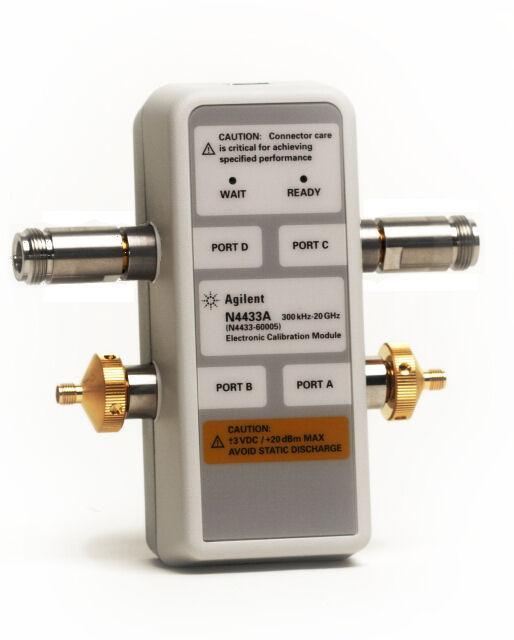
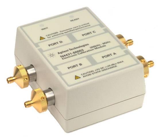
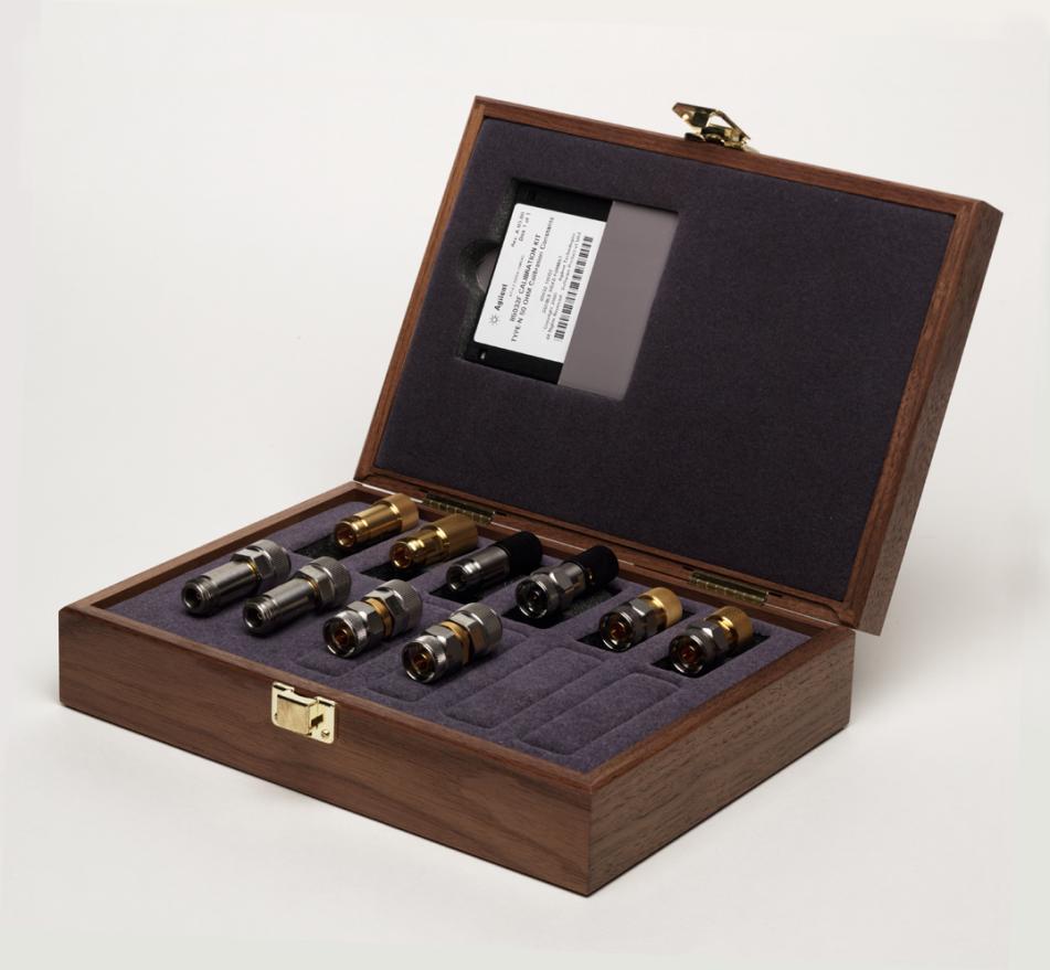
40 Calibration Kit 40
41 1. Calibrating Insertable Devices ZERO-LENGTH THRU What is an insertable device? has same type of connector, but different sex on each port has same type of sexless connector on each port (e.g. APC-7) DUT When doing a through cal, normally test ports mate directly cables can be connected directly without an adapter result is a zero-length through >Cal >Meas DUT Zero-Length Thru Cal: OK 41
42 2 Calibrating Non-Insertable Devices NO ZERO-LENGTH THRU What is a non-insertable device? has same connectors on each port (type and sex) has different type of connector on each port (e.g., waveguide on one port, coaxial on the other) DUT DUT What calibration choices do I have for non-insertable devices? Problem is with THRU cal, where: use an uncharacterized through adapter > Cal Adapter > Meas DUT But Adapter length isn t known measurement error! 42
43 Adapter Considerations reflection from adapter leakage signal desired signal r measured = Directivity + adapter + r r DUT Coupler directivity = 40 db Adapter DUT Termination DUT has SMA (f) connectors Worst-case System Directivity Adapting from APC-7 to SMA (m) APC-7 calibration done here 28 db APC-7 to SMA (m) SWR: db APC-7 to N (f) + N (m) to SMA (m) SWR:1.05 SWR: db APC-7 to N (m) + N (f) to SMA (f) + SMA (m) to (m) SWR:1.05 SWR:1.25 SWR:
44 Solution is... Characterized Adapter Port 1 Port 2 DUT DUT cannot be replaced by a Zero Length Thru during Calibration Characterized Port 1 Port 2 Thru adapter 1. Transmission cal using Characterized Thru (Thru characterized and CalKit definition changed) Port 1 Cal Std. Cal Std. Port 2 2. Reflection cal using CalKit(s) standards Port 1 Port 2 DUT 3. Measure DUT 2-Port Error corrected with uncertainty due to the Thru Std. 44
45 Calibration Kit Solutions Coaxial (*): - APC7 Agilent - N (50/75ohm) Agilent mm (SMA) Agilent mm Agilent - 1mm Agilent - BNC Maury Microwave - Automotive Fakra Rosenberger Balanced (*): - USB3.0 BitifEye - LAN - Automotive LVDS (adapters: Rosenberger (*) Full-2-Port (complete ad accurate) calibration procedure at Cal Plane 2 (DUT Plane) is possible only with a Calibration Kit with same mechanical configuration of the Device Under Test (eg. Fakra CalKit if DUT has Fakra connectors). Otherwise use Calibration Kit suitable for Cal Plane 1 and try to compensate the Adapters (good quality, low reflection is required) contribution between Cal Plane 1 and Cal Plane 2: - using De-Embedding, - using Port Extension. 45
46 Measurement Uncertainty I m able to: - calibrate the NA; - measure the DUT; - but what is the uncertainty of the value? After two-port calibration Uncorrected Value and Uncertainty START MHz STOP MHz 46


47 Uncertainties Calculator: UncertTest.xls - The Uncertainty Calculator helps you determine measurement uncertainty due to your vector network analyzer and calibration kit. - Inaccuracies introduced through cable movement, connector repeatability and temperature drift are not included. 47
48 48 S21 uncertainty (Magnitude)
49 49 S21 uncertainty (Phase)
")
50 S11 uncertainty (Magnitude) Linear2Log 50
51 LAB: Uncertainty value CH1 S 21 log MAG 10 db/ REF 0 db u 1 CH1 S 11 log MAG 5 db/ REF 0 db Cor u 4 u 2 u 3 START MHz STOP MHz CENTER MHz SPAN MHz Value and Uncertainty 51
52 52 Fixture Simulator function
53 > (Automatic) Port Extensions Apply both electrical delay and insertion loss to enhance port extensions First approach to give reasonable alternative to building in-fixture calibration standards or de-embedding fixture Only fixture mismatch remains as source of error (dominated by coaxial connector). Open or short placed at end of each transmission line Coaxial calibration reference planes Ports extended Measurement accuracy is increased by minimizing the reflection of the transition by using good quality connectors and having good 50-ohm transmission lines on the test fixture 53
.")
54 > De-Embedding Exclude undesired 2-port network from measured S-parameter Measured S-parameter Port 1 Undesired Network DUT Undesired Network Undesired Network Port 2 Port 3 De-embedded Response De-embedding ON/OFF is applied to all ports. Each port can be chosen as None or User. Undesired network is specified by Touchstone file (.s2p). 54
.")
55 > Embedding (Port Matching) Include matching network of each port into measured S-parameter Port 1 Matching Network Measured S-parameter DUT Matching Network Matching Network Port 2 Port 3 Embedded Response Port matching ON/OFF is applied to all ports. Matching network is defined by each port independently. Matching network is specified by pre-defined circuit models or Touchstone file (.s2p). 55
 can be defined for User.")
56 > Matching Circuit : Single-Ended models 0 for Series C means no capacitor. Touchstone file (.s2p) can be defined for User. 56

57 > Matching Circuit : Differential Measured S-parameter Port 2 Port 1 DUT Matching Network Embedded Response Port 3 57


58 > Characteristic Impedance Conversion Convert S-parameter measured with 50 ohms to arbitrary port characteristic impedance DUT DUT 50W 50W XW YW Port 1: 50W Port 2: 50W Port 1: 100W Port 2: 50W Impedance Conversion ON/OFF is applied to all ports. Port impedance can be specified at each port. Example: SAW filter Port 1 50W --> 100W Port 2 50W S11 on Log Mag & Smith 58

59 > Unbalanced to Balanced Conversion Convert single-ended S-parameter to mixed-mode S-parameter YW DUT XW XW YW Define device type Single-ended & Balanced Balanced & Balanced Single-ended, Single-ended & Balanced Assign physical ports to logical ports BalUn ON/OFF is applied to each trace. DUT Y/2W 2YW 59
60 60 Single-ended to Mixed-mode conversion
 Sdc11 S S S S DD11 DD21 CD11 CD21 S S S S DD12 DD22 CD12 CD22 S S S S DC11 DC 21 CC11 CC21 S S S S DC12 DC 22")
61 Mixed-Mode S-Parameters - Sdd11 is the differential Attenuation Sdd21 Scd21 Sdc21 Scc21 - Sdc11 is the LCL (Longitudinal Conversion Loss) Sdc11 S S S S DD11 DD21 CD11 CD21 S S S S DD12 DD22 CD12 CD22 S S S S DC11 DC 21 CC11 CC21 S S S S DC12 DC 22 CC12 CC22 61
62 Why Differential and Common Parameters? Needs filter 62
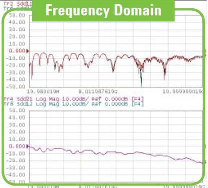
63 3. Measurement: Frequency Domain - Measurement Technique - Insertion Loss, Attenuation and Phase matching - Return Loss and Impedance - Cross Talk, FEXT, NEXT - Screening Attenuation 63
64 64 Measurement Technique: Frequency Sweep
65 65 Coaxial Cable Measurement: - Return Loss, Zin - Insertion Loss, Attenuation and Phase Matching

66 Coaxial Cable Measurement: > Return Loss Failure in manufacturing process LogMag format SWR format 66


67 Coaxial Cable Measurement: - Screening Attenuation To maximize Dynamic Range: - Decrease IFBW - Increase Source Power [external Amplifier] - If possible use Receiver s direct inputs Ref. Standards, Design & Installation of CATV-Cables, Bernhard Mund, bedea 67


68 68 Balanced Cable Measurement: - Insertion Loss, LCL - Return Loss, Zin

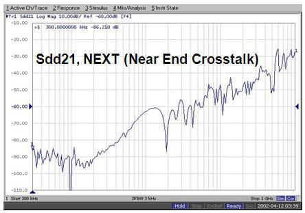
69 69 Balanced Cable Measurement: - CrossTalk, FEXT, NEXT

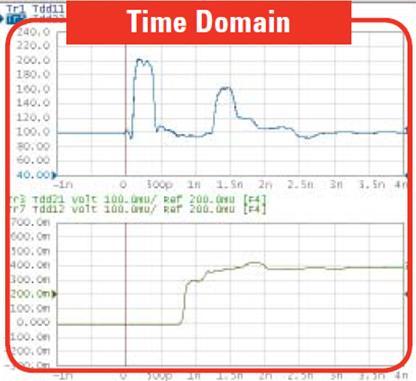
70 4. Measurement: Time Domain - Measurement Technique - Resolution and Range - Delay, Length and Velocity Factor - Gating 70
71 Time Domain on a Network Analyzer 71

72 TDR vs Network Analyzer sources 72
73 Why Time Domain? Frequency Domain Time Domain 73
74 Time Domain procedure 74
75 75 (1) Frequency Data: Resolution and Range
76 (1) Effect of Frequency Span on Resolution For Example (Return Loss meas, so /2): - Frequency Span = 1GHz - k =0.45 (TD mode and Window) - Velocity Factor = 0.66 (PE) Resolution (s) = 0.5ns Resolution (m) = 0.05m 76
77 (1) What is the Maximum Range that can be measured? For Example (Return Loss meas, so /2): - Frequency Span = 1GHz - # of points = Velocity Factor = 0.66 (PE) Range (s) = 100ns Range (m) = 19.8m 77
78 (2) Bandpass Mode 78

79 (2) Low Pass Mode 79
80 (2) Low Pass Step vs Impulse Inductor 80
81 (2) Low Pass modes with Impedance changes 81
82 (2) Summary on modes 82
 the frequency domain data prior to conversion to the time")
83 (3) Window Windowing improves the dynamic range of the time domain measurement by modifying (filtering) the frequency domain data prior to conversion to the time domain. 83
84 (3) Effect of Windows on Resolution: traces Response changes as window shape changes: (a) minimum window is best when higher resolution is needed to resolve signals with equivalent magnitudes, (b) maximum window is ideal for best dynamic range if responses are very different in magnitude. 84
85 (4) Gating Operation S11 S11 1 IFFT 2 Original Frequency Response Time Domain 4 S11 FFT 3 S11 Filter Out this Response Frequency Response w/ Gate Time Domain w/ Gate 85
86 (4) Gating Example: Time Domain response Connector Cable Connector Termination Remove the effects of the Input Connector S11 LIN 200 mu / REF -400 mu Gate On Cor START -1 ns STOP 9 ns 86
87 (5) Frequency Domain response with Gate On Connector Cable Connector Termination Gate Off S11 LIN 200 mu / REF -400 mu Gate On Cor START -1 ns STOP 9 ns Use Gating to show the frequency response of the output connector & termination only 87
88 88 > Coaxial cables with adapter and N connector

89 89 > Coaxial cable with adapter and Fakra connector

90 90 > Balanced cable with adapter and LVDS connector

91 91 Delay, Length and Velocity Factor

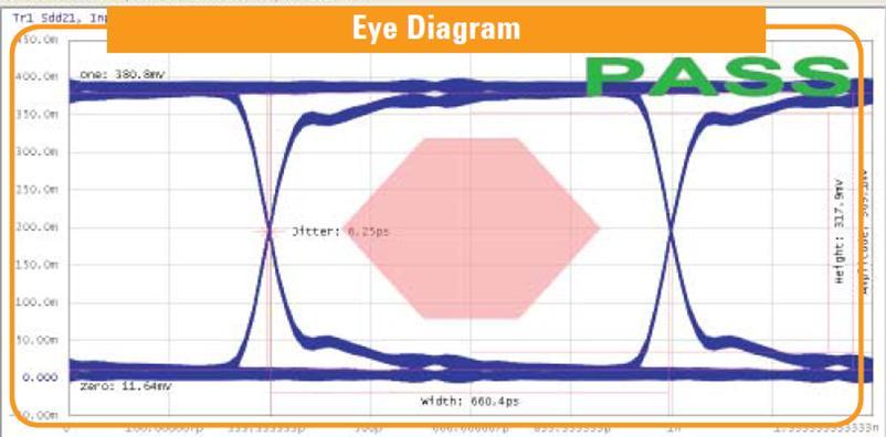
92 5. Measurement: Enhanced Time Domain (TDR) - Measurement Technique - Eye Diagram and Mask - Jitter, Emphasis, Equalization 92

93 93 Measurement Technique: Inverse Fourier Transform

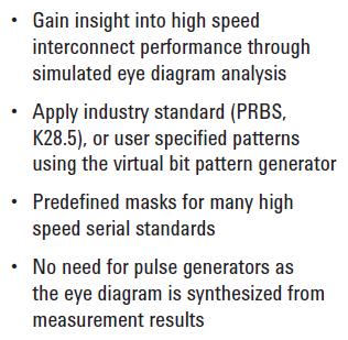
94 94 Eye Diagram and Mask

95 95 Jitter, Emphasis, Equalization
96 6. Labs - Frequency, Time and Enhanced Time with Coaxial cables and adapters - Frequency, Time and Enhanced Time with Balanced line 96
 with Coaxial cable and")
97 97 LAB1 Frequency, Time and Enhanced Time (TDR) with Coaxial cable and adapters
 with")
98 98 LAB2 Frequency, Time and Enhanced Time (TDR) with Balanced line
99 Q & A THE END 99
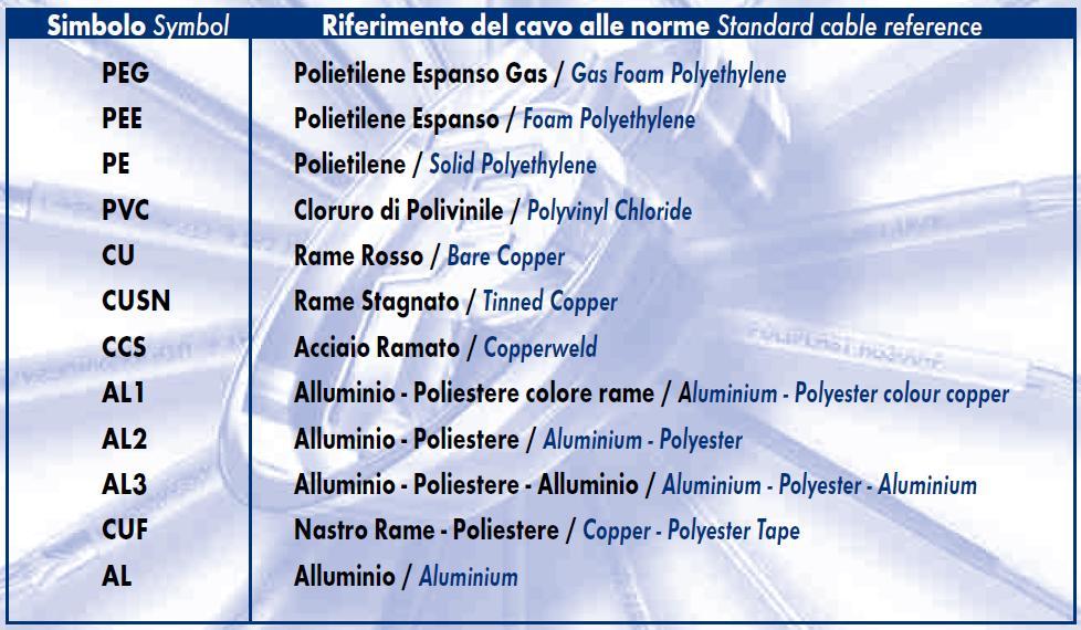
100 Dielectric 100
101 Balanced Cables and Connectors: LAN Name Type Bandwidth Applications Notes Cat3 UTP [6] 16 MHz [6] 10BASE-T and 100BASE- T4 Ethernet [6] Described in EIA/TIA-568. Unsuitable for speeds above 16 Mbit/s. Now mainly for telephone cables [6] Cat4 UTP [6] 20 MHz [6] 16 Mbit/s [6] Token Ring Not commonly used [6] Cat5 UTP [6] 100 MHz [6] Cat5e UTP [6] 100 MHz [6] 100BASE-TX & 1000BASE- T Ethernet [6] 100BASE-TX & 1000BASE- T Ethernet [6] Cat6 UTP [6] 250 MHz [6] 10GBASE-T Ethernet Common in most current LANs [6] Enhanced Cat5. Same construction as Cat5, but with better testing standards. Most commonly installed cable in Finland according to the 2002 standard. SFS-EN Cat6a 500 MHz 10GBASE-T Ethernet ISO/IEC 11801:2002 Amendment 2. Class F S/FTP [6] 600 MHz [6] Class Fa 1000 MHz Telephone, CCTV, 1000BASE-TX in the same cable. 10GBASE-T Ethernet. Telephone, CATV, 1000BASE-TX in the same cable. 10GBASE-T Ethernet. Four pairs, S/FTP (shielded pairs, braid-screened cable). Development complete - ISO/IEC nd Ed. Four pairs, S/FTP (shielded pairs, braid-screened cable). Development complete - ISO/IEC nd Ed. Am

102 Why VNA has Wider Dynamic Range? 102
June 2012 Agilent Technologies
 Perform Cable Test with a Network Analyzer: From Basic Measurement to Advanced Signal Integrity Measurements for Next Generation High Speed Serial Standards June 2012 Agilent Technologies Agenda 1. Device
Network Analysis Basics
 Adolfo Del Solar Application Engineer adolfo_del-solar@agilent.com MD1010 Network B2B Agenda Overview What Measurements do we make? Network Analyzer Hardware Error Models and Calibration Example Measurements
Agilent AN Applying Error Correction to Network Analyzer Measurements
 Agilent AN 287-3 Applying Error Correction to Network Analyzer Measurements Application Note 2 3 4 4 5 6 7 8 0 2 2 3 3 4 Table of Contents Introduction Sources and Types of Errors Types of Error Correction
Signal Integrity Testing with a Vector Network Analyzer. Neil Jarvis Applications Engineer
 Signal Integrity Testing with a Vector Network Analyzer Neil Jarvis Applications Engineer 1 Agenda RF Connectors A significant factor in repeatability and accuracy Selecting the best of several types for
Agilent ENA Series 2, 3 and 4 Port RF Network Analyzers
 gilent EN Series 2, 3 and 4 Port RF Network nalyzers 蔡明汎 gilent EO Project Manager (07)3377603 Email:ming-fan_tsai@agilent.com OTS:0800-047866 EN 1 genda What measurements do we make? Network nalyzer Hardware
Configuration of PNA-X, NVNA and X parameters
 Configuration of PNA-X, NVNA and X parameters VNA 1. S-Parameter Measurements 2. Harmonic Measurements NVNA 3. X-Parameter Measurements Introducing the PNA-X 50 GHz 43.5 GHz 26.5 GHz 13.5 GHz PNA-X Agilent
Keysight Technologies In-Fixture Measurements Using Vector Network Analyzers. Application Note
 Keysight Technologies In-Fixture Measurements Using Vector Network Analyzers Application Note Introduction This application note describes the use of vector network analyzers when making measurements of
application In-Fixture Measurements Using Vector Network Analyzers Network Analysis Solutions Application Note
 application Network Analysis Solutions In-Fixture Measurements Using Vector Network Analyzers Application Note 1287-9 Table of contents Introduction..................................................3 The
PLANAR 814/1. Vector Network Analyzer
 PLANAR 814/1 Vector Network Analyzer Frequency range: 100 khz 8 GHz Measured parameters: S11, S12, S21, S22 Wide output power range: -60 dbm to +10 dbm >150 db dynamic range (1 Hz IF bandwidth) Direct
Compact Series: S5065 & S5085 Vector Network Analyzers KEY FEATURES
 Compact Series: S5065 & S5085 Vector Network Analyzers KEY FEATURES Frequency range: 9 khz - 6.5 or 8.5 GHz Measured parameters: S11, S12, S21, S22 Wide output power adjustment range: -50 dbm to +5 dbm
FieldFox Handheld Education Series Part 3: Calibration Techniques for Precise Field Measurements
 FieldFox Handheld Education Series Part 3: Calibration Techniques for Precise Field Measurements FieldFox Handheld Education Series Interference Testing Cable and Antenna Measurements Calibration Techniques
Keysight MOI for USB Type-C Connectors & Cable Assemblies Compliance Tests (Type-C to Legacy Cable Assemblies)
") Revision 01.01 Jan-21, 2016 Universal Serial Bus Type-C TM Specification Revision 1.1 Keysight Method of Implementation (MOI) for USB Type-C TM Connectors and Cables Assemblies Compliance Tests Using Keysight
Revision 01.01 Jan-21, 2016 Universal Serial Bus Type-C TM Specification Revision 1.1 Keysight Method of Implementation (MOI) for USB Type-C TM Connectors and Cables Assemblies Compliance Tests Using Keysight
Chapter 12: Transmission Lines. EET-223: RF Communication Circuits Walter Lara
 Chapter 12: Transmission Lines EET-223: RF Communication Circuits Walter Lara Introduction A transmission line can be defined as the conductive connections between system elements that carry signal power.
Vector Network Analyzer
 Vector Network Analyzer VNA Basics VNA Roadshow Budapest 17/05/2016 Content Why Users Need VNAs VNA Terminology System Architecture Key Components Basic Measurements Calibration Methods Accuracy and Uncertainty
PLANAR S5048 and TR5048
 PLANAR S5048 and TR5048 Vector Network Analyzers KEY FEATURES Frequency range: 20 khz 4.8 GHz COM/DCOM compatible for LabView Measured parameters: and automation programming S11, S12, S21, S22 (S5048)
RF and Microwave Test and Design Roadshow 5 Locations across Australia and New Zealand
 RF and Microwave Test and Design Roadshow 5 Locations across Australia and New Zealand Advanced VNA Measurements Agenda Overview of the PXIe-5632 Architecture SW Experience Overview of VNA Calibration
Keysight MOI for USB Type-C Connectors & Cable Assemblies Compliance Tests (Type-C to Legacy Cable Assemblies)
") Revision 01.00 Nov-24, 2015 Universal Serial Bus Type-C TM Specification Revision 1.1 Keysight Method of Implementation (MOI) for USB Type-C TM Connectors and Cables Assemblies Compliance Tests Using Keysight
Revision 01.00 Nov-24, 2015 Universal Serial Bus Type-C TM Specification Revision 1.1 Keysight Method of Implementation (MOI) for USB Type-C TM Connectors and Cables Assemblies Compliance Tests Using Keysight
Vector Network Analyzers T - Series
 Datasheet Vector Network Analyzers T - Series Wide dynamic range 130 db typ. Low noise level < -120 dbm Low trace noise 1 mdb rms High measurement speed 125ms/point High effective directivity > 45 db Remote
Agilent Accurate Measurement of Packaged RF Devices. White Paper
 Agilent Accurate Measurement of Packaged RF Devices White Paper Slide #1 Slide #2 Accurate Measurement of Packaged RF Devices How to Measure These Devices RF and MW Device Test Seminar 1995 smafilt.tif
Reflectometer Series:
 Reflectometer Series: R54, R60 & R140 Vector Network Analyzers Clarke & Severn Electronics Ph +612 9482 1944 Email sales@clarke.com.au BUY NOW - www.cseonline.com.au KEY FEATURES Patent: US 9,291,657 No
Impedance 50 (75 connectors via adapters)
") VECTOR NETWORK ANALYZER PLANAR 304/1 DATA SHEET Frequency range: 300 khz to 3.2 GHz Measured parameters: S11, S21, S12, S22 Dynamic range of transmission measurement magnitude: 135 db Measurement time
VECTOR NETWORK ANALYZER PLANAR 304/1 DATA SHEET Frequency range: 300 khz to 3.2 GHz Measured parameters: S11, S21, S12, S22 Dynamic range of transmission measurement magnitude: 135 db Measurement time
PLANAR R54. Vector Reflectometer KEY FEATURES
 PLANAR R54 Vector Reflectometer KEY FEATURES Frequency range: 85 MHz 5.4 GHz Reflection coefficient magnitude and phase, cable loss, DTF Transmission coefficient magnitude when using two reflectometers
Bill Ham Martin Ogbuokiri. This clause specifies the electrical performance requirements for shielded and unshielded cables.
 098-219r2 Prepared by: Ed Armstrong Zane Daggett Bill Ham Martin Ogbuokiri Date: 07-24-98 Revised: 09-29-98 Revised again: 10-14-98 Revised again: 12-2-98 Revised again: 01-18-99 1. REQUIREMENTS FOR SPI-3
MWA REVB LNA Measurements
 1 MWA REVB LNA Measurements Hamdi Mani, Judd Bowman Abstract The MWA LNA (REVB) was measured on the Low Frequency Radio astronomy Lab using state of the art test equipment. S-parameters of the amplifier
Department of Electrical and Computer Engineering ECE332. Lab 3: High Frequency Measurements
 Department of Electrical and Computer Engineering ECE332 Version: 1.3.1 Revised: April 30, 2011 Contents 1 Pre-Lab Assignment 2 2 Introduction 2 2.1 Vector Network Analyzer.............................
Agilent Time Domain Analysis Using a Network Analyzer
 Agilent Time Domain Analysis Using a Network Analyzer Application Note 1287-12 0.0 0.045 0.6 0.035 Cable S(1,1) 0.4 0.2 Cable S(1,1) 0.025 0.015 0.005 0.0 1.0 1.5 2.0 2.5 3.0 3.5 4.0 Frequency (GHz) 0.005
Compact Series: S5048 & TR5048 Vector Network Analyzers KEY FEATURES
 Compact Series: S5048 & TR5048 Vector Network Analyzers KEY FEATURES Frequency range: 20 khz - 4.8 GHz Measured parameters: S11, S12, S21, S22 (S5048) S11, S21 (TR5048) Wide output power adjustment range:
Circuit Characterization with the Agilent 8714 VNA
 Circuit Characterization with the Agilent 8714 VNA By: Larry Dunleavy Wireless and Microwave Instruments University of South Florida Objectives 1) To examine the concepts of reflection, phase shift, attenuation,
EE290C - Spring 2004 Advanced Topics in Circuit Design
 EE290C - Spring 2004 Advanced Topics in Circuit Design Lecture #3 Measurements with VNA and TDR Ben Chia Tu-Th 4 5:30pm 531 Cory Agenda Relationships between time domain and frequency domain TDR Time Domain
There is a twenty db improvement in the reflection measurements when the port match errors are removed.
 ABSTRACT Many improvements have occurred in microwave error correction techniques the past few years. The various error sources which degrade calibration accuracy is better understood. Standards have been
Vector Network Analyzer Application note
 Vector Network Analyzer Application note Version 1.0 Vector Network Analyzer Introduction A vector network analyzer is used to measure the performance of circuits or networks such as amplifiers, filters,
Keysight Technologies Applying Error Correction to Vector Network Analyzer Measurements. Application Note
 Keysight Technologies Applying Error Correction to Vector Network Analyzer Measurements Application Note Introduction Only perfect test equipment would not need correction. Imperfections exist in even
Waveguide Calibration with Copper Mountain Technologies VNA
 Clarke & Severn Electronics Ph: +612 9482 1944 BUY NOW www.cseonline.com.au Introduction Waveguide components possess certain advantages over their counterpart devices with co-axial connectors: they can
772D coaxial dual-directional coupler 773D coaxial directional coupler. 775D coaxial dual-directional coupler 776D coaxial dual-directional coupler
 72 772D coaxial dual-directional coupler 773D coaxial directional coupler 775D coaxial dual-directional coupler 776D coaxial dual-directional coupler 777D coaxial dual-directional coupler 778D coaxial
Keysight Technologies Techniques for Advanced Cable Testing
 Keysight Technologies Techniques for Advanced Cable Testing Using FieldFox handheld analyzers Application Note Transmission lines are used to guide the flow of energy from one point to another. Line types
TEST EQUIPMENT PLUS. Signal Hound USB-SA44B / USB-TG44A. Application Note 1: The Smith Chart. Rev. 0
 Rev. 0 TEST EQUIPMENT PLUS Signal Hound USB-SA44B / USB-TG44A Application Note 1: The Smith Chart USING THE SMITH CHART Chapter 1 1 Using the Smith Chart Making Single-Frequency Vector Impedance Measurements
Limitations And Accuracies Of Time And Frequency Domain Analysis Of Physical Layer Devices
 Limitations And Accuracies Of Time And Frequency Domain Analysis Of Physical Layer Devices Outline Short Overview Fundamental Differences between TDR & Instruments Calibration & Normalization Measurement
NATIONAL UNIVERSITY of SINGAPORE
 NATIONAL UNIVERSITY of SINGAPORE Faculty of Engineering Electrical & Computer Engineering Department EE3104 Introduction to RF and Microwave Systems & Circuits Experiment 1 Familiarization on VNA Calibration
Aries Kapton CSP socket
 Aries Kapton CSP socket Measurement and Model Results prepared by Gert Hohenwarter 5/19/04 1 Table of Contents Table of Contents... 2 OBJECTIVE... 3 METHODOLOGY... 3 Test procedures... 4 Setup... 4 MEASUREMENTS...
Introduction to On-Wafer Characterization at Microwave Frequencies
 Introduction to On-Wafer Characterization at Microwave Frequencies Chinh Doan Graduate Student University of California, Berkeley Introduction to On-Wafer Characterization at Microwave Frequencies Dr.
ECE 4265/6265 Laboratory Project 7 Network Analyzer Calibration
 ECE 4265/6265 Laboratory Project 7 Network Analyzer Calibration Objectives The purpose of this lab is to introduce the concepts of calibration and error correction for microwave s-parameter measurements.
PLANAR 804/1. Vector Network Analyzer
 PLANAR 804/1 Vector Network Analyzer Frequency range: 100 khz 8 GHz Measured parameters: S11, S12, S21, S22 Wide output power range: -60 dbm to +10 dbm >145 db dynamic range (1 Hz IF bandwidth) Time domain
Custom Interconnects Fuzz Button with Hardhat Test Socket/Interposer 1.00 mm pitch
 Custom Interconnects Fuzz Button with Hardhat Test Socket/Interposer 1.00 mm pitch Measurement and Model Results prepared by Gert Hohenwarter 12/14/2015 1 Table of Contents TABLE OF CONTENTS...2 OBJECTIVE...
EXPERIMENT EM3 INTRODUCTION TO THE NETWORK ANALYZER
 ECE 351 ELECTROMAGNETICS EXPERIMENT EM3 INTRODUCTION TO THE NETWORK ANALYZER OBJECTIVE: The objective to this experiment is to introduce the student to some of the capabilities of a vector network analyzer.
Platform Migration 8510 to PNA. Graham Payne Application Engineer Agilent Technologies
 Platform Migration 8510 to PNA Graham Payne Application Engineer Agilent Technologies We set the standard... 8410 8510 When we introduced the 8510, we changed the way S-parameter measurements were made!
RF Characterization Report
 SMA-J-P-H-ST-MT1 Mated with: RF316-01SP1-01BJ1-0305 Description: 50-Ω SMA Board Mount Jack, Mixed Technology Samtec, Inc. 2005 All Rights Reserved Table of Contents Introduction...1 Product Description...1
Measurements with Scattering Parameter By Joseph L. Cahak Copyright 2013 Sunshine Design Engineering Services
 Measurements with Scattering Parameter By Joseph L. Cahak Copyright 2013 Sunshine Design Engineering Services Network Analyzer Measurements In many RF and Microwave measurements the S-Parameters are typically
ME1000 RF Circuit Design. Lab 4. Filter Characterization using Vector Network Analyzer (VNA)
") ME1000 RF Circuit Design Lab 4 Filter Characterization using Vector Network Analyzer (VNA) This courseware product contains scholarly and technical information and is protected by copyright laws and international
ME1000 RF Circuit Design Lab 4 Filter Characterization using Vector Network Analyzer (VNA) This courseware product contains scholarly and technical information and is protected by copyright laws and international
Aries Center probe CSP socket Cycling test
 Aries Center probe CSP socket Cycling test RF Measurement Results prepared by Gert Hohenwarter 10/27/04 1 Table of Contents TABLE OF CONTENTS... 2 OBJECTIVE... 3 METHODOLOGY... 3 Test procedures... 5 Setup...
Validation & Analysis of Complex Serial Bus Link Models
 Validation & Analysis of Complex Serial Bus Link Models Version 1.0 John Pickerd, Tektronix, Inc John.J.Pickerd@Tek.com 503-627-5122 Kan Tan, Tektronix, Inc Kan.Tan@Tektronix.com 503-627-2049 Abstract
PNA Family Microwave Network Analyzers (N522x/3x/4xB) CONFIGURATION GUIDE
 CONFIGURATION GUIDE") PNA Family Microwave Network Analyzers (N522x/3x/4xB) CONFIGURATION GUIDE Table of Contents PNA Family Network Analyzer Configurations... 05 Test set and power configuration options...05 Hardware options...
PNA Family Microwave Network Analyzers (N522x/3x/4xB) CONFIGURATION GUIDE Table of Contents PNA Family Network Analyzer Configurations... 05 Test set and power configuration options...05 Hardware options...
High Speed Characterization Report
 QTH-030-01-L-D-A Mates with QSH-030-01-L-D-A Description: High Speed Ground Plane Header Board-to-Board, 0.5mm (.0197 ) Pitch, 5mm (.1969 ) Stack Height Samtec, Inc. 2005 All Rights Reserved Table of Contents
EXTEND YOUR REACH GHz 60-90GHz GHz
 EXTEND YOUR REACH 50-75 GHz 60-90GHz 75-110 GHz Extend Your Reach Farran Technology and Copper Mountain Technologies, globally recognized innovators, with a combined 50 years experience in RF test and
Challenges and Solutions for Removing Fixture Effects in Multi-port Measurements
 DesignCon 2008 Challenges and Solutions for Removing Fixture Effects in Multi-port Measurements Robert Schaefer, Agilent Technologies schaefer-public@agilent.com Abstract As data rates continue to rise
Advanced Test Equipment Rentals ATEC (2832)
") Established 1981 Advanced Test Equipment Rentals www.atecorp.com 800-404-ATEC (2832) Agilent 2-Port and 4-Port PNA-X Network Analyzer N5249A - 10 MHz to 8.5 GHz N5241A - 10 MHz to 13.5 GHz N5242A - 10
Established 1981 Advanced Test Equipment Rentals www.atecorp.com 800-404-ATEC (2832) Agilent 2-Port and 4-Port PNA-X Network Analyzer N5249A - 10 MHz to 8.5 GHz N5241A - 10 MHz to 13.5 GHz N5242A - 10
High Speed Characterization Report
 SSW-1XX-22-X-D-VS Mates with TSM-1XX-1-X-DV-X Description: Surface Mount Terminal Strip,.1 [2.54mm] Pitch, 13.59mm (.535 ) Stack Height Samtec, Inc. 25 All Rights Reserved Table of Contents Connector Overview...
For EECS142, Lecture presented by Dr. Joel Dunsmore. Slide 1 Welcome to Network Analyzer Basics.
 For EECS142, Lecture presented by Dr. Joel Dunsmore Slide 1 Welcome to Network Analyzer Basics. Slide 2 One of the most fundamental concepts of high-frequency network analysis involves incident, reflected
Aries Kapton CSP socket Cycling test
 Aries Kapton CSP socket Cycling test RF Measurement Results prepared by Gert Hohenwarter 10/21/04 1 Table of Contents TABLE OF CONTENTS... 2 OBJECTIVE... 3 METHODOLOGY... 3 Test procedures... 5 Setup...
TEST & MEASURING INSTRUMENTS. Analyzer. (4 Ports) 4 Ports
 4 Ports") TEST & MEASURING INSTRUMENTS Analyzer (4 Ports) 4 Ports Key Features Frequrncy Range : 100kHz ~ 8GHz, 16 Parameters support (S11 ~ S44) Measurement time per point : 100us per point Wide Output Power Range
TEST & MEASURING INSTRUMENTS Analyzer (4 Ports) 4 Ports Key Features Frequrncy Range : 100kHz ~ 8GHz, 16 Parameters support (S11 ~ S44) Measurement time per point : 100us per point Wide Output Power Range
1000BASE-T1 EMC Test Specification for Common Mode Chokes
 IEEE 1000BASE-T1 EMC Test Specification for Common Mode Chokes Version 1.0 Author & Company Dr. Bernd Körber, FTZ Zwickau Title 1000BASE-T1 EMC Test Specification for Common Mode Chokes Version 1.0 Date
Advanced Product Design & Test for High-Speed Digital Devices
 Advanced Product Design & Test for High-Speed Digital Devices Presenters Part 1-30 min. Hidekazu Manabe Application Marketing Engineer Agilent Technologies Part 2-20 min. Mike Engbretson Chief Technology
The Practical Limitations of S Parameter Measurements and the Impact on Time- Domain Simulations of High Speed Interconnects
 The Practical Limitations of S Parameter Measurements and the Impact on Time- Domain Simulations of High Speed Interconnects Dennis Poulin Anritsu Company Slide 1 Outline PSU Signal Integrity Symposium
USB 3.1 Cable-Connector Assembly Compliance Tests. Test Solution Overview Using the Keysight E5071C ENA Option TDR. Last Update 2015/02/06
 USB 3.1 Cable-Connector Assembly s Test Solution Overview Using the Keysight E5071C ENA Option TDR Last Update 015/0/06 Purpose This slide will show how to make measurements of USB 3.1 cable & connector
Signal Integrity Tips and Techniques Using TDR, VNA and Modeling. Russ Kramer O.J. Danzy
 Signal Integrity Tips and Techniques Using TDR, VNA and Modeling Russ Kramer O.J. Danzy Simulation What is the Signal Integrity Challenge? Tx Rx Channel Asfiakhan Dreamstime.com - 3d People Communication
Calibration and De-Embedding Techniques in the Frequency Domain
 Calibration and De-Embedding Techniques in the Frequency Domain Tom Dagostino tom@teraspeed.com Alfred P. Neves al@teraspeed.com Page 1 Teraspeed Labs Teraspeed Consulting Group LLC 2008 Teraspeed Consulting
Transmission Line Theory and Advanced Measurements in the Field
 Transmission Line Theory and Advanced Measurements in the Field Co-sponsored by Tom Hoppin Application Specialist On Contract to Component Test Division Keysight Technologies Keysight Technologies 2015
Keysight Technologies Techniques for Precise Cable and Antenna Measurements in the Field
 Keysight Technologies Techniques for Precise Cable and Antenna Measurements in the Field Using FieldFox handheld analyzers Application Note This application note introduces the practical aspects of cable
Understanding the Fundamental Principles of Vector Network Analysis. Application Note
 Understanding the Fundamental Principles of Vector Network Analysis Application Note Table of Contents Introduction... 3 Measurements in Communications Systems... 3 Importance of Vector Measurements...
High Speed Characterization Report
 HLCD-20-XX-TD-BD-2 Mated with: LSHM-120-XX.X-X-DV-A Description: 0.50 mm Razor Beam High Speed Hermaphroditic Coax Cable Assembly Samtec, Inc. 2005 All Rights Reserved Table of Contents Cable Assembly
EFFECT OF SHIELDING ON CABLE RF INGRESS MEASUREMENTS LARRY COHEN
 EFFECT OF SHIELDING ON CABLE RF INGRESS MEASUREMENTS LARRY COHEN OVERVIEW Purpose: Examine the common-mode and differential RF ingress levels of 4-pair UTP, F/UTP, and F/FTP cables at an (RJ45) MDI port
Migrating 4195A to E5061B LF-RF Network Analyzer. April 2010 Agilent Technologies
 Migrating 4195A to E61B LF-RF Network Analyzer April 2010 Agilent Technologies Page 1 Contents Overview of 4195A to E61B migration Migrating 4195A to E61B in network measurements Migrating 4195A to E61B
High Speed Characterization Report
 ECDP-16-XX-L1-L2-2-2 Mated with: HSEC8-125-XX-XX-DV-X-XX Description: High-Speed 85Ω Differential Edge Card Cable Assembly, 30 AWG ACCELERATE TM Twinax Cable Samtec, Inc. 2005 All Rights Reserved Table
Determination of Uncertainty for Dielectric Properties Determination of Printed Circuit Board Material
 Determination of Uncertainty for Dielectric Properties Determination of Printed Circuit Board Material Marko Kettunen, Kare-Petri Lätti, Janne-Matti Heinola, Juha-Pekka Ström and Pertti Silventoinen Lappeenranta
High Speed Characterization Report
 ESCA-XX-XX-XX.XX-1-3 Mated with: SEAF8-XX-05.0-X-XX-2-K SEAM8-XX-S02.0-X-XX-2-K Description: 0.80 mm SEARAY High-Speed/High-Density Array Cable Assembly, 34 AWG Samtec, Inc. 2005 All Rights Reserved Table
Wafer-Level Calibration & Verification up to 750 GHz. Choon Beng Sia, Ph.D. Mobile:
 Wafer-Level Calibration & Verification up to 750 GHz Choon Beng Sia, Ph.D. Email: Choonbeng.sia@cmicro.com Mobile: +65 8186 7090 2016 Outline LRRM vs SOLT Calibration Verification Over-temperature RF calibration
Agilent Network Analysis Applying the 8510 TRL Calibration for Non-Coaxial Measurements. Product Note A
 Agilent Network Analysis Applying the 8510 TRL Calibration for Non-Coaxial Measurements Product Note 8510-8A Introduction This note describes how the Agilent 8510 network analyzer can be used to make error-corrected
Amateur Extra Manual Chapter 9.4 Transmission Lines
 9.4 TRANSMISSION LINES (page 9-31) WAVELENGTH IN A FEED LINE (page 9-31) VELOCITY OF PROPAGATION (page 9-32) Speed of Wave in a Transmission Line VF = Velocity Factor = Speed of Light in a Vacuum Question
Aries CSP microstrip socket Cycling test
 Aries CSP microstrip socket Cycling test RF Measurement Results prepared by Gert Hohenwarter 2/18/05 1 Table of Contents TABLE OF CONTENTS... 2 OBJECTIVE... 3 METHODOLOGY... 3 Test procedures... 6 Setup...
S3602C Vector Network Analyzer Datasheet
 S3602C Vector Network Analyzer Datasheet Saluki Technology Inc. The document applies to the vector network analyzers of the following models: S3602C vector network analyzer (10MHz - 43.5GHz). Options of
Application Note 5525
 Using the Wafer Scale Packaged Detector in 2 to 6 GHz Applications Application Note 5525 Introduction The is a broadband directional coupler with integrated temperature compensated detector designed for
Millimeter Signal Measurements: Techniques, Solutions and Best Practices
 New Network Analyzer platform Millimeter Signal Measurements: Techniques, Solutions and Best Practices Phase Noise measurements update 1 N522XA PNA Series Network Analyzer Introducing Highest Performance
Grundlagen der Impedanzmessung
 Grundlagen der Impedanzmessung presented by Michael Benzinger Application Engineer - RF & MW Agenda Impedance Measurement Basics Impedance Basics Impedance Dependency Factors Impedance Measurement Methods
Aries QFP microstrip socket
 Aries QFP microstrip socket Measurement and Model Results prepared by Gert Hohenwarter 2/18/05 1 Table of Contents Table of Contents... 2 OBJECTIVE... 3 METHODOLOGY... 3 Test procedures... 4 Setup... 4
Advanced Signal Integrity Measurements of High- Speed Differential Channels
 Advanced Signal Integrity Measurements of High- Speed Differential Channels September 2004 presented by: Mike Resso Greg LeCheminant Copyright 2004 Agilent Technologies, Inc. What We Will Discuss Today
High Speed Characterization Report
 PCRF-064-XXXX-EC-SMA-P-1 Mated with: PCIE-XXX-02-X-D-TH Description: PCI Express Cable Assembly, Low Loss Microwave Cable Samtec, Inc. 2005 All Rights Reserved Table of Contents Cable Assembly Overview...
Network Analyzer Basics
 Network Analysis is NOT. Router Bridge Repeater Hub Your IEEE 802.3 X.25 ISDN switched-packet data stream is running at 147 MBPS with -9 a BER of 1.523 X 10... What Types of Devices are Tested? Integration
High Speed Characterization Report
 ERCD_020_XX_TTR_TED_1_D Mated with: ERF8-020-05.0-S-DV-L Description: 0.8mm Edge Rate High Speed Coax Cable Assembly Samtec, Inc. 2005 All Rights Reserved Table of Contents Cable Assembly Overview... 1
Keysight Technologies FieldFox Handheld Analyzers
 Keysight Technologies FieldFox Handheld Analyzers 4/6.5/9/14/18/26.5/32/44/50 GHz Data Sheet N9913A N9914A N9915A N9925A N9935A N9916A N9926A N9936A N9917A N9927A N9937A N9918A N9928A N9938A N9950A N9951A
Signal Integrity Basics
 Signal Integrity Basics By Anritsu Field Application Engineers TABLE OF CONTENTS 1.0 Bits, Bytes and Hertz 2.0 Eye Patterns 3.0 Pulse Composition 4.0 Common Causes of Pulse Distortion 5.0 Measurements
Agilent Technologies High-Definition Multimedia
 Agilent Technologies High-Definition Multimedia Interface (HDMI) Cable Assembly Compliance Test Test Solution Overview Using the Agilent E5071C ENA Option TDR Last Update 013/08/1 (TH) Purpose This slide
Keysight 2-Port and 4-Port PNA-X Network Analyzer
 Keysight 2-Port and 4-Port PNA-X Network Analyzer N5249A - 0 MHz to 8.5 GHz N524A - 0 MHz to 3.5 GHz N5242A - 0 MHz to 26.5 GHz Data Sheet and Technical Specifications Documentation Warranty THE MATERIAL
Physical Test Setup for Impulse Noise Testing
 Physical Test Setup for Impulse Noise Testing Larry Cohen Overview Purpose: Use measurement results for the EM coupling (Campbell) clamp to determine a stable physical test setup for impulse noise testing.
IEEE RTPGE Automotive Datalinks over Twisted Quad Cabling
 Automotive Datalinks over Twisted Quad Cabling T. Müller, G. Armbrecht, S. Kunz Rosenberger Hochfrequenztechnik GmbH & Co. KG Outline Automotive Datalinks over Twisted Quad Cabling Twisted Quad fundamentals
Keysight Technologies FieldFox Handheld Analyzers
 Keysight Technologies FieldFox Handheld Analyzers 4/6.5/9/14/18/26.5/32/44/50 GHz Data Sheet N9913A N9914A N9915A N9925A N9935A N9916A N9926A N9936A N9917A N9927A N9937A N9918A N9928A N9938A N9950A N9951A
MWA Antenna Impedance Measurements
 1 MWA Antenna Impedance Measurements Hamdi Mani, Judd Bowman Abstract we describe measurements of the differential output impedance of the MWA bowtie antenna. The data shows that the magnitude of the impedance
MICROWAVE MICROWAVE TRAINING BENCH COMPONENT SPECIFICATIONS:
 Microwave section consists of Basic Microwave Training Bench, Advance Microwave Training Bench and Microwave Communication Training System. Microwave Training System is used to study all the concepts of
University of Pennsylvania Department of Electrical and Systems Engineering ESE319
 University of Pennsylvania Department of Electrical and Systems Engineering ESE39 Laboratory Experiment Parasitic Capacitance and Oscilloscope Loading This lab is designed to familiarize you with some
Agilent PNA Series RF Network Analyzers
 Agilent PNA Series RF Network Analyzers Configuration Guide E8356A/E8801A/N3381A E8357A/E8802A/N3382A E8358A/E8803A/N3383A 300 khz to 3 GHz 300 khz to 6 GHz 300 khz to 9 GHz System configuration summary
PART III LABORATORY MANUAL. Electromagnetic Waves and Transmission Lines By Dr. Jayanti Venkataraman
 PART III LABORATORY MANUAL 202 Experiment I - Calibration of the Network Analyzer Objective: Calibrate the Network Analyzer for Transmission Procedure: (i) Turn the Power On (ii) Set the Frequency for
A True Differential Millimeter Wave System with Port Power Control. Presented by: Suren Singh
 A True Differential Millimeter Wave System with Port Power Control Presented by: Suren Singh Agenda Need for True Differential and RF Power Control Vector Network Analyzer RF Port Power Control Port Power