June 2012 Agilent Technologies
|
|
|
- Moses Wells
- 6 years ago
- Views:
Transcription


1 Perform Cable Test with a Network Analyzer: From Basic Measurement to Advanced Signal Integrity Measurements for Next Generation High Speed Serial Standards June 2012 Agilent Technologies
 6.")
2 Agenda 1. Device Under Test: Cables & Connectors 2. Instrument for cables testing: Network Analyzer 3. Measurement: Frequency Domain 4. Measurement: Time Domain 5. Measurement: Enhanced Time Domain (TDR) 6. Labs

")


3 Agenda (Device Under Test) Specific Connectors (Fakra) Standard Connector (SMA,2.4mm) Coaxial Cable No Connector Balanced Cable
 Frequency")


4 Agenda (Measurement modes) Frequency Domain Time Domain Enhanced Time Domain Common Measurement Parameters Zc, Attenuation, Capacitance Velocity of Propagation DC Resistance, Delay,Crosstalk,NEXT, FEXT

5 1. Device Under Test: Cables & Connectors - Cable Equivalent Circuit - Coaxial Cables and Connectors - Balanced Cables and Connectors - Cable Parameters - Cable Measurement Issues
6 Cable is a Transmission Line Transmission lines are needed to convey RF and microwave energy from one point to another with minimal loss. The transmission line can be represented as an infinite series of twoport elementary components. Resistance, Inductance, Capacitance and Admittance define Characteristic Impedance Z 0.

7 normalized values Transmission line Z o Z o determines relationship between voltage and current waves Z o is a function of physical dimensions and r Z o is usually a real impedance (e.g. 50 or 75 ohms) attenuation is lowest at 77 ohms ohm standard power handling capacity peaks at 30 ohms Characteristic impedance for coaxial airlines (ohms)

8 The Type N Connector DC to 18GHz N type 75ohm IS NOT compatible with N Type 50ohm

9 The Precision 3.5 mm Connector Air dielectric: is stable with temperature DC to 34GHz

10 The SMA Connector Usually teflon: this expands with temperature DC to 22GHz This pin is often the center wire of the semi-rigid cable
11 CONNECTOR TYPE RF Connector Chart SPECIFIED UPPER FREQUENCY TYPICAL MODING ACCURACY CONNECTOR TYPE MATEABLE WITH DIELECTRIC BNC 2 GHz 2.2 GHz M/F self PTFE SMC 7 GHz 10 GHz M/F self PTFE 7 mm (APC-7) 18GHz GHz SEXLESS self PTFE Type N 18 Ghz GHz M/F type N PTFE 3.5 mm (APC-3.5) 26.5 GHz GHz M/F SMA and K Air SMA (3.5 mm size) 26.5 GHz GHz M/F 3.5 mm and K PTFE 2.92 (K) Wiltron-Anritsu 40 GHz GHz M/F SMA and 3.5 mm Air 2.4 mm (APC-2.4) 50 GHz >50 GHz M/F V connector Air 1.85 mm 65 GHz >65 GHz M/F 2.4 mm and V Air Wiltron V-connector GHz >60 GHz M/F 2.4 mm and 1.85mm Air 1.00 mm (IEEE standard) 110 GHz >110 GHz M/F self Air 1.10 mm (Anritsu-Wiltron) 110 GHz >110 GHz M/F self Air
12 The Automotive Fakra Connector DC to 6GHz FachKReis Automobil (Automobile Expert Group)
13 b. Balanced Cables and Connectors A balanced line or balanced signal pair is a transmission line consisting of two conductors of the same type, each of which have equal impedances along their lengths and equal impedances to ground and to other circuits. The main advantage of the balanced line format is good rejection of external noise. Main disadvantage is the limited frequency coverage.


 A 1 0.")

14 Balanced Cables and Connectors: LAN Screened / Unshielded Twisted Pair Screened / Shielded Twisted Pair Class Category Max Frequency (MHz) A B 2 1 C 3 16 D: D:2002 5E 100 E EA 6A 500 F FA 7A 1000 Local Area Network


15 Balanced Cables and Connectors: USB From USB 2.0 to USB 3.0: more complex connector, cable and test (e.g. Cross Talk) Universal Serial Bus
16 Cable Parameters The two principle factors which cause Attenuation are: Loss of conductors (caused by high frequency film effect), Dielectric loss. The Capacitance (pf/m at 1kHz) of a cable is indicated by the properties of the dielectric (the amount of electric charge when a potential difference exists between the two. Is directly proportional to the regularity of the dielectric's properties (typical values is 67 pf/m for PE). In the case of coaxial cables it is: Propagation speed is the speed of which an electrical signal travels along a line of Transmission. Is the ratio between speed of propagation within the cable and the speed in open space (66% for PE, Solid PolyEthylene dielectric). Characteristic Impedance Zo has to be as uniform as possible. The quality of the conductor and the geometry of the cable are not constant, causing signal distortion and loss. Screening attenuation depends on the external conductor's characteristics, which prevents the exchange of electromagnetic waves between the cable and the external environment. The Return Loss or Structural Return Loss (SRL is a specialized measurement of return loss referenced to the cable impedance) parameter is the measurement of the cable's production accuracy (mainly: constant dielectric extrusion pressure and cooling control.
17 Cable Parameters using VNA - Attenuation is S21 FreqD - Return Loss is S11 FreqD. SRL. Characteristic Impedance Zo - Screening attenuation (coaxial) is S21 FreqD - Cross Talk (balanced) is S21 FreqD - Length, Propagation speed is S11 TimeD - 1kHz requires LCR Meter]
18 Cable Measurement Issues - Frequency Broadband - Long electrical length (from swept to stepped sweep) - Reflection path loss (reflection dynamic range) - Non-Insertable (requires adapters) - Non-standard impedances (requires conversion) - Balanced (requires phy/sim BalUn transformer)
 - S parameters -")
19 DUT RF 2. Instrument for cables testing: Network Analyzer - Block Diagram (sources, signal separation devices, receivers, analysis) - S parameters - Magnitude and Phase - Calibration (insertable, not-insertable, ) - Fixture Simulator function - Differential and Common Parameters (dd, dc, cc)
20 Network Analyzer Block Diagram
 S12 = reverse transmission coefficient (isolation) Remember, S-parameters are inherently complex, linear quantities.")
21 S parameters Completely characterize a two port device with four S-parameters S11 = forward reflection coefficient (input match) S22 = reverse reflection coefficient (output match) S21 = forward transmission coefficient (gain or loss) S12 = reverse transmission coefficient (isolation) Remember, S-parameters are inherently complex, linear quantities. However, we often express them in a log - magnitude format
22 S parameters INCIDENT S 21 TRANSMITTED REFLECTED S 11 Port 1 Port 2 DUT S 22 REFLECTED TRANSMITTED S 12 b 1 = S 11 a 1 + S 12 a 2 INCIDENT b 2 = S 21 a 1 + S 22 a 2
23 The Need For Calibration Why do we have to calibrate? It is impossible to make perfect hardware It would be extremely difficult and expensive to make hardware good enough to entirely eliminate the need for error correction How do we get accuracy? With vector-error-corrected calibration Not the same as the yearly instrument calibration What does calibration do for us? Removes the largest contributor to measurement uncertainty: systematic errors Provides best picture of true performance of DUT Systematic error
24 Measurement Error Modeling Systematic errors Due to imperfections in the analyzer and test setup Assumed to be time invariant (predictable) Generally, are largest sources or error Random errors Vary with time in random fashion (unpredictable) Main contributors: instrument noise, switch and connector repeatability Drift errors Due to system performance changing after a calibration has been done Primarily caused by temperature variation Errors: SYSTEMATIC Measured Data RANDOM DRIFT Unknown Device
 Source Mismatch Load Mismatch Six forward and six reverse error terms yields 12 error terms for two-port")
25 Systematic Measurement Errors R Directivity A Crosstalk B DUT Frequency response Reflection tracking (A/R) Transmission tracking (B/R) Source Mismatch Load Mismatch Six forward and six reverse error terms yields 12 error terms for two-port devices


26 What is Vector-Error Correction? Errors Vector-error correction Is a process for characterizing systematic error terms Measures known electrical standards Removes effects of error terms from subsequent measurements Electrical standards Can be mechanical or electronic Are often an open, short, load, and thru, but can be arbitrary impedances as well Measured Actual
 Twelve systematic error terms measured Usually requires 12 measurements on four known standards (SOLT) Standards defined in cal kit")
27 Using Known Standards to Correct for Systematic Errors 1-port calibration (reflection measurements) Only three systematic error terms measured Directivity, source match, and reflection tracking Full two-port calibration (reflection and transmission measurements) Twelve systematic error terms measured Usually requires 12 measurements on four known standards (SOLT) Standards defined in cal kit definition file Network analyzer contains standard cal kit definitions CAL KIT DEFINITION MUST MATCH ACTUAL CAL KIT USED! User-built standards must be characterized and entered into user cal-kit

28 Before and After A One-Port Calibration Data after 1-port calibration Data before 1-port calibration
29 Two-Port Error Correction Reverse model Port 1 Port 2 Forward model Port 1 E X Port 2 a 1 b 1 E L' S 11 A S 21 A E RT' S 22 E S' E D' A b 2 a 2 a 1 b 1 E D E S S 21 A S 11 S A 22 A E TT E L a 2 b 2 E TT' S 12 A E X' E D E S E RT E D' E S' E RT' E RT = fwd directivity = fwd source match = fwd reflection tracking = rev directivity = rev source match = rev reflection tracking E L E TT E X E L' E TT' E X' S 12 A = fwd load match = fwd transmission tracking = fwd isolation = rev load match = rev transmission tracking = rev isolation S11m ED S11 a S m E D S E E RT E S E m E X S 1 22 ' 21 12m E X ' ( )( ' ) L ( )( ) RT ' E TT E TT ' S m E D' S E m E D S E S E RT E S E L E m E X S ' 21 12m E X ' ( )( ' ) ' L ( )( ) RT ' E TT E TT ' S m E X S21 a 21 S22m E D ' ( )( 1 ( E E TT E S ' E L )) RT ' S m E D S 1 11 E m E D E S 1 22 ' S ' ( )( E RT E S ' ) E L ' E ( 21 m E X S )( 12m E X ) RT ' L E TT E TT ' Each actual S-parameter is a function of all four measured S-parameters Analyzer must make forward and reverse sweep to update any one S-parameter Luckily, you don't need to know these equations to use a network analyzers!!! 12 S12 a S22a S E ' S E ( m X )( 1 11m D ( E ' )) E TT ' E S E L RT S ' ( m E D S ' E )( m E D S ' ) ' ( )( ) E S E RT E RT ' S E L E m E X S m E X L E TT E TT ' S22m ' ( E D S )( 11 m E D S ' E ) ' ( )( ) E RT ' E S E 21 m E X S 12 m E X 1 L RT E TT E TT ' S ( m E 1 11 D S E m E D ' S E S E RT E S E L E m E X S m E X ' )( 1 22 ' ) ' L ( 21 )( 12 ) RT ' E TT E TT '

30 Response versus Two-Port Calibration Measuring filter insertion loss After two-port calibration After response calibration Uncorrected

31 ECal: Electronic Calibration Variety of two- and four-port modules cover 300 khz to 67 GHz Nine connector types available, 50 and 75 ohms Single-connection calibration dramatically reduces calibration time makes calibrations easy to perform minimizes wear on cables and standards eliminates operator errors Highly repeatable temperature-compensated characterized terminations provide excellent accuracy USB controlled Microwave modules use a transmission line shunted by PIN-diode switches in various combinations
: - USB3.0 BitifEye www.bitifeye.")
 (*) Full-2-Port (complete ad accurate) calibration procedure at Cal Plane 2 (DUT Plane) is possible only with a Calibration Kit with same mechanical configuration of the Device Under Test (eg.")
32 Calibration Kit Solutions Coaxial (*): - APC7 Agilent - N (50/75ohm) Agilent mm (SMA) Agilent mm Agilent - 1mm Agilent - BNC Maury Microwave - Automotive Fakra Rosenberger Balanced (*): - USB3.0 BitifEye - LAN - Automotive LVDS (adapters: Rosenberger (*) Full-2-Port (complete ad accurate) calibration procedure at Cal Plane 2 (DUT Plane) is possible only with a Calibration Kit with same mechanical configuration of the Device Under Test (eg. Fakra CalKit if DUT has Fakra connectors). Otherwise use Calibration Kit suitable for Cal Plane 1 and try to compensate the Adapters contribution between Cal Plane 1 and Cal Plane 2: - using De-Embedding, - using Port Extension.
33 Fixture Simulator function

34 > De-Embedding Exclude undesired 2-port network from measured S-parameter Measured S-parameter Port 1 Undesired Network DUT Undesired Network Undesired Network Port 2 Port 3 De-embedded Response De-embedding ON/OFF is applied to all ports. Each port can be chosen as None or User. Undesired network is specified by Touchstone file (.s2p).
.")
35 > Embedding (Port Matching) Include matching network of each port into measured S-parameter Port 1 Matching Network Measured S-parameter DUT Matching Network Matching Network Port 2 Port 3 Embedded Response Port matching ON/OFF is applied to all ports. Matching network is defined by each port independently. Matching network is specified by pre-defined circuit models or Touchstone file (.s2p).
 can be defined for User.")
36 > Matching Circuit : Single-Ended models 0 for Series C means no capacitor. Touchstone file (.s2p) can be defined for User.

37 > Matching Circuit : Differential Measured S-parameter Port 2 Port 1 DUT Matching Network Embedded Response Port 3


38 > Characteristic Impedance Conversion Convert S-parameter measured with 50 ohms to arbitrary port characteristic impedance DUT DUT 50W 50W XW YW Port 1: 50W Port 2: 50W Port 1: 100W Port 2: 50W Impedance Conversion ON/OFF is applied to all ports. Port impedance can be specified at each port. Example: SAW filter Port 1 50W --> 100W Port 2 50W S11 on Log Mag & Smith
39 Single-ended to Mixed-mode conversion
 Sdc11 S S S S DD11 DD21 CD11 CD21 S S S S DD12 DD22 CD12 CD22 S S S S DC11 DC 21 CC11 CC21 S S S S DC12 DC 22")
40 Mixed-Mode S-Parameters - Sdd11 is the differential Attenuation Sdd21 Scd21 Sdc21 Scc21 - Sdc11 is the LCL (Longitudinal Conversion Loss) Sdc11 S S S S DD11 DD21 CD11 CD21 S S S S DD12 DD22 CD12 CD22 S S S S DC11 DC 21 CC11 CC21 S S S S DC12 DC 22 CC12 CC22
41 3. Measurement: Frequency Domain - Measurement Technique - Insertion Loss, Attenuation and Phase matching - Return Loss and Impedance - Cross Talk, FEXT, NEXT - Screening Attenuation
42 Measurement Technique: Frequency Sweep

43 Coaxial Cable Measurement: - Return Loss, Zin - Insertion Loss, Attenuation and Phase Matching

44 Coaxial Cable Measurement: > Return Loss Failure in manufacturing process LogMag format SWR format


45 Coaxial Cable Measurement: - Screening Attenuation To maximize Dynamic Range: - Decrease IFBW - Increase Source Power [external Amplifier] - If possible use Receiver s direct inputs Ref. Standards, Design & Installation of CATV-Cables, Bernhard Mund, bedea


46 Balanced Cable Measurement: - Insertion Loss, LCL - Return Loss, Zin


47 Balanced Cable Measurement: - CrossTalk, FEXT, NEXT

48 4. Measurement: Time Domain - Measurement Technique - Resolution and Range - Delay, Length and Velocity Factor - Gating
49 What is time domain? useful for measuring impedance values along a transmission line and for evaluating a device problem (discontinuity) in time or distance. Time domain display provides a more intuitive and direct look at the device under test (DUT) characteristics and gives more meaningful information concerning the broadband response of a transmission system than other measuring techniques by showing the effect of each discontinuity as a function of time or distance. r Frequency Upper Limit r Time

50 TDR Time Domain Reflectometry Technology OSCILLOSCOPE 2 t Trigger Chan 1 t STEP / SNAP GENERATOR DIRECTIONAL COUPLER UNKNOWN
*dt 0 Integrate 1/s*F(s) TDR F -1 t f CH1 START 0 s STOP 1.")
51 TDR Basics Using a Network Analyzer Start with broadband frequency sweep (often requires microwave VNA) Use inverse-fourier transform to compute time-domain Resolution inversely proportionate to frequency span Time Domain Frequency Domain CH1 S 22 Re 50 mu/ REF 0 U F -1 Cor 20 GHz t f 6 GHz t F(t)*dt 0 Integrate 1/s*F(s) TDR F -1 t f CH1 START 0 s STOP 1.5 ns
52 Frequency Domain S 11 Response of Semi-rigid Coax Cable r Upper Limit Frequency
53 Time Domain S Response of Semi-rigid Coax Cable 11 r Time
54 (1) Frequency Data: Resolution and Range
: - Frequency Span = 1GHz - k =0.")
55 (1) Effect of Frequency Span on Resolution S11 LIN 200 mu / REF-600 mu 1: mU 0 s F Span = 1 GHz Cor F Span = 3 GHz START -2 ns Same Time Span STOP 2 ns F Span = 6 GHz For Example (Return Loss meas, so /2): - Frequency Span = 1GHz - k =0.45 (TD mode and Window) - Velocity Factor = 0.66 (PE) Resolution (s) = 0.5ns Resolution (m) = 0.05m
56 Resolution as a Function of Frequency Span (2)
57 (1) What is the Maximum Range that can be measured? For Example (Return Loss meas, so /2): - Frequency Span = 1GHz - # of points = Velocity Factor = 0.66 (PE) Range (s) = 100ns Range (m) = 19.8m

58 Time domain Modes
59 (2) Summary on modes
60 (4) Gating Operation S11 S11 1 IFFT 2 Original Frequency Response Time Domain 4 S11 FFT 3 S11 Filter Out this Response Frequency Response w/ Gate Time Domain w/ Gate
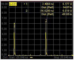
61 (4) Gating Example: Time Domain response Connector Cable Connector Termination Remove the effects of the Input Connector S11 LIN 200 mu / REF -400 mu Gate On Cor START -1 ns STOP 9 ns
62 (5) Frequency Domain response with Gate On Connector Cable Connector Termination Gate Off S11 LIN 200 mu / REF -400 mu Gate On Cor START -1 ns STOP 9 ns Use Gating to show the frequency response of the output connector & termination only

63 > Coaxial cables with adapter and N connector

64 > Coaxial cable with adapter and Fakra connector

65 > Balanced cable with adapter and LVDS connector

66 5. Measurement: Enhanced Time Domain (TDR) - Measurement Technique - Eye Diagram and Mask - Jitter, Emphasis, Equalization


67 What is ENA Option TDR? The ENA Option TDR is an application software embedded on the ENA, which provides an one-box solution for high speed serial interconnect analysis. Time Domain Frequency Domain 3 Breakthroughs for Signal Integrity Design and Verification Eye Diagram Simple and Intuitive Operation Fast and Accurate Measurements ESD protection inside ESD Robustness


68 One-box Solution for High Speed Serial Interconnect Analysis Time domain Time Domain Frequency Domain TDR Return Loss Frequency domain TDT Insertion Loss Eye diagram
69 One-box Solution for High Speed Serial Interconnect Analysis Time domain up to 9 markers Automatic display allocation for most common measurement parameters depending on selected device topology zoom Frequency domain Eye diagram rise time Dedicated controls for common adjustments Flexibility to set measurement parameter for each individual trace Set rise time to characterize expected performance at slower edge speeds Time (skew) measurements

70 One-box Solution for High Speed Serial Interconnect Analysis Time domain Eye Diagram Frequency domain Eye diagram

71 One-box Solution for High Speed Serial Interconnect Analysis Time domain Frequency domain Eye mask editor Eye mask test Eye diagram Virtual bit pattern generator Automated eye diagram measurement results
72 Three Breakthroughs for Signal Integrity Design and Verification Simple and Intuitive Similar look-and-feel to TDR scopes Intuitive operation even for users unfamiliar to vector network analyzers and S-parameter measurements. Fast and Accurate ESD Robustness ESD protection inside


73 Three Breakthroughs for Signal Integrity Design and Verification Simple and Intuitive Setup Wizard Guides the user through all of the required steps, making setup, error correction, and measurement intuitive and error-free. Fast and Accurate 4 steps!! ESD Robustness ESD protection inside


74 Three Breakthroughs for Signal Integrity Design and Verification Simple and Intuitive EDN (Oct 12, 2006) Fast and Accurate ESD Robustness ESD protection inside

75 Three Breakthroughs for Signal Integrity Design and Verification Simple and Intuitive DUT: 50 Ohm pattern Fast and Accurate ENA Option TDR TDR Scope 1 ohm/div 1 ohm/div ESD Robustness ESD protection inside VNA Based TDR measurements = Low Noise


76 Three Breakthroughs for Signal Integrity Design and Verification Simple and Intuitive DUT: 50 Ohm pattern Fast and Accurate ENA Option TDR TDR Scope 1 ohm/div Averaging 1 ohm/div ESD Robustness ESD protection inside Averaging can lower noise BUT


77 Three Breakthroughs for Signal Integrity Design and Verification Simple and Intuitive DUT: 50 Ohm pattern Fast and Accurate ENA Option TDR TDR Scopes 1 ohm/div Averaging 1 ohm/div ESD Robustness ESD protection inside Real-Time Analysis
78 Three Breakthroughs for Signal Integrity Design and Verification Simple and Intuitive Dynamic range is generally defined as the maximum power the receiver can accurately measure minus the receiver noise floor. Fast and Accurate ESD Robustness ESD protection inside E5071C Datasheet ( EN) July 10, 2009 System Dynamic Range 10Hz IFBW 86100C Technical Specifications ( EN) October 1, 2009 Attenuation Dynamic Range Internal


 available, but rise time is degraded.")
79 Three Breakthroughs for Signal Integrity Design and Verification Simple and Intuitive TDR Scopes Difficult to implement protection circuits inside the instrument without sacrificing performance. Fast and Accurate In addition, protection diodes cannot be placed in front of the sampling bridge as this would limit the bandwidth. This reduces the safe input voltage for a sampling oscilloscope to about 3 V, as compared to 500 V available on other oscilloscopes. Tektronix ApNote XYZ of Oscilloscopes, p17 (02/09, 03W ) ESD Robustness ESD protection inside External ESD protection module (80A02) available, but rise time is degraded. Single-channel protection and plugs into sampling mainframe $4K USD / module Reflected rise time when used with 80E04: 28ps -> 37ps


80 Three Breakthroughs for Signal Integrity Design and Verification Simple and Intuitive ENA Option TDR ESD protection circuits inside the instrument Fast and Accurate Higher robustness against ESD, because protection circuits are implemented inside the instrument for all ports, while maintaining excellent RF performance. ESD Robustness Proprietary ESD protection chip significantly increase ESD robustness, while at the same time maintaining excellent RF performance (22ps rise time for 20GHz models). ESD protection inside To ensure high robustness against ESD, ENA Option TDR is tested for ESD survival according to IEC801-2 Human Body Model.
81 Measurement Correlation TDR/TDT DUT: USB3.0 Cable 50 ps rise time (20-80%)


 Refer to")

82 Measurement Correlation Eye Diagram DUT: USB3.0 Cable PRBS 5 Gbps ENA Option TDR (simulated) N4903B C (live) Refer to Appendix for DisplayPort and SATA correlation data.


83 Summary The Agilent ENA Option TDR application Provides one-box solution for high speed serial interconnect analysis Time domain Frequency domain Eye diagram Brings three breakthroughs for signal integrity design and verification Simple & Intuitive Operation Fast & Accurate Measurements ESD Robustness
84 USB 3.0 Cable/Connector Compliance Test Solution
 PCI Special Interest Group (PCI-SIG ) Video Electronics Standards Association (VESA) Serial ATA")
 We re active in standards meetings, workshops, plugfests, and seminars Our customers test with highest confidence and achieve")
85 Agilent Digital Standards Program Our solutions are driven and supported by Agilent experts involved in international standards committees: Joint Electronic Devices Engineering Council (JEDEC) PCI Special Interest Group (PCI-SIG ) Video Electronics Standards Association (VESA) Serial ATA International Organization (SATA-IO) USB-Implementers Forum (USB-IF) Mobile Industry Processor Interface (MIPI) Alliance Optical Internetworking Forum (OIF) We re active in standards meetings, workshops, plugfests, and seminars Our customers test with highest confidence and achieve compliance faster
86 USB 3.0 Cable/Connector Compliance Test Solution Cable Assembly Host CabCon Device 2 SS USB Pair Full Simplex 2 SS USB Pair Full Simplex 2 USB 2.0 Pair Half-Duplex PWR (1), GND (1) SuperSpeeed USB Developers Conference Presentation, Taipei, Taiwan (April 1-2, 2010), SuperSpeed USB Physical Layer, Howard Heck, Intel Corporation

87 USB 3.0 Cable/Connector Compliance Test Solution Measurement Parameters Time Domain Measurements Mated Connector Impedance Cable Electrical Performance Characteristic Impedance Intra-pair Skew Near-end Crosstalk between SuperSpeed Pairs Differential Near-end Crosstalk between SuperSpeed Pairs Differential Crosstalk between D=/D- and SuperSpeed Pairs Frequency Domain Measurements Differential Insertion Loss (Sdd21) Differential to-common-mode Conversion (Scd21) SuperSpeeed USB Developers Conference Presentation, Taipei, Taiwan (April 1-2, 2010), SuperSpeed USB Physical Layer, Howard Heck, Intel Corporation


 Vector")


88 USB 3.0 Cable/Connector Compliance Test Solution Solution Overview USB 3.0 cable/connector compliance testing requires parametric measurements in both time and frequency domains Traditional Solution New Solution Frequency Domain Insertion Loss (Sdd21) Mode Conversion (Scd21) Vector Network Analyzer (VNA) ALL parameters can be measured with ENA Option TDR One-box Solution!! Time Domain Mated Connector Impedance Profile (TDR) Crosstalk (NEXT, FEXT) (TDT) TDR Scope


89 USB 3.0 Cable/Connector Compliance Test Solution Developers Conference (Taiwan, April 2010) ENA Option TDR introduced as recommended solution for CabCon compliance test. SuperSpeed USB Compliance: Overview, Rahman Ismail, Intel Corporation
 ECal Module N4431B for E5071C-480/485 N4433A for E5071C-4D5/4K5 Method of")
90 USB 3.0 Cable/Connector Compliance Test Solution ENA Option TDR Solution ENA Mainframe E5071C-480: 4-port, 9kHz to 8.5GHz E5071C-485: 4-port, 100kHz to 8.5GHz E5071C-4D5: 4-port, 300kHz to 14GHz E5071C-4K5: 4-port, 300kHz 20GHz Enhanced Time Domain Analysis Option (E5071C-TDR) ECal Module N4431B for E5071C-480/485 N4433A for E5071C-4D5/4K5 Method of Implementation (MOI) document available for download on Agilent.com State files (480,485,4D5, 4K5) and cal kit definition file for official cal fixtures are also available MOI (Method of Implementation) Step-by-step procedure on how to measure the specified parameters in the specification document using ENA Option TDR. SuperSpeed Cable Test Fixtures Fixtures for testing SuperSpeed cable assemblies and USB 3.0 connectors are available for purchase through Allion and BitifEye. usb/ssusbtools/
 Cable Z (Tdd11, Tdd22) Insertion Loss (Sdd21) Mode")
91 USB 3.0 Cable/Connector Compliance Test Solution Measurement Parameters Time Domain Frequency Domain Connector Z (Tdd11, Tdd22) Cable Z (Tdd11, Tdd22) Insertion Loss (Sdd21) Mode Conversion (Scd21) Intra-Pair Skew (T31, T42) D+/D- Intra-Pair Skew & Propagation Delay (T31, T42) Near End Xtalk D+/D- SS Xtalk (Tdd21) D+/D- Pair Attenuation (Sdd21)
 Similar look-and-feel to traditional TDR scopes, providing")
92 USB 3.0 Cable/Connector Compliance Test Solution Summary ENA Option TDR Cable/Connector Compliance Testing Solution is. One-box solution which provides complete characterization of high speed digital interconnects (time domain, frequency domain, eye diagram) Similar look-and-feel to traditional TDR scopes, providing simple and intuitive operation even for users unfamiliar to VNAs and S-parameters Adopted by test labs worldwide


93 High-Speed Digital Bus Compliance Test and Characterization Industry-leading Instruments + BitifEye Software Taking Test Automation to the Next Level Automated HDMI Cable Testing

94 HDMI Cable Test Station Agilent ENA-TDR and ECal, BitifEye Switch, Software ECal Module
95 HDMI Cable Test Station Agilent ENA-TDR and ECal, BitifEye Switch, Software Test Equipment (see Agilent HDMI Cable Test MOI): - Inlculded in BitifEye switch bundle - not needed with switch bundle - not needed with switch bundle - not needed with switch bundle - optional BitifEye switch bundle # 1x BIT , HDMI cable test switch matrix, 4x SMA Snap-On Connectors, 4x SMA cables 1 m - BitifEye test automation software # Bundle software BIT (new customers), upgrade product BIT (installed customer base)

 LabView, VEE, C#, VB, C++ Cable Test Software Cable Test BIT- -0450 New Sink Test Software HDMI Sink")

96 Test Integration N5990A Test Automation Software HDMI Compliance Test and Product Characterization Custom Solution Services Test Sequencer Legacy Code ValiFrame Test Automation Software Platform (Base Product, BIT ) User Programming (MS.NET dlls) LabView, VEE, C#, VB, C++ Cable Test Software Cable Test BIT New Sink Test Software HDMI Sink VF Opt. 150 Prot., HDCP VF Opt. 350 HEC, ARC VF Opt. 351 Source Test Software HDMI-Source N5399B Low Speed Test Low Speed VF Opt. 470) Instrument Software Standard Instruments Real-time Oscilloscope TMDS Sig. Generator Protocol Gen./Analyzer Pulse Arb Fct. Generator TDR, ENA Multi-, Volt-, LCR-meter investigation


97 Test Automation, System Integration N5990A Test Automation Software Overview Digital Bus Compliance Test and Characterization Customizations BitifEye and Partner Services; Support Test Sequencer N5990A Test Automation Software Platform Legacy Code, User Progr. Cable Test Software C, C++ C# Visual Basic VEE, LabView Python Opt. 500 Remote Interface (Opt. 2xx) TBT BIT- USB BIT- DP BIT- HDMI BIT- New BIT- Protocol/Ctrl/ HDCP Test MIPI MHL Remote Interface (Opt. 2xx) HDMI N5990A-350 Opt. 3xx Rx Test Software Rx PCIe N5990A-101 HDMI N5990A-150 Interface Opt. 2xx Tx Test Software USB U7243A N5990A-202 HDMI N5399B N5990A-250 Opt. 1xx Standard Instruments Pulse Data Generators AWGs BERTs Real-time Oscilloscopes Protocol Testers ENA-TDR


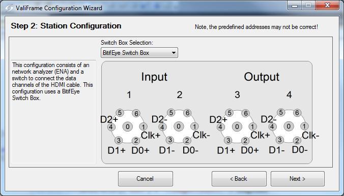
98 Automated HDMI Cable Test Details Station Configuration Examples

99 Automated HDMI Cable Test Details DUT Configuration

100 Automated HDMI Cable Test Details Calibration and Test Procedures Test 5-4: Intra-Pair Skew Test 5-5: Inter-Pair Skew Test 5-6: Far End Crosstalk Test 5-7: Attenuation and Phase Test 5-8: Differential Impedance User-selectable test parameters in Expert Mode!


101 Automated HDMI Cable Test Details Connection Diagram Examples

102 Automated HDMI Cable Test Details De-Embedding
103 Automated HDMI Cable Test Details De-Embedding De-embedding moves the measurement plane from the instrument connectors to the switch connectors; it compensates the impact caused by the switch Consists of two steps: 1. Calibrate the ENA-TDR for a single ended setup by using the ECal module 2. Measure the four paths of the module and save the de-embedding files. Once the files are saved, they are valid until the switch wears out or is replaced.


104 Automated HDMI Cable Test Coverage CTS Test Result Example


105 Automated HDMI Cable Test Coverage More CTS Test Result Examples
106 Resources Alexander Schmitt, Tel /

107 Questions?
108 References/backup slides

109 Agilent E5071C ENA Network Analyzer Portfolio Flexible Lineup for a Variety of Applications Select the number of ports, frequency, and bias tee to fit your application


110 Agilent E5071C ENA Network Analyzer Portfolio Protect your hardware investment The E5071C is a safe investment because of its flexibility. You can easily upgrade any feature of the E5071C whenever you need the feature! This includes not only software options like enhanced time domain mode, frequency offset mode, and MWA, but also hardware options such as frequency and number of testports. Buy the bandwidth you need today, upgrade to higher bandwidth in the future!!
Network Analysis Seminar. Cables measurement
 Network Analysis Seminar Cables measurement Agenda 1. Device Under Test: Cables & Connectors 2. Instrument for cables testing: Network Analyzer 3. Measurement: Frequency Domain 4. Measurement: Time Domain
Agilent Technologies High-Definition Multimedia
 Agilent Technologies High-Definition Multimedia Interface (HDMI) Cable Assembly Compliance Test Test Solution Overview Using the Agilent E5071C ENA Option TDR Last Update 013/08/1 (TH) Purpose This slide
USB 3.1 Cable-Connector Assembly Compliance Tests. Test Solution Overview Using the Keysight E5071C ENA Option TDR. Last Update 2015/02/06
 USB 3.1 Cable-Connector Assembly s Test Solution Overview Using the Keysight E5071C ENA Option TDR Last Update 015/0/06 Purpose This slide will show how to make measurements of USB 3.1 cable & connector
Advanced Product Design & Test for High-Speed Digital Devices
 Advanced Product Design & Test for High-Speed Digital Devices Presenters Part 1-30 min. Hidekazu Manabe Application Marketing Engineer Agilent Technologies Part 2-20 min. Mike Engbretson Chief Technology
Measuring Hot TDR and Eye Diagrams with an Vector Network Analyzer?
 Measuring Hot TDR and Eye Diagrams with an Vector Network Analyzer? Gustaaf Sutorius Application Engineer Agilent Technologies gustaaf_sutorius@agilent.com Page 1 #TDR fit in Typical Digital Development
Network Analysis Basics
 Adolfo Del Solar Application Engineer adolfo_del-solar@agilent.com MD1010 Network B2B Agenda Overview What Measurements do we make? Network Analyzer Hardware Error Models and Calibration Example Measurements
Keysight MOI for USB Type-C Connectors & Cable Assemblies Compliance Tests (Type-C to Legacy Cable Assemblies)
") Revision 01.01 Jan-21, 2016 Universal Serial Bus Type-C TM Specification Revision 1.1 Keysight Method of Implementation (MOI) for USB Type-C TM Connectors and Cables Assemblies Compliance Tests Using Keysight
Revision 01.01 Jan-21, 2016 Universal Serial Bus Type-C TM Specification Revision 1.1 Keysight Method of Implementation (MOI) for USB Type-C TM Connectors and Cables Assemblies Compliance Tests Using Keysight
Keysight MOI for USB Type-C Connectors & Cable Assemblies Compliance Tests (Type-C to Legacy Cable Assemblies)
") Revision 01.00 Nov-24, 2015 Universal Serial Bus Type-C TM Specification Revision 1.1 Keysight Method of Implementation (MOI) for USB Type-C TM Connectors and Cables Assemblies Compliance Tests Using Keysight
Revision 01.00 Nov-24, 2015 Universal Serial Bus Type-C TM Specification Revision 1.1 Keysight Method of Implementation (MOI) for USB Type-C TM Connectors and Cables Assemblies Compliance Tests Using Keysight
Agilent AN Applying Error Correction to Network Analyzer Measurements
 Agilent AN 287-3 Applying Error Correction to Network Analyzer Measurements Application Note 2 3 4 4 5 6 7 8 0 2 2 3 3 4 Table of Contents Introduction Sources and Types of Errors Types of Error Correction
MIPI S-parameter & Impedance Measurements with ENA Option TDR. Last update: 2014/04/08 (HK)
") MIPI S-parameter & Impedance Measurements with ENA Option TDR Last update: 2014/04/08 (HK) 1 MIPI Interfaces in a Mobile Platform 2 MIPI High Speed Physical, Protocol & App Layer Application Protocol Standard
MIPI S-parameter & Impedance Measurements with ENA Option TDR Last update: 2014/04/08 (HK) 1 MIPI Interfaces in a Mobile Platform 2 MIPI High Speed Physical, Protocol & App Layer Application Protocol Standard
Keysight Technologies In-Fixture Measurements Using Vector Network Analyzers. Application Note
 Keysight Technologies In-Fixture Measurements Using Vector Network Analyzers Application Note Introduction This application note describes the use of vector network analyzers when making measurements of
Agilent E5071C ENA Option TDR Enhanced Time Domain Analysis
 Agilent E5071C ENA TDR Enhanced Time Domain Analysis Technical Overview Eye diagram Time domain reflectometer Vector network analyzer One box solution for high speed serial interconnect analysis Simple
Configuration of PNA-X, NVNA and X parameters
 Configuration of PNA-X, NVNA and X parameters VNA 1. S-Parameter Measurements 2. Harmonic Measurements NVNA 3. X-Parameter Measurements Introducing the PNA-X 50 GHz 43.5 GHz 26.5 GHz 13.5 GHz PNA-X Agilent
High Speed Characterization Report
 PCRF-064-XXXX-EC-SMA-P-1 Mated with: PCIE-XXX-02-X-D-TH Description: PCI Express Cable Assembly, Low Loss Microwave Cable Samtec, Inc. 2005 All Rights Reserved Table of Contents Cable Assembly Overview...
application In-Fixture Measurements Using Vector Network Analyzers Network Analysis Solutions Application Note
 application Network Analysis Solutions In-Fixture Measurements Using Vector Network Analyzers Application Note 1287-9 Table of contents Introduction..................................................3 The
Compact Series: S5065 & S5085 Vector Network Analyzers KEY FEATURES
 Compact Series: S5065 & S5085 Vector Network Analyzers KEY FEATURES Frequency range: 9 khz - 6.5 or 8.5 GHz Measured parameters: S11, S12, S21, S22 Wide output power adjustment range: -50 dbm to +5 dbm
Overcome mmwave Component Test Challenges. Senior Project Manager / Keysight Technologies
 Overcome mmwave Component Test Challenges Senior Project Manager / Keysight Technologies Kenny Liao 2018.06.11 Taipei D I S C U S S I O N T O P I C S Millimeter Wave Component Application Space Millimeter
High Speed Characterization Report
 HLCD-20-XX-TD-BD-2 Mated with: LSHM-120-XX.X-X-DV-A Description: 0.50 mm Razor Beam High Speed Hermaphroditic Coax Cable Assembly Samtec, Inc. 2005 All Rights Reserved Table of Contents Cable Assembly
RF and Microwave Test and Design Roadshow 5 Locations across Australia and New Zealand
 RF and Microwave Test and Design Roadshow 5 Locations across Australia and New Zealand Advanced VNA Measurements Agenda Overview of the PXIe-5632 Architecture SW Experience Overview of VNA Calibration
High Speed Characterization Report
 ESCA-XX-XX-XX.XX-1-3 Mated with: SEAF8-XX-05.0-X-XX-2-K SEAM8-XX-S02.0-X-XX-2-K Description: 0.80 mm SEARAY High-Speed/High-Density Array Cable Assembly, 34 AWG Samtec, Inc. 2005 All Rights Reserved Table
High Speed Characterization Report
 ECDP-16-XX-L1-L2-2-2 Mated with: HSEC8-125-XX-XX-DV-X-XX Description: High-Speed 85Ω Differential Edge Card Cable Assembly, 30 AWG ACCELERATE TM Twinax Cable Samtec, Inc. 2005 All Rights Reserved Table
Agilent MOI for MIPI D-PHY Conformance Tests Revision 1.00 Dec-1, 2011
 Revision 1.00 Dec-1, 2011 Agilent Method of Implementation (MOI) for MIPI D-PHY Conformance Tests Using Agilent E5071C ENA Network Analyzer Option TDR 1 Table of Contents 1. Modification Record... 4 2.
Signal Integrity Tips and Techniques Using TDR, VNA and Modeling. Russ Kramer O.J. Danzy
 Signal Integrity Tips and Techniques Using TDR, VNA and Modeling Russ Kramer O.J. Danzy Simulation What is the Signal Integrity Challenge? Tx Rx Channel Asfiakhan Dreamstime.com - 3d People Communication
Reflectometer Series:
 Reflectometer Series: R54, R60 & R140 Vector Network Analyzers Clarke & Severn Electronics Ph +612 9482 1944 Email sales@clarke.com.au BUY NOW - www.cseonline.com.au KEY FEATURES Patent: US 9,291,657 No
PLANAR R54. Vector Reflectometer KEY FEATURES
 PLANAR R54 Vector Reflectometer KEY FEATURES Frequency range: 85 MHz 5.4 GHz Reflection coefficient magnitude and phase, cable loss, DTF Transmission coefficient magnitude when using two reflectometers
High Speed Characterization Report
 ERCD_020_XX_TTR_TED_1_D Mated with: ERF8-020-05.0-S-DV-L Description: 0.8mm Edge Rate High Speed Coax Cable Assembly Samtec, Inc. 2005 All Rights Reserved Table of Contents Cable Assembly Overview... 1
Keysight Technologies S93011A Enhanced Time Domain Analysis with TDR. Technical Overview
 Keysight Technologies S93011A Enhanced Time Domain Analysis with TDR Technical Overview 02 Keysight S93011A Enhanced Time Domain Analysis with TDR - Technical Overview One-box Solution For High-Speed Serial
High Speed Characterization Report
 QTH-030-01-L-D-A Mates with QSH-030-01-L-D-A Description: High Speed Ground Plane Header Board-to-Board, 0.5mm (.0197 ) Pitch, 5mm (.1969 ) Stack Height Samtec, Inc. 2005 All Rights Reserved Table of Contents
Keysight MOI for MIPI D-PHY Conformance Tests Revision Oct, 2014
 Revision 1.10 10-Oct, 2014 Keysight Method of Implementation (MOI) for MIPI D-PHY Conformance Tests Using Keysight E5071C ENA Network Analyzer Option TDR 1 Table of Contents 1. Modification Record... 4
PLANAR 814/1. Vector Network Analyzer
 PLANAR 814/1 Vector Network Analyzer Frequency range: 100 khz 8 GHz Measured parameters: S11, S12, S21, S22 Wide output power range: -60 dbm to +10 dbm >150 db dynamic range (1 Hz IF bandwidth) Direct
High Speed Characterization Report
 PCIEC-XXX-XXXX-EC-EM-P Mated with: PCIE-XXX-02-X-D-TH Description: 1.00 mm PCI Express Internal Cable Assembly, 30 AWG Twinax Ribbon Cable Samtec, Inc. 2005 All Rights Reserved Table of Contents Cable
Limitations And Accuracies Of Time And Frequency Domain Analysis Of Physical Layer Devices
 Limitations And Accuracies Of Time And Frequency Domain Analysis Of Physical Layer Devices Outline Short Overview Fundamental Differences between TDR & Instruments Calibration & Normalization Measurement
Impedance 50 (75 connectors via adapters)
") VECTOR NETWORK ANALYZER PLANAR 304/1 DATA SHEET Frequency range: 300 khz to 3.2 GHz Measured parameters: S11, S21, S12, S22 Dynamic range of transmission measurement magnitude: 135 db Measurement time
VECTOR NETWORK ANALYZER PLANAR 304/1 DATA SHEET Frequency range: 300 khz to 3.2 GHz Measured parameters: S11, S21, S12, S22 Dynamic range of transmission measurement magnitude: 135 db Measurement time
Agilent ENA Series 2, 3 and 4 Port RF Network Analyzers
 gilent EN Series 2, 3 and 4 Port RF Network nalyzers 蔡明汎 gilent EO Project Manager (07)3377603 Email:ming-fan_tsai@agilent.com OTS:0800-047866 EN 1 genda What measurements do we make? Network nalyzer Hardware
High Speed Characterization Report
 SSW-1XX-22-X-D-VS Mates with TSM-1XX-1-X-DV-X Description: Surface Mount Terminal Strip,.1 [2.54mm] Pitch, 13.59mm (.535 ) Stack Height Samtec, Inc. 25 All Rights Reserved Table of Contents Connector Overview...
9 khz to 4.5/6.5/8.5 GHz 100 khz to 4.5/6.5/8.5 GHz (with bias tees) 300 khz to 14/20 GHz (with bias tees)
 300 khz to 14/20 GHz (with bias tees)") Agilent E5071C ENA Network Analyzer 9 khz to 4.5/6.5/8.5 GHz 100 khz to 4.5/6.5/8.5 GHz () 300 khz to 14/20 GHz () The industry standard in RF network analysis ENA New Standards in Speed, Accuracy and
Agilent E5071C ENA Network Analyzer 9 khz to 4.5/6.5/8.5 GHz 100 khz to 4.5/6.5/8.5 GHz () 300 khz to 14/20 GHz () The industry standard in RF network analysis ENA New Standards in Speed, Accuracy and
Keysight Technologies E5071C ENA Option TDR Enhanced Time Domain Analysis. Technical Overview
 Keysight Technologies E5071C ENA Option TDR Enhanced Time Domain Analysis Technical Overview Introduction One box solution for high speed serial interconnect analysis Simple and Intuitive Operation Fast
Platform Migration 8510 to PNA. Graham Payne Application Engineer Agilent Technologies
 Platform Migration 8510 to PNA Graham Payne Application Engineer Agilent Technologies We set the standard... 8410 8510 When we introduced the 8510, we changed the way S-parameter measurements were made!
Advanced Test Equipment Rentals ATEC (2832)
") Established 1981 Advanced Test Equipment Rentals www.atecorp.com 800-404-ATEC (2832) Agilent 2-Port and 4-Port PNA-X Network Analyzer N5249A - 10 MHz to 8.5 GHz N5241A - 10 MHz to 13.5 GHz N5242A - 10
Established 1981 Advanced Test Equipment Rentals www.atecorp.com 800-404-ATEC (2832) Agilent 2-Port and 4-Port PNA-X Network Analyzer N5249A - 10 MHz to 8.5 GHz N5241A - 10 MHz to 13.5 GHz N5242A - 10
Signal Integrity Testing with a Vector Network Analyzer. Neil Jarvis Applications Engineer
 Signal Integrity Testing with a Vector Network Analyzer Neil Jarvis Applications Engineer 1 Agenda RF Connectors A significant factor in repeatability and accuracy Selecting the best of several types for
High Speed Characterization Report
 PCRF-064-1000-SMA-P-1 Mated with: PCIE-XXX-02-X-D-TH and SMA-J-P-X-ST-TH1 Description: Cable Assembly, Low Loss Microwave Coax, PCI Express Breakout Samtec, Inc. 2005 All Rights Reserved Table of Contents
Vector Network Analyzer Application note
 Vector Network Analyzer Application note Version 1.0 Vector Network Analyzer Introduction A vector network analyzer is used to measure the performance of circuits or networks such as amplifiers, filters,
PNA Family Microwave Network Analyzers (N522x/3x/4xB) CONFIGURATION GUIDE
 CONFIGURATION GUIDE") PNA Family Microwave Network Analyzers (N522x/3x/4xB) CONFIGURATION GUIDE Table of Contents PNA Family Network Analyzer Configurations... 05 Test set and power configuration options...05 Hardware options...
PNA Family Microwave Network Analyzers (N522x/3x/4xB) CONFIGURATION GUIDE Table of Contents PNA Family Network Analyzer Configurations... 05 Test set and power configuration options...05 Hardware options...
Vector Network Analysis
 Portfolio Brochure Vector Network Analysis Product Portfolio Vector Network Analysis VNA Innovation Timeline In 1965, Anritsu filed the patent that defined the first modern Vector Network Analyzer (VNA).
Agilent MOI for MIPI M-PHY Conformance Tests Revision Mar 2014
 Revision 1.10 20 Mar 2014 Agilent Method of Implementation (MOI) for MIPI M-PHY Conformance Tests Using Agilent E5071C ENA Network Analyzer Option TDR 1 Table of Contents 1. Modification Record... 4 2.
PLANAR S5048 and TR5048
 PLANAR S5048 and TR5048 Vector Network Analyzers KEY FEATURES Frequency range: 20 khz 4.8 GHz COM/DCOM compatible for LabView Measured parameters: and automation programming S11, S12, S21, S22 (S5048)
Agilent 4-Port PNA-L Network Analyzers
 Agilent 4-Port PNA-L Network Analyzers N5230A Options 240, 245 300 khz to 20 GHz Speed and accuracy you can count on Integrated 4-port, balanced measurements up to 20 GHz Introducing the 4-port PNA-L network
Improving TDR/TDT Measurements Using Normalization Application Note
 Improving TDR/TDT Measurements Using Normalization Application Note 1304-5 2 TDR/TDT and Normalization Normalization, an error-correction process, helps ensure that time domain reflectometer (TDR) and
Compact Series: S5048 & TR5048 Vector Network Analyzers KEY FEATURES
 Compact Series: S5048 & TR5048 Vector Network Analyzers KEY FEATURES Frequency range: 20 khz - 4.8 GHz Measured parameters: S11, S12, S21, S22 (S5048) S11, S21 (TR5048) Wide output power adjustment range:
Department of Electrical and Computer Engineering ECE332. Lab 3: High Frequency Measurements
 Department of Electrical and Computer Engineering ECE332 Version: 1.3.1 Revised: April 30, 2011 Contents 1 Pre-Lab Assignment 2 2 Introduction 2 2.1 Vector Network Analyzer.............................
Advanced Signal Integrity Measurements of High- Speed Differential Channels
 Advanced Signal Integrity Measurements of High- Speed Differential Channels September 2004 presented by: Mike Resso Greg LeCheminant Copyright 2004 Agilent Technologies, Inc. What We Will Discuss Today
Bill Ham Martin Ogbuokiri. This clause specifies the electrical performance requirements for shielded and unshielded cables.
 098-219r2 Prepared by: Ed Armstrong Zane Daggett Bill Ham Martin Ogbuokiri Date: 07-24-98 Revised: 09-29-98 Revised again: 10-14-98 Revised again: 12-2-98 Revised again: 01-18-99 1. REQUIREMENTS FOR SPI-3
Agilent. E5071C ENA Network Analyzer 9 khz to 4.5/6.5/8.5 GHz 100 khz to 4.5/6.5/8.5 GHz (with bias tees) 300 khz to 14/20 GHz (with bias tees)
 300 khz to 14/20 GHz (with bias tees)") Agilent E5071C ENA Network Analyzer 9 khz to 4.5/6.5/8.5 GHz 0 khz to 4.5/6.5/8.5 GHz (with bias tees) 300 khz to 14/20 GHz (with bias tees) E5091A Multiport Test Set E5092A Configurable Multiport Test
Agilent E5071C ENA Network Analyzer 9 khz to 4.5/6.5/8.5 GHz 0 khz to 4.5/6.5/8.5 GHz (with bias tees) 300 khz to 14/20 GHz (with bias tees) E5091A Multiport Test Set E5092A Configurable Multiport Test
Advanced Test Equipment Rentals ATEC (2832)
") Established 1981 Advanced Test Equipment Rentals www.atecorp.com 800-404-ATEC (2832) Agilent E5071C ENA Network Analyzer 9 khz to 4.5/6.5/8.5 GHz 100 khz to 4.5/6.5/8.5 GHz () 300 khz to 14/20 GHz () The
Established 1981 Advanced Test Equipment Rentals www.atecorp.com 800-404-ATEC (2832) Agilent E5071C ENA Network Analyzer 9 khz to 4.5/6.5/8.5 GHz 100 khz to 4.5/6.5/8.5 GHz () 300 khz to 14/20 GHz () The
Validation & Analysis of Complex Serial Bus Link Models
 Validation & Analysis of Complex Serial Bus Link Models Version 1.0 John Pickerd, Tektronix, Inc John.J.Pickerd@Tek.com 503-627-5122 Kan Tan, Tektronix, Inc Kan.Tan@Tektronix.com 503-627-2049 Abstract
Vector Network Analyzer
 Vector Network Analyzer VNA Basics VNA Roadshow Budapest 17/05/2016 Content Why Users Need VNAs VNA Terminology System Architecture Key Components Basic Measurements Calibration Methods Accuracy and Uncertainty
Agilent Correlation between TDR oscilloscope and VNA generated time domain waveform
 Agilent Correlation between TDR oscilloscope and VNA generated time domain waveform Application Note Introduction Time domain analysis (TDA) is a common method for evaluating transmission lines and has
Vector Network Analyzers T - Series
 Datasheet Vector Network Analyzers T - Series Wide dynamic range 130 db typ. Low noise level < -120 dbm Low trace noise 1 mdb rms High measurement speed 125ms/point High effective directivity > 45 db Remote
Keysight Technologies E5071C ENA Vector Network Analyzer. E5092A Configurable Multiport Test Set
 Keysight Technologies E5071C ENA Vector Network Analyzer 9 khz to 4.5/6.5/8.5 GHz 100 khz to 4.5/6.5/8.5 GHz (with bias tees) 300 khz to 14/20 GHz (with bias tees) E5092A Configurable Multiport Test Set
Agilent. E5071C ENA Network Analyzer 9 khz to 4.5/6.5/8.5 GHz 100 khz to 4.5/6.5/8.5 GHz (with bias tees) 300 khz to 14/20 GHz (with bias tees)
 300 khz to 14/20 GHz (with bias tees)") Agilent E571C ENA Network Analyzer 9 khz to 4.5/6.5/8.5 GHz khz to 4.5/6.5/8.5 GHz (with bias tees) 3 khz to 14/2 GHz (with bias tees) E592A Configurable Multiport Test Set Data Sheet Table of Contents
Agilent E571C ENA Network Analyzer 9 khz to 4.5/6.5/8.5 GHz khz to 4.5/6.5/8.5 GHz (with bias tees) 3 khz to 14/2 GHz (with bias tees) E592A Configurable Multiport Test Set Data Sheet Table of Contents
Agilent Time Domain Analysis Using a Network Analyzer
 Agilent Time Domain Analysis Using a Network Analyzer Application Note 1287-12 0.0 0.045 0.6 0.035 Cable S(1,1) 0.4 0.2 Cable S(1,1) 0.025 0.015 0.005 0.0 1.0 1.5 2.0 2.5 3.0 3.5 4.0 Frequency (GHz) 0.005
Agilent Upgrade Guide for the 8510 Vector Network Analyzer Product Note
 Agilent Upgrade Guide for the 8510 Vector Network Analyzer Product Note 85107B, 45 MHz to 50 GHz in coax 85106D with option 001, 45 MHz to 50 GHz in coax, above 50 GHz in waveguide 8510XF on-wafer configuration
A Technical Discussion of TDR Techniques, S-parameters, RF Sockets, and Probing Techniques for High Speed Serial Data Designs
 A Technical Discussion of TDR Techniques, S-parameters, RF Sockets, and Probing Techniques for High Speed Serial Data Designs Presenter: Brian Shumaker DVT Solutions, LLC, 650-793-7083 b.shumaker@comcast.net
Keysight Technologies Using the Time-Domain Reflectometer. Application Note S-Parameter Series
 Keysight Technologies Using the Time-Domain Reflectometer Application Note S-Parameter Series 02 Keysight S-parameter Series: Using the Time-Domain Reflectometer - Application Note Analysis of High-Speed
The Practical Limitations of S Parameter Measurements and the Impact on Time- Domain Simulations of High Speed Interconnects
 The Practical Limitations of S Parameter Measurements and the Impact on Time- Domain Simulations of High Speed Interconnects Dennis Poulin Anritsu Company Slide 1 Outline PSU Signal Integrity Symposium
New Ultra-Fast Noise Parameter System... Opening A New Realm of Possibilities in Noise Characterization
 New Ultra-Fast Noise Parameter System... Opening A New Realm of Possibilities in Noise Characterization David Ballo Application Development Engineer Agilent Technologies Gary Simpson Chief Technology Officer
772D coaxial dual-directional coupler 773D coaxial directional coupler. 775D coaxial dual-directional coupler 776D coaxial dual-directional coupler
 72 772D coaxial dual-directional coupler 773D coaxial directional coupler 775D coaxial dual-directional coupler 776D coaxial dual-directional coupler 777D coaxial dual-directional coupler 778D coaxial
Agilent Accurate Measurement of Packaged RF Devices. White Paper
 Agilent Accurate Measurement of Packaged RF Devices White Paper Slide #1 Slide #2 Accurate Measurement of Packaged RF Devices How to Measure These Devices RF and MW Device Test Seminar 1995 smafilt.tif
High Data Rate Characterization Report
 High Data Rate Characterization Report VPSTP-016-1000-01 Mated with: VRDPC-50-01-M-RA and VRDPC-50-01-M-RA Description: Plug Shielded Twisted Pair Cable Assembly, 0.8mm Pitch Samtec, Inc. 2005 All Rights
Keysight 2-Port and 4-Port PNA-X Network Analyzer
 Keysight 2-Port and 4-Port PNA-X Network Analyzer N5249A - 0 MHz to 8.5 GHz N524A - 0 MHz to 3.5 GHz N5242A - 0 MHz to 26.5 GHz Data Sheet and Technical Specifications Documentation Warranty THE MATERIAL
MWA REVB LNA Measurements
 1 MWA REVB LNA Measurements Hamdi Mani, Judd Bowman Abstract The MWA LNA (REVB) was measured on the Low Frequency Radio astronomy Lab using state of the art test equipment. S-parameters of the amplifier
Tektronix Inc. DisplayPort Standard. Revision Tektronix MOI for Cable Tests (DSA8200 based sampling instrument with IConnect software)
") DisplayPort Standard Revision 1.0 05-20-2008 DisplayPort Standard Tektronix MOI for Cable Tests (DSA8200 based sampling instrument with IConnect software) 1 Table of Contents: Modification Records... 4
DisplayPort Standard Revision 1.0 05-20-2008 DisplayPort Standard Tektronix MOI for Cable Tests (DSA8200 based sampling instrument with IConnect software) 1 Table of Contents: Modification Records... 4
High Speed Competitive Comparison Report. Samtec MMCX-J-P-H-ST-TH1 Mated With MMCX-P-P-H-ST-TH1 Competitor A (Mated Set) Competitor B (Mated Set)
 Competitor B (Mated Set)") High Speed Competitive Comparison Report Samtec MMCX-J-P-H-ST-TH1 Mated With MMCX-P-P-H-ST-TH1 Competitor A (Mated Set) Competitor B (Mated Set) REVISION DATE: January 6, 2005 TABLE OF CONTENTS Introduction...
High Speed Competitive Comparison Report Samtec MMCX-J-P-H-ST-TH1 Mated With MMCX-P-P-H-ST-TH1 Competitor A (Mated Set) Competitor B (Mated Set) REVISION DATE: January 6, 2005 TABLE OF CONTENTS Introduction...
There is a twenty db improvement in the reflection measurements when the port match errors are removed.
 ABSTRACT Many improvements have occurred in microwave error correction techniques the past few years. The various error sources which degrade calibration accuracy is better understood. Standards have been
Agilent N5250A PNA Millimeter-Wave Network Analyzer 10 MHz to 110 GHz
 Agilent N5250A PNA Millimeter-Wave Network Analyzer 10 MHz to 110 GHz Technical Overview High Performance Bench-Top Network Analyzer Maximize your frequency coverage with a single sweep from 10 MHz to
Keysight E5063A ENA Series PCB Analyzer
 Keysight E5063A ENA Series PCB Analyzer Technical Overview The best solution for PCB manufacturing test More accuracy and R&R More languages supported More ESD robustness 02 Keysight E5063A ENA Series
High Speed Characterization Report
 High Speed Characterization Report MMCX-P-P-H-ST-TH1 mated with MMCX-J-P-H-ST-TH1 MMCX-P-P-H-ST-MT1 mated with MMCX-J-P-H-ST-MT1 MMCX-P-P-H-ST-SM1 mated with MMCX-J-P-H-ST-SM1 MMCX-P-P-H-ST-EM1 mated with
FieldFox Handheld Education Series Part 3: Calibration Techniques for Precise Field Measurements
 FieldFox Handheld Education Series Part 3: Calibration Techniques for Precise Field Measurements FieldFox Handheld Education Series Interference Testing Cable and Antenna Measurements Calibration Techniques
High Speed Characterization Report
 HDLSP-035-2.00 Mated with: HDI6-035-01-RA-TR/HDC-035-01 Description: High Density/High Speed IO Cable Assembly Samtec, Inc. 2005 All Rights Reserved Table of Contents Introduction...1 Product Description...1
AV3672 Series Vector Network Analyzer
 AV3672 Series Vector Network Analyzer AV3672A/B/C/D/E (10MHz 13.5 GHz/26.5 GHz/43.5 GHz/50 GHz/67 GHz) Product Overview: AV3672 series vector network analyzer include AV3672A (10MHz 13.5GHz), AV3672B (10MHz
Keysight E5071C ENA Network Analyzer
 Keysight E5071C ENA Network Analyzer 9 khz to 4.5/6.5/8.5 GHz 100 khz to 4.5/6.5/8.5 GHz () 300 khz to 14/20 GHz () The industry standard in RF network analysis ENA New Standards in Speed, Accuracy and
Keysight Technologies Applying Error Correction to Vector Network Analyzer Measurements. Application Note
 Keysight Technologies Applying Error Correction to Vector Network Analyzer Measurements Application Note Introduction Only perfect test equipment would not need correction. Imperfections exist in even
S3602A/B Vector Network Analyzer Datasheet
 S3602A/B Vector Network Analyzer Datasheet Saluki Technology Inc. The document applies to the vector network analyzers of the following models: S3602A vector network analyzer (10MHz-13.5GHz). S3602B vector
P a g e 1 ST985. TDR Cable Analyzer Instruction Manual. Analog Arts Inc.
 P a g e 1 ST985 TDR Cable Analyzer Instruction Manual Analog Arts Inc. www.analogarts.com P a g e 2 Contents Software Installation... 4 Specifications... 4 Handling Precautions... 4 Operation Instruction...
Measuring PCB, Cable and Interconnect Impedance, Dielectric Constants, Velocity Factor, and Lengths
 Measuring PCB, Cable and Interconnect Impedance, Dielectric Constants, Velocity Factor, and Lengths Controlled impedance printed circuit boards (PCBs) often include a measurement coupon, which typically
Fast network analyzers also for balanced measurements
 GENERAL PURPOSE Network analyzers 44297/5 FIG 1 The new Vector Network Analyzer R&S ZVB, here with four-port configuration. Vector Network Analyzers R&S ZVB Fast network analyzers also for balanced measurements
Design and experimental realization of the chirped microstrip line
 Chapter 4 Design and experimental realization of the chirped microstrip line 4.1. Introduction In chapter 2 it has been shown that by using a microstrip line, uniform insertion losses A 0 (ω) and linear
Student Research & Creative Works
 Scholars' Mine Masters Theses Student Research & Creative Works Summer 2010 Time-domain thru-reflect-line (TRL) calibration error assessment and its mitigation and modeling of multilayer printed circuit
S3602C Vector Network Analyzer Datasheet
 S3602C Vector Network Analyzer Datasheet Saluki Technology Inc. The document applies to the vector network analyzers of the following models: S3602C vector network analyzer (10MHz - 43.5GHz). Options of
Custom Interconnects Fuzz Button with Hardhat Test Socket/Interposer 1.00 mm pitch
 Custom Interconnects Fuzz Button with Hardhat Test Socket/Interposer 1.00 mm pitch Measurement and Model Results prepared by Gert Hohenwarter 12/14/2015 1 Table of Contents TABLE OF CONTENTS...2 OBJECTIVE...
What s inside. Highlights. Welcome. Mixer test third in a series. New time-domain technique for measuring mixer group delay
 What s inside 2 New time-domain technique for measuring mixer group delay 3 Uncertainty in mixer group-delay measurements 5 Isolation a problem? Here s how to measure mixer group delay 6 Low-power mixer
EE290C - Spring 2004 Advanced Topics in Circuit Design
 EE290C - Spring 2004 Advanced Topics in Circuit Design Lecture #3 Measurements with VNA and TDR Ben Chia Tu-Th 4 5:30pm 531 Cory Agenda Relationships between time domain and frequency domain TDR Time Domain
Microwave Measurements for signal integrity applications
 Microwave Measurements for signal integrity applications Prof. Andrea Ferrero,FIEEE Distinguished Microwave Lectures Dip. Elettronica- Politecnico di Torino Summary Signal Integrity and Microwave S-parameter:
Agilent 2-Port and 4-Port PNA-X Network Analyzer. N5241A - 10 MHz to 13.5 GHz N5242A - 10 MHz to 26.5 GHz Data Sheet and Technical Specifications
 Agilent 2-Port and 4-Port PNA-X Network Analyzer N5241A - 10 MHz to 13.5 GHz N5242A - 10 MHz to 26.5 GHz Data Sheet and Technical Specifications Documentation Warranty THE MATERIAL CONTAINED IN THIS DOCUMENT
Characterization and Measurement Based Modeling
 High-speed Interconnects Characterization and Measurement Based Modeling Table of Contents Theory of Time Domain Measurements.........3 Electrical Characteristics of Interconnects........3 Ideal Transmission
Antenna Measurement using Vector Network Analyzer. Jong-hwan Keum Agilent Technologies
 Antenna Measurement using Vector Network Analyzer Jong-hwan Keum Agilent Technologies Agenda Overview Antenna Measurement System Configuration(Examples) Antenna Measurement System Design Considerations
A New Noise Parameter Measurement Method Results in More than 100x Speed Improvement and Enhanced Measurement Accuracy
 MAURY MICROWAVE CORPORATION March 2013 A New Noise Parameter Measurement Method Results in More than 100x Speed Improvement and Enhanced Measurement Accuracy Gary Simpson 1, David Ballo 2, Joel Dunsmore
PLANAR 804/1. Vector Network Analyzer
 PLANAR 804/1 Vector Network Analyzer Frequency range: 100 khz 8 GHz Measured parameters: S11, S12, S21, S22 Wide output power range: -60 dbm to +10 dbm >145 db dynamic range (1 Hz IF bandwidth) Time domain
1000BASE-T1 EMC Test Specification for Common Mode Chokes
 IEEE 1000BASE-T1 EMC Test Specification for Common Mode Chokes Version 1.0 Author & Company Dr. Bernd Körber, FTZ Zwickau Title 1000BASE-T1 EMC Test Specification for Common Mode Chokes Version 1.0 Date
Agilent Introduction to the Fixture Simulator Function of the ENA Series RF Network Analyzers: Network De-embedding/Embedding and Balanced Measurement
 Agilent Introduction to the Fixture Simulator Function of the ENA Series RF Network Analyzers: Network De-embedding/Embedding and Balanced Measurement Product Note E5070/71-1 Introduction In modern RF