Agilent 2-Port and 4-Port PNA-X Network Analyzer. N5241A - 10 MHz to 13.5 GHz N5242A - 10 MHz to 26.5 GHz Data Sheet and Technical Specifications
|
|
|
- Austin Davis
- 5 years ago
- Views:
Transcription

1 Agilent 2-Port and 4-Port PNA-X Network Analyzer N5241A - 10 MHz to 13.5 GHz N5242A - 10 MHz to 26.5 GHz Data Sheet and Technical Specifications
2 Documentation Warranty THE MATERIAL CONTAINED IN THIS DOCUMENT IS PROVIDED "AS IS," AND IS SUBJECT TO BEING CHANGED, WITHOUT NOTICE, IN FUTURE EDITIONS. FURTHER, TO THE MAXIMUM EXTENT PERMITTED BY APPLICABLE LAW, AGILENT DISCLAIMS ALL WARRANTIES, EITHER EXPRESS OR IMPLIED WITH REGARD TO THIS MANUAL AND ANY INFORMATION CONTAINED HEREIN, INCLUDING BUT NOT LIMITED TO THE IMPLIED WARRANTIES OF MERCHANTABILITY AND FITNESS FOR A PARTICULAR PURPOSE. AGILENT SHALL NOT BE LIABLE FOR ERRORS OR FOR INCIDENTAL OR CONSEQUENTIAL DAMAGES IN CONNECTION WITH THE FURNISHING, USE, OR PERFORMANCE OF THIS DOCUMENT OR ANY INFORMATION CONTAINED HEREIN. SHOULD AGILENT AND THE USER HAVE A SEPARATE WRITTEN AGREEMENT WITH WARRANTY TERMS COVERING THE MATERIAL IN THIS DOCUMENT THAT CONFLICT WITH THESE TERMS, THE WARRANTY TERMS IN THE SEPARATE AGREEMENT WILL CONTROL. DFARS/Restricted Rights Notice If software is for use in the performance of a U.S. Government prime contract or subcontract, Software is delivered and licensed as Commercial computer software as defined in DFAR (June 1995), or as a commercial item as defined in FAR 2.101(a) or as Restricted computer software as defined in FAR (June 1987) or any equivalent agency regulation or contract clause. Use, duplication or disclosure of Software is subject to Agilent Technologies standard commercial license terms, and non-dod Departments and Agencies of the U.S. Government will receive no greater than Restricted Rights as defined in FAR (c)(1-2) (June 1987). U.S. Government users will receive no greater than Limited Rights as defined in FAR (June 1987) or DFAR (b)(2) (November 1995), as applicable in any technical data. 2
3 Documentation Warranty... 2 DFARS/Restricted Rights Notice... 2 Definitions... 6 Corrected System Performance... 7 System Dynamic Range and Receiver Dynamic Range... 7 Table 1. System Dynamic Range, Options 200 or 400, and Receiver Dynamic Range, All Options.. 8 Table 2a. System Dynamic Range at Test Port (db), Options 200 or Table 2b. System Dynamic Range at Test Port (db), Options 219 or Table 2c. System Dynamic Range at Test Port (db), Option Table 2d. System Dynamic Range at Test Port (db), Options 224 or Table 3a. Extended Dynamic Range at Direct Receiver Access Input (db) - Typical Table 3b. Extended Dynamic Range at Direct Receiver Access Input (db) - Typical N5241A and N5242A Corrected System Performance with 3.5mm Connectors, All Options Table B Calibration Kit Table 5. N4433A 4-Port Electronic Calibration Module Table 6. N4691B 2- Port Electronic Calibration Module Uncorrected System Performance Table 7a. Directivity (db) Table 7b. Source Match (db) Table 7c. Load Match (db) Table 7d. Transmission Tracking, Reflection Tracking, Crosstalk (db), All Options, All Ports - Typical Test Port Output Table 8. Frequency Information, All Options Table 9a. Maximum Leveled Power (dbm), Options 200 or Table 9b. Maximum Leveled Power (dbm), Options 219 or Table 9c. Maximum Leveled Power (dbm), Option 219 or 419 with Table 9d. Maximum Leveled Power (db), Options 224 or Table 9e. Maximum Leveled Power (dbm), Options 224 or 423, Combine Mode - Typical Table 9f. Maximum Leveled Power (dbm), Option Table 9g. Maximum Leveled Power (db), Options 224 or 423 with Table 9h. Maximum Leveled Power (dbm), Options 224 or 423 with 029 1, Combine Mode - Typical25 Table 10. Power Level Accuracy (db) at Nominal Power 1, All Options Table 11a. Power Level Linearity 1 (db), All Options - Specification Table 11b. Power Level Linearity 1 (db), All Options - Specification Table 11c. Power Level Linearity 1 (db), Option Specification Table 12a. Power Sweep Range (db), Options 200 or Table 12b. Power Sweep Range (db), Options 219 or Table 12c. Power Sweep Range (db), Options 219 or 419 with
4 Table 12d. Power Sweep Range (db), Options 224 or Table 12e. Power Sweep Range (db), Option Table 12f. Power Sweep Range (db), Options 224 or 423 with Table 13. Nominal Power (Preset Power, dbm) Table 14. Power Resolution and Maximum/Minimum Settable Power, All Ports Table 15. Harmonics at Max Specified Power (dbc), All Options - Typical Table 16. Non-Harmonic Spurs (dbc) at Nominal Power, All Options, All Ports - Typical Table 17. Phase Noise (dbc/hz), All Options, All Ports - Typical Test Port Input Table 18. Noise Floor 1 (dbm) at 10 Hz IFBW, All Options, All Ports Table db Compression at Test Port (dbm), All Options, All Ports - Typical Table 20. Test Port Compression (db) at 8 dbm Test Port Power, All Options, All Ports, - Specification Table 21a. Trace Noise 1 Magnitude (db rms), All Options, All Ports Table 21b. Trace Noise 1 Phase (deg rms), All Options, All Ports Table 22. Reference Level - Specification Table 23. Stability 1 - Typical Table 24. Damage Input Level - Specification Noise Receiver Input (Option 029 only) Table 25. Noise Receiver Bandwidth Table 26. Receiver Noise Figure (db), Port 2, at All BW, High Gain Setting Table 27. Noise Figure Trace Noise 1 (db rms) at 4 MHz BW Table 28. Noise Receiver Linearity (db) at 4 MHz BW - Specification Table 29. Noise Receiver Input Range - Specification Dynamic Accuracy Table 30. Dynamic Accuracy - Specification Table 31. Test Port Input (Group Delay) General Information Table 32. Miscellaneous Information Table 33. Front Panel Information, All Options Table 34. Rear Panel Information, All Options Table 35. Analyzer Dimensions and Weight Regulatory and Environmental information Measurement Throughput Summary Table 36a. Cycle Time (ms) for Measurement Completion, All Options - Typical Table 36b. Cycle Time (ms) for Full-Span Measurement Completion - Typical Table 37. Cycle Time vs. IF Bandwidth - Typical Table 38. Cycle Time vs. Number of Points Table 39. Data Transfer Time 1 (ms) - Typical
5 Specifications: Front-Panel Jumpers Table 40. Measurement Receiver Inputs (dbm) - Typical Table 41a. Reference Receiver Inputs and Reference Source Outputs (dbm) - Typical Table 41b. Reference Receiver Inputs and Reference Source Outputs (dbm) - Typical Table 41c. Reference Receiver Inputs and Reference Source Outputs (dbm) - Typical Table 42a. Source Outputs (dbm) - Typical Table 42b. Source Outputs (dbm) - Typical Table 43. Coupler Inputs (db) - Typical Table 44. Damage Level - Typical Test Set Block Diagrams Figure 1. 2-Port N5241A and N5242A Base Unit Option Figure 2. 2-Port N5241A and N5242A Option Figure 3. 2-Port N5241A and N5242A Option Figure 4. 2-Port N5241A and N5242A Option 224 with Figure 5. 4-Port N5241A and N5242A Base Unit Option Figure 6. 4-Port N5241A and N5242A Option Figure 7. 4-Port N5241A and N5242A Option Figure 8. 4-Port N5241A and N5242A Option 423 with Figure 9. Receiver Block Diagram
6 This is a complete list of the technical specifications for the N5241A and N5242A with the following options: Option 029, adds hardware and firmware for high-accuracy noise figure measurements. It requires one of option 219, 224, 419, or 423. See the block diagram. Option 200, 2-port standard test set (includes six front-panel access loops) and power range. See the block diagram. Option 219, adds 2-port extended power range, source and receiver attenuators, and bias-tees (requires Option 200). See the block diagram. Option 224, adds an internal second source, a combiner, and mechanical switches to the 2-port analyzer (requires Option 200, 219, and 080). See the block diagram. Option 400, 4-port standard test set (includes twelve front-panel access loops), power range, and an internal second source (Option 080 recommended). See the block diagram. Option 419, adds 4-port extended power range, source and receiver attenuators, and bias-tees (requires Option 400). See the block diagram. Option 423, adds an internal combiner, and mechanical switches to the 4-port analyzer (requires Option 400, 419, and 080). See the block diagram. Notes Specifications for the N5241AS and N5242AS Option H85, when configured in standard configuration, are the same as those of closest N5241A and N5242A option configuration. The Corrected System Performance with Cal Kits and Dynamic Accuracy Charts apply ONLY to N5241A/42A models with serial numbers starting with MY5241/42, SG5241/42, and US5241/42, and above. This document provides technical specifications only for the 85052B calibration kit, the N4433A 4-Port ECal module, and the N4691B 2-Port ECal module. Please download our free Uncertainty Calculator from to generate the curves for your calibration kit and PNA setup. For all tables in this data sheet, the specified performance at the exact frequency of a break is the degraded value of the two specifications at that frequency. Definitions All specifications and characteristics apply over a 25 C ±5 C range (unless otherwise stated) and 90 minutes after the instrument has been turned on. Specification (spec.): Warranted performance. Specifications include guardbands to account for the expected statistical performance distribution, measurement uncertainties, and changes in performance due to environmental conditions. Characteristic (char.): A performance parameter that the product is expected to meet before it leaves the factory, but that is not verified in the field and is not covered by the product warranty. A characteristic includes the same guardbands as a specification. Typical (typ.): Expected performance of an average unit which does not include guardbands. It is not covered by the product warranty. Nominal (nom.): A general, descriptive term that does not imply a level of performance. It is not covered by the product warranty. Calibration: The process of measuring known standards to characterize a network analyzer's systematic (repeatable) errors. Corrected (residual): Indicates performance after error correction (calibration). It is determined by the quality of calibration standards and how well "known" they are, plus system repeatability, stability, and noise. Uncorrected (raw): Indicates instrument performance without error correction. The uncorrected performance affects the stability of a calibration. Standard: When referring to the analyzer, this includes no options unless noted otherwise. 6
7 Corrected System Performance The specifications in this section apply for measurements made with the N5241A and N5242A analyzer with the following conditions: 10 Hz IF bandwidth No averaging applied to data Isolation calibration with an averaging factor of 8 Source in filtered mode where applicable System Dynamic Range and Receiver Dynamic Range System Dynamic Range is defined as the max leveled output power (spec) minus the noise floor (spec). Extended Dynamic Range at Direct Access Input is defined as the specified source maximum output power (typical) minus the direct receiver access input noise floor (typical). Receiver Dynamic Range is defined as the test port compression at 0.1 db (typical) minus the noise floor (typical). Note The effective dynamic range must take measurement uncertainties and interfering signals into account. The direct receiver access input extended dynamic range is calculated as the difference between the direct receiver access input noise floor and the source maximum output power. This set-up should only be used when the receiver input will never exceed its maximum receiver input. When the analyzer is in segment sweep mode, it can have predefined frequency segments which will output a higher power level when the extended dynamic range is required (i.e. devices with high insertion loss), and reduced power when the maximum receiver input level will occur (i.e. devices with low insertion loss). The extended range is only available in one-path transmission measurements. It may typically be degraded at particular frequencies below 500 MHz due to spurious receiver residuals. 7
8 Table 1. System Dynamic Range, Options 200 or 400, and Receiver Dynamic Range, All Options Description Specification, Options 200, 400 Typical, All Options System Dynamic Range (db) (A)-(B) Max Leveled Output Power (dbm) (A) Test Port Noise Floor (dbm) (B) Receiver Dynamic Range (db) (C)-(D) Test Port Compression at 0.1 db (dbm) (C) Test Port Noise Floor (dbm) (D) Ports 1,3 1 Ports 1,3 1 All Ports All Ports All Ports All Ports 10 MHz to 50 MHz MHz to 100 MHz MHz to 500 MHz MHz to 3.2 GHz GHz to 13.5 GHz GHz to 16 GHz GHz to 20 GHz GHz to 24 GHz GHz to 26.5 GHz Either port can be used as the source port. Any other port can be used as the receiver port. Table 2a. System Dynamic Range at Test Port (db), Options 200 or 400 Description Specification Typical Ports 1, 3 1 Ports 2, 4 1 Ports 1, 3 1 Ports 2, MHz to 50 MHz MHz to 100 MHz MHz to 500 MHz MHz to 3.2 GHz GHz to 10 GHz GHz to 13.5 GHz GHz to 16 GHz GHz to 20 GHz GHz to 24 GHz GHz to 26.5 GHz Either port can be used as the source port. Any other port can be used as the receiver port. 8
9 Table 2b. System Dynamic Range at Test Port (db), Options 219 or 419 Description Specification Typical Ports 1, 3 1 Ports 2, 4 1 Ports 1, 3 1 Ports 2, MHz to 50 MHz MHz to 100 MHz MHz to 500 MHz MHz to 3.2 GHz GHz to 10 GHz GHz to 13.5 GHz GHz to 16 GHz GHz to 20 GHz GHz to 24 GHz GHz to 26.5 GHz Either port can be used as the source port. Any other port can be used as the receiver port. Table 2c. System Dynamic Range at Test Port (db), Option 224 Description Specification Typical Source 2 Out 1 Source 2 Out 2 Source 2 Out 1 Source 2 Out 2 10 MHz to 50 MHz MHz to 100 MHz MHz to 500 MHz MHz to 3.2 GHz GHz to 10 GHz GHz to 13.5 GHz GHz to 16 GHz GHz to 20 GHz GHz to 24 GHz GHz to 26.5 GHz
10 Table 2d. System Dynamic Range at Test Port (db), Options 224 or 423 Description Specification Typical Ports 1, 3 1 Ports 2, 4 1 Ports 1, 3 1 Ports 2, 4 1 Source 1 Port 1 Combine Mode Source 2 Port 1 Combine Mode 10 MHz to 50 MHz MHz to 100 MHz MHz to 500 MHz MHz to 3.2 GHz GHz to 10 GHz GHz to 13.5 GHz GHz to 16 GHz GHz to 20 GHz GHz to 24 GHz GHz to 26.5 GHz Either port can be used as the source port. Any other port can be used as the receiver port. Table 3a. Extended Dynamic Range at Direct Receiver Access Input (db) - Typical Description Options 200, 400 Options 219, 419 Ports 1, 3 1 Ports 2, 4 1 Ports 1, 3 1 Ports 2, MHz to 50 MHz MHz to 100 MHz MHz to 500MHz MHz to 3.2 GHz GHz to 10 GHz GHz to 13.5 GHz GHz to 16 GHz GHz to 20 GHz GHz to 24 GHz GHz to 26.5 GHz Either port can be used as the source port. Any other port can be used as the receiver port. 10
11 Table 3b. Extended Dynamic Range at Direct Receiver Access Input (db) - Typical Description Option 224 Options 224, 423 Source 2 Out 1 Source 2 Out 2 Ports 1, 3 1 Ports 2, 4 1 Source 1 Port 1 Combine Mode Source 2 Port 1 Combine Mode 10 MHz to 50 MHz MHz to 100 MHz MHz to 500MHz MHz to 3.2 GHz GHz to 10 GHz GHz to 13.5 GHz GHz to 16 GHz GHz to 20 GHz GHz to 24 GHz GHz to 26.5 GHz Either port can be used as the source port. Any other port can be used as the receiver port. 11
12 N5241A and N5242A Corrected System Performance with 3.5mm Connectors, All Options Note: For any Sii reflection measurement: Sjj = 0. For any Sij transmission measurement: Sji = Sij when Sij 1 Sji = 1/Sij when Sij 1 Skk = 0 for all k Applies to the N5241A and N5242A Option 200 or 219 or 224 or 400 or 419 or 423 analyzers with serial numbers listed below, 85131F flexible test port cable set, and a full 2-port calibration. N5241A: MY5241/SG5241/US5241 and above N5242A: MY5242/SG5242/US5242 and above N5241AS: MY5246/SG5246/US5246 and above N5245AS: MY5247/SG5247/US5247 and above Also applies to the following condition: Environmental temperature 23 ±3 C, with < 1 C deviation from calibration temperature. This document does not present specifications for the 85052C or 85052D Calibration Kit. The uncertainty charts were generated for Option 423, although they are applicable for any option without Option 029. Please download our free Uncertainty Calculator from to generate the curves for your calibration kit and PNA setup. Table B Calibration Kit Description Specification (db) 10 MHz to 50 MHz 50 MHz to 500 MHz 500 MHz to 2 GHz 2 GHz to 13.5 GHz 13.5 GHz to 20 GHz 20 GHz to 26.5 GHz Directivity Source Match Load Match Reflection Tracking 1 Mag ±0.003 ±0.003 ±0.003 ±0.006 ±0.006 ±0.006 Phase ( ) ±0.020 ±0.020 ±0.020 ±0.040 ±0.040 ±0.040 Transmission Tracking without Option 029 Mag ±0.034 ±0.034 ±0.017 ±0.091 ±0.104 ±0.119 Phase ( ) ±0.225 ±0.225 ±0.110 ±0.602 ±0.688 ±0.788 S21 Transmission Tracking with Option Mag ±0.034 ±0.034 ±0.017 ±0.091 ±0.104 ±0.119 Phase ( ) ±0.225 ±0.225 ±0.110 ±0.602 ±0.688 ±0.788 S12 Transmission Tracking with Option Mag ±0.017 ±0.017 ±0.017 ±0.091 ±0.104 ±0.119 Phase ( ) ±0.110 ±0.110 ±0.110 ±0.602 ±0.688 ± The port 1 noise tuner switch set to the bypass position, and port 2 noise receiver switch set to the normal position. 12


13 Transmission Uncertainty Reflection Uncertainty 13
14 Table 5. N4433A 4-Port Electronic Calibration Module Note: Uncertainty curves for the N4433A are created using a 2-port calibration. Multiport uncertainties are not supported at this time. Description Specification (db) 10 MHz to 50 MHz 50 MHz to 500 MHz 500 MHz to 2 GHz 2 GHz to 13.5 GHz 13.5 GHz to 20 GHz Directivity Source Match Load Match Reflection Tracking 1 Mag ±0.060 ±0.060 ±0.060 ±0.100 ±0.180 Phase ( ) ±0.396 ±0.396 ±0.396 ±0.660 ±1.188 Transmission Tracking without Option 029 Mag ±0.066 ±0.063 ±0.063 ±0.115 ±0.197 Phase ( ) ±0.436 ±0.416 ±0.416 ±0.761 ±1.300 S21 Transmission Tracking with Option Mag ±0.066 ±0.063 ±0.063 ±0.115 ±0.197 Phase ( ) ±0.436 ±0.416 ±0.416 ±0.761 ±1.300 S21 Transmission Tracking with Option Mag ±0.066 ±0.063 ±0.063 ±0.115 ±0.197 Phase ( ) ±0.436 ±0.416 ±0.416 ±0.761 ± The port 1 noise tuner switch set to the bypass position, and port 2 noise receiver switch set to the normal position. 14


15 Transmission Uncertainty Reflection Uncertainty 15
16 Table 6. N4691B 2- Port Electronic Calibration Module Description Specification (db) 10 MHz to 50 MHz 50 MHz to 500 MHz 500 MHz to 2 GHz 2 GHz to 13.5 GHz 13.5 GHz to 20 GHz 20 GHz to 26.5 GHz Directivity Source Match Load Match Reflection Tracking Mag ±0.050 ±0.050 ±0.020 ±0.040 ±0.040 ±0.050 Phase ( ) ±0.330 ±0.330 ±0.132 ±0.264 ±0.264 ±0.330 Transmission Tracking without Option 029 Mag ±0.062 ±0.062 ±0.022 ±0.051 ±0.052 ±0.072 Phase ( ) ±0.410 ±0.410 ±0.145 ±0.336 ±0.345 ±0.473 S21 Transmission Tracking with Option Mag ±0.062 ±0.062 ±0.022 ±0.051 ±0.052 ±0.072 Phase ( ) ±0.410 ±0.410 ±0.145 ±0.336 ±0.345 ±0.473 S12 Transmission Tracking with Option Mag ±0.062 ±0.062 ±0.022 ±0.051 ±0.052 ±0.072 Phase ( ) ±0.410 ±0.410 ±0.145 ±0.336 ±0.345 ± The port 1 noise tuner switch set to the bypass position, and port 2 noise receiver switch set to the normal position. 16


17 Transmission Uncertainty Reflection Uncertainty 17
18 Uncorrected System Performance Specifications apply to following conditions: Over environmental temperature of 25 C ±5 C, with less than 1 C variation from the calibration temperature. Cable loss not included in Transmission Tracking. Crosstalk measurement conditions: normalized to a thru, measured with shorts on all ports, 10 Hz IF bandwidth, averaging factor of 8, alternate mode, source power set to the specified maximum power. With option 029, port 1 impedance tuner switch is in external position and port 2 noise receiver switch is in noise receiver position unless specified. Refer to Options 200, 219, 224, 400, 419, 423 for performance of Option 029 Port 1 with impedance tuner switch in internal position, Port 2 noise receiver switch in normal position, Ports 3 and 4. Table 7a. Directivity (db) Description Specification Typical Options 200, 219, 224, 400, 419, 423 Option 029 Options 200, 219, 224, 400, 419, 423 Option 029 All Ports Ports 1, 2 All Ports Ports 1, 2 10 MHz to 50 MHz MHz to 500 MHz MHz to 3.2 GHz GHz to 10 GHz GHz to 13.5 GHz GHz to 16 GHz GHz to 20 GHz GHz to 24 GHz GHz to 26.5 GHz
19 Table 7b. Source Match (db) Description Specification Typical Options 200, 219, 224, 400, 419, 423 Option 029 Options 200, 219, 224, 400, 419, 423 Option 029 All Ports Port 1 Port 2 All Ports Port 1 Port 2 10 MHz to 50 MHz MHz to 500 MHz MHz to 3.2 GHz GHz to 10 GHz GHz to 13.5 GHz GHz to 16 GHz GHz to 20 GHz GHz to 24 GHz GHz to 26.5 GHz Table 7c. Load Match (db) Description Specification Typical Options 200, 219, 224, 400, 419, 423 Option 029 Options 200, 219, 224, 400, 419, 423 Option 029 All Ports Port 1 Port 2 All Ports Port 1 Port 2 10 MHz to 50 MHz MHz to 500 MHz MHz to 3.2 GHz GHz to 10 GHz GHz to 13.5 GHz GHz to 16 GHz GHz to 20 GHz GHz to 24 GHz GHz to 26.5 GHz
20 Table 7d. Transmission Tracking, Reflection Tracking, Crosstalk (db), All Options, All Ports - Typical Transmission Tracking Reflection Tracking Crosstalk 10 MHz to 50 MHz +/-1.5 +/ MHz to 100 MHz +/-1.5 +/ MHz to 500 MHz +/-1.5 +/ MHz to 3.2 GHz +/-1.5 +/ GHz to 13.5 GHz +/-1.5 +/ GHz to 20 GHz +/-1.5 +/ GHz to 24 GHz +/-1.5 +/ GHz to 26.5 GHz +/-1.5 +/
21 Test Port Output See Block diagrams for all models and options beginning on page 59. With option 029, port 1 noise tuner switch is in internal position and port 2 noise receiver switch is in normal position unless specified. Table 8. Frequency Information, All Options Description Specification (db) Typical (db) N5241A Frequency Range 10 MHz to 13.5 GHz -- N5242A Frequency Range 10 MHz to 26.5 GHz -- Frequency Resolution 1 Hz -- Frequency Accuracy +/- 1 ppm -- Frequency Stability -- +/-0.05 ppm, -10 to 70 C 1 +/-0.1 ppm/yr maximum 2 1 Assumes no variation in time. 2 Assumes no variation in temperature. Table 9a. Maximum Leveled Power (dbm), Options 200 or 400 Description Specification Typical Ports 1, 3 1 Ports 2, 4 1 Ports 1, 3 1 Ports 2, 4 1 Filtered Mode 2 Hi Power Mode 2 Filtered Mode 2 Hi Power Mode 2 10 MHz to 50 MHz MHz to 500 MHz MHz to 3.2 GHz GHz to 10 GHz GHz to 13.5 GHz GHz to 16 GHz GHz to 20 GHz GHz to 24 GHz GHz to 26.5 GHz Either port can be used as the source port. 2 In Filtered Mode, the signal path goes through filters to minimize harmonics below 3.2 GHz. In Hi Power Mode, the signal bypasses the filters to maximize output power. 21
22 Table 9b. Maximum Leveled Power (dbm), Options 219 or 419 Description Specification Typical Ports 1, 3 1 Ports 2, 4 1 Ports 1, 3 1 Ports 2, 4 1 Filtered Mode 2 Hi Power Mode 2 Filtered Mode 2 Hi Power Mode 2 10 MHz to 50 MHz MHz to 500 MHz MHz to 3.2 GHz GHz to 10 GHz GHz to 13.5 GHz GHz to 16 GHz GHz to 20 GHz GHz to 24 GHz GHz to 26.5 GHz Either port can be used as the source port. 2 In Filtered Mode, the signal path goes through filters to minimize harmonics below 3.2 GHz. In Hi Power Mode, the signal bypasses the filters to maximize output power. Table 9c. Maximum Leveled Power (dbm), Option 219 or 419 with Description Specification Typical Port 1 Port 2 Port 1 Port 2 Filtered Mode 2 Hi Power Mode 2 Filtered Mode 2 Hi Power Mode 2 10 MHz to 50 MHz MHz to 500 MHz MHz to 3.2 GHz GHz to 10 GHz GHz to 13.5 GHz GHz to 16 GHz GHz to 20 GHz GHz to 24 GHz GHz to 26.5 GHz Option 029 affects port 1 and port 2 maximum leveled power. Refer to Table 9b for other ports. 2 In Filtered Mode, the signal path goes through filters to minimize harmonics below 3.2 GHz. In Hi Power Mode, the signal bypasses the filters to maximize output power. 22
23 Table 9d. Maximum Leveled Power (db), Options 224 or 423 Description Specification Typical Ports 1, 3 1 Ports 2, 4 1 Ports 1, 3 1 Ports 2, 4 1 Filtered Mode 2 Hi Power Mode 2 Filtered Mode 2 Hi Power Mode 2 10 MHz to 50 MHz MHz to 500 MHz MHz to 3.2 GHz GHz to 10 GHz GHz to 13.5 GHz GHz to 16 GHz GHz to 20 GHz GHz to 24 GHz GHz to 26.5 GHz Either port can be used as the source port. 2 In Filtered Mode, the signal path goes through filters to minimize harmonics below 3.2 GHz. In Hi Power Mode, the signal bypasses the filters to maximize output power. Table 9e. Maximum Leveled Power (dbm), Options 224 or 423, Combine Mode - Typical Description Source 1 Port 1 Source 2 Port 1 Filtered Mode 1 Hi Power Mode 1 Filtered Mode 1 Hi Power Mode 1 10 MHz to 50 MHz MHz to 500 MHz MHz to 3.2 GHz GHz to 10 GHz GHz to 13.5 GHz GHz to 16 GHz GHz to 20 GHz GHz to 24 GHz GHz to 26.5 GHz In Filtered Mode, the signal path goes through filters to minimize harmonics below 3.2 GHz. In Hi Power Mode, the signal bypasses the filters to maximize output power. 23
24 Table 9f. Maximum Leveled Power (dbm), Option 224 Description Specification Typical Source 2 Out 1 Source 2 Out 2 Source 2 Out 1 Source 2 Out 2 Filtered Mode 1 Hi Power Mode 1 Filtered Mode 1 Hi Power Mode 1 10 MHz to 50 MHz MHz to 500 MHz MHz to 3.2 GHz GHz to 10 GHz GHz to 13.5 GHz GHz to 16 GHz GHz to 20 GHz GHz to 24 GHz GHz to 26.5 GHz In Filtered Mode, the signal path goes through filters to minimize harmonics below 3.2 GHz. In Hi Power Mode, the signal bypasses the filters to maximize output power. Table 9g. Maximum Leveled Power (db), Options 224 or 423 with Description Specification Typical Port 1 Ports 2 Port 1 Ports 2 Filtered Mode 2 Hi Power Mode 2 Filtered Mode 2 Hi Power Mode 2 10 MHz to 50 MHz MHz to 500 MHz MHz to 3.2 GHz GHz to 10 GHz GHz to 13.5 GHz GHz to 16 GHz GHz to 20 GHz GHz to 24 GHz GHz to 26.5 GHz Option 029 affects port 1 and port 2 maximum leveled power. Refer to Table 9c for other ports. 2 In Filtered Mode, the signal path goes through filters to minimize harmonics below 3.2 GHz. In Hi Power Mode, the signal bypasses the filters to maximize output power. 24
25 Table 9h. Maximum Leveled Power (dbm), Options 224 or 423 with 029 1, Combine Mode - Typical Description Source 1 Port 1 Source 2 Port 1 Filtered Mode 2 Hi Power Mode 2 Filtered Mode 2 Hi Power Mode 2 10 MHz to 50 MHz MHz to 500 MHz MHz to 3.2 GHz GHz to 10 GHz GHz to 13.5 GHz GHz to 16 GHz GHz to 20 GHz GHz to 24 GHz GHz to 26.5 GHz Option 029 affects port 1 and port 2 maximum leveled power. 2 In Filtered Mode, the signal path goes through filters to minimize harmonics below 3.2 GHz. In Hi Power Mode, the signal bypasses the filters to maximize output power. Table 10. Power Level Accuracy (db) at Nominal Power 1, All Options Description Specification Typical Ports 1, 2, 3, 4 2 Source 2 Out 1 Source 2 Out 2 Ports 1, 2, 3, 4 2 Source 2 Out 1 Source 2 Out 2 10 MHz to 50 MHz +/-1.0 +/-2.0 +/ / MHz to 500 MHz +/-1.0 +/-2.0 +/ / MHz to 3.2 GHz +/-1.0 +/-2.0 +/ / GHz to 10 GHz +/-1.0 +/-2.0 +/ / GHz to 13.5 GHz +/-1.2 +/-2.0 +/ / GHz to 18 GHz +/-2.0 +/-2.5 +/ / GHz to 26.5 GHz +/-2.5 +/-2.5 +/ / Level accuracy at power other than nominal power, Power Level Accuracy (db) at Nominal Power + Power Level Linearity (db) 2 Any port can be used as the source port. Source in filtered mode where applicable. 25
26 Table 11a. Power Level Linearity 1 (db), All Options - Specification Description Ports 1, dbm P <-20 dbm Ports 1, dbm P <-15 dbm Ports 1, 3 2 P -15 dbm 10 MHz to 50 MHz +/-2.0 +/-1.5 +/ MHz to 500 MHz +/-1.5 +/-1.0 +/ MHz to 13.5 GHz +/-1.0 +/-1.0 +/ GHz to 26.5 GHz +/-1.0 +/-1.0 +/ Referenced to nominal power. 2 Either port can be used as the source port. Source in filtered mode. Table 11b. Power Level Linearity 1 (db), All Options - Specification Description Ports 2, dbm P <-20 dbm Ports 2, dbm P <-15 dbm Ports 2, 4 2 P -15 dbm 10 MHz to 50 MHz +/-5.0 +/-2.0 +/ MHz to 500 MHz +/-4.0 +/-2.0 +/ MHz to 3.2 GHz +/-2.5 +/-1.0 +/ GHz to 10 GHz +/-2.0 +/-1.0 +/ GHz to 13.5 GHz +/-1.5 +/-1.5 +/ GHz to 16 GHz +/-1.5 +/-1.5 +/ GHz to 26.5 GHz +/-1.0 +/-1.0 +/ Referenced to nominal power. 2 Either port can be used as the source port. Table 11c. Power Level Linearity 1 (db), Option Specification Description Source 2 Out 1 2 P -15 dbm Source 2 Out 2-15 dbm P <-10 dbm Source 2 Out 2 P -10 dbm 10 MHz to 500 MHz +/-1.0 +/-1.5 +/ MHz to 13.5 GHz +/-1.0 +/-1.0 +/ GHz to 26.5 GHz +/-1.0 +/-1.0 +/ Referenced to nominal power. 2 Source in filtered mode. 26
27 Table 12a. Power Sweep Range (db), Options 200 or 400 Description Specification Typical Ports 1, 3 1 Ports 2, 4 1 Ports 1, 3 1 Ports 2, MHz to 50 MHz MHz to 500 MHz MHz to 3.2 GHz GHz to 10 GHz GHz to 13.5 GHz GHz to 16 GHz GHz to 20 GHz GHz to 24 GHz GHz to 26.5 GHz Either port can be used as the source port. Source in filtered mode where applicable. Table 12b. Power Sweep Range (db), Options 219 or 419 Description Specification Typical Ports 1, 3 1 Ports 2, 4 1 Ports 1, 3 1 Ports 2, MHz to 50 MHz MHz to 500 MHz MHz to 3.2 GHz GHz to 10 GHz GHz to 13.5 GHz GHz to 16 GHz GHz to 20 GHz GHz to 24 GHz GHz to 26.5 GHz Either port can be used as the source port. Source in filtered mode where applicable. 27
28 Table 12c. Power Sweep Range (db), Options 219 or 419 with Description Specification Typical Port 1 2 Port 2 2 Port 1 2 Port MHz to 50 MHz MHz to 500 MHz MHz to 3.2 GHz GHz to 10 GHz GHz to 13.5 GHz GHz to 16 GHz GHz to 20 GHz GHz to 24 GHz GHz to 26.5 GHz Option 029 affects port 1 and port 2 power sweep ranges. Refer to Table 12b for other ports. 2 Source in filtered mode where applicable. Table 12d. Power Sweep Range (db), Options 224 or 423 Description Specification Typical Ports 1, 3 1 Ports 2, 4 1 Ports 1, 3 1 Ports 2, MHz to 50 MHz MHz to 500 MHz MHz to 3.2 GHz GHz to 10 GHz GHz to 13.5 GHz GHz to 16 GHz GHz to 20 GHz GHz to 24 GHz GHz to 26.5 GHz Either port can be used as the source port. Source in filtered mode where applicable. 28
29 Table 12e. Power Sweep Range (db), Option 224 Description Specification Typical Source 2 Out 1 1 Source 2 Out 2 Source 2 Out 1 1 Source 2 Out 2 10 MHz to 50 MHz MHz to 500 MHz MHz to 3.2 GHz GHz to 10 GHz GHz to 13.5 GHz GHz to 16 GHz GHz to 20 GHz GHz to 24 GHz GHz to 26.5 GHz Source in filtered mode where applicable. Table 12f. Power Sweep Range (db), Options 224 or 423 with Description Specification Typical Port 1 2 Port 2 2 Port 1 2 Port MHz to 50 MHz MHz to 500 MHz MHz to 3.2 GHz GHz to 10 GHz GHz to 13.5 GHz GHz to 16 GHz GHz to 20 GHz GHz to 24 GHz GHz to 26.5 GHz Option 029 affects port 1 and port 2 power sweep ranges. Refer to Table 12d for other ports. 2 Source in filtered mode where applicable. 29
30 Table 13. Nominal Power (Preset Power, dbm) Description Options 200, 400 Options 219, 224, 419, 423 Option 224 Options 224, 423 All Ports 1 Ports 1, 2, 3, 4 1 Source 2 Out 1 Source 2 Out 2 Source 1 Port 1 Combine Mode Source 2 Port 1 Combine Mode N5241A N5242A Any port can be used as the source port. Table 14. Power Resolution and Maximum/Minimum Settable Power, All Ports 1 Description Specification (db) Typical (dbm) All Options All Options Options 200, 400 Options 219, 419, 224, 423 Power Resolution Maximum Settable Power Minimum Settable Power Any port can be used as the source port. Table 15. Harmonics at Max Specified Power (dbc), All Options - Typical Description 1 2 nd and 3 rd Harmonics 1/2 and 1/4 Sub-Harmonics Ports 1, 3 2 Ports 2, 4 2 Ports Ports 2, 4 2 Source 2 Out 1 3 Source 2 Out 2 Source 2 Out 1 3 Source 2 Out 2 10 MHz to 2 GHz GHz to 3.2 GHz GHz to 13.5 GHz GHz to 20 GHz GHz to 26.5 GHz Listed frequency is fundamental frequency; test at max specified power 2 Any port can be used as the source port. Source in Filtered mode where applicable. 3 At port 1 max specified power. 30
31 Table 16. Non-Harmonic Spurs (dbc) at Nominal Power, All Options, All Ports - Typical Description Based on 8 khz offset Frac-N 10 MHz to 500 MHz MHz to 2 GHz GHz to 4 GHz GHz to 8 GHz GHz to 13.5 GHz GHz to 16 GHz GHz to 24 GHz GHz to 26.5 GHz -33 Table 17. Phase Noise (dbc/hz), All Options, All Ports - Typical Description 1 khz Offset 10 khz Offset 100 khz Offset 1 MHz Offset 10 MHz to 500 MHz MHz to 1 GHz GHz to 2 GHz GHz to 4 GHz GHz to 8 GHz GHz to 13.5 GHz GHz to 16 GHz GHz to 26.5 GHz
32 Test Port Input Table 18. Noise Floor 1 (dbm) at 10 Hz IFBW, All Options, All Ports Description Specification Typical Test Port Direct Receiver Access Input Test Port Direct Receiver Access Input 10 MHz to 50 MHz MHz to 100 MHz MHz to 500 MHz MHz to 2 GHz GHz to 13.5 GHz GHz to 20 GHz GHz to 24 GHz GHz to 26.5 GHz Total average (rms) noise power calculated as the mean value of a linear magnitude trace expressed in dbm. 2 May typically be degraded at particular frequencies below 500 MHz due to spurious receiver residuals. Table db Compression at Test Port (dbm), All Options, All Ports - Typical Description Typical 10 MHz to 500 MHz MHz to 13.5 GHz GHz to 16 GHz GHz to 20 GHz GHz to 24 GHz GHz to 26.5 GHz 10 1 Test port receiver compression at specified input levels below 500 MHz is negligible due to coupler roll. Table 20. Test Port Compression (db) at 8 dbm Test Port Power, All Options, All Ports, - Specification Description Specification 10 MHz to 500 MHz MHz to 13.5 GHz < GHz to 16 GHz < GHz to 24 GHz < GHz to 26.5 GHz < Test port receiver compression at specified input levels below 500 MHz is negligible due to coupler roll. 32
33 Table 21a. Trace Noise 1 Magnitude (db rms), All Options, All Ports Description Specification Typical 1 khz IFBW 1 khz IFBW 100 khz IFBW 600 khz IFBW 10 MHz to 100 MHz MHz to 13.5 GHz GHz to 16 GHz GHz to 22.5 GHz GHz to 24 GHz GHz to 26.5 GHz Ratioed measurement, nominal power at test port. Table 21b. Trace Noise 1 Phase (deg rms), All Options, All Ports Description Specification Typical 1 khz IFBW 1 khz IFBW 100 khz IFBW 600 khz IFBW 10 MHz to 100 MHz MHz to 13.5 GHz GHz to 16 GHz GHz to 22.5 GHz GHz to 26.5 GHz Ratioed measurement, nominal power at test port. Table 22. Reference Level - Specification Description Magnitude (db) Phase ( ) Range +/-500 +/-500 Resolution
34 Table 23. Stability 1 - Typical Description Magnitude (db/ C) Phase ( / C) 10 MHz to 50 MHz MHz to 500 MHz MHz to 3.2 GHz GHz to 10 GHz GHz to 13.5 GHz GHz to 16 GHz GHz to 20 GHz GHz to 24 GHz GHz to 26.5 GHz Stability is defined as a ratio measurement made at the test port. Table 24. Damage Input Level - Specification Description RF (dbm) DC (V) Test Port 1, 2, 3, 4 (All Options) > Source 2 Out 1, Source 2 Out 2 (Option 224 only) > Test Port 2, Noise Mode 1 (Option 029 only) > Noise mode sets port 2 noise receiver switch to noise receiver position. 34
35 Noise Receiver Input (Option 029 only) Table 25. Noise Receiver Bandwidth Description Bandwidth 10 MHz to 25 MHz 800 khz, 2 MHz 25 MHz to 60 MHz 800 khz, 2/4 MHz 60 MHz to 150 MHz 800 khz, 2/4/8 MHz MHz to 26.5 GHz 800 khz, 2/4/8/24 MHz and 24 MHz bandwidths are available only with calibration using noise source. Table 26. Receiver Noise Figure (db), Port 2, at All BW, High Gain Setting Description Specification Typical 10 MHz to 200 MHz MHz to 2 GHz GHz to 13.5 GHz GHz to 16 GHz GHz to 26.5 GHz Degraded by 1.5 db with 24 MHz BW. Table 27. Noise Figure Trace Noise 1 (db rms) at 4 MHz BW Frequency Specification Typical Low Gain Setting Medium Gain Setting High Gain Setting Low Gain Setting Medium Gain Setting High Gain Setting 10 MHz to 15 MHz MHz to 3 GHz GHz to 13.5 GHz GHz to 26.5 GHz Trace noise magnitude performance on noise figure trace or sometime called noise jitter, 201 points, 1 noise average, port 2 terminated. May typically be degraded at frequencies below 500 MHz due to spurious noise receiver residuals. 35
36 Table 28. Noise Receiver Linearity (db) at 4 MHz BW - Specification Power Range (dbm) Specification Low Gain Setting Reference to -60 dbm Medium Gain Setting Reference to -60 dbm High Gain Setting Reference to -60 dbm -34 to to to -84 +/ to to to -92 +/-0.10 Table 29. Noise Receiver Input Range - Specification Description Max DUT NF + Gain (db) 1 Max Input Power (dbm) for <0.1 db Compression 2 High Gain Setting Medium Gain Setting Low Gain Setting High Gain Setting Medium Gain Setting Low Gain Setting 500 MHz to 3 GHz <=-57 <=-45 <=-34 3 GHz to 13.5 GHz <=-43 <=-32 <= GHz to 26.5 GHz <=-43 <=-32 <=-21 1 Limited by 0.1 db receiver compression. Applies to devices with bandwidth < 400 MHz. For devices with higher bandwidths, calculate the DUT output noise power as -174 dbm + 10*log10(B) + Gain (db) + NF (db), where B is the bandwidth of the DUT in Hz, and use the Max Input Power specification. 2 Derived from ensuring < 0.25 db compression with a CW signal 5 db higher than the stated max input power value for 0.1 db compression. Referenced to test port 2. 36


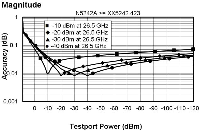
37 Dynamic Accuracy Table 30. Dynamic Accuracy - Specification Standard receiver accuracy of the test port input power reading relative to the reference input power level. It is verified with the following measurements: Compression over frequency IF linearity at a single frequency of GHz using a reference level of -20 dbm for an input power range of 0 to -60 dbm. For value below -60 dbm, refer to VNA Receiver Dynamic Accuracy Specifications and Uncertainties. Applies N5244A and N5245A with following serial numbers. N5241A: MY5241/SG5241/US5241 and above N5242A: MY5242/SG5242/US5242 and above N5241AS: MY5246/SG5246/US5246 and above N5242AS: MY5247/SG5247/US5247 and above Please download our free Uncertainty Calculator from to generate the curves for your PNA. Dynamic Accuracy, GHz Dynamic Accuracy, GHz 37


38 Dynamic Accuracy, 1 GHz Dynamic Accuracy, 10 GHz Dynamic Accuracy, 13.5 GHz 38


39 Dynamic Accuracy, 20 GHz Dynamic Accuracy, 26.5 GHz 39
40 Accuracy (nsec) Table 31. Test Port Input (Group Delay) 1 Description Typical Performance Aperture (selectable) (frequency span)/(number of points -1) Maximum Aperture Range Maximum Delay Accuracy 20% of frequency span 0.5 x (1/minimum aperture) Limited to measuring no more than 180 of phase change within the minimum aperture.) See graph below. Char. The following graph shows characteristic group delay accuracy with full 2-port calibration and a 10 Hz IF bandwidth. Insertion loss is assumed to be < 2 db and electrical length to be ten meters. For any Sij Group Delay measurement, Sii = 0, Sij = 1, Sji = 0, Skl = 0 for all kl Group Delay (Typical) 100 N5241A and N5242A All Options; Full Two Port Cal Using 85052B ij Aperture (MHz) In general, the following formula can be used to determine the accuracy, in seconds, of specific group delay measurement: ±Phase Accuracy (deg)/[360 Aperture (Hz)] Depending on the aperture and device length, the phase accuracy used is either incremental phase accuracy or worstcase phase accuracy. 1 Group delay is computed by measuring the phase change within a specified frequency step (determined by the frequency span and the number of points per sweep). 40
41 General Information Miscellaneous Information Front Panel Rear Panel Environment and Dimensions Table 32. Miscellaneous Information Description System IF Bandwidth Range CPU LXI Supplemental Information 1 Hz to 15 MHz, nominal (7 MHz, 10 MHz, and 15 MHz IFBWs are available ONLY with FW A and later, and with DSP version 5) Intel 2.0 GHz Core i7. Note: Some instruments may have a different CPU. For the latest information on CPUs and associated hard drives, visit: Class C (only applies to N5241A and N5242A models that are shipped with firmware revision A and higher) Table 33. Front Panel Information, All Options Description Typical Performance RF Connectors Test Ports Jumpers 3.5 mm (male), 50 ohm (nominal), in. Center Pin Recession (characteristic) 3.5 mm (female) connectors with SMA (male) jumper cables USB 2.0 Ports Master (4 ports) Standard Compatible with USB 2.0 Connector USB Type-A female Display Size Refresh Rate Pixels 26.3 cm (10.4 in) diagonal color active matrix LCD; 1024 (horizontal) X 768 (vertical) resolution Vertical 60 Hz; Horizontal khz A display is considered faulty if: A complete row or column consists of stuck or dark pixels. More than six stuck on pixels (but not more than three green) or more than 0.002% of the total pixels are within the LCD specifications. More than twelve dark pixels (but no more than seven of the same color) or more than 0.004% of the total pixels are within the LCD specifications. Two or more consecutive "stuck on" pixels or three or more consecutive "dark" pixel (but no more than one set of two consecutive dark pixels) Stuck on dark pixels are less than 6.5 mm apart (excluding consecutive pixels) 41
42 Table 33. (Continued) Front Panel Information, All Options Description Typical Performance Display Range Magnitude Phase Polar +/-2500 db (at 500 db/div), max +/-2500 (at 500 db/div), max 10 punits, min 10,000 Units, max Display Resolution Magnitude Phase db/div, min 0.01 /div, min Marker Resolution Magnitude Phase Polar db, min 0.01, min 10 punit, min Table 34. Rear Panel Information, All Options Description Typical Performance 10 MHz Reference In Connector Input Frequency Input Level BNC, female 10 MHz ± 10 ppm -15 dbm to +20 dbm Input Impedance 200, nom. 10 MHz Reference Out Connector Output Frequency Signal Type BNC, female 10 MHz ± 1 ppm Sine Wave Output Level +10 dbm ± 4 db into 50 Output Impedance 50, nominal Harmonics <-40 dbc, typical 42
43 Table 34. (Continued) Rear Panel Information, All Options Description Typical Performance External IF Inputs Function Connectors Allows use of external IF signals from remote mixers, bypassing the PNA's first converters SMA (female); A, B, C, D, R (4-port); A, B, R1, R2 (2-port) Frequency Path DSP Version IF Bandwidth RF Frequency IF Frequency Normal IF path: 4 All < 53 MHz MHz All >= 53 MHz MHz 5 <= 600 khz < 53 MHz MHz >= 53 MHz MHz 1 MHz All MHz 1.5 MHz All MHz 2 MHz All MHz 3 MHz All MHz 5 MHz All MHz 7 MHz All MHz 10 MHz All MHz 15 MHz All MHz Narrowband IF path: 4 or 5 All All MHz Input Impedance 50 RF Damage Level DC Damage Level 0.1 db Compression Point Normal IF path Narrowband IF path +23 dbm 5.5 VDC -9.0 dbm at MHz -17 dbm at MHz Pulse Inputs (IF Gates) Function Connectors Input Impedance Source Modulators Receiver Gates DC Damage Level Drive Voltage Internal receiver gates used for point-in-pulse and pulse-profile measurements 15-pin mini D-sub 1 K Ohm 20 ns minimum pulse width 20 ns minimum pulse width 5.5 VDC 0 V (off), +3.3 V (on), nominal 43
44 Table 34. (Continued) Rear Panel Information, All Options Description Typical Performance RF Pulse Modulator Input (Source Modulator) On/Off Ratio 10 MHz to 3.2 GHz -64 db 3.2 GHz to 13.5 GHz -80 db 13.5 GHz to 26.5 GHz -80 db Pulse Period Minimum Maximum 20 ns 70 s Pulse Outputs Voltage (TTL) Impedance High: 3.3 V to 3.5 V Low: <1 V 50 Ohm External Test Set Driver Function Connections RF, LO Output Frequency Range 1 Used for driving remote mixers SMA (female) 1.7 to 13.5 GHz (N5241A) 1.7 to 26.5 GHz (N5242A) Rear Panel LO Power Upper Limit (dbm) Lower Limit (dbm) 1.7 GHz to 13.5 GHz GHz to 18 GHz GHz to 22.5 GHz GHz to 26.5 GHz 6-5 Rear Panel RF Power Upper Limit (dbm) Lower Limit (dbm) 3.2 GHz to 13.5 GHz GHz to 20 GHz GHz to 26.5 GHz Full LO frequency range is: MHz to 13.5 GHz. (N5241A), MHz to 26.5 GHz. (N5242A) 44
45 Table 34. (Continued) Rear Panel Information, All Options Description Typical Performance VGA Video Output Connector Devices Supported: 15-pin mini D-Sub; Drives VGA compatible monitors Resolutions: Flat Panel (TFT) 1024 X 768, 800 X 600, 640 X 480 Flat Panel (DSTN) 800 X 600, 640 X 480 CRT Monitor 1280 X 1024, 1024 X 768, 800 X 600, 640 X 480 Simultaneous operation of the internal and external displays is allowed, but with 640 X 480 resolution only. If you change resolution, you can only view the external display (internal display will "white out"). Bias Tee Inputs Connectors BNC(f) for ports 1, 2, 3 and 4 Fuse Maximum Bias Current Maximum Bias Voltage Trigger Inputs/Outputs Test Set IO Power IO Handler IO GPIB Parallel Port (LPT1) USB Port LAN 500 ma, bi-pin style +/-200 ma with no degradation of RF specifications +/-40 VDC BNC(f), TTL/CMOS compatible 25-pin D-Sub connector, available for external test set control. 9-pin D-Sub, female; analog and digital IO 36-pin parallel I/O port; all input/output signals are default set to negative logic; can be reset to positive logic via GPIB command. Two ports - dedicated controller and dedicated talker/listener. 24-pin D-sub (Type D- 24), female; compatible with IEEE pin D-Sub miniature connector, female; provides connection to printers or any other parallel port peripherals Four ports on front panel (all Host) and five ports (four Host and one Device) on rear panel. Type A configuration (eight Host) and Type B configuration (one Device), USB 2.0 compatible. 10/100BaseT Ethernet, 8-pin configuration; auto selects between the two data rates Line Power Frequency, Voltage 50/60/400 Hz for 100 to 120 VAC 50/60 Hz for 220 to 240 VAC Power supply is auto switching Max 450 watts 45
46 Table 35. Analyzer Dimensions and Weight All N5241A and N5242A models are shipped with bottom feet, handles, and front and rear hardware. See detailed PNA dimension drawings at: Cabinet Dimensions Metric (mm) Imperial (inches) Height Without bottom feet: EIA RU 1 = With bottom feet Width Without handles or rack-mount flanges With handles, without rack-mount flanges With handles and rack-mount flanges Depth Without front and rear panel hardware With front and rear panel hardware, handles Weight (nominal) Net Shipping 2-port models 27 kg (60 lb) 43 kg (95 lb) 4-port models 37 kg (82 lb) 53 kg (117 lb) 1 Electronics Industry Association rack units. 1 RU = 1.75 in. Regulatory and Environmental information For Regulatory and Environmental information, refer to the PNA Series Installation and Quick Start Guide, located online at 46
47 Measurement Throughput Summary Typical Cycle Time for Measurement Completion Cycle Time vs. IF Bandwidth Cycle Time vs. Number of Points Data Transfer Time Cycle time Includes sweep time, retrace time and band-crossing time. Analyzer display turned off with DISPLAY:ENABLE OFF. Add 21 ms for display on. Data for one trace (S11) measurement. Table 36a. Cycle Time (ms) for Measurement Completion, All Options - Typical Sweep Range 9 GHz to 10 GHz 10 GHz to 13.5 GHz 13.5 GHz to 20 GHz IF Bandwidth 600 khz 10 khz 1 khz 600 khz 10 khz 1 khz 600 khz 10 khz 1 khz Number of Points Uncorrected Port cal Uncorrected Port cal Uncorrected Port cal Uncorrected Port cal Uncorrected Port cal Uncorrected Port cal Uncorrected Port cal Uncorrected Port cal Uncorrected Port cal
48 Table 36b. Cycle Time (ms) for Full-Span Measurement Completion - Typical 10 MHz to 26.5 GHz Number of Points IF Bandwidth khz 10 khz 1 khz Uncorrected Port cal Uncorrected Port cal Uncorrected Port cal Table 37. Cycle Time vs. IF Bandwidth - Typical Applies to the Preset condition (201 points, correction off) except for the following changes: CF = 10 GHz Span = 100 MHz Display off (add 21 ms for display on) Cycle time includes sweep and retrace time. Description Typical Performance IF Bandwidth (Hz) Cycle Time (ms) Trace Noise 600, , , , , , < < <
49 Table 38. Cycle Time vs. Number of Points Applies to the Preset condition (correction off) except for the following changes: CF = 10 GHz Span = 100 MHz Display off (add 21 ms for display on) Cycle time includes sweep and retrace time. Description IF Bandwidth (Hz) Number of Points 1,000 10,000 30, , ,601 1, ,401 6, ,001 16,
50 Table 39. Data Transfer Time 1 (ms) - Typical Description Number of Points ,001 SCPI over GPIB (Program executed on external PC 2 ) 32-bit floating point bit floating point ASCII SCPI over SICL/LAN or TCP/IP Socket (Program executed in the analyzer) 32-bit floating point bit floating point ASCII COM 3 (Program executed in the analyzer) 32-bit floating point < Variant type DCOM over LAN 3 (Program executed on external PC) 32-bit floating point < Variant type Measured with the analyzer display off. Values will increase slightly if the analyzer display is on. 2 Measured when using the SCPI command DISPlay: VISible OFF. 3 Values are for real and imaginary pairs, with the analyzer display off. Note: Specifications for Recall & Sweep Speed are not provided for the N5241A and N5242A analyzers. 50

51 Specifications: Front-Panel Jumpers Note: All PNA-X options have the following front-panel jumpers for each port. Measurement Receiver Inputs Reference Receiver Inputs and Reference Source Outputs Source Outputs Coupler Inputs Damage Level Table 40. Measurement Receiver Inputs (dbm) - Typical (RCVR A, B, C, D 0.1 db Typical Compression Description All Options 10 MHz to 50 MHz MHz to 500 MHz MHz to 13.5 GHz GHz to 16 GHz GHZ to 20 GHz GHZ to 26.5 GHz -4 Table 41a. Reference Receiver Inputs and Reference Source Outputs (dbm) - Typical (RCVR R1 IN, REF 1 SOURCE Max Specified Output Power Description Options 200, 400 Options 219, 419 Options 224, 423 Filtered Mode 1 Hi Power Mode 1 Filtered Mode 1 Hi Power Mode 1 Filtered Mode 1 Hi Power Mode 1 10 MHz to 50 MHz MHz to 500 MHz MHz to 3.2 GHz GHz to 10 GHz GHz to 13.5 GHz GHZ to 16 GHz GHZ to 20 GHz GHZ to 24 GHz GHZ to 26.5 GHz In Filtered Mode, the signal path goes through filters to minimize harmonics below 3.2 GHz. In Hi Power Mode, the signal bypasses the filters to maximize output power. 51
52 Table 41b. Reference Receiver Inputs and Reference Source Outputs (dbm) - Typical (RCVR R2, R3, R4 IN, REF 2, 3, 4 SOURCE Max Specified Output Power Description Option 400 Options 200, 400 Option 419 Options 219, 419 RCVR R3 IN, REF 3 SOURCE OUT RCVR R3 IN, REF 3 SOURCE OUT RCVR R2, R4 IN, REF 2, 4 SOURCE OUT RCVR R3 IN, REF 3 SOURCE OUT RCVR R3 IN, REF 3 SOURCE OUT RCVR R2, R4 IN, REF 2, 4 SOURCE OUT Filtered Mode 1 Hi Power Mode 1 Filtered Mode 1 Hi Power Mode 1 10 MHz to 50 MHz MHz to 500 MHz MHz to 3.2 GHz GHz to 10 GHz GHz to 13.5 GHz GHZ to 16 GHz GHZ to 20 GHz GHZ to 24 GHz GHZ to 26.5 GHz In Filtered Mode, the signal path goes through filters to minimize harmonics below 3.2 GHz. In Hi Power Mode, the signal bypasses the filters to maximize output power. Table 41c. Reference Receiver Inputs and Reference Source Outputs (dbm) - Typical (RCVR R2, R3, R4 IN, REF 2, 3, 4 SOURCE Max Specified Output Power Description Option 423 Options 224, 423 RCVR R3 IN, REF 3 SOURCE OUT RCVR R3 IN, REF 3 SOURCE OUT RCVR R2, R4 IN, REF 2, 4 SOURCE OUT Filtered Mode 1 Hi Power Mode 1 10 MHz to 50 MHz MHz to 500 MHz MHz to 3.2 GHz GHz to 10 GHz GHz to 13.5 GHz GHZ to 16 GHz GHZ to 20 GHz GHZ to 24 GHz GHZ to 26.5 GHz In Filtered Mode, the signal path goes through filters to minimize harmonics below 3.2 GHz. In Hi Power Mode, the signal bypasses the filters to maximize output power. 52
53 Table 42a. Source Outputs (dbm) - Typical (PORT 1, 2, 3, 4 SOURCE Max Specified Output Power Description Options 200, 400 Options 219, 419 PORT 1, 3 SORUCE OUT PORT 2, 4 SOURCE OUT PORT 1, 3 SORUCE OUT PORT 2, 4 SOURCE OUT Filtered Mode 1 Hi Power Mode 1 Filtered Mode 1 Hi Power Mode 1 10 MHz to 50 MHz MHz to 500 MHz MHz to 3.2 GHz GHz to 10 GHz GHz to 13.5 GHz GHZ to 16 GHz GHZ to 20 GHz GHZ to 24 GHz GHZ to 26.5 GHz In Filtered Mode, the signal path goes through filters to minimize harmonics below 3.2 GHz. In Hi Power Mode, the signal bypasses the filters to maximize output power. Table 42b. Source Outputs (dbm) - Typical (PORT 1, 2, 3, 4 SOURCE Max Specified Output Power Description Options 224, 423 PORT 1, 3 SORUCE OUT PORT 2, 4 SOURCE OUT Filtered Mode 1 Hi Power Mode 1 10 MHz to 50 MHz MHz to 500 MHz MHz to 3.2 GHz GHz to 10 GHz GHz to 13.5 GHz GHZ to 16 GHz GHZ to 20 GHz GHZ to 24 GHz GHZ to 26.5 GHz In Filtered Mode, the signal path goes through filters to minimize harmonics below 3.2 GHz. In Hi Power Mode, the signal bypasses the filters to maximize output power. 53
54 Table 43. Coupler Inputs (db) - Typical (PORT 1, 2, 3, 4 CPLR THRU) Insertion Loss of Coupler Thru Description Options 200, 400 Options 219, 419, 224, MHz to 50 MHz MHz to 500 MHz MHz to 3.2 GHz GHz to 10 GHz GHz to 13.5 GHz GHZ to 16 GHz GHZ to 20 GHz GHZ to 24 GHz GHZ to 26.5 GHz Table 44. Damage Level - Typical Description RF (dbm) DC (V) RCVR A, B, C, D IN 15 0 RCVR R1 IN 15 7 RCVR R2, R3, R4 IN REF 1 SOURCE OUT 15 7 REF 2, 3, 4 SOURCE OUT 15 0 PORT 1, 2, 3, 4 SOURCE OUT 15 0 PORT 1, 2, 3, 4 CPLR THRU 30 0 PORT 1, 2, 3, 4 CPLR ARM

55 Test Set Block Diagrams NOTE: For best readability, use a color printer for printing the following graphics. Legend Figure 1. 2-Port N5241A and N5242A Base Unit Option 200 Figure 2. 2-Port N5241A and N5242A Option


56 Figure 3. 2-Port N5241A and N5242A Option 224 Figure 4. 2-Port N5241A and N5242A Option 224 with


57 Figure 5. 4-Port N5241A and N5242A Base Unit Option 400 Figure 6. 4-Port N5241A and N5242A Option


58 Figure 7. 4-Port N5241A and N5242A Option 423 Figure 8. 4-Port N5241A and N5242A Option 423 with
59 Figure 9. Receiver Block Diagram A Narrowband filter IF gate Anti-alias filter ADC Digital FIR IF filter External IF input 59
 is an open standard that extends the AdvancedTCA for general purpose and semiconductor test.")
60 Agilent Updates ates Get the latest information on the products and applications you select.. AdvancedTCA Extensions for Instrumentation and Test (AXIe) is an open standard that extends the AdvancedTCA for general purpose and semiconductor test. Agilent is a founding member of the AXIe consortium. LAN extensions for Instruments puts the power of Ethernet and the Web inside your test systems. Agilent is a founding member of the LXI consortium. PCI extensions for Instrumentation (PXI) modular instrumentation delivers a rugged, PC-based highperformance measurement and automation system. Agilent Channel Partners ers Get the best of both worlds: Agilent s measurement expertise and product breadth, combined with channel partner convenience. For more information on Agilent Technologies products, applications or services, please contact your local Agilent office. The complete list is available at: Americas Canada Brazil Mexico United States Asia Pacific Australia China Hong Kong India Japan Korea Malaysia Singapore Taiwan Other AP Countries Europe & Middle East Belgium Denmark Finland France Germany Ireland Israel Italy Netherlands Spain Sweden United Kingdom For other unlisted countries: (877) (11) (800) (421) (65) (0) (0) * *0.125 /minute 49 (0) / (0) (91) (0) Product specifications and descriptions in this document subject to change without notice. Agilent Technologies, Inc. Published in USA, May 6, 2013 Supersedes: March 26, 2013 N
Advanced Test Equipment Rentals ATEC (2832)
") Established 1981 Advanced Test Equipment Rentals www.atecorp.com 800-404-ATEC (2832) Agilent 2-Port and 4-Port PNA-X Network Analyzer N5249A - 10 MHz to 8.5 GHz N5241A - 10 MHz to 13.5 GHz N5242A - 10
Established 1981 Advanced Test Equipment Rentals www.atecorp.com 800-404-ATEC (2832) Agilent 2-Port and 4-Port PNA-X Network Analyzer N5249A - 10 MHz to 8.5 GHz N5241A - 10 MHz to 13.5 GHz N5242A - 10
Keysight 2-Port and 4-Port PNA-X Network Analyzer
 Keysight 2-Port and 4-Port PNA-X Network Analyzer N5249A - 0 MHz to 8.5 GHz N524A - 0 MHz to 3.5 GHz N5242A - 0 MHz to 26.5 GHz Data Sheet and Technical Specifications Documentation Warranty THE MATERIAL
Keysight 2-Port and 4-Port PNA-X Network Analyzer
 Keysight 2-Port and 4-Port PNA-X Network Analyzer N5249A - 0 MHz to 8.5 GHz N524A - 0 MHz to 3.5 GHz N5242A - 0 MHz to 26.5 GHz Data Sheet and Technical Specifications Documentation Warranty THE MATERIAL
Keysight 2-Port and 4-Port PNA Network Analyzer N5221B 10 MHz to 13.5 GHz N5222B 10 MHz to 26.5 GHz
 Keysight 2-Port and 4-Port PNA Network Analyzer N5221B 10 MHz to 13.5 GHz N5222B 10 MHz to 26.5 GHz Data Sheet and Technical Specifications Documentation Warranty THE MATERIAL CONTAINED IN THIS DOCUMENT
Keysight 2-Port and 4-Port PNA Network Analyzer
 Keysight 2-Port and 4-Port PNA Network Analyzer N5227A 10 MHz to 67 GHz Data Sheet and Technical Specifications for Option 210 and 410 Documentation Warranty THE MATERIAL CONTAINED IN THIS DOCUMENT IS
Keysight 2-Port and 4-Port PNA Network Analyzer
 Keysight 2-Port and 4-Port PNA Network Analyzer N5221A 10 MHz to 13.5 GHz N5222A 10 MHz to 26.5 GHz Data Sheet and Technical Specifications Documentation Warranty THE MATERIAL CONTAINED IN THIS DOCUMENT
Keysight 2-Port and 4-Port PNA Network Analyzer
 Keysight 2-Port and 4-Port PNA Network Analyzer N5224A 10 MHz to 43.5 GHz N5225A 10 MHz to 50 GHz Data Sheet and Technical Specifications Documentation Warranty THE MATERIAL CONTAINED IN THIS DOCUMENT
Keysight 2-Port and 4-Port PNA Network Analyzer
 Keysight 2-Port and 4-Port PNA Network Analyzer N5227A 10 MHz to 67 GHz Data Sheet and Technical Specifications Documentation Warranty THE MATERIAL CONTAINED IN THIS DOCUMENT IS PROVIDED "AS IS," AND IS
Keysight 2-Port and 4-Port PNA Network Analyzer
 Keysight 2-Port and 4-Port PNA Network Analyzer N5221A 10 MHz to 13.5 GHz N5222A 10 MHz to 26.5 GHz Data Sheet and Technical Specifications Documentation Warranty THE MATERIAL CONTAINED IN THIS DOCUMENT
Keysight 2-Port and 4-Port PNA-L Network Analyzer
 Keysight 2-Port and 4-Port PNA-L Network Analyzer N5239A 300 khz to 8.5 GHz N523A 300 khz to 3.5 GHz N5232A 300 khz to 20 GHz Data Sheet and Technical Specifications Documentation Warranty THE MATERIAL
Keysight 2-Port and 4-Port PNA Network Analyzer
 Keysight 2-Port and 4-Port PNA Network Analyzer N5224B 10 MHz to 43.5 GHz N5225B 10 MHz to 50 GHz Data Sheet and Technical Specifications Documentation Warranty THE MATERIAL CONTAINED IN THIS DOCUMENT
Keysight 2-Port and 4-Port PNA Network Analyzer
 Keysight 2-Port and 4-Port PNA Network Analyzer N5221A 10 MHz to 13.5 GHz N5222A 10 MHz to 26.5 GHz Data Sheet and Technical Specifications for Option 210 and 410 Documentation Warranty THE MATERIAL CONTAINED
Keysight 2-Port and 4-Port Broadband Network Analyzer
 Keysight 2-Port and 4-Port Broadband Network Analyzer N5291A 500 Hz to 125 GHz Technical Specifications Documentation Warranty THE MATERIAL CONTAINED IN THIS DOCUMENT IS PROVIDED "AS IS," AND IS SUBJECT
Agilent 2-Port and 4-Port PNA Network Analyzer N5227A 10 MHz to 67 GHz
 Agilent 2-Port and 4-Port PNA Network Analyzer N5227A 10 MHz to 67 GHz Data Sheet and Technical Specifications Documentation Warranty THE MATERIAL CONTAINED IN THIS DOCUMENT IS PROVIDED "AS IS," AND IS
Agilent 2-Port and 4-Port PNA Network Analyzer
 Agilent 2-Port and 4-Port PNA Network Analyzer N5221A 10 MHz to 13.5 GHz N5222A 10 MHz to 26.5 GHz Data Sheet and Technical Specifications Documentation Warranty THE MATERIAL CONTAINED IN THIS DOCUMENT
Agilent 2-Port and 4-Port PNA Network Analyzer
 Agilent 2-Port and 4-Port PNA Network Analyzer N5224A 10 MHz to 43.5 GHz N5225A 10 MHz to 50 GHz Data Sheet and Technical Specifications Documentation Warranty THE MATERIAL CONTAINED IN THIS DOCUMENT IS
Agilent 2-Port and 4-Port PNA-L Network Analyzer N5239A 300 khz to 8.5 GHz N5231A 300 khz to 13.5 GHz N5232A 300 khz to 20 GHz
 Agilent 2-Port and 4-Port PNA-L Network Analyzer N5239A 300 khz to 8.5 GHz N5231A 300 khz to 13.5 GHz N5232A 300 khz to 20 GHz Data Sheet and Technical Specifications Documentation Warranty THE MATERIAL
Keysight 2-Port and 4-Port PNA Network Analyzer
 Keysight 2-Port and 4-Port PNA Network Analyzer N5227A 10 MHz to 67 GHz Data Sheet and Technical Specifications for Option 210 and 410 Documentation Warranty THE MATERIAL CONTAINED IN THIS DOCUMENT IS
Keysight 2-Port and 4-Port PNA Network Analyzer
 Keysight 2-Port and 4-Port PNA Network Analyzer N5227A 10 MHz to 67 Data Sheet and Technical Specifications Documentation Warranty THE MATERIAL CONTAINED IN THIS DOCUMENT IS PROVIDED "AS IS," AND IS SUBJECT
Agilent 4-Port PNA-L Network Analyzer. N5230A/C Options: 140/145/146/240/245/246 Technical Specifications
 Agilent 4-Port PNA-L Network Analyzer N5230A/C Options: 140/145/146/240/245/246 Technical Specifications Documentation Warranty THE MATERIAL CONTAINED IN THIS DOCUMENT IS PROVIDED "AS IS," AND IS SUBJECT
Agilent 2-Port and 4-Port PNA-X Network Analyzer
 Agilent 2-Port and 4-Port PNA-X Network Analyzer N5244A - MHz to 43.5 GHz N5245A - MHz to 5. GHz with Option H29 Data Sheet and Technical Specifications Documentation Warranty THE MATERIAL CONTAINED IN
Agilent 4-Port PNA-L Microwave Network Analyzer
 Agilent 4-Port PNA-L Microwave Network Analyzer N523A Options 24 and 245 3 khz to 2 GHz Data Sheet Note: Specification information in this document is also available within the PNA-L network analyzer s
Agilent. E5071C ENA Network Analyzer 9 khz to 4.5/6.5/8.5 GHz 100 khz to 4.5/6.5/8.5 GHz (with bias tees) 300 khz to 14/20 GHz (with bias tees)
 300 khz to 14/20 GHz (with bias tees)") Agilent E5071C ENA Network Analyzer 9 khz to 4.5/6.5/8.5 GHz 0 khz to 4.5/6.5/8.5 GHz (with bias tees) 300 khz to 14/20 GHz (with bias tees) E5091A Multiport Test Set E5092A Configurable Multiport Test
Agilent E5071C ENA Network Analyzer 9 khz to 4.5/6.5/8.5 GHz 0 khz to 4.5/6.5/8.5 GHz (with bias tees) 300 khz to 14/20 GHz (with bias tees) E5091A Multiport Test Set E5092A Configurable Multiport Test
Keysight Technologies E5071C ENA Vector Network Analyzer. E5092A Configurable Multiport Test Set
 Keysight Technologies E5071C ENA Vector Network Analyzer 9 khz to 4.5/6.5/8.5 GHz 100 khz to 4.5/6.5/8.5 GHz (with bias tees) 300 khz to 14/20 GHz (with bias tees) E5092A Configurable Multiport Test Set
Agilent. E5071C ENA Network Analyzer 9 khz to 4.5/6.5/8.5 GHz 100 khz to 4.5/6.5/8.5 GHz (with bias tees) 300 khz to 14/20 GHz (with bias tees)
 300 khz to 14/20 GHz (with bias tees)") Agilent E571C ENA Network Analyzer 9 khz to 4.5/6.5/8.5 GHz khz to 4.5/6.5/8.5 GHz (with bias tees) 3 khz to 14/2 GHz (with bias tees) E592A Configurable Multiport Test Set Data Sheet Table of Contents
Agilent E571C ENA Network Analyzer 9 khz to 4.5/6.5/8.5 GHz khz to 4.5/6.5/8.5 GHz (with bias tees) 3 khz to 14/2 GHz (with bias tees) E592A Configurable Multiport Test Set Data Sheet Table of Contents
Agilent. E5071C ENA Network Analyzer 9 khz to 4.5/6.5/8.5 GHz 100 khz to 4.5/6.5/8.5 GHz (with bias tees) 300 khz to 14/20 GHz (with bias tees)
 300 khz to 14/20 GHz (with bias tees)") Agilent E5071C ENA Network Analyzer 9 khz to 4.5/6.5/8.5 GHz 100 khz to 4.5/6.5/8.5 GHz (with bias tees) 300 khz to 14/20 GHz (with bias tees) E5092A Configurable Multiport Test Set Data Sheet Table of
Agilent E5071C ENA Network Analyzer 9 khz to 4.5/6.5/8.5 GHz 100 khz to 4.5/6.5/8.5 GHz (with bias tees) 300 khz to 14/20 GHz (with bias tees) E5092A Configurable Multiport Test Set Data Sheet Table of
Agilent ENA Series 2, 3 and 4 Port RF Network Analyzers E5070A 300 khz to 3 GHz E5071A 300 khz to 8.5 GHz E5091A Multiport Test Set.
 Agilent ENA Series 2, 3 and 4 Port RF Network Analyzers E5070A 300 khz to 3 GHz E5071A 300 khz to 8.5 GHz E5091A Multiport Test Set Data Sheet Definitions All specifications apply over a 5 C to 40 C range
E5071C ENA Vector Network Analyzer. E5092A Configurable Multiport Test Set
 DATA SHEET E5071C ENA Vector Network Analyzer 9 khz to 4.5/6.5/8.5 GHz 100 khz to 4.5/6.5/8.5 GHz (with bias tees) 300 khz to 14/20 GHz (with bias tees) E5092A Configurable Multiport Test Set Table of
Advanced Test Equipment Rentals ATEC (2832)
") Established 1981 Advanced Test Equipment Rentals www.atecorp.com 800-404-ATEC (2832) Technical Specifications Agilent Technologies PNA Series Network Analyzers E8801A, E8802A, and E8803A Discontinued Product
Established 1981 Advanced Test Equipment Rentals www.atecorp.com 800-404-ATEC (2832) Technical Specifications Agilent Technologies PNA Series Network Analyzers E8801A, E8802A, and E8803A Discontinued Product
Keysight Technologies E5071C ENA Network Analyzer
 Keysight Technologies E5071C ENA Network Analyzer 9 khz to 4.5/6.5/8.5 GHz 100 khz to 4.5/6.5/8.5 GHz (with bias tees) 300 khz to 14/20 GHz (with bias tees) E5092A Conigurable Multiport Test Set Data Sheet
Keysight Spectrum Analyzer Option (090/S93090xA) for PNA/PNA-L/PNA-X/N5290A/N5291A
 for PNA/PNA-L/PNA-X/N5290A/N5291A") Keysight Spectrum Analyzer Option (090/S93090xA) for PNA/PNA-L/PNA-X/N5290A/N529A Data Sheet and Technical Specifications Documentation Warranty THE MATERIAL CONTAINED IN THIS DOCUMENT IS PROVIDED "AS
Keysight Spectrum Analyzer Option (090/S93090xA) for PNA/PNA-L/PNA-X/N5290A/N529A Data Sheet and Technical Specifications Documentation Warranty THE MATERIAL CONTAINED IN THIS DOCUMENT IS PROVIDED "AS
Keysight Streamline Series
 DATA SHEET Keysight Streamline Series USB Vector Network Analyzer P937XA 2-port, up to 26.5 GHz Compact form. Zero compromise. Keysight Streamline Series: Exceptional Performance in a Small Package Balance
Agilent ENA Series 2, 3 and 4 Port RF Network Analyzers E5070A 300 khz to 3 GHz E5071A 300 khz to 8.5 GHz E5091A Multiport Test Set.
 Agilent ENA Series 2, 3 and 4 Port RF Network Analyzers E5070A 300 khz to 3 GHz E5071A 300 khz to 8.5 GHz E5091A Multiport Test Set Data Sheet Definitions All specifications apply over a 5 C to 40 C range
Agilent RF Network Analyzers PNA Series
 Agilent RF Network Analyzers PNA Series Technical Specifications This document describes the performance and features of Agilent Technologies PNA Series RF network analyzers: Agilent E8356A S-parameter
Agilent N9923A FieldFox RF Vector Network Analyzer 2 MHz to 4/6 GHz. Data Sheet
 Agilent N9923A FieldFox RF Vector Network Analyzer 2 MHz to 4/6 GHz Data Sheet Table of Contents Definitions... 2 FieldFox RF Vector Network Analyzer... 3 Cable and Antenna Analyzer (Option 305)... External
Advanced Test Equipment Rentals ATEC (2832)
") Established 1981 Advanced Test Equipment Rentals www.atecorp.com 800-404-ATEC (2832) Agilent ENA-L RF Network Analyzers E5061A, 300 khz to 1.5 GHz E5062A, 300 khz to 3 GHz Data Sheet Definitions All specifications
Established 1981 Advanced Test Equipment Rentals www.atecorp.com 800-404-ATEC (2832) Agilent ENA-L RF Network Analyzers E5061A, 300 khz to 1.5 GHz E5062A, 300 khz to 3 GHz Data Sheet Definitions All specifications
M980xA Series PXIe Vector Network Analyzer
 DATA SHEET M980xA Series PXIe Vector Network Analyzer 2/4/6-port, 9 khz to 20 GHz Drive Down the Size of Test M9800A 9 khz to 4.5 GHz M9801A 9 khz to 6.5 GHz M9802A 9 khz to 9 GHz M9803A 9 khz to 14 GHz
Agilent ENA 2 and 4 Port RF Network Analyzers
 Agilent ENA 2 and 4 Port RF Network Analyzers Data Sheet E5071C-240/440 9 khz to 4.5 GHz E5071C-245/445 0 khz to 4.5 GHz (with bias-tees) E5071C-280/480 9 khz to 8.5 GHz E5071C-285/485 0 khz to 8.5 GHz
Keysight E5063A ENA Series Network Analyzer
 Keysight E5063A ENA Series Network Analyzer 100 khz to 4.5/8.5/18 GHzz Data Sheet Deinitions Specification (spec.): Warranted performance. All speciications apply at 23 ºC (± 5 ºC), unless otherwise stated,
Keysight Streamline Series USB Vector Network Analyzer P500xA 2-port, 9 khz to 20 GHz
 Keysight Streamline Series USB Vector Network Analyzer P500xA 2-port, 9 khz to 20 GHz Compact Form. Zero Compromise. P5000A 9 khz to 4.5 GHz P5001A 9 khz to 6.5 GHz P5002A 9 khz to 9 GHz P5003A 9 khz to
Agilent ESA-L Series Spectrum Analyzers
 Agilent ESA-L Series Spectrum Analyzers Data Sheet Available frequency ranges E4403B E4408B 9 khz to 1.5 GHz 9 khz to 3.0 GHz 9 khz to 26.5 GHz As the lowest cost ESA option, these basic analyzers are
Keysight E5063A ENA Series Network Analyzer
 Keysight E5063A ENA Series Network Analyzer 100 khz to 500 M/1.5 G/3 G/4.5 G/6.5 G/8.5 G/14 G/18 GHz Data Sheet 02 Keysight E5063A ENA Series Network Analyzer - Data Sheet Deinitions Speciication (spec.):
Agilent E5072A ENA Series Network Analyzer
 Agilent E572A ENA Series Network Analyzer 3 khz to 4.5 /8.5 GHz Data Sheet Options This document provides technical specifications for the E572A ENA network analyzer. E572A-245 E572A-285 2-port with configurable
Agilent N9320B RF Spectrum Analyzer
 Agilent N9320B RF Spectrum Analyzer 9 khz to 3.0 GHz Data Sheet Definitions and Conditions The spectrum analyzer will meet its specifications when: It is within its calibration cycle It has been turned
Agilent X-Series Signal Analyzer This manual provides documentation for the following X-Series Analyzer: CXA Signal Analyzer N9000A
 Agilent X-Series Signal Analyzer This manual provides documentation for the following X-Series Analyzer: CXA Signal Analyzer N9000A N9000A CXA Functional Tests Notices Agilent Technologies, Inc. 2006-2008
R&S ZVT Vector Network Analyzer Specifications
 R&S ZVT Vector Network Analyzer Specifications Test & Measurement Data Sheet 08.00 CONTENTS Definitions... 3 Specifications... 4 Measurement range...4 Measurement speed...5 Measurement accuracy...6 Effective
R&S ZNC Vector Network Analyzer Specifications
 ZNC3_dat-sw_en_5214-5610-22_v0300_cover.indd 1 Data Sheet 03.00 Test & Measurement R&S ZNC Vector Network Analyzer Specifications 04.09.2012 13:39:47 CONTENTS Definitions... 3 Measurement range... 4 Measurement
Keysight Technologies N9320B RF Spectrum Analyzer
 Keysight Technologies N9320B RF Spectrum Analyzer 9 khz to 3.0 GHz Data Sheet Definitions and Conditions The spectrum analyzer will meet its specifications when: It is within its calibration cycle It has
Keysight Technologies E5072A ENA Series Network Analyzer 30 khz to 4.5/8.5 GHz. Data Sheet
 Keysight Technologies E572A ENA Series Network Analyzer 3 khz to 4.5/8.5 GHz Data Sheet 2 Keysight E572A ENA Series Network Analyze 3 khz to 4.5/8.5 GHz - Data Sheet Options This document provides technical
Keysight Technologies E5080A ENA Vector Network Analyzer. E5092A Configurable Multiport Test Set
 Keysight Technologies E5080A ENA Vector Network Analyzer - 9 khz to 4.5/6.5/9 GHz E5092A Configurable Multiport Test Set Data Sheet 02 Keysight E5080A ENA Vector Network Analyzer, E5092A Configurable Multiport
Keysight Technologies E5072A ENA Series Network Analyzer 30 khz to 4.5 /8.5 GHz. Data Sheet
 Keysight Technologies E572A ENA Series Network Analyzer 3 khz to 4.5 /8.5 GHz Data Sheet Options This document provides technical speciications for the E572A ENA network analyzer. E572A-245 E572A-285 2-port
Model 745 Series. Berkeley Nucleonics Test, Measurement and Nuclear Instrumentation since Model 845-HP Datasheet BNC
 Model 845-HP Datasheet Model 745 Series Portable 20+ GHz Microwave Signal Generator High Power +23dBM Power Output 250 fs Digital Delay Generator BNC Berkeley Nucleonics Test, Measurement and Nuclear Instrumentation
Vector Network Analyzers T - Series
 Datasheet Vector Network Analyzers T - Series Wide dynamic range 130 db typ. Low noise level < -120 dbm Low trace noise 1 mdb rms High measurement speed 125ms/point High effective directivity > 45 db Remote
Agilent 8360B Series Synthesized Swept Signal Generators 8360L Series Synthesized Swept CW Generators Data Sheet
 Agilent 8360B Series Synthesized Swept Signal Generators 8360L Series Synthesized Swept CW Generators Data Sheet 10 MHz to 110 GHz Specifications apply after full user calibration, and in coupled attenuator
Configuration of PNA-X, NVNA and X parameters
 Configuration of PNA-X, NVNA and X parameters VNA 1. S-Parameter Measurements 2. Harmonic Measurements NVNA 3. X-Parameter Measurements Introducing the PNA-X 50 GHz 43.5 GHz 26.5 GHz 13.5 GHz PNA-X Agilent
APPH6040B / APPH20G-B Specification V2.0
 APPH6040B / APPH20G-B Specification V2.0 (July 2014, Serial XXX-XX33XXXXX-XXXX or higher) A fully integrated high-performance cross-correlation signal source analyzer for to 7 or 26 GHz 1 Introduction
S3602C Vector Network Analyzer Datasheet
 S3602C Vector Network Analyzer Datasheet Saluki Technology Inc. The document applies to the vector network analyzers of the following models: S3602C vector network analyzer (10MHz - 43.5GHz). Options of
MG3740A Analog Signal Generator. 100 khz to 2.7 GHz 100 khz to 4.0 GHz 100 khz to 6.0 GHz
 Data Sheet MG3740A Analog Signal Generator 100 khz to 2.7 GHz 100 khz to 4.0 GHz 100 khz to 6.0 GHz Contents Definitions, Conditions of Specifications... 3 Frequency... 4 Output Level... 5 ATT Hold...
Model 7000 Series Phase Noise Test System
 Established 1981 Advanced Test Equipment Rentals www.atecorp.com 800-404-ATEC (2832) Model 7000 Series Phase Noise Test System Fully Integrated System Cross-Correlation Signal Analysis to 26.5 GHz Additive
Keysight E5063A ENA Vector Network Analyzer
 Keysight E5063A ENA Vector Network Analyzer 100 khz to 500 M/1.5 G/3 G/4.5 G/6.5 G/8.5 G/14 G/18 GHz Data Sheet 2 Keysight E5063A ENA Vector Network Analyzer - Data Sheet Table of Contents Definitions
Agilent ENA-L RF Network Analyzers
 Agilent ENA-L RF Network Analyzers E5061A, 300 khz to 1.5 GHz E5062A, 300 khz to 3 GHz Data Sheet Definitions All specifications apply over a 23 C ±5 C range (unless otherwise stated) and 90 minutes after
Specification RIGOL. 6 Specification
 Specification RIGOL 6 Specification This chapter lists the specifications and general specifications of the analyzer. All the specifications are guaranteed when the following conditions are met unless
Model 745 Series. Berkeley Nucleonics Test, Measurement and Nuclear Instrumentation since Model 845-M Specification 1.8 BNC
 Specification 1.8 Model 745 Series 0.01-20.0 GHz Low Phase Noise Synthesizer 250 fs Digital Delay Generator Berkeley Nucleonics Test, Measurement and Nuclear Instrumentation since 1963 Introduction The
Platform Migration 8510 to PNA. Graham Payne Application Engineer Agilent Technologies
 Platform Migration 8510 to PNA Graham Payne Application Engineer Agilent Technologies We set the standard... 8410 8510 When we introduced the 8510, we changed the way S-parameter measurements were made!
Keysight Technologies Making Accurate Intermodulation Distortion Measurements with the PNA-X Network Analyzer, 10 MHz to 26.5 GHz
 Keysight Technologies Making Accurate Intermodulation Distortion Measurements with the PNA-X Network Analyzer, 10 MHz to 26.5 GHz Application Note Overview This application note describes accuracy considerations
Chapter 5 Specifications
 RIGOL Specifications are valid under the following conditions: the instrument is within the calibration period, is stored for at least two hours at 0 to 50 temperature and is warmed up for 40 minutes.
SIGNAL GENERATORS. MG3633A 10 khz to 2700 MHz SYNTHESIZED SIGNAL GENERATOR GPIB
 SYNTHESIZED SIGNAL GENERATOR MG3633A GPIB For Evaluating of Quasi-Microwaves and Measuring High-Performance Receivers The MG3633A has excellent resolution, switching speed, signal purity, and a high output
AV3672 Series Vector Network Analyzer
 AV3672 Series Vector Network Analyzer AV3672A/B/C/D/E (10MHz 13.5 GHz/26.5 GHz/43.5 GHz/50 GHz/67 GHz) Product Overview: AV3672 series vector network analyzer include AV3672A (10MHz 13.5GHz), AV3672B (10MHz
S3602A/B Vector Network Analyzer Datasheet
 S3602A/B Vector Network Analyzer Datasheet Saluki Technology Inc. The document applies to the vector network analyzers of the following models: S3602A vector network analyzer (10MHz-13.5GHz). S3602B vector
DSA700 Series Spectrum Analyzer
 DSA700 Series Spectrum Analyzer Product Features: All-Digital IF Technology Frequency Range from 100 khz up to 1 GHz Min. -155 dbm Displayed Average Noise Level (Typ.) Min.
Model 865 RF / Ultra Low Noise Microwave Signal Generator
 Model 865 RF / Ultra Low Noise Microwave Signal Generator Features Excellent signal purity: ultra-low phase noise and low spurious Combination of highest output power and fastest switching Powerful touch-display
Agilent 8560 EC Series Spectrum Analyzers Data Sheet
 Agilent 8560 EC Series Spectrum Analyzers Data Sheet Agilent 8560EC 30 Hz to 2.9 GHz Agilent 8561EC 30 Hz to 6.5 GHz 1 Agilent 8562EC 30 Hz to 13.2 GHz Agilent 8563EC 30 Hz to 26.5 GHz Agilent 8564EC 30
Model 855 RF / Microwave Signal Generator
 Features Very low phase noise Fast switching Phase coherent switching option 2 to 8 phase coherent outputs USB, LAN, GPIB interfaces Applications Radar simulation Quantum computing High volume automated
Impedance 50 (75 connectors via adapters)
") VECTOR NETWORK ANALYZER PLANAR 304/1 DATA SHEET Frequency range: 300 khz to 3.2 GHz Measured parameters: S11, S21, S12, S22 Dynamic range of transmission measurement magnitude: 135 db Measurement time
VECTOR NETWORK ANALYZER PLANAR 304/1 DATA SHEET Frequency range: 300 khz to 3.2 GHz Measured parameters: S11, S21, S12, S22 Dynamic range of transmission measurement magnitude: 135 db Measurement time
Agilent ENA 2, 3 and 4 Port RF Network Analyzers E5070B 300 khz to 3 GHz E5071B 300 khz to 8.5 GHz E5091A Multiport Test Set.
 Agilent ENA 2, 3 and 4 Port RF Network Analyzers E5070B 300 khz to 3 GHz E5071B 300 khz to 8.5 GHz E5091A Multiport Test Set Data Sheet Definitions All specifications apply over a 5 C to 40 C range (unless
Vector Network Analyzers ZVB
 Specifications Version 05.00 Vector Network Analyzers ZVB September 2005 Specifications MEASUREMENT RANGE...3 MEASUREMENT SPEED...5 MEASUREMENT ACCURACY...6 EFFECTIVE SYSTEM DATA...8 TEST PORT OUTPUT...8
Agilent 8703B Lightwave Component Analyzer Technical Specifications. 50 MHz to GHz modulation bandwidth
 Agilent 8703B Lightwave Component Analyzer Technical Specifications 50 MHz to 20.05 GHz modulation bandwidth 2 The 8703B lightwave component analyzer is a unique, general-purpose instrument for testing
Agilent E7400A Series EMC Analyzers
 Agilent E7400A Series EMC Analyzers Data Sheet These specifications apply to the Agilent Technologies E7402A and E7405A EMC analyzers. Frequency Specifications Frequency range E7402A dc coupled 100 Hz
Agilent Technologies PSA Series Spectrum Analyzers Test and Adjustment Software
 Test System Overview Agilent Technologies PSA Series Spectrum Analyzers Test and Adjustment Software Test System Overview The Agilent Technologies test system is designed to verify the performance of the
R&S ZNB Vector Network Analyzer Specifications
 Umschlag_ZNB4-8_dat-sw_en_5214-5384-22.indd 1 Data Sheet 02.00 Test & Measurement R&S ZNB Vector Network Analyzer Specifications 07.11.2011 10:03:35 CONTENTS Definitions... 3 Measurement range... 4 Measurement
Model 865-M Wideband Synthesizer
 Model 865-M Wideband Synthesizer Features Wideband Low phase noise Fast switching down to 15 µs FM, Chirps, Pulse Internal OCXO, external variable reference Single DC supply Applications ATE LO for frequency
Key Reference. Agilent Technologies E8257D/67D PSG Signal Generators. Manufacturing Part Number: E Printed in USA July 2007
 Agilent Technologies E8257D/67D PSG Signal Generators This guide applies to the following signal generator models: E8267D PSG Vector Signal Generator E8257D PSG Analog Signal Generator Due to our continuing
Model 865-M Wideband Synthesizer
 Model 865-M Wideband Synthesizer Features Wideband Low phase noise Fast switching down to 20 µs FM, Chirps, Pulse Internal OCXO, external variable reference Single DC supply Applications ATE LO for frequency
N5194A and N5192A. UXG Agile Vector Adapter 50 MHz to 20 GHz DATA SHEET
 N5194A and N5192A UXG Agile Vector Adapter 50 MHz to 20 GHz DATA SHEET Table of Contents Definitions and Conditions... 03 Specifications... 04 Frequency... 04 Amplitude... 05 Switching speed... 04 Synchronization...07
Compact Series: S5065 & S5085 Vector Network Analyzers KEY FEATURES
 Compact Series: S5065 & S5085 Vector Network Analyzers KEY FEATURES Frequency range: 9 khz - 6.5 or 8.5 GHz Measured parameters: S11, S12, S21, S22 Wide output power adjustment range: -50 dbm to +5 dbm
Agilent N9343C Handheld Spectrum Analyzer (HSA)
") Test Equipment Depot - 800.517.8431-99 Washington Street Melrose, MA 02176 - TestEquipmentDepot.com Agilent N9343C Handheld Spectrum Analyzer (HSA) 1 MHz to 13.6 GHz (tunable to 9 khz) Data Sheet Field
Test Equipment Depot - 800.517.8431-99 Washington Street Melrose, MA 02176 - TestEquipmentDepot.com Agilent N9343C Handheld Spectrum Analyzer (HSA) 1 MHz to 13.6 GHz (tunable to 9 khz) Data Sheet Field
Model 845-M Low Noise Synthesizer
 Model 845-M Low Noise Synthesizer Features Low phase noise Fast switching down to 20 µs FM, Chirps, Pulse Internal OCXO, external variable reference Single DC supply Applications ATE LO for frequency converters
PNA Family Microwave Network Analyzers (N522x/3x/4xB) CONFIGURATION GUIDE
 CONFIGURATION GUIDE") PNA Family Microwave Network Analyzers (N522x/3x/4xB) CONFIGURATION GUIDE Table of Contents PNA Family Network Analyzer Configurations... 05 Test set and power configuration options...05 Hardware options...
PNA Family Microwave Network Analyzers (N522x/3x/4xB) CONFIGURATION GUIDE Table of Contents PNA Family Network Analyzer Configurations... 05 Test set and power configuration options...05 Hardware options...
Agilent ENA 2, 3 and 4 Port RF Network Analyzers E5070B 300 khz to 3 GHz E5071B 300 khz to 8.5 GHz E5091A Multiport Test Set
 View at www.testequipmentdepot.com Agilent ENA 2, 3 and 4 Port RF Network Analyzers E5070B 300 khz to 3 GHz E5071B 300 khz to 8.5 GHz E5091A Multiport Test Set Data Sheet Test Equipment Depot - 800.517.8431-99
Agilent 8560 E-Series Spectrum Analyzers
 Agilent 8560 E-Series Spectrum Analyzers Data Sheet 8560E 30 Hz to 2.9 GHz 8561E 30 Hz to 6.5 GHz 8562E 30 Hz to 13.2 GHz 8563E 30 Hz to 26.5 GHz 8564E 30 Hz to 40 GHz 8565E 30 Hz to 50 GHz 8565E SPECTRUM
This section lists the specications for the Agilent 8360 B-Series. generators, Agilent Technologies has made changes to this product
 2c Specifications This section lists the specications for the Agilent 8360 B-Series swept signal generator. In a eort to improve these swept signal generators, Agilent Technologies has made changes to
R&S ZVT Vector Network Analyzer Specifications
 ZVT_dat-sw_en_0758-065-22_v0900_cover.indd Data Sheet 09.00 Test & Measurement R&S ZVT Vector Network Analyzer Specifications 06.03.205 5:50:4 CONTENTS Definitions... 3 Specifications... 4 Measurement
specifications Network Analyzers HP 8753ET and 8753ES Network Analyzers 30 khz to 3 or 6 GHz
 specifications 8753ET/ES Network Analyzers HP 8753ET and 8753ES Network Analyzers 30 khz to 3 or 6 GHz This document describes the performance and features of the following products: HP 8753ES S-parameter
Network Analyzers. R3765G/3767G Series. R3765G/67G Series Network Analyzers. 300 khz to 3.8 GHz/300 khz to 8 GHz
 (Photo is R3767CG) R3765G/67G Series Network Analyzers The R3765G/67G-series network analyzers are vector network analyzers that incorporate a new RF circuit analysis technique. The measuring frequency
SC5407A/SC5408A 100 khz to 6 GHz RF Upconverter. Datasheet. Rev SignalCore, Inc.
 SC5407A/SC5408A 100 khz to 6 GHz RF Upconverter Datasheet Rev 1.2 2017 SignalCore, Inc. support@signalcore.com P R O D U C T S P E C I F I C A T I O N S Definition of Terms The following terms are used
Spectrum Analyzers 2680 Series Features & benefits
 Data Sheet Features & benefits n Frequency range: 9 khz to 2.1 or 3.2 GHz n High Sensitivity -161 dbm/hz displayed average noise level (DANL) n Low phase noise of -98 dbc/hz @ 10 khz offset n Low level
DSA800. No.1 RIGOL TECHNOLOGIES, INC.
 No.1 DSA800 9 khz to 1.5 GHz Frequency Range Typical -135 dbm Displayed Average Noise Level (DANL) -80 dbc/hz @10 khz offset Phase Noise Total Amplitude Uncertainty
FREEDOM Communications System Analyzer R8600 DATA SHEET
 FREEDOM Communications System Analyzer R8600 DATA SHEET Table of Contents Operating/Display Modes 3 General 3 Generator (Receiver Test) 4 Receiver (Transmitter Test) 5 Spectrum Analyzer 6 Oscilloscope
Agilent 83711B and 83712B Synthesized CW Generators
 View at www.testequipmentdepot.com Agilent 83711B and 83712B Synthesized CW Generators Agilent 83731B and 83732B Synthesized Signal Generators Data Sheet 10 MHz to 20 GHz 1 to 20 GHz Specifications describe