Department of Electrical and Computer Systems Engineering
|
|
|
- Jonas Fields
- 6 years ago
- Views:
Transcription

1 Department of Electrical and Computer Systems Engineering Technical Report MECSE Double-Sideband Carrier Suppressed RZ and NRZ Modulation Formats for Ultra-high Capacity 40 Gb/s DWDM Optical Communications Systems... Le Nguyen Binh and Zsofia Csematony
2 DOUBLE-SIDEBAND CARRIER SUPPRESSED RZ and NRZ MODULATION FORMATS FOR ULTRA-HIGH CAPACITY 40 Gb/s OPTICAL COMMUNICATIONS SYSTEMS Le Nguyen Binh and Zsiofia Csematony Groupe de Photonics Applique et Communications Fibre Optique (GPACFO) Centre for Telecommunications and Information Engineering Department of Electrical and Computer Systems Engineering Monash University, Clayton 3168 Australia ABSTRACT Due to the enormous increase and future demands in data traffic on the Internet and other global telecommunications networks, the current focus of research and development is on the 40Gbps per channel; dense wavelength division multiplexed (DWDM) optical transport system. In order to realize a 40Gbps system, high speed electronic, optical and optoelectronic components and novel modulation, resilience in transmission impairments and transmission techniques are essential. The design and implementation of such large networks is a costly and time-consuming exercise, because the design procedures involved are complex. Hence development of a CAD package would enhance the engineering process of these optical communications networks. When the transmission bit rate is increased especially to the rate at which the fibre dispersion becomes very sensitive to the signal bandwidth and when the average power of all multiplexed channels is reaching the level of nonlinealy induced distortion, the suppression of the optical carrier is thus very essential. Double-sideband carrier-suppressed return-to-zero (DSB CS-RZ) modulation format has been included for the first time to enhance the system BER performance. Its advantages has been well- know in traditional communications systems In this report, this technique is applied in optical communication domain to provide similar benefits in spectral efficiency, as well as a novel exploration in the reduction of dispersion penalties and minimising the effects of nonlinearities under the multiplexing of several optical channel propagating through a single fibre transmission medium, the dense wavelength division multiplexed (DWDM) optical transmission system 1
3 Numerical simulations have been conducted to investigate system performance with signals modulated with different formats in dispersion managed long-haul 40Gbps DWDM communication systems. The second version of the Monash Optical Communications systems Simulator (MOCSS-2) has been further developed so that it can be used as a computer aided development (CAD) tool to model essential devices and technologies optimized for WDM, long haul, 40Gbps per channel optical communications systems. 2
4 TABLE OF CONTENTS TABLE OF CONTENTS 3 TABLE OF FIGURES 4 1 BACKGROUND 7 2 MOTIVATION 8 3 LASER SOURCE AND MODULATION TECHNIQUES INTRODUCTION THE MACH-ZEHNDER INTERFEROMETRIC INTENSITY MODULATOR Modulator Structure and Optimal Parameters MODELLING OF LIGHTWAVES GENERATION BY DFB LASER Distributed Feedback Semiconductor Laser Threshold Conditions and Optical and Electrical Characteristics of DFB Lasers Modelling of the DFB laser operation in MOCSS FURTHER DEVELOPMENT MODULATION SCHEMES USED IN LONG-HAUL HIGH-SPEED DISPERSION- MANAGED WDM COMMUNICATIONS NETWORKS INTRODUCTION NON-RETURN-TO-ZERO MODULATION FORMAT Modelling of NRZ modulation format RETURN-TO-ZERO MODULATION FORMAT Generation of RZ modulation format DOUBLE-SIDEBAND CARRIER-SUPPRESSED RETURN-TO-ZERO FORMAT FOR HIGH SPEED OPTICAL NETWORKS Introductory remarks Techniques Generation of DSB CS-RZ CS-RZ SIGNAL CHARACTERISTICS COMPARED TO CONVENTIONAL RZ MODULATED SIGNALS AT 40GBPS Effect of Modulation Depth on the Power Carried by the Significant Frequencies Practical Limitations Modified CS-RZ modulation scheme Soliton-like RZ pulses CONCLUSION FURTHER WORK PULSE PROPAGATION IN FIBRES MAXWELL S EQUATIONS WAVE PROPAGATION OF LIGHT IN NONLINEAR, DISPERSIVE FIBRE Nonlinear Optical Effects Mathematical Description of wave Propagation in Nonlinear Fiber Medium NONLINEAR REFRACTION EFFECTING WAVE PROPAGATION IN OPTICAL FIBRES SPLIT-STEP FOURIER METHOD AND NONLINEAR SCHRÖDINGER EQUATION LIMITATIONS OF THE MODEL EYE PATTERN AS AN ANALYSIS TOOL FOR SYSTEM PERFORMANCE COMPARISON OF THE PERFORMANCE OF CS-RZ VERSUS CONVENTIONAL RZ AND NRZ FORMATS IN SIMULATED WDM SIGNAL TRANSMISSION INTRODUCTION MATHEMATICAL MODEL Experimental Setup GBPS (8 40GBPS/CHANNEL) WDM TRANSMISSION WITH 0.8 NM (100GHZ AT 1550NM) SPACING IN THE C-BAND USING CONVENTIONAL NRZ, RZ AND THE PROPOSED CS-RZ MODULATION FORMATS Transmitted Signals Power Spectrum DISPERSION TOLERANCE MEASUREMENT NONLINEAR TOLERANCE MEASUREMENT CONCLUDING REMARKS CONCLUSIONS 64 REFERENCES 64 3
5 TABLE OF FIGURES Figure 1-1 A schematic diagram of a Mach-Zehnder modulator in the OFF state...10 Figure 1-2 Transimpedance characteristics of the MZ modulator...11 Figure 1-3 Distributed feedback (DFB) laser structure...14 Figure 1-4 Optical output power versus laser diode current [Agrawal, 1995]...16 Figure 1-5 DFB (1550nm center wavelength) spectral linewidth and phase characteristics...17 Figure 2-1 Conventional NRZ and RZ modulation code for the data sequence Figure 2-2 Applied voltage and the corresponding baseband power specrtal density for bit sequence Figure 2-3 Optical power and corresponding power spectral density of a 1550nm carrier modulated by 40Gbps NRZ with m=80%...22 Figure 2-4 Modulating voltage and power spectral density for generating a 16 bits sequence in RZ format at 40Gbps...24 Figure 2-5 Optical power and corresponding power spectral density of a carrier modulated by 40Gbps RZ with modulation index of 90%...25 Figure 2-6 Schematics showing CS-RZ generation...30 Figure 2-7 Optical power spectral density of a 16-bit sequence modulated by 40Gbps CS-RZ...31 Figure 2-8 a.) Optical spectrum of the carrier modulated with 40Gbps CS-RZ and b.) conventional RZ...33 Figure 2-9 Filtered optical spectrum of a.) the proposed CS-RZ format and b.) the conventional RZ signal at 40Gbps (with 30dB amplification)...33 Figure 2-10 Carrier and sideband frequency power content versus modulation depth in the CS-RZ format Figure 2-11 Ideal pulse (top) and practical pulse shape (bottom...35 Figure 2-12 Narrow, sharp pulses produced by theoretical CS-RZ modulation techniques...36 Figure 2-13 Optical duobinary signal generation...36 Figure 2-14 Principle of the first stage of CS-RZ modulation...38 Figure 2-15 CS-RZ modulated pulse train before and after signal smoothing...39 Figure 2-16 Power spectrum of the proposed CS-RZ signal modulated at 40Gbps...40 Figure 3-1 Schematic illustration of the split-step Fourier method...46 Figure 3-2 Limitations on the channel power imposed by the four non linear effects around 1550nm [Keiser, 1997]...49 Figure 3-3 Basic equipment used for eye-pattern generation...50 Figure 4-1 Power content [dbm] of the carrier frequency in RZ and the sideband frequency of CS-RZ versus duty ratio Figure 4-2 Simulated experimental setup for comparison of nonlinear and dispersion tolerance between CS-RZ and conventional RZ and NRZ...53 Figure channel WDM spectra in the C-band with 0.8nm spacing from nm nm using a.) conventional NRZ and b.) RZ modulation and c.) the proposed CS-RZ format...55 Figure 4-4 System back-to-back power spectrum for 8 channels with 1.6nm spacing...55 Figure 4-5 Multiplexed power spectral density of the modulated carriers using the CS-RZ format...56 Figure 4-6 Multiplexed power spectral density of the three RZ modulated carriers used in the simulation with 1.6nm spacing...56 Figure 4-7 Back-to-back system eye-diagram for a.) CS-RZ b.) conventional RZ modulation format and c.) NRZ modulation at 40Gbps...57 Figure 4-8 Eye-diagrams after transmission over 5km of SMF...58 Figure 4-9 Eye-diagram after 50km of transmission in DCF fiber...60 Figure km of SMF with amplification CS-RZ Signal transmission over...61 Figure 4-11 RZ Signal transmission over 5km of SMF with amplification...62 Figure 4-12 NRZ Signal transmission over 5km of SMF with amplification
6 SYMBOLS AND ABBREVIATIONS BER CNR CS CW DCF DFB DSB EDFA FP FWHM FWM GVD GVD H IC ISI LO LSB m MOCSS MZIM bit error rate carrier-to-noise ratio carrier-suppressed Continuous wave dispersion-compensating fibre distributed feedback double sideband erbium-doped fiber amplifier Fabry-Perot full width at half maximum four-wave mixing group velocity dispersion group velocity dispersion ridge height (MZ) integrated circuit intersymbol interference local oscillator lower sideband modulation index Monash Optical Communications Systems Simulation Mach-Zehnder intensity modulator 5
7 NRZ NSE OSNR OTDM OTDM RZ SMF SPM T USB WDM XPM non-return-to-zero nonlinear Schrodinger equation optical signal-to-noise ratio optical time interleaving optical time-domain multiplexing return-to-zero single mode fiber self phase modulation electrode thickness (in MZ) upper sideband Wave Division Multiplex cross phase modulation 6
8 1 Background With the explosion of the Internet in recent years, there is an ever-increasing demand from network operators for greater bandwidth, higher line rate, higher channel count, longer system reach and higher spectral efficiency. 40Gbps based WDM systems are now the focus of research and investigation because they are very attractive to meet these demands. They allow the reduction of the number of multiplexed channels, which simplifies network management and saves on the wavelength resources. There have been some impressive demonstrations of 40Gbps line-rate transmission over single and multi-channel WDM systems in the past two years. Deploying 40Gbps cannels instead of the currently used 10Gbps WDM channels are only feasible and attractive, if the same span length and transmission distances can be achieved. Increasing the line rate from 10Gbps to 40Gbps requires a 6dB increase in the received optical-signal-to-noise (OSNR). This can be achieved by shortening the amplifier spans or increasing launch power per span. However, at greater transmission power levels, nonlinear effects, such as self phase modulation (SPM) and cross-phase modulation (XPM) become significant in determining the system performance. To improve the nonlinear tolerance, it is important to select the appropriate modulation format. Various transmission formats have been investigated recently to find one with superior nonlinear tolerance. Double-Sideband Carrier-Suppressed Return-to-Zero (DSB-CS-RZ) modulation format has been shown to deliver excellent transmission performance. Conventional intensity modulation has a large carrier component, which carries most of the power in the signal, but contains no useful information. In DSB-CS modulation, the carrier component of the signal is removed. Hence the input power into the fiber is reduced. This allows the use of optical amplifiers immediately following the modulator. By amplifying the sidebands right out of the modulator, the high OSNR at the modulator can be preserved throughout the system in spite of the losses. Lower input signal powers also mean, that nonlinear effects are reduced. CS-RZ modulation format has been shown experimentally to offer high fibre nonlinearity tolerance. 7
9 2 Motivation Dispersion and nonlinear effects are two of the major obstacles to the implementation of ultra-high speed WDM optical communication systems. Dispersion is usually managed by using short dispersion compensating fibre (DCF) sections to compensate for the large dispersions in the single mode (SMF) transmitting fibre. In such dispersion managed systems overall dispersion accumulation is minimised due to the opposite dispersion slopes of SMF and DCF. However, various problems arise due to the nonlinear effects of the fibre. In this report we demonstrate that the proposed Double-Sideband Carrier-Suppressed Return-to-Zero (DSB CS-RZ) modulation format achieves a superior performance over other conventional modulation formats to combat the nonlinear effects that limit the capacity of high-speed WDM optical communication systems. This new functionality is a contribution to the development of MOCSS-2 which is a comprehensive and reliable software package that can be used as a computer aided development (CAD) tool to model essential devices and technologies optimised for WDM, long haul, 40Gbps per channel optical communications systems. It enables network designers to simulate and optimise the performance of various network connection configurations before installation. 3 Laser Source and External Optical Modulation Techniques 3.1 Introduction The modulation format chosen to transmit signals in high-speed WDM communication systems is vital in achieving good system performance. CS-RZ format is the currently emerging technology for 40Gbps optical systems because of its high dispersion tolerance and more importantly, for its high nonlinearity tolerance compared to other, conventional modulation formats, such as RZ or NRZ. CS-RZ employs external modulation to modulate the laser signal. External modulation is the preferred way as it avoids spectral broadening which can lead to serious dispersion problems, harmonic distortions and frequency chirping in optical pulses generated by direct modulated lasers. Frequency chirping refers to the phase modulation in the optical carrier wave over time. Frequency chirping is due to the 8
10 periodical variation in the refractive index of the laser, which in effect is due to the changing amplitude of the modulating current. Using a continuous wave carrier with external modulation will avoid this frequency chirping and thus reduce the extent of phase modulation in the transmission. External modulation keeps the spectrum of the source constant and narrow, which results in lower dispersion values in the fibre. Typically, a semiconductor laser (such as those used in optical communication systems) can be directly modulated up to about 5Gbps. The limiting factor here is the time response of the electrical components of the laser driving circuit, which provides the electrical modulation signal. Clearly, 5Gbps is too slow for today s systems and is inappropriate to use in further developments and for higher modulation rates. The solution is to use a laser source at constant current with continuous wave output and then modulate this carrier frequency by a high-speed external modulator. The continuous wave semiconductor laser source has been chosen to be the distributed feedback laser (DFB) mostly because of its narrow linewidth of 0.2nm and frequency stability. The laser source is also tunable to any particular selected wavelength for the carrier. In the following, the laser is tuned to 1550 nm if not otherwise stated. 3.2 The Mach-Zehnder Interferometric Intensity Modulator The modulator of interest in high performance, long-haul communication systems is the popular LiNbO 3 Mach-Zenhder (MZM) optical intensity modulator. It has a large mode field diameter and hence a good light confinement factor, small coupling loss and far better interaction speed with light than electronic components. It is also integrated with other photonic components onto a single opto-electronic substrate Modulator Structure and Optimal Parameters The MZ modulator has an interferometric optical waveguide structure in which the input lightwave intensity is split equally into two paths by an input coupler. One of the arms is modulated by a controllable travelling wave electrode that introduces an electric field across the optical guiding region and hence exerting a π phase shift into the optical wave guided-wave in that arm. Phase shift occurs due to small variations in the applied modulation voltage V m (t), which in turn causes a small change in the refractive index of the electro-optic waveguide material. The change in the refractive index profile causes a small change in the propagation constant of the wave and hence 9
11 a phase shift. At the output port the lightwaves are combined to produce either a constructive or destructive interference. The former is referred to as ON state or logic 1 and occurs, when the lightwaves in the two arms are in phase. Destructive interference occurs, when the modulation voltage produces a 180 (or π) phase difference between the two arms. The output is then referred to as OFF state or a logic 0 signal. MZ modulator achieves intensity modulation by phase modulation. A schematic diagram of a typical MZ modulator is shown on Figure 3-1. The bandwidth of the modulator modelled in MOCSS-2 is 30GHz. The bandwidth of the MZ modulator is limited by electrode conductor loss. To combat this limitation, a thick electrode is used, which causes the capacitance to go high and thus the characteristic impedance of the electrode is reduced. A high ridge was also found to lower conductor loss. Another limitation to modulator bandwidth is the velocity mismatch between the guided optical wave and the applied electric signal. This mismatch is mainly due to the high dielectric constant of the LiNbO 3 material. To reduce this mismatch, the electrodes of the MZM are coated with low dielectric constant material such as SiO 3. Thus the ridge structure of the modulator is fabricated with thick, SiO 3 coated electrodes and a high ridge to effectively reduce the required driving voltage and reduce conductor loss. Figure 3-1 A schematic diagram of a Mach-Zehnder modulator in the OFF state The modelled MZ modulator in MOCSS-2 is a fabricated waveguide in LiNbO 3 with a ridge height of H=3.3µm and electrode thickness of T = 10µm, because it gives an optimal performance with a bandwidth of 30GHz, a small conductor loss and fast interaction with the guided electromagnetic wave. The 180 or π phase shift driving voltage, V m (t) = V π, is 5V and insertion loss due to coupling losses at the input and 10
12 output connector is 6dB. V π is the driving voltage that achieves a π phase difference between the two guided waves and results (theoretically) in a complete cancellation of the carrier wave at the output port. Therefore V m,on = 0 and V m,off = V π and the power transfer or extinction ratio characteristics is modelled by the following relationship as a function of the driving voltage: P out = P in πvm ( t) cos 2 ( 3-1) 2V π The transfer characteristics of a typical MZ modulator is shown on Figure 3-2. Figure 3-2 Transimpedance characteristics of the MZ modulator For the conventional NRZ and RZ modulation formats the effective DC bias voltage V m (t) = V bias is chosen to be the middle of the driving voltage range, that is the phase quadrature voltage, to preserve linearity, that is V V π bias = ( 3-2) 2 The modulation index, m, is a design parameter used to adjust the modulation efficiency described by the relationship: modulation efficiency = 1+ 1 m m ( 3-3) The higher the modulation index m, the greater the modulation efficiency, which means, that the OFF state power is strengthened and the ON state power is lowered in the following way: 11
13 V V on off = (1 m) V = (1 + m) V bias bias ( 3-4) In modern optical communications systems, the modulation index is chosen to be only a few percent to preserve linearity. However, it means, that most of the power resides in the carrier frequency, and this has detrimental effects on the performance of the system. It is therefore desirable to remove the carrier signal component, which contains no information. Techniques to suppress the carrier during modulation will be discussed in the following chapter. 3.3 Modelling of lightwaves generation by DFB laser The laser requirements for current WDM communication systems include: continuous operation at room temperature and above; reliable operation lifetime as long as hours; narrow spectral linewidth at the specified wavelength; high modulation bandwidth; well directed output for efficient coupling into the fiber; short- and longterm temporal stability of the optical output power; be tuneable; high radiance and low threshold current. This section describes the design and examines the electrical and optical characteristics of the very important distributive feedback semiconductor laser (DFB), which satisfies the above requirements and is used extensively as continuous lightwaves sources in DWDM optical fiber communication systems. A limiting factor that determines the performance of a long-haul, high-speed system is the linewidth of the light source. Standard SMF operating at 1550nm can have a dispersion coefficient as much as 20ps/m.km. With a Fabry-Parot laser, the modulated linewidth is typically a couple of nm, producing some 30-40ps/km dispersion and limiting the bit-rate distance product to only a few Gbps.km. For ultra-high bit rates, this limits the repeater spacing to a few km, whereas attenuation limited spacing for the same configuration is more than 100km. Therefore, a much narrower source linewidth is required for improved system performance. For high-speed, long-distance communications, therefore a single-mode laser is needed, one which contains only a single longitudinal mode and a single traverse mode. 12
14 3.3.1 Distributed Feedback Semiconductor Laser To achieve a stable and narrow spectral linewidth, the DFB laser cavity has an in-built wavelength-selective mechanism that enhances the gain of one mode relative to all others. The amplification is achieved by a periodic structure, or grating, which is a passive waveguide layer adjacent to the active region. The optical wave propagates parallel to this grating. The operation of the DFB is based on the distributed Bragg phase-grating reflector, which is essentially a region of periodically varying reflective index that causes two backward propagation twaves to couple back to the resonant cavity [Keiser, 1991]. The coupling is maximum for wavelength close to the Bragg wavelength λ B, which is related to the structural and index profile of the laser as n e Λ λ B = 2 ( 3-5 ) k where n e is the effective refractive index of the mode, Λ is the period of corrugation and k is the order of the grating. First order gratings (k = 1) provide the strongest coupling. In an ideal DFB laser, the longitudinal modes are spaced symmetrically around λ B at wavelengths given by 2 λb 1 λ = λm ± m + ( 3-6) 2n L 2 e e where L e is the effective grating length and m = 0, 1, 2,.. is the mode order. The coupling between the forward and backward waves is strongest for the zero-order Bragg diffraction (m = 0). The amplitudes of successive higher-order modes are greatly reduced by cavity losses. The performance of single-longitudinal-mode laser can be characterised by the mode-suppression ratio (MSR) defined as : Power in the lasing mode MSR = ( 3-7) Power in the most dominat side mode For a good laser, the first-order mode is more than 30dB down from the zero-order amplitude and this represents an MSR of However, larger gain margin is needed when DFB lasers are modulated directly. Theoretically, the two zero-order modes on either side of the Bragg wavelength should experience the same lowest threshold gain and should lase simultaneously in 13

15 the symmetrical structure of a DFB laser. However, due to randomness of the cleaving process, there is an imbalance in the modal gain characteristics of the laser and this results in a single-mode operation. This asymmetry can be further enhanced by placing different reflection coatings on each end of the cavity. Fabrication of DFB lasers require advanced technology with multiple epitaxial growths. Holographic technique is often used to form a grating with a 0.23µm periodicity for a first-order grating operating at 1550nm wavelength. An appropriate value for n e is 3.4. The schematics in Figure 3-3 shows the DFB laser structure with the built-in wavelength-selective resonator grating. Figure 3-3 Distributed feedback (DFB) laser structure Threshold Conditions and Optical and Electrical Characteristics of DFB Lasers Laser action is the result of three key processes; photon absorption, spontaneous emission and stimulated emission. Spontaneous emission is random in nature and appears as a narrow bandwidth Gaussian noise output. Radiation quanta emitted under simulated emission have the same frequency as the simulating radiation and this radiation is said to be coherent. Simulated emission will only become significant, when the rate of simulated emission exceeds the rate of absorption. This condition is known as population inversion and it is achieved by injecting electrons into the material to pump up the energy of the electrons inside the active medium. The power of the beam increases as it passes through the lasing medium and this is characterised by the gain coefficient a 0. Optical amplification is provided by the grating along the active cavity as described in the previous section. Lasing occurs, when the gain of the guided mode exceeds the optical loss during one round trip through the cavity. 14
16 The relationship between optical output power and laser drive current is shown on Figure 3-4. At low driving currents, simulated emission does not exceed absorption and spontaneous emission dominates the output. The spectral range of this emission is broad. The minimum amount of gain necessary for the operation of the laser can be realised only when the laser is pumped above a threshold level. The current needed to reach this threshold is called the threshold current, I th. There is a sharply defined increase in the output power at I th. The threshold current is defined as I th = qv N 1 + Γa vgτ p a o τ c 0 where q - electron charge, q = C; V a active layer volume, V a = m 3 ; τ c - carrier lifetime, τ c = sec. ; τ p - photon lifetime, τ p = sec.; N 0 - carrier density at transparency, N 0 = m -3 ; Γ - optical waveguide confinement factor, Γ = 0.4.; a 0 - gain coefficient, a 0 = ; v g guided lightwaves group velocity, v g = m/s. Furthermore, some other terms defined in MOCSS-2 are the overall differential quantum efficiency, η, defined as the number of photons emitted per radiative electron-hole pair recombination above threshold and η = 4.2%. The operating wavelength of the laser is λ = 1550nm, but can be tuned to other various wavelengths. The spectral linewidth of an optical source is defined as the range of wavelength over which the spectral power exceeds 50% of the peak spectral power. This is the Full_Width-at-Half-Maximum (FWHM) spectral width, σ λ. To avoid dispersive effects in long-haul high-speed WDM communication systems, the linewidth of the source must be no more than 1nm. The DFB laser modelled in MOCSS-2 has a narrow spectral linewidth; σ λ = 0.2nm. 15
17 Figure 3-4 Optical output power versus laser diode current [Agrawal, 1995] Modelling of the DFB laser operation in MOCSS-2 The high-speed optical carrier and optical power at the laser output is numerically solved by the single mode rate equation calculation using 4 th and 5 th order Runga- Kutta algorithms. Carrier Rate Equation: ) ( ) ( ) ( 1 ) ( ) ( ) ( ) ( 0 0 t F t S t S N t N a v t N qv t T dt t dn N g n a + + = ε τ ( 3-8) Photon Rate Equation: ) ( ) ( ) ( 1 ) ( 1 ) ( ) ( 0 0 t F t N t S t S N t N v a dt t ds s n p g + Γ + + Γ = τ β τ ε ( 3-9 ) 16 MECSE : "Double-Sideband Carrier Suppressed RZ and NRZ...", Le Nguyen Binh and Zsofia Csematony
, F N (t) and F φ (t) (Langevin noise sources) represent noise sources doe to spontaneous emission, carrier generation recombination process and generated")
18 Phase Rate Equation: dφ ( t) m dt α 1 = Γa0vg ( N( t) N 0 ) + Fφ ( t) ( 3-10) 2 τ p α - optical linewidth enhancement factor, α = 5 ; ε - gain compression factor, ε = and φ m optical phase, and F S (T), F N (t) and F φ (t) (Langevin noise sources) represent noise sources doe to spontaneous emission, carrier generation recombination process and generated phase, respectively. Rise and fall time is 10ps and the average output power is 2.5mW. The laser can be modulated either by direct intensity modulation or by employing external modulators, such as a LiNbO 3 Mach-Zehnder interferometer. For modern WDM systems in particular, DFB lasers are employed with external modulation due to the narrow spectral linewidth and small modulation chirping. Figure 3-5 DFB (1550nm center wavelength) spectral linewidth and phase characteristics Noise power and pulse broadening or chirping calculations are also included in the laser model. The two fundamental noise mechanisms are spontaneous emission and electron-hole recombination (shot noise) and these result in fluctuations in the 17
19 intensity, phase and frequency of the carrier signal, even, when the laser is biased at a constant current. Intensity fluctuations lead to limited signal-to-noise ratio and phase fluctuations result in a finite spectral linewidth when the laser is operated at a constant current. The rate equations are used to include noise in the laser model by the addition of the noise terms called Langevin noise sources. Chirping is associated with modulation-induced changes in the carrier density and results in a dynamic line broadening. It especially becomes apparent when the laser is directly modulated. Chirp can be minimised by ensuring that the driving current never drops below the threshold. However, that results in a lower extinction ratio, which in effect reduced the signal-to-background ratio and leads to an extinction-ratio penalty at the receiver. To further combat chirping effects, the laser emission wavelength should be close to the zero-dispersion wavelength of the fiber. 3.4 Further Development Various new designs of DFB lasers have been developed with multisection structures. These types can be tuned more evenly to provide a stable output over a wide range of frequencies applicable to modern WDM communication systems. The lasing cavity is divided into three parts including an amplifier region together with two passive regions, which control the wavelength of oscillation. By controlling the driving current, the index profile of the grated lasing cavity is changed and this allows small step changes in the output wavelength, corresponding to the different Bragg reflection peaks. In MOCSS-2 the laser is assumed to oscillate in a single longitudinal mode, however in practice, DFB lasers emit one or more side modes besides the operating wavelength. Though these side longitudinal modes are suppressed by more than 20dB, their presence causes significant intensity fluctuations in the longitudinal modes. This phenomenon is referred to as mode-partition noise and it is the dominant noise in single-mode fibres. It leads to intersymbol interference during transmission and results in a degradation of the SNR of the received signal. Other noise sources due to the laser and which lead to performance degradation in practical high-speed, long-haul fiber communication systems need to be included in the numerical model of the carrier source. Such noise sources include the reflection 18
20 noise, which is associated with laser diode output linearity distortion caused by a reflection of some of the light output back into the laser cavity. This reflected optical power couples with the lasing modes and changes their phases, thereby producing a periodically modulated noise spectrum. [Keiser, 1991]. 4 Modulation Schemes Used in Long-Haul High-Speed Dispersion- Managed WDM Communications Networks 4.1 Introduction The format used to modulate the carrier lightwave in modern optical communication systems is vital to achieving good system performance. Some modulation formats are more suitable to modern, ultra-high speed, long-haul optical communication systems than others. A currently operating typical 10Gbps system uses NRZ coding formats to create a 10Gbps signal, most often using a DFB laser and an external modulator to encode the signal. This has worked well up to 10Gbps, but could potentially limit the potential distance of a 40Gbps signal because of the impact of nonlinearity effects in the fiber. Continuing progress in the optical distribution of wide-band signals requires the development of new optical modulation techniques. The emerging format now under research and development for 40Gbps communications systems is the double sideband carrier-suppressed return-to-zero (DSB CS-RZ) modulation format. Its advantages over conventional modulation formats have long been known. The extension of the technique into the optical communication domain can provide similar benefits, as well as new ones including the reduction of dispersion penalties and the effects of nonlinearities during signal propagation. 4.2 Non-Return-to-Zero Modulation Format Conventional non-return-to-zero (NRZ) modulation format has been used extensively in many data communication systems mainly because of its relative ease of generation and because of its signal bandwidth, which is about 50% smaller than the RZ format. The conventional NRZ, implemented in MOCSS-2 is a logic-level code for serialised data. A zero is a low logic level and a one is a high logic level that does not return to zero between successive ones. Figure 4-1 below illustrates the NRZ code for the data sequence generated in MOCSS-2. 19
21 Figure 4-1 Conventional NRZ and RZ modulation code for the data sequence NRZ requires a single external modulator at high-speed data rates and works effectively up to 10 Gbps. However in 10-40Gbps dispersion managed systems, NRZ is more adversely affected than RZ by nonlinearity, which is the main degradation source [Hayee, 1998] Modelling of NRZ modulation format As described in section, the intensity of the carrier light wave is modulated by the applied electric field whose voltage varies with some function. In the NRZ format the function that describes the voltage pulse is given by: V V ( t) = V on off on off (1 exp( t / t (exp( t / t rise ) rise 2 ), ) 2 ), V m V m = V = V off on ( 4-1) where V on-off = V on - V off = -2mV bias from section 3.2.1, and t rise is the circuit rise time that determines the 3dB modulation bandwidth BW. The four basic factors that determine and limit system speed are the transmitter rise time, the material and modal dispersion rise time of the fiber and the receiver rise time. Generally, the total transmission rise time of a digital link should not exceed 70% of an NRZ bit period, T B, where T B is the reciprocal of the data rate. Therefore, for NRZ format, BW 0.7 = ( 4-2) t rise 20
22 The modulating voltage representing a sequence of binary input signals (b= 0, 1) is expressed by: V m N ( t) = V + b V ( t nt ) ( 4-3) off n= 0 n on where T is the bit period, b n is the n th bit in the input sequence and N is the number of bits in the sequence. Figure 1-2 shows a 16 bits binary sequence in the NRZ format modulated at 40Gbps. Also shown is the corresponding baseband power spectrum. Figure 4-2 Applied voltage and the corresponding baseband power specrtal density for bit sequence Baseband representations of signals is convenient for simulation as it models only the significant real pert of the signals complex representation. The baseband power spectrum is calculated from the discrete Fourier Transform of the modulating voltage waveform as jω 1 jω 2 P n ( e ) = I m ( e ) ( 4-4 ) N 21
23 where I m (e jω ) is the modulating signal in the frequency domain and N is the number of samples in a sequence of discreet time waveforms. The optical power spectrum of the modulated carrier is calculated as E( t) = Pout ( t) exp( j( ω ct + φ)) ( 4-5 ) where P out (t) is the signal power, ω c is the optical carrier frequency and φ is the phase shift produced by modulator. E(t) describes the optical field at the modulator output port and at the transmission fibre input. The optical power spectral density of a 1550nm carrier modulated at 40Gbps NRZ format with modulation index of 80% is shown on Figure 4-3. Figure 4-3 Optical power and corresponding power spectral density of a 1550nm carrier modulated by 40Gbps NRZ with m=80% The power spectral density of the modulated carrier is of great importance in determining the performance of optical communication systems. Techniques to reduce the power content of the signal will be discussed in relation to carrier-suppressed modulation formats. Note, that the frequency scale of the spectral density graph is offset by THz. This corresponds to a centre frequency of 1550nm, which is the third window of silica 22
24 based optical transmission system. The THz offset is part of the sample reduction scheme implemented in MOCSS-2 to represent discrete time signals. All data and parameters for signal computation in MATLAB are represented in vectors and matrices. The implementation of a very high frequency optical carrier brought up the problem of representing the time signal in a finite sequence of discrete samples. With simulations of up to 1000km, the large number of samples becomes intolerable in terms of computational time and resources. An offset of 192THz for the carrier frequencies reduces the number of data points greatly but still supports carriers as low as 1560nm, which is typically a limit for currently used flat gain amplifiers. 4.3 Return-to-Zero Modulation Format Return-to-zero (RZ) modulation has become a popular solution for ultra-long-haul 10Gbps and long-haul 40Gbps because it has a higher peak power, a higher signal-tonoise ratio, and lower bit error rate than non-return-to-zero (NRZ) encoding. It also offers better immunity to fiber nonlinear effects, polarisation-mode dispersion and the interaction effects between DWDM channels, such as cross-phase modulation. [Clavenna, 2001]. RZ is a two-level binary line code used for optical fiber transmission such that ones are represented by a high logic level that returns to zero between successive ones. (see Figure 4-1) For this reason, the code requires a channel that can signal two symbols (high and low) per bit. Since RZ creates distinct transitions between encoded bits, it produces a much "cleaner" optical signal for the receiver to read. However, current ultra-high speed systems working with RZ signal transmission have problems with symbol interference of neighbouring bits [Schnarrenberger, 1997]. 23

25 4.3.1 Generation of RZ modulation format RZ modulation is very similar to the NRZ modulation format with respect to the function that describes the voltage pulse introduced in section However, the transmitter rise time is required to be less than 35% of the bit interval, thus: BW 0.35 =. t rise In MOCSS-2, the rise time is 5% of the modulator bandwidth, which is a reasonable value for modern electronic systems whose rise time can go up to 20-30%. This causes the rectangular waves to smooth out into a Gaussian-shape pulse. Figure 4-4 shows modulating voltage pulses for generating a 16 bit sequence modulated at 40Gbps in the RZ format and the corresponding baseband power spectrum. Figure 4-4 Modulating voltage and power spectral density for generating a 16 bits sequence in RZ format at 40Gbps The optical field of the modulated carrier, as calculated from the signal power according to equation 7.4 is shown on Figure

26 Figure 4-5 Optical power and corresponding power spectral density of a carrier modulated by 40Gbps RZ with modulation index of 90% A reduction in the power content of the RZ modulated carrier is apparent from Figure 4-5 compared to the NRZ format shown in Figure 4-3. However, the carrier frequency still contains too much power but no information. The performance parameters of long-haul high-speed dispersion-managed WDM communication systems using these modulation techniques along with an improved third type of modulation scheme will be investigated and compared in the next section 25
27 4.4 Double-Sideband Carrier-Suppressed Return-to-Zero Format for High Speed Optical Networks Introductory remarks In ultra-broadband transmission, there are several factors, which limit the performance of the system. Optical signal-to-noise ratio and non-linear effects are the two major limiting factors. The performance of wideband fiber optic transmission and signal processing systems are improved by starting with high power sources or employing optical amplifiers (power booster amplifiers) at the transmission terminal. This allows the use of lower sensitivity receivers and results in increased span link gain, reduced noise figure, larger dynamic range and higher microwave output. However, the average optical power at the photodetector is also increased, which introduces harmonic distortion and response reduction, and even failure [Williams, 1992]. Therefore, a modulation format that efficiently distributes the power over its frequency spectrum is required. Half-wave voltages of the typically used external electro-optic MZ modulators range from 5V to 15V. Hence, large modulation depths are sacrificed for manageable microwave input powers with less efficient modulation depth. Furthermore, most analog optical communication links operate with modulation depth of only a few percent to preserve linearity [Yang, 1996]. As a result, most of the transmitted optical power resides in the carrier frequency, which contains no useful information. The combination of inefficient modulation and limited photodetector incident power results in an inefficient wideband fiber-optic system. In the following sections it will be demonstrated and analysed, that suppressing the optical carrier component of the modulated signal greatly enhances the performance of fiber optic communications systems. Double-sideband carrier-suppressed (DSB-CS) modulation is similar to ordinary amplitude or intensity modulation, but the carrier-frequency component is eliminated. This saves transmitter power and reduces the chance of signals interfering with each other. The advantages of carrier-suppression have been known before and now intense developments are done to extend these techniques into the optical domain. 26
28 Double-sideband carrier-suppressed return-to-zero (DSB CS-RZ) modulation format has been included for the first time to enhance system performance and to investigate various signal behaviour modulated with different formats in dispersion managed long-haul 40Gbps WDM communication systems. In this section the generation and main characteristics of CS-RZ modulation format is explained and important transmission parameters are calculated by numerical simulations. In particular, the optical power spectrum and the spectral bandwidth of the CS-RZ signal is investigated at the modulator output port. In the following chapter, these results together with dispersion and nonlinearity tolerance of CS-RZ will be compared to the system performance of optical networks using conventional NRZ and RZ modulation formats Techniques When operating the Mach-Zehnder electro-optic modulator at the appropriate bias point, only the information carrying sidebands exit the output port. The absence of the strong carrier component in the DSB-CS output allows the use of an optical amplifier immediately following the modulator where the light signals are still relatively strong hence preserving the high OSNR in spite of large losses during propagation. This is an important advantage in signal distribution systems where various splitting, switching and other distribution losses occur. The modulator used to generate DSB-CS is the MZ travelling wave interferometer described in section with an electro-optic phase modulator in each arm and with a wide useable frequency range. The two electrodes allow the injection of two independent RF signals into the modulator. The RF input signals are out of phase and the phase shift applied to the carrier wave is such that the induced sidebands from the two branches add when the carrier components cancel. The strength of the electric field oscillating at an optical carrier frequency υ c incident on the modulator is described mathematically by E ( t) = P cos(2πυ t) = P exp( j2πυ t) ( 4-6 ) i out c out c 27
29 The difference in phase between the two arms of the 2 nd MZ modulator is a sinusoid added to a dc bias, such that, φ(t) = m cos(2 πυ m t) + φ bias where m is the modulation index, υ m is the modulation frequency and φ bias = πv bias /V π is the constant phase difference between the branches. If we bias the modulator such that the electric field strength is linearly related to the input voltage, ie V bias = V π and thus φ bias = π, the carrier component is eliminated. Assuming a lossless MZ modulator, the output optical field of the MZM can be written as E sig [ mcos(2πυ t) ] cos(2πυ ) ( t) = P sin t ( 4-7 ) out which is expanded in term of Bessel functions as m c E sig ( t) = Pout n= πvm let A = 2V π 0 m =, 2 ( 1) m n J 2n+ 1 mcos θ = 2πυ t m [(2n + 1)2πυ t] and θ = 2πυ t c m c cos(2πυct) ( 4-8 ) = P out cosθ c { 2J ( A)cosθ 2J ( A)cos3θ + 2J ( A)cos5θ...} 1 m 3 m 5 m = P out { 2J ( A)cosθ cosθ 2J ( A)cosθ cos3θ + 2J ( A)cosθ cos5θ...} 1 c m 3 c m 5 c m = P out { J 1 ( A)cos( θ + θ ) J c m 1 ( A)cos( θ θ ) c m J ( A)cos( θ + 3θ ) + J 3 c m 3 ( A)cos( θ 3θ ) c m + J ( A)cos( θ + 5θ ) J 5 c m 5 ( A)cos( θ 5θ ) + higher order terms} Note, that the carrier component is missing from the Jacobi-Anger expansion of the sgnal field strength exiting the output port of the modulator. Therefore there is no carrier component in the modulated output signal. The first term in the last equation represents the first upper sideband (USB) signal component and the second term describes the first lower side band (LSB) component. These sidebands carry the c m 28
30 information. The third and forth terms are the upper and lower second harmonic sidebands, respectively. Various techniques, such as preselection filtering and strong LO signal are available to suppress in-band second and higher order signal terms [DeSalvo, 1995] Generation of DSB CS-RZ The mechanism for generating CS-RZ is shown in Figure 5-6. The basic technique is based on the carrier-suppressed modulation technique, explained in section In the simulations that follow, a 1550nm carrier signal generated by a DFB laser diode is modulated by two push-pull type MZ intensity modulators. The first modulator is driven by a 40Gbps baseband signal and generates the 40Gbps RZ signal with no significant spectral chirp. To suppress the carrier, a second MZ intensity modulator is used as shown in Figure 4-6. This modulator is driven by a 20GHz sinusoidal clock signal biased at the transmission null point, V bias, so that the relative optical phase of the modulated signal takes the values 0 and π alternatively. The relative phase difference between adjacent pulses is kept at π and the output signal has no carrier component in its spectrum. Owing to the phase inversion between adjacent bits, the intersymbol interference (ISI) is effectively suppressed. Therefore, a high dispersion tolerance is expected. The driving voltage is (10 m)v pp and this corresponds to (2 m)v π, where m is the modulation depth. The resulting CS-RZ signal is launched into the first span of optical fiber link for transmission. 29
31 Bias at minimum transmission point for CS-RZ Figure 4-6 Schematics showing CS-RZ generation The modulator transfer characteristics (as shown in Figure 4-6 a.) is described in equation 1-1. The desired operation of the modulators is verified by looking at the CS-RZ optical spectrum output and comparing it to the conventional RZ output. Figure 4-7 shows the direct CS-RZ modulated output of the MZM with the 20GHz input clock signal. Clearly, the carrier component is missing and instead only the first sidebands on each side of the carrier frequency are excited. 30
32 Figure 4-7 Optical power spectral density of a 16-bit sequence modulated by 40Gbps CS-RZ The peak power of the signal is contained in each of the sidebands in a symmetrical fashion and it is around 13dBm. The 30dBm-down bandwidth of the signal is 63MHz and it has a 100MHz bandwidth at 47dBm. 4.5 CS-RZ Signal Characteristics Compared to Conventional RZ Modulated Signals at 40Gbps Figure 4-8 shows the power spectrum of the modulated lightwave measured at the output of the MZ modulator. Figure 4-9 shows the filtered optical power spectrum with additional 30dBm amplification. In the case of the CS-RZ modulated signal, the two sidebands carry much more power than the optical carrier, whereas for the conventional RZ format, the carrier signal frequency has the peak power amplitude at 2dBm. This represents more than 10dB or 10-fold increase of peak power compared to CS-RZ. The CS-RZ modulation scheme achieves >60dBm of carrier suppression. The sidebands in the conventional RZ format are at 12dBm and they are 80GHz apart that is twice as far as in the CS-RZ signal. Similarly important is the spectral bandwidth of the signal, especially for WDM and DWDM systems, where standard channel spacing is as small as 100GHz (0.8nm at 1550nm) and 50GHz, respectively. One measure of the signal bandwidth is at the 30dBm-down from the peak power amplitude. For RZ, this occurs at 30dBm and it equals to 220GHz compared to 63GHz in CS-RZ. Many of the higher order sidebands and other unwanted frequency components are suppressed in the CS-RZ format down to -40dB from that of -20dB in the conventional RZ format. This 31
33 suppression of undesirable sidebands means, that average signal input power is reduced and that which is present at the start is more concentrated into the useful frequencies of the signal. This also results in less intersymbol interference between adjacent symbols and improves system performance. Another way to express modulated signal bandwidth is to measure the frequency range at the 35dBm power level. It can be seen from the figures below, that the bandwidth of the RZ signal is 240GHz, which is around 6 times that of the CS-RZ modulated signal. This information is summarised in Table 4-1. Clearly, the spectrum width of the CS-RZ signal is much narrower than that of the conventional RZ format. Conventional RZ Carrier-Suppressed RZ BW 30dB-down 220GHz 63GHz BW- 35dBm 240GHz 60GHz Power at BW=100GHz -20dBm -47dBm Table 4-1 Comparison of RZ vs CS-RZ signal parameters 32
 conventional RZ Figure 4-9 Filtered optical spectrum of a.")
 the conventional RZ signal at 40Gbps (with 30dB amplification). 4.5.")


34 Figure 4-8 a.) Optical spectrum of the carrier modulated with 40Gbps CS-RZ and b.) conventional RZ Figure 4-9 Filtered optical spectrum of a.) the proposed CS-RZ format and b.) the conventional RZ signal at 40Gbps (with 30dB amplification) Effect of Modulation Depth on the Power Carried by the Significant Frequencies The effect of modulation depth on the power content of a CS-RZ modulated signal carrier and its sideband frequencies are examined and the result is shown on Figure 4-10 for a 16 bits sequence binary code. The figure shows that the ratio of the sideband power magnitudes to the suppressed carrier magnitude is constant at about 33
35 53dB. Therefore, the same relative carrier suppression is achieved for all modulation depths. However, the absolute power content of the sidebands directly relate to the modulation depth up to about m = 0.7. For m > 0.7, the actual value of the modulation depth does not make much difference to the sideband power level. Therefore, to avoid the damaging effects of large modulation depths, that degrade the optimal performance of optical communication systems, an optimal 70-80% modulation depth is recommended Power content [dbm] Modulation Depth, m sideband suppressed carrier Figure 4-10 Carrier and sideband frequency power content versus modulation depth in the CS-RZ format Practical Limitations The techniques for generating carrier-suppressed RZ format described in the previous sections have several practical limitations that prevent it from being implemented in real transmission systems. Therefore it is necessary to tailor the simulation package solution such that it can model transmission systems and includes modern system components with typical practical values. The described algorithms in previous section for generating CS-RZ pulses are modified to suit the requirements without compromising or altering the previously discussed advantages of the CS-RZ modulation format. 34
36 Figure 4-11 Ideal pulse (top) and practical pulse shape (bottom The transition time of signals going from high-to-low and from low-to-high is limited by the rise time and switching rate of the electronic components used. Modern electronic systems and MZ modulators have finite switching times and the velocity mismatch between the guided electromagnetic (light) waves and the microwave generated by the applied electrical signal lead to even slower response times. A typical MZ modulator has a rise time, τ, of up to 20-30% of its modulation bandwidth. Such well-defined, sharp transition as was assumed in the previous sections doesn t occur in practical systems. Figure 5-13 describes the technique used to generate carrier-suppressed signals, such that adjacent pulses are out of phase by π. Careful examination of this method shows, that for each transition (low-to-high and high-to-low) of the input signal, a complete pulse is produced at the output. Therefore, for each input signal there are two output signals produced which are out of phase by 180. Thus the output signal has twice the frequency of the input signal and the characteristics of the encoded data also changes. For sinusoids and signals with slow varying envelope, this method produces a smooth output pulse train. However, for digitally encoded data sequences, the transition edges of the input pulses are steep. This leads to very sharp and narrow output pulses, which are highly undesirable in practical systems. An example is shown on Figure

37 Figure 4-12 Narrow, sharp pulses produced by theoretical CS-RZ modulation techniques One implementation that takes advantage of such modulation techniques is referred to as optical duobinary modulation. The principle of generating optical duo binary signals is shown on Figure Figure 4-13 Optical duo binary signal generation Optical duo binary signal has the two levels ON and OFF and the phase of the ON state signal takes two values of 0 and π. It can be generated by driving a dual-drive MZ modulator with push-pull operation. Such modulation is under investigation and experiments have shown [Yonenaga, 1995] that it reduces signal bandwidth and can overcome the transmission distance limitation due to fiber chromatic dispersion in high-speed transmission systems. 36
38 Optical modified duo binary signal (OMODS) is another alternative based on the same principle as conventional duo binary encoding. It has a compact spectrum and suppressed near-dc components. It occupies only half the bandwidth of NRZ signal, thus it is more tolerant to the optical fiber s chromatic dispersion. It is also generated using a dual-drive MZ modulator. Experiments have demonstrated [Matsuura, 1999] the effectiveness of this coding scheme. The later two modulation formats can be easily added to MOCSS-2 by making small changes to the newly developed CS-RZ encoding module Modified CS-RZ modulation scheme Practical considerations that limit the implementation of CS-RZ signal generation described in section 2.4 are addressed in the newly proposed solution, while preserving all the desirable advantages of CS-RZ discussed up till this point. The major concern in CS-RZ generation so far is the two, sharp output pulses generated from both of the transition edges of each input pulse, thus the output pulse has twice the bandwidth of the input signal with a different coding characteristics. This property is due to the symmetric nature of the transimpedance function of the MZ modulator in the first stage of the modulation described by equation 1-1. Multiplying this equation by the unit-step function shifted to the bias voltage, V π results in a transfer function that preserves the RZ format and has the same bandwidth as the input signal. The newly proposed transimpedance function converts the applied electrical voltage pulses to corresponding optical signals while preserving all the characteristics of the RZ format. This is the first stage of the CS-RZ modulation process and its principle is shown in Figure This method is similar to biasing the modulator at half-v π voltage, however using V π as the bias point leads to greater relative phase variations in adjacent output pulses. Consequently, the effects of intersymbol interference during pulse propagation along the fiber are reduced greatly. 37
39 Figure 4-14 Principle of the first stage of CS-RZ modulation A dual-drive LiNbO 3 MZ modulator is used in the second stage of the modulation process, whose electrodes are driven by independent driving voltage pulses. By applying the appropriate sinusoidal voltage signals to the arms, the optical carrier of the guided waves are suppressed and only the information carrying sidebands exit the output port. For a detailed explanation of the principle and implementation of this modulator, refer to section 1.2 of this report. Furthermore details of the structure of a 40 Gb/s CS_RZ DWDM transmitter are given in Appendix Soliton-like RZ pulses The resulting CS-RZ output signals are narrow and well separated and resemble a soliton-like bit stream in RZ format, each pulse occupying a small fraction of the bit slot. Solitons are very narrow (5-20ps) pulses that propagate undisturbed over long distances of fiber. They have certain characteristics such that the two major nonlinear phenomenon, SPM and GVD act to cancel out each other s effects. Solitons are very attractive for optical communications because they are able to keep their width even in the presence of fiber dispersion. However, true solitons are not practical because of the difficulty to accurately balance the effects of GVD and SPM, which act independently on optical pulses propagating inside the fiber in opposite ways. The GVD broadens optical pulses during propagation inside the fiber, while SPM imposes a chirp on the signal, which acts to cancel the GVD-induced broadening. 38
40 The RZ pulses generated in MOCSS-2 have a narrow pulsewidth of around 12.5ps and intensity amplitude of 0.01mW at the output of the second MZ modulator compared to the RZ signal amplitude of 0.35mW. The optical power is increased by an amplifier immediately following the modulator to yield the same PD current as for conventional RZ format. For a constant power comparison, the optical signal is increased by G opt = (1 - x) -2, where x is the fraction of carrier removed from the signal. Here, x = 0.34/0.35 = 97%, therefore G opt 1000 or 30dB (at 1550nm). For optimum operation, G opt P in (1 - x) 2 is set to maximum PD power. Note here, that the gain is frequency dependent. The narrow time period output RZ signal ( ) is shown in Figure Figure 4-15 CS-RZ modulated pulse train before and after signal smoothing The power spectrum on Figure 4-16 clearly shows that the carrier has been suppressed and the two information carrying sidebands have the peak power amplitude of -30dB. This allows 30dB amplification immediately following the modulator to achieve the same PD current as in conventional RZ and NRZ modulation. OSNR is greatly improved by such early amplification of the clear data signal in transmission. The 30dB-down bandwidth of the 40Gbps modulated CS-RZ signal is 500GHz, however, this is at a very low 60dB. The signal has a 100GHz bandwidth at 40dB. These signal characteristics compare favourably with conventional RZ and NRZ modulation and show all the advantages of CS-RZ modulation. 39
41 Figure 4-16 Power spectrum of the proposed CS-RZ signal modulated at 40Gbps 4.6 Conclusion In summary, a new RZ modulation format has been demonstrated with optical carrier suppression. The double-sideband carrier-suppression return-to-zero (DSB CS-RZ) modulation configuration uses two typical MZ modulators and achieves >60dB carrier suppression. The bandwidth of the signal is reduced from >80GHz in conventional RZ to 40GHz and this is an important consideration in WDM and DWDM communications systems, where channel spacing of 100GHz and 50GHz are typical standards. Therefore CS-RZ modulation technique has been shown to be spectrally very efficient and well suited for high capacity transmission. Furthermore, it offers the attractive features of RZ format, such as optical time interleaving. Unwanted higher order sidebands are also suppressed in CS-RZ by about 20dB, thus bit interference of neighbouring time slots is reduced. 4.7 Further work Duo-binary (or AMI alternate Mark Inversion tri-level format) signals can be generated in a very similar way to the technique used in the first stage of the CS-RZ modulation process. A duo-binary signal is a three-state signal that takes three combinations of intensity and phase. Biasing the signal around the V π voltage of the modulator, this optical duo-binary signal has two levels ON and OFF and the phase of the ON state takes two values of 0 and π. Thus adjacent bit slots in the signal are out phase by π and thus ISI is suppressed. This new optical duo-binary modulation requires a small modification to the newly implemented CS-RZ modulation. For details of such duo-binary DWDM transmitter see Appendix 1. 40
42 Recovery of the original CS-RZ input signal from a square-law detector requires the reinsertion of the carrier component for demodulation. Heterodyne detection is used to translate the frequency band of interest in the DSB-CS optical spectrum down to a convenient IF. This way, the receiver components need only to have wide enough bandwidth to receive one particular signal band rather than the entire bandwidth. The band of interest is selected by tuning the local oscillator. Phase integrity between the signal laser and the local oscillator laser is preserved by employing narrow linewidth lasers, such as a DFB laser, that allow effective phase tracking loops for error correction using out of band pilot tones. [Montgomery, 1995]. Such techniques need to be modelled by MOCSS so that CS-RZ modulation can fully utilised and its merits demonstrated. 5 Pulse propagation in fibres 5.1 Maxwell s Equations In order to understand the non-linear effects in optical fibres, we must first consider the theory of electromagnetic wave propagation in dispersive nonlinear media. The propagation of optical fields in fibres is governed by Maxwell s equations. These are B E =, t D H = J +, t D = B = 0 ρ f, ( 5-1 a-d) where E and H are electric and magnetic field vectors, respectively, and D and B are corresponding electric and magnetic flux densities. The current density vector J and the charge density ρ f are the sources of optical electromagnetic field. In optical fibres, where there are no free charges, J = 0 and ρ f = 0. Furthermore, the following two equations relate the flux densities D and B to the electric and magnetic fields E and H; D = ε 0 E + P ( 5-2) B = µ 0 H + M ( 5-3) 41
43 where ε 0 is the vacuum permittivity and µ 0 is the vacuum permeability, and M and P are induced electric and magnetic polarisation. For optical fibres, M = Wave Propagation of Light in Nonlinear Dispersive Fibre Nonlinear Optical Effects Single-mode fibers are adversely affected by non-linear effects when the average power of all the multiplexed channels reaches the onset of the Kerrr effects. In the nonlinear process, the power launched into an optical fiber at a particular wavelength is transferred to a set of longer wavelengths. The nature of this shift is determined by certain characteristic vibrations of the fiber material that in effect, results in refractive index variations. At low optical intensities, the perturbation to the atomic structure of the fiber is negligible and can be described by a constant refractive index. At higher intensities, this perturbation is no longer a linear function of the applied optical field and inelastic changes to the fiber structure results. This leads to nonlinear phenomena such as Kerr effect, Raman scattering and Brillouin scattering. Kerr effects can be described by an intensity-dependent refractive index and lead to intensity-dependent phase-shifts in a fiber. It acts to compress the frequency-spectrum of a pulse travelling through a fiber. These effects are now examined mathematically, which allows them to be included in the MOCSS-2 simulation package Mathematical Description of wave Propagation in Nonlinear Fiber Medium Maxwell s equations can be used to describe the propagation of light in optical fibres. We obtain E P E = µ ( 5-4) 2 c t t where c is the speed of light in vacuum and µ 0 ε 0 = 1/c 2. Finally, a relation between the induced polarisation P and the electric field E is needed to completely describe wave propagation. Including only third order nonlinear effects and considering that the optical frequency of interest is far from the resonance frequency of the optical fibre medium, the induced polarisation is described as 42
44 P( r, t) = P ( r, t) P ( r, t) ( 5-5) L + NL where P L is the linear part and P NL is the nonlinear part. It is possible to make some simplifications to reduce the complexity of these equations and still have a reasonably accurate approximation to the light wave propagation along optical fibres. One major simplification is to assume that the nonlinear polarisation P NL is a small perturbation to the total induced polarisation. In practice, nonlinear changes in the refractive index of silica fibres are < Therefore P NL = 0. Due to the low optical losses in silica fibres in the wavelength region of interest, the imaginary part of ε(ω) is small comparison to the real part. Therefore, ε(ω) is replaced by n 2 (ω) in the following calculations and fibre loss is included in a perturbation manner later. Therefore, the wave equation that governs the propagation of light (in the useful wavelength region) along silica based fibers is 2 ~ E + n 2 2 ω ~ ( ω ) E = 0 ( 5-6) 2 c Or in other terms, wave propagation along nonlinear, dispersive fibers is E PL P E = µ µ 2 0 c t t t 2 NL 2 ( 5-7) where the linear and nonlinear parts of the induced polarisation are related to the electric field E(r, t). The equation V = k ( ) 1/ 0a n1 n2, where k0 = ω / c = 2π / λ. ( 5-8 ) is simplified by P NL being treated as a small perturbation to P L and the optical field is assumed to keep its polarisation along the fibre length. Also, it is assumed, that the spectral width of the light pulse propagating along the fibre is very narrow. Using these simplifications, the fundamental equation of non-linear light wave propagation was derived [Agrawal, 1995] as A iα β 2 i + A z A + γ A 2 T 2 A = 0 ( 5-9) 43
45 where α is the absorption coefficient, β is the wave number and A is a slowly varying function of z. Eqn (3-9) is the simplest nonlinear equation for studying third order nonlinear effects in optical fibres. However, this is a nonlinear partial equation, which is very difficult to solve using analytic methods. A numerical approach is therefore necessary to gain better understanding. In the MOCSS simulation package, a numerical approach known as the split-step Fourier method is used. This adopts the finite-fourier-transform algorithm to solve the wave propagation 5.3 Nonlinear Refraction Effecting Wave Propagation in Optical Fibres The mathematical description of wave propagation, particularly applicable to short pulses, such as RZ coding, requires the solution of the wave equation in a dispersive nonlinear medium. The accepted approach is based on the propagation equation eq(3.9) which is satisfied by a slow varying pulse A(z, t) in the presence of GVD. It is then modified to include the fiber non-linearity effects responsible for SPM. The nonlinear contribution at high powers can be described by [Agrawal, 1995] n j = n j + n2 ( P / Aeff ), j = 1,2 ( 5-10) where n with j = 1, 2 are core and cladding indices, respectively and n2 is the j nonlinear-index coefficient and is typically equal to m 2 /W for silica based fibres. Thus the propagation constant becomes power dependent and can be written as β = β + γp where γ = k n / ( 5-11), 0 2 A eff Note, that the optical phase associated with the fiber mode increases linearly with z. Therefore, the non-linear effects that produce a non-linear phase shift can be expressed as [Agrawal, 1995] φ NL 0 L = ( β β ) dz = γp( z). dz = γpinl where L eff 0 L = [1 exp( αl)]/ α and for long eff fibres L eff 1 α ( 5-12) P(z) = P in exp(-αz) represent the fiber loss and in eq 3-12 P in is assumed to be constant. However, in practical systems, the input power varies with time resulting in 44
46 frequency chirping, which in turn affects the pulse shape. The impact of non-linear effects cab be reduced by restricting the value of φ NL << 1. Therefore P << α / γ and with typical values for γ =2W -1 km -1 and α=0.2db/km, the in input power is restricted to below 22mW. It can be seen, that power dependence of the refractive index is a limiting factor for optical communication systems. This phenomenon is often referred to as self-phase modulation (SPM) and it leads to spectral broadening of pulses propagating inside fibres. Another nonlinearity phenomenon, known as cross-phase modulation (XPM) occurs, when more than one channels are transmitted simultaneously inside a fibre, such as in WDM communication systems. Then the nonlinear phase-shift of a channel doesn t only depend on the power of that channel, but also on the power of other channels. XPM is twice as effective as SPM [Agrawal, 1995]. The worst-case scenario is when all channels simultaneously carry 1 bit. Then to keep φ NL << 1, the channel power is limited to below 1mW for typical values for γ and α at 1550nm. 5.4 Split-Step Fourier Method and Nonlinear Schrödinger Equation In general, dispersion and nonlinearity act together along the length of the fibre. The split-step Fourier method assumes however, that over a short length h, the dispersive effects and the nonlinearities act independently on the propagating optical field. In particular, propagation from z to z+h is calculated in two steps, first, nonlinearity acts alone and in the second step, dispersion acts alone. Therefore, the equation (3-8) is rewritten in the form A = ( Dˆ + Nˆ ) A, where z 2 3 i Dˆ β 2 β 3 α = +, T 6 T 2 2 i 1 Nˆ = iγ A + ω 0 A T and ( ) A 2 2 A A TR T ( 5-13 a-c) So the propagation from z to z+h is calculated relatively fast by the split-step Fourier method using the approximation A( z + h, T ) exp( hdˆ )exp( hnˆ ) A( z, T ) ( 5-14) 45
47 This method is accurate to second order in the step size h [Agrawal, 1995]. The accuracy can be improved by including the effect of the nonlinearity in the middle of the segment rather than at the segment boundary. Mathematically, z+ h h ˆ exp ˆ h A( z h, T ) exp D N( z ) dz exp Dˆ + A( z, T ) 2 2 z ( 5-15) This method is accurate to third order in the step size h. Here, the fibre is divided into a large number of segments of width h. The optical pulse is propagated down segment from segment in two stages at each step. First, the pulse is propagated a distance h/2 with dispersion only. Then at z+h/2, it is multiplied by the nonlinearity term that represents the effect of nonlinearity over the whole segment. Finally, the pulse is propagated the remaining h/2 distance with dispersion only. In effect the nonlinearity is assumed to be lumped at the midplane of each segment. This is shown in Figure 5-1. Figure 5-1 Schematic illustration of the split-step Fourier method This method requires the careful selection of step sizes h to reserve the required accuracy. In particular, it is necessary to monitor the accuracy by calculating the conserved quantities such as pulse energy. There are methods to find the optimum step size, however, it might be necessary to recalculate using smaller step sizes to ensure accuracy. The time window size should be wide enough to ensure the pulse energy is confined within this window. In MOCSS-2, h = 300m was chosen to reduce the computation time, but to maintain acceptable accuracy of the pulse shape. To eliminate inaccurate end effects due to wrap around of the FFT convolution calculation, the mean of the two signal levels (represents idle signal) is appended at either end. 46
48 5.5 Limitations of the Model Several non-linear effects are not included in the split-step model, two of these are dominant types of simulated scattering effects. Brillouin scattering (SBS) is due to backward light propagation caused by scattering with acoustic waves. This process has a narrow bandwidth ( 50MHz) and when channels spacing equals to this Brillouin shift (about 10GHz in the 1550nm region), SBS can transfer energy from a high frequency channel to a low-frequency one. Such an energy transfer is avoided by proper design of multi-channel communication systems. For WDM, standard channel spacing is 100GHz. SBS does not cause interchannel crosstalk, however, it does put a limit on the channel powers, independent of the number of channels, but dependent on the modulation format used to encode the data. The channel power limit can be as small as 2-3mW. All modulation formats modelled in this simulation satisfy this requirement and only three channels are used with 100GHz spacing; therefore SBS can be ignored from the simulation. Simulated Raman scattering (SRS) is due to the interaction of the optical field with the phonons generated by molecular vibrations in the fiber and it is the second dominant type of simulated scattering effects. The Raman gain spectrum, of silica fibers is so broad, that all channels in a transmission are pumped by it. Such energy transfer among channels is detrimental for system performance. Amplification is worst, when both channels transmit a 1 bit and it leads to enhanced power fluctuations that degrade receiver performance by adding receiver noise to the system. Raman crosstalk between channels is avoided in the simulation because there are only three channels and for each channel, the channel power is so small (<500mW) that Raman amplification is negligible for the whole fiber length. Note here, that periodic amplification of the WDM signal in a long-haul fiber link increases the impact of SRS, because amplifiers add noise that experiences less Raman scattering than the signal itself which leads to the degradation of OSNR. At high power levels the nonlinear phenomena of SRS and SBS lead to considerable power loss. The intensity of the scattered light, once the incident power exceeds the threshold level, grows exponentially. The threshold can be estimated using typical values and is around 13dBm for SM fibers. Since the launched power rarely exceeds 10mW ( 10dBm), SRS and SBS generally do not contribute to the fiber loss. 47
49 Nevertheless, modulation formats that provide the most efficient use of power are necessary to ensure, that such non linear effects do not degrade systems performance significantly. Furthermore, cross-phase modulation combined with group velocity dispersion (XPM/GVD) can surpass SRS as the dominant crosstalk mechanism [Yang, 1995] at high modulation frequencies such as 40Gbps. Four Wave Mixing (FWM) is of concern in multichannel lightwave systems and it is a major source of nonlinear crosstalk whenever the channel spacing and fiber dispersions are small enough to satisfy the phase matching condition [Agrawal, 1995]. In this process, channel power is transferred to adjacent channels, especially, when the channels wavelengths are close to the zero-dispersion wavelength of the fiber, such as in 1550nm dispersion-shifted systems. FWM generates new frequencies by combining existing channels. In the case of equally spaced channels, the new frequencies coincide with existing ones, and this greatly degrades system performance. Such nonlinear effects in optical fibers limit WDM system performance and it is by smart design and appropriate, extensive design tools, that such nonlinearities are minimised. The effects of four wave mixing can be reduced by employing unequal channel spacing. Furthermore, FWM will be small if the fibers used for transmission have large but opposite dispersion values. IN the case of modern WDM systems, the positive dispersion of SMF is compensated by the large negative dispersion of DCF and so FWM is suppressed. Because the above mentioned nonlinear effects are not included in the split-step FFT analysis, the simulated system in this report is such, that the effects of SRS, SBS and FWM are negligible. There are only 3 channels used with standard narrow channel spacing to reduce the effects of FWM and SBS, transmitted over a non-zero dispersion compensated fiber using and externally modulated DFB laser source, to reduce the effects of SRS. Channel power is kept to below 10dBm. The system parameters and characteristics used in the computer modelling ensure, that the simulated transmission is realistic and the results obtained are applicable to real, longhaul, high-speed dispersion compensated WDM communication systems. 48
50 Figure 5-2 Limitations on the channel power imposed by the four non linear effects around 1550nm [Keiser, 1997] 5.6 Eye Pattern as an Analysis Tool for System Performance The eye-pattern is a powerful, yet simple time-domain tool for assessing the datahandling capability of an optical digital transmission system. The eye-pattern measurements are made in the time domain and in real time showing the effects of waveform distortions immediately on an oscilloscope. The basic equipment for obtaining eye-patterns is shown on Figure 5-3. The output of a pseudorandom data pattern generator is applied to the vertical sweep of the oscilloscope and data rate is used to trigger the horizontal input. Pseudorandom means, that the generated bit pattern, a sequence of 1s and 0s will eventually repeat, bit it is sufficiently random for test purposes. For an n-bits long datasequence, there are 2 n different combinations, so for an 8 bits long datasequence used in MOCSS-2, this represents a maximum of 2 8 = 256 different bit patterns. This results in a type of pattern, which resembles the human 49
51 eye. 8 different datasequences are used to generate the pseudoranmdom bit sequence in MOCSS-2. These bit patterns have been chosen to ensure, that their superposition results in an eye-pattern that can be analysed readily each time a simulation is done. Many system performance information can be deducted from the eye-pattern display. Information regarding the signal amplitude distortion, timing jitter and system rise time can be derived simply by observing certain features of the pattern. The eyepattern obtained during simulations will be analysed to obtain and to compare various system performance characteristics. Figure 5-3 Basic equipment used for eye-pattern generation 6 Comparison of the Performance of CS-RZ versus Conventional RZ and NRZ Formats in Simulated WDM Signal Transmission 6.1 Introduction The aim of this section is to verify systems simulation with the integrated MOCSS package and to numerically evaluate and compare the performance of RZ-, NRZ- and CS-RZ-modulation formats in long-haul 40Gbps WDM systems with typical system parameters. In particular, CS-RZ transmission for optimum systems performance is investigated taking into account dispersion and nonlinear effects, attenuation and noise. Parameters such as distance and power levels are estimated at the lowest system degradation. All simulations are run with 3 channels with 1.6nm 1550nm) channel spacing typical of modern WDM communication systems. 50
52 Stimulated Brillouin and Raman scattering (SBS and SRS) are nonlinear effects that introduce crosstalk between channels of electromagnetic lightwaves propagating in optical fibers. However, with proper design, as described chapter 3, the effects of such nonlinearities can be removed from the system. Other nonlinear effects limiting the performance of optical transmission systems, such as XPM and SPM, are included in the mathematical equation 3-15 used to model the propagation of the optical field inside a fiber and their effects can be investigated. It has been shown [Marhic, 1995], that inefficiencies due to XPM/GVD increase approximately as P 2 c, where P c is optical carrier power. Thus, if P c can be reduced by a factor of r, (without sacrificing the RF power) then the crosstalk due to XPM will be reduced by r 2. Carrier-suppression does exactly that and in this section the validity of this claim will be investigated and verified. 6.2 Mathematical Model The dispersion and nonlinear tolerance of CS-RZ is estimated by numerical simulations. The propagation of the pulses is described by the nonlinear Schrödinger equation and is solved by the split-step Fourier method. The input signal is a pseudo-random sequence of 8 bits. The optical carrier from the continuous wave DFB laser source, with a linewidth of 10MHz, is externally modulated using MZ modulators. The duty ratio is defined as T FWHM τ = ( 6-1 ) T B where T FWHM represents the full width of the initial pulses at half maximum and T B is the bit period. For RZ, the typical value for the duty ratio, τ is about 0.5, whereas for NRZ, τ = 1. As can be seen from Figure 6-1, the smaller the τ, the lower the power content of the signal is for both modulation formats. Thus, higher input powers are possible. The duty ratio dependence of power levels is more evident in conventional RZ modulation, where variations up to 10dBm are observed. 51
53 (NRZ) Power content of the sideband [dbm] Duty ratio RZ carrier CS-RZ sideband Figure 6-1 Power content [dbm] of the carrier frequency in RZ and the sideband frequency of CS-RZ versus duty ratio. It has been shown experimentally [Ennser, 1996], that the RZ pulse has better performance than NRZ transmission and RZ-pulse of τ=0.5 gives the best performance. For smaller duty ratios, the necessity of short amplifier spacing makes the systems impracticable. Therefore, the duty ratio chosen for MOCSS-2 simulations in this report is τ = Experimental Setup The simulated experimental setup is shown on Figure 6-2. In this simulation, three DFB laser diodes are used with wavelength from nm to nm with 200GHz (1.6nm at 1550nm) channel spacing. The channels are multiplexed onto one line. The transmission line consists of one span of single-mode-fiber (SMF) with a span loss, α = db/km. The optical power launched initially into the fiber per channel does not exceed 1mW. 52
54 Figure 6-2 Simulated experimental setup for comparison of nonlinear and dispersion tolerance between CS-RZ and conventional RZ and NRZ. For more details see Appendix 2 The loss of the SMF fiber used in the simulation, α, is db/km. The nonlinear coefficient γ is 2km -1 W -1 and the first order chromatic dispersion is D = 17ps/nm/km with dispersion slope of dd\dλ = 0.08 ps/nm 2 /km. 53


55 Gbps (8 40Gbps/channel) WDM transmission with 0.8 nm (100GHz at 1550nm) spacing in the C-band using conventional NRZ, RZ and the proposed CS-RZ modulation formats a.) b.) c.) 54

56 Figure channel WDM spectra in the C-band with 0.8nm spacing from nm nm using a.) conventional NRZ and b.) RZ modulation and c.) the proposed CS-RZ format. Figure 6-4 System back-to-back power spectrum for 8 channels with 1.6nm spacing The system back-to-back performance is first evaluated to investigate whether reduced channel spacing causes any crosstalk. The 8-channel spectrum before the transmission is measured and it is shown on Figure 6-3c (theoretical) and Figure 6-4. Due to carrier-suppression, each channel has two sidebands at 40GHz apart. The carrier-suppression ratio is about 10dB. Channels are 200GHz apart, but a channel extinction of about 10dB is still maintained as opposed to conventional RZ and NRZ, where the channel extinction ratio is less than 10dB. The extinction ratio for CS-RZ format can be further reduced by employing tuneable filters and selecting only the appropriate sidebands Transmitted Signals Power Spectrum The signal power spectrum at the output of the transmitter is examined. The figures below show the power spectrum for CS-RZ, RZ and NRZ with 3 channels at nm, 1550nm and at nm. 55

57 Figure 6-5 Multiplexed power spectral density of the modulated carriers using the CS-RZ format Figure 6-6 Multiplexed power spectral density of the three RZ modulated carriers used in the simulation with 1.6nm spacing Figure 6-5 Multiplexed power spectral density of the three NRZ modulated carriers used in the simulation with 1.6nm spacing 56

 and self-phase modulation (SPM) effects can lead to optical pulse compression [Ennser, 1996].")

58 Figure 6-7 Back-to-back system eye-diagram for a.) CS-RZ b.) conventional RZ modulation format and c.) NRZ modulation at 40Gbps 6.4 Dispersion Tolerance Measurement The fundamental limitation to high-speed communication systems over the embedded standard SMF is linear chromatic dispersion. The dispersion limited distance for conventional NRZ external modulated systems at 10Gbps and 40Gbps is about 60km and 4km, respectively. For the RZ format these distances are even shorter. The interplay between the group-velocity dispersion (GVD) and self-phase modulation (SPM) effects can lead to optical pulse compression [Ennser, 1996]. This, in effect, permits the extension of dispersion limited distances of linear systems. The dispersion length provides the dispersion limited propagation distance. This distance is quadratically proportional to the pulse width and therefore, the narrower the pulse, the stronger is the dispersion effect. In other words, dispersion induces a rapid broadening of the pulse in the time domain. In this chapter, the performance of CS- RZ, and conventional RZ and NRZ is evaluated numerically. This is achieved by transmitting the modulated signals over 5kms of standard single mode fiber (SMF) and observing the resulting eye-diagram. Note, that here, the nonlinearity coefficient is set to zero, so that all degradation on the signal is due to dispersion alone. SMF parameters Zero material dispersion: 1270nm ; Zero total dispersion:1300nm; Dispersion at 1550nm: 17ps/nm/km; Core radius: 4.3µm ; Core index: ; Fiber loss: dB/km 57


59 Fiber span: 5km Figure 6-8 Eye-diagrams after transmission over 5km of SMF Note that the NRZ signal is the most susceptible to transmission noise. Its noise margin is the worst of the three at 67% compared to that of CS-RZ and RZ at 87%. The height of the eye opening at the specified sampling time shows the noise margin or immunity to noise. It is the percentage of the peak signal voltage to the maximum signal voltage as measured from the threshold level. 58
60 Comparing RZ and CS-RZ, it can be seen that the later has a slightly more open eye. This leads to easier and more accurate signal detection than conventional RZ in this system. However, there isn t a great difference between RZ and CS-RZ with respect to dispersion tolerance at this modulation rate and for such fiber span. 6.5 Nonlinear Tolerance Measurement To investigate the nonlinear tolerance of CS-RZ and conventional RZ and NRZ, first the signals are transmitted down a span of DCF with zero dispersion at 1550nm so that any pulse broadening is due to non-linearity only. The transmission eye-diagram is investigated. The resulting eye-patterns of both signals after the transmission with are shown on Figure 6-9. In this simulation, the dispersion-compensated fiber has the following Parameters:Minimum total dispersion: 1550nm; Core radius: 1.93µm; Fiber Loss: dB/km It can be seen from Figure 7-9, that the CS-RZ signal shape is the least affected by nonlinearity effects. There is no pulse broadening for any of the signal formats at this rate. It would be an interesting application of MOCSS-2, and grounds for further work, to investigate the dispersion tolerance of the various modulation formats with respect to the modulation rate while maintaining the same launch power per channel. 59
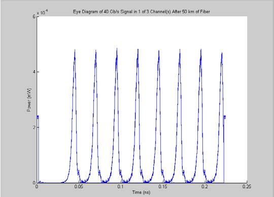
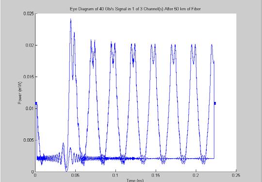
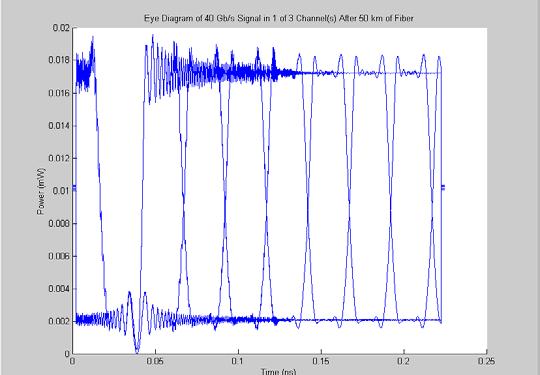
61 Figure 6-9 Eye-diagram after 50km of transmission in DCF fiber 60

62 Another simulation, which more effectively demonstrates the CS-RZ modulation format s higher nonlinear tolerance at 40Gbps uses 5km long of single mode fibre. The signals are transmitted with increasing fiber input powers and the consequence of this channel power amplification on system performance is investigated. The results are shown on Figure Figure km of SMF with amplification CS-RZ Signal transmission over 61

63 The first frame shows the eye diagram of the transmission over 5km of SMF without amplification. This is the same as in Figure 6-8(a). Initially, the peak power amplitude for a 1 bit is 4µW. Then the signal is amplified by 18dB and this is shown on the second frame of the figure. As the power of the signal increases, the effects of nonlinearity become more apparent. Therefore, signal distortion observed in the Figure is due to these nonlinear effects, namely XPM and SPM, which are included in the propagation model. Initial signal powers without amplification are about 100 times (that is 20dB) smaller for CS-RZ than for conventional RZ and NRZ. Figure 6-11 RZ Signal transmission over 5km of SMF with amplification 62

64 Figure 6-12 NRZ Signal transmission over 5km of SMF with amplification At all order of magnitude intensities investigated here, from a few µw up to 5-6mW, CS-RZ shows the greatest tolerance for nonlinear effects. This can be seen from the opening of the eyes. CS-RZ has the most open and well defined eye-diagram with the best noise margin value. 6.6 Concluding remarks It has been shown by numerical simulation, that CS-RZ modulation has been successfully implemented in the design. Its high nonlinear tolerance has been demonstrated and expected results confirmed. It is recommended not to use input channel powers greater than the threshold value of around 10mW as other unwanted nonlinear effects will come into action, that would otherwise be suppressed. 63
Lecture 6 Fiber Optical Communication Lecture 6, Slide 1
 Lecture 6 Optical transmitters Photon processes in light matter interaction Lasers Lasing conditions The rate equations CW operation Modulation response Noise Light emitting diodes (LED) Power Modulation
Analysis of Self Phase Modulation Fiber nonlinearity in Optical Transmission System with Dispersion
 36 Analysis of Self Phase Modulation Fiber nonlinearity in Optical Transmission System with Dispersion Supreet Singh 1, Kulwinder Singh 2 1 Department of Electronics and Communication Engineering, Punjabi
Department of Electrical and Computer Systems Engineering
 Department of Electrical and Computer Systems Engineering Technical Report MECSE-25-2004 Multi-level Linecoding for Ultra-high Speed Long-haul Optical Fibre Communications Systems LN Binh and D. Perera
Department of Electrical and Computer Systems Engineering
 Department of Electrical and Computer Systems Engineering Technical Report MECSE-2-2005 MOCSS2004: Monash Optical Communication System Simulator for Optically Amplified DWDM Advanced Modulation Formats
Optical Amplifiers Photonics and Integrated Optics (ELEC-E3240) Zhipei Sun Photonics Group Department of Micro- and Nanosciences Aalto University
 Zhipei Sun Photonics Group Department of Micro- and Nanosciences Aalto University") Photonics Group Department of Micro- and Nanosciences Aalto University Optical Amplifiers Photonics and Integrated Optics (ELEC-E3240) Zhipei Sun Last Lecture Topics Course introduction Ray optics & optical
Photonics Group Department of Micro- and Nanosciences Aalto University Optical Amplifiers Photonics and Integrated Optics (ELEC-E3240) Zhipei Sun Last Lecture Topics Course introduction Ray optics & optical
π code 0 Changchun,130000,China Key Laboratory of National Defense.Changchun,130000,China Keywords:DPSK; CSRZ; atmospheric channel
 4th International Conference on Computer, Mechatronics, Control and Electronic Engineering (ICCMCEE 2015) Differential phase shift keying in the research on the effects of type pattern of space optical
Fiber-Optic Communication Systems
 Fiber-Optic Communication Systems Second Edition GOVIND P. AGRAWAL The Institute of Optics University of Rochester Rochester, NY A WILEY-iNTERSCIENCE PUBLICATION JOHN WILEY & SONS, INC. NEW YORK / CHICHESTER
Performance Evaluation of 32 Channel DWDM System Using Dispersion Compensation Unit at Different Bit Rates
 Performance Evaluation of 32 Channel DWDM System Using Dispersion Compensation Unit at Different Bit Rates Simarpreet Kaur Gill 1, Gurinder Kaur 2 1Mtech Student, ECE Department, Rayat- Bahra University,
FWM Suppression in WDM Systems Using Advanced Modulation Formats
 FWM Suppression in WDM Systems Using Advanced Modulation Formats M.M. Ibrahim (eng.mohamed.ibrahim@gmail.com) and Moustafa H. Aly (drmosaly@gmail.com) OSA Member Arab Academy for Science, Technology and
Department of Electrical and Computer Systems Engineering
 Department of Electrical and Computer Systems Engineering Technical Report MECSE-4-2005 DWDM Optically Amplified Transmission Systems - SIMULINK Models and Test-Bed: Part III DPSK L.N. Binh and Y.L.Cheung
All-Optical Signal Processing and Optical Regeneration
 1/36 All-Optical Signal Processing and Optical Regeneration Govind P. Agrawal Institute of Optics University of Rochester Rochester, NY 14627 c 2007 G. P. Agrawal Outline Introduction Major Nonlinear Effects
Study of Multiwavelength Fiber Laser in a Highly Nonlinear Fiber
 Study of Multiwavelength Fiber Laser in a Highly Nonlinear Fiber I. H. M. Nadzar 1 and N. A.Awang 1* 1 Faculty of Science, Technology and Human Development, Universiti Tun Hussein Onn Malaysia, Johor,
Department of Electrical and Computer Systems Engineering
 Department of Electrical and Computer Systems Engineering Technical Report MECSE-4-006 40Gb/s Amplitude and Phase Modulation Optical Fibre Transmission Systems L.N. Binh, H.S. Tiong and T.L. Huynh 40Gb/s
Performance Limitations of WDM Optical Transmission System Due to Cross-Phase Modulation in Presence of Chromatic Dispersion
 Performance Limitations of WDM Optical Transmission System Due to Cross-Phase Modulation in Presence of Chromatic Dispersion M. A. Khayer Azad and M. S. Islam Institute of Information and Communication
Optical Complex Spectrum Analyzer (OCSA)
") Optical Complex Spectrum Analyzer (OCSA) First version 24/11/2005 Last Update 05/06/2013 Distribution in the UK & Ireland Characterisation, Measurement & Analysis Lambda Photometrics Limited Lambda House
Optical Complex Spectrum Analyzer (OCSA) First version 24/11/2005 Last Update 05/06/2013 Distribution in the UK & Ireland Characterisation, Measurement & Analysis Lambda Photometrics Limited Lambda House
Available online at ScienceDirect. Procedia Computer Science 93 (2016 )
") Available online at www.sciencedirect.com ScienceDirect Procedia Computer Science 93 (016 ) 647 654 6th International Conference On Advances In Computing & Communications, ICACC 016, 6-8 September 016,
Available online at www.sciencedirect.com ScienceDirect Procedia Computer Science 93 (016 ) 647 654 6th International Conference On Advances In Computing & Communications, ICACC 016, 6-8 September 016,
Chirped Bragg Grating Dispersion Compensation in Dense Wavelength Division Multiplexing Optical Long-Haul Networks
 363 Chirped Bragg Grating Dispersion Compensation in Dense Wavelength Division Multiplexing Optical Long-Haul Networks CHAOUI Fahd 3, HAJAJI Anas 1, AGHZOUT Otman 2,4, CHAKKOUR Mounia 3, EL YAKHLOUFI Mounir
Signal Conditioning Parameters for OOFDM System
 Chapter 4 Signal Conditioning Parameters for OOFDM System 4.1 Introduction The idea of SDR has been proposed for wireless transmission in 1980. Instead of relying on dedicated hardware, the network has
Optodevice Data Book ODE I. Rev.9 Mar Opnext Japan, Inc.
 Optodevice Data Book ODE-408-001I Rev.9 Mar. 2003 Opnext Japan, Inc. Section 1 Operating Principles 1.1 Operating Principles of Laser Diodes (LDs) and Infrared Emitting Diodes (IREDs) 1.1.1 Emitting Principles
A NOVEL SCHEME FOR OPTICAL MILLIMETER WAVE GENERATION USING MZM
 A NOVEL SCHEME FOR OPTICAL MILLIMETER WAVE GENERATION USING MZM Poomari S. and Arvind Chakrapani Department of Electronics and Communication Engineering, Karpagam College of Engineering, Coimbatore, Tamil
RADIO-OVER-FIBER TRANSPORT SYSTEMS BASED ON DFB LD WITH MAIN AND 1 SIDE MODES INJECTION-LOCKED TECHNIQUE
 Progress In Electromagnetics Research Letters, Vol. 7, 25 33, 2009 RADIO-OVER-FIBER TRANSPORT SYSTEMS BASED ON DFB LD WITH MAIN AND 1 SIDE MODES INJECTION-LOCKED TECHNIQUE H.-H. Lu, C.-Y. Li, C.-H. Lee,
SHF Communication Technologies AG
 SHF Communication Technologies AG Wilhelm-von-Siemens-Str. 23 Aufgang D 12277 Berlin Marienfelde Germany Phone ++49 30 / 772 05 10 Fax ++49 30 / 753 10 78 E-Mail: sales@shf.biz Web: http://www.shf.biz
Optical Communications and Networking 朱祖勍. Sept. 25, 2017
 Optical Communications and Networking Sept. 25, 2017 Lecture 4: Signal Propagation in Fiber 1 Nonlinear Effects The assumption of linearity may not always be valid. Nonlinear effects are all related to
Performance Analysis Of Hybrid Optical OFDM System With High Order Dispersion Compensation
 Performance Analysis Of Hybrid Optical OFDM System With High Order Dispersion Compensation Manpreet Singh Student, University College of Engineering, Punjabi University, Patiala, India. Abstract Orthogonal
Lecture 7 Fiber Optical Communication Lecture 7, Slide 1
 Dispersion management Lecture 7 Dispersion compensating fibers (DCF) Fiber Bragg gratings (FBG) Dispersion-equalizing filters Optical phase conjugation (OPC) Electronic dispersion compensation (EDC) Fiber
ECEN689: Special Topics in Optical Interconnects Circuits and Systems Spring 2016
 ECEN689: Special Topics in Optical Interconnects Circuits and Systems Spring 016 Lecture 7: Transmitter Analysis Sam Palermo Analog & Mixed-Signal Center Texas A&M University Optical Modulation Techniques
SIMULATIVE INVESTIGATION OF SINGLE-TONE ROF SYSTEM USING VARIOUS DUOBINARY MODULATION FORMATS
 SIMULATIVE INVESTIGATION OF SINGLE-TONE ROF SYSTEM USING VARIOUS DUOBINARY MODULATION FORMATS Namita Kathpal 1 and Amit Kumar Garg 2 1,2 Department of Electronics & Communication Engineering, Deenbandhu
DIRECT MODULATION WITH SIDE-MODE INJECTION IN OPTICAL CATV TRANSPORT SYSTEMS
 Progress In Electromagnetics Research Letters, Vol. 11, 73 82, 2009 DIRECT MODULATION WITH SIDE-MODE INJECTION IN OPTICAL CATV TRANSPORT SYSTEMS W.-J. Ho, H.-H. Lu, C.-H. Chang, W.-Y. Lin, and H.-S. Su
Introduction Fundamentals of laser Types of lasers Semiconductor lasers
 ECE 5368 Introduction Fundamentals of laser Types of lasers Semiconductor lasers Introduction Fundamentals of laser Types of lasers Semiconductor lasers How many types of lasers? Many many depending on
Phase Modulator for Higher Order Dispersion Compensation in Optical OFDM System
 Phase Modulator for Higher Order Dispersion Compensation in Optical OFDM System Manpreet Singh 1, Karamjit Kaur 2 Student, University College of Engineering, Punjabi University, Patiala, India 1. Assistant
Simulative Analysis of 40 Gbps DWDM System Using Combination of Hybrid Modulators and Optical Filters for Suppression of Four-Wave Mixing
 Vol.9, No.7 (2016), pp.213-220 http://dx.doi.org/10.14257/ijsip.2016.9.7.18 Simulative Analysis of 40 Gbps DWDM System Using Combination of Hybrid Modulators and Optical Filters for Suppression of Four-Wave
Wavelength Interleaving Based Dispersion Tolerant RoF System with Double Sideband Carrier Suppression
 Wavelength Interleaving Based Dispersion Tolerant RoF System with Double Sideband Carrier Suppression Hilal Ahmad Sheikh 1, Anurag Sharma 2 1 (Dept. of Electronics & Communication, CTITR, Jalandhar, India)
High-Speed Optical Modulators and Photonic Sideband Management
 114 High-Speed Optical Modulators and Photonic Sideband Management Tetsuya Kawanishi National Institute of Information and Communications Technology 4-2-1 Nukui-Kita, Koganei, Tokyo, Japan Tel: 81-42-327-7490;
LASER Transmitters 1 OBJECTIVE 2 PRE-LAB
 LASER Transmitters 1 OBJECTIVE Investigate the L-I curves and spectrum of a FP Laser and observe the effects of different cavity characteristics. Learn to perform parameter sweeps in OptiSystem. 2 PRE-LAB
Lecture 8 Fiber Optical Communication Lecture 8, Slide 1
 Lecture 8 Bit error rate The Q value Receiver sensitivity Sensitivity degradation Extinction ratio RIN Timing jitter Chirp Forward error correction Fiber Optical Communication Lecture 8, Slide Bit error
Optical Fibers p. 1 Basic Concepts p. 1 Step-Index Fibers p. 2 Graded-Index Fibers p. 4 Design and Fabrication p. 6 Silica Fibers p.
 Preface p. xiii Optical Fibers p. 1 Basic Concepts p. 1 Step-Index Fibers p. 2 Graded-Index Fibers p. 4 Design and Fabrication p. 6 Silica Fibers p. 6 Plastic Optical Fibers p. 9 Microstructure Optical
Elements of Optical Networking
 Bruckner Elements of Optical Networking Basics and practice of optical data communication With 217 Figures, 13 Tables and 93 Exercises Translated by Patricia Joliet VIEWEG+ TEUBNER VII Content Preface
Department of Electrical and Computer Systems Engineering
 Department of Electrical and Computer Systems Engineering Technical Report MECSE-5-2005 SIMULINK Models for Advanced Optical Communications: Part IV- DQPSK Modulation Format L.N. Binh and B. Laville SIMULINK
Basic concepts. Optical Sources (b) Optical Sources (a) Requirements for light sources (b) Requirements for light sources (a)
 Optical Sources (a) Requirements for light sources (b) Requirements for light sources (a)") Optical Sources (a) Optical Sources (b) The main light sources used with fibre optic systems are: Light-emitting diodes (LEDs) Semiconductor lasers (diode lasers) Fibre laser and other compact solid-state
Optical Sources (a) Optical Sources (b) The main light sources used with fibre optic systems are: Light-emitting diodes (LEDs) Semiconductor lasers (diode lasers) Fibre laser and other compact solid-state
Performance Analysis of SOA-MZI based All-Optical AND & XOR Gate
 International Journal of Current Engineering and Technology E-ISSN 2277 4106, P-ISSN 2347 5161 2016 INPRESSCO, All Rights Reserved Available at http://inpressco.com/category/ijcet Research Article Utkarsh
Analyzing the Non-Linear Effects in DWDM Optical Network Using MDRZ Modulation Format
 Analyzing the Non-Linear Effects in DWDM Optical Network Using MDRZ Modulation Format Ami R. Lavingia Electronics & Communication Dept. SAL Institute of Technology & Engineering Research Gujarat Technological
Optical Digital Transmission Systems. Xavier Fernando ADROIT Lab Ryerson University
 Optical Digital Transmission Systems Xavier Fernando ADROIT Lab Ryerson University Overview In this section we cover point-to-point digital transmission link design issues (Ch8): Link power budget calculations
Design of Ultra High Capacity DWDM System with Different Modulation Formats
 Design of Ultra High Capacity DWDM System with Different Modulation Formats A. Nandhini 1, K. Gokulakrishnan 2 1 PG Scholar, Department of Electronics & Communication Engineering, Regional Center, Anna
Chapter 8. Wavelength-Division Multiplexing (WDM) Part II: Amplifiers
 Part II: Amplifiers") Chapter 8 Wavelength-Division Multiplexing (WDM) Part II: Amplifiers Introduction Traditionally, when setting up an optical link, one formulates a power budget and adds repeaters when the path loss exceeds
Chapter 8 Wavelength-Division Multiplexing (WDM) Part II: Amplifiers Introduction Traditionally, when setting up an optical link, one formulates a power budget and adds repeaters when the path loss exceeds
Modulation of light. Direct modulation of sources Electro-absorption (EA) modulators
 modulators") Modulation of light Direct modulation of sources Electro-absorption (EA) modulators Why Modulation A communication link is established by transmission of information reliably Optical modulation is embedding
Modulation of light Direct modulation of sources Electro-absorption (EA) modulators Why Modulation A communication link is established by transmission of information reliably Optical modulation is embedding
Performance Analysis of Gb/s DWDM Metropolitan Area Network using SMF-28 and MetroCor Optical Fibres
 Research Cell: An International Journal of Engineering Sciences ISSN: 2229-6913 Issue Sept 2011, Vol. 4 11 Performance Analysis of 32 2.5 Gb/s DWDM Metropolitan Area Network using SMF-28 and MetroCor Optical
Chapter 8. Digital Links
 Chapter 8 Digital Links Point-to-point Links Link Power Budget Rise-time Budget Power Penalties Dispersions Noise Content Photonic Digital Link Analysis & Design Point-to-Point Link Requirement: - Data
Module 16 : Integrated Optics I
 Module 16 : Integrated Optics I Lecture : Integrated Optics I Objectives In this lecture you will learn the following Introduction Electro-Optic Effect Optical Phase Modulator Optical Amplitude Modulator
UNIT - 7 WDM CONCEPTS AND COMPONENTS
 UNIT - 7 WDM CONCEPTS AND COMPONENTS WDM concepts, overview of WDM operation principles, WDM standards, Mach-Zehender interferometer, multiplexer, Isolators and circulators, direct thin film filters, active
Spectrally Compact Optical Subcarrier Multiplexing with 42.6 Gbit/s AM-PSK Payload and 2.5Gbit/s NRZ Labels
 Spectrally Compact Optical Subcarrier Multiplexing with 42.6 Gbit/s AM-PSK Payload and 2.5Gbit/s NRZ Labels A.K. Mishra (1), A.D. Ellis (1), D. Cotter (1),F. Smyth (2), E. Connolly (2), L.P. Barry (2)
S Optical Networks Course Lecture 2: Essential Building Blocks
 S-72.3340 Optical Networks Course Lecture 2: Essential Building Blocks Edward Mutafungwa Communications Laboratory, Helsinki University of Technology, P. O. Box 2300, FIN-02015 TKK, Finland Tel: +358 9
CHAPTER 4 RESULTS. 4.1 Introduction
 CHAPTER 4 RESULTS 4.1 Introduction In this chapter focus are given more on WDM system. The results which are obtained mainly from the simulation work are presented. In simulation analysis, the study will
LASER DIODE MODULATION AND NOISE
 > 5' O ft I o Vi LASER DIODE MODULATION AND NOISE K. Petermann lnstitutfiir Hochfrequenztechnik, Technische Universitdt Berlin Kluwer Academic Publishers i Dordrecht / Boston / London KTK Scientific Publishers
S Optical Networks Course Lecture 4: Transmission System Engineering
 S-72.3340 Optical Networks Course Lecture 4: Transmission System Engineering Edward Mutafungwa Communications Laboratory, Helsinki University of Technology, P. O. Box 2300, FIN-02015 TKK, Finland Tel:
Broadcast and distribution networks
 4/7/06 SYSTEM ARCHITECTURES Point-to-point links Point-to-point links constitute the simplest kind of lightwave systems The link length can vary from less than a kilometer (short haul) to thousands of
Chapter 1 Introduction
 Chapter 1 Introduction 1-1 Preface Telecommunication lasers have evolved substantially since the introduction of the early AlGaAs-based semiconductor lasers in the late 1970s suitable for transmitting
Next-Generation Optical Fiber Network Communication
 Next-Generation Optical Fiber Network Communication Naveen Panwar; Pankaj Kumar & manupanwar46@gmail.com & chandra.pankaj30@gmail.com ABSTRACT: In all over the world, much higher order off modulation formats
RZ BASED DISPERSION COMPENSATION TECHNIQUE IN DWDM SYSTEM FOR BROADBAND SPECTRUM
 RZ BASED DISPERSION COMPENSATION TECHNIQUE IN DWDM SYSTEM FOR BROADBAND SPECTRUM Prof. Muthumani 1, Mr. Ayyanar 2 1 Professor and HOD, 2 UG Student, Department of Electronics and Communication Engineering,
WDM Concept and Components. EE 8114 Course Notes
 WDM Concept and Components EE 8114 Course Notes Part 1: WDM Concept Evolution of the Technology Why WDM? Capacity upgrade of existing fiber networks (without adding fibers) Transparency:Each optical channel
To investigate effects of extinction ratio on SOA based wavelength Converters for all Optical Networks
 289 To investigate effects of extinction ratio on SOA based wavelength Converters for all Optical Networks Areet Aulakh 1, Kulwinder Singh Malhi 2 1 Student, M.Tech, ECE department, Punjabi University,
Comparison between DWDM Transmission Systems over SMF and NZDSF with 25 40Gb/s signals and 50GHz Channel Spacing
 Comparison between DWDM Transmission Systems over SMF and NZDSF with 25 4Gb/s signals and 5GHz Channel Spacing Ruben Luís, Daniel Fonseca, Adolfo V. T. Cartaxo Abstract The use of new types of fibre with
Optimisation of DSF and SOA based Phase Conjugators. by Incorporating Noise-Suppressing Fibre Gratings
 Optimisation of DSF and SOA based Phase Conjugators by Incorporating Noise-Suppressing Fibre Gratings Paper no: 1471 S. Y. Set, H. Geiger, R. I. Laming, M. J. Cole and L. Reekie Optoelectronics Research
Performance Analysis of dispersion compensation using Fiber Bragg Grating (FBG) in Optical Communication
 in Optical Communication") Research Article International Journal of Current Engineering and Technology E-ISSN 2277 416, P-ISSN 2347-5161 214 INPRESSCO, All Rights Reserved Available at http://inpressco.com/category/ijcet Performance
Research Article International Journal of Current Engineering and Technology E-ISSN 2277 416, P-ISSN 2347-5161 214 INPRESSCO, All Rights Reserved Available at http://inpressco.com/category/ijcet Performance
Table 10.2 Sensitivity of asynchronous receivers. Modulation Format Bit-Error Rate N p. 1 2 FSK heterodyne. ASK heterodyne. exp( ηn p /2) 40 40
 40 40") 10.5. SENSITIVITY DEGRADATION 497 Table 10.2 Sensitivity of asynchronous receivers Modulation Format Bit-Error Rate N p N p ASK heterodyne 1 2 exp( ηn p /4) 80 40 FSK heterodyne 1 2 exp( ηn p /2) 40 40
10.5. SENSITIVITY DEGRADATION 497 Table 10.2 Sensitivity of asynchronous receivers Modulation Format Bit-Error Rate N p N p ASK heterodyne 1 2 exp( ηn p /4) 80 40 FSK heterodyne 1 2 exp( ηn p /2) 40 40
DWDM FILTERS; DESIGN AND IMPLEMENTATION
 DWDM FILTERS; DESIGN AND IMPLEMENTATION 1 OSI REFERENCE MODEL PHYSICAL OPTICAL FILTERS FOR DWDM SYSTEMS 2 AGENDA POINTS NEED CHARACTERISTICS CHARACTERISTICS CLASSIFICATION TYPES PRINCIPLES BRAGG GRATINGS
Performance Analysis Of An Ultra High Capacity 1 Tbps DWDM-RoF System For Very Narrow Channel Spacing
 Performance Analysis Of An Ultra High Capacity 1 Tbps DWDM-RoF System For Very Narrow Channel Spacing Viyoma Sarup* and Amit Gupta Chandigarh University Punjab, India *viyoma123@gmail.com Abstract A RoF
Prabhjeet Singh a, Narwant Singh b, Amandeep Singh c
 ISSN : 2250-3021 Investigation of DWDM System for Different Modulation Formats Prabhjeet Singh a, Narwant Singh b, Amandeep Singh c a B.G.I.E.T. Sangrur, India b G.N.D.E.C. Ludhiana, India c R.I.E.T, Ropar,
Department of Electrical and Computer Systems Engineering
 Department of Electrical and Computer Systems Engineering Technical Report MECSE-3-2005 DWDM Advanced Optical Communication Simulink Models: Part I Optical Spectra L.N Binh and Y.L. Cheung DWDM ADVANCED
Examination Optoelectronic Communication Technology. April 11, Name: Student ID number: OCT1 1: OCT 2: OCT 3: OCT 4: Total: Grade:
 Examination Optoelectronic Communication Technology April, 26 Name: Student ID number: OCT : OCT 2: OCT 3: OCT 4: Total: Grade: Declaration of Consent I hereby agree to have my exam results published on
WDM Transmitter Based on Spectral Slicing of Similariton Spectrum
 WDM Transmitter Based on Spectral Slicing of Similariton Spectrum Leila Graini and Kaddour Saouchi Laboratory of Study and Research in Instrumentation and Communication of Annaba (LERICA), Department of
Optical Transport Tutorial
 Optical Transport Tutorial 4 February 2015 2015 OpticalCloudInfra Proprietary 1 Content Optical Transport Basics Assessment of Optical Communication Quality Bit Error Rate and Q Factor Wavelength Division
Flat Frequency Comb Generation Based on Efficiently Multiple Four-Wave Mixing Without Polarization Control
 PHOTONIC SENSORS / Vol. 6, No. 1, 216: 85 89 Flat Frequency Comb Generation Based on Efficiently Multiple Four-Wave Mixing Without Polarization Control Qimeng DONG, Bao SUN *, Fushen CHEN, and Jun JIANG
S-band gain-clamped grating-based erbiumdoped fiber amplifier by forward optical feedback technique
 S-band gain-clamped grating-based erbiumdoped fiber amplifier by forward optical feedback technique Chien-Hung Yeh 1, *, Ming-Ching Lin 3, Ting-Tsan Huang 2, Kuei-Chu Hsu 2 Cheng-Hao Ko 2, and Sien Chi
ANALYSIS OF DISPERSION COMPENSATION IN A SINGLE MODE OPTICAL FIBER COMMUNICATION SYSTEM
 ANAYSIS OF DISPERSION COMPENSATION IN A SINGE MODE OPTICA FIBER COMMUNICATION SYSTEM Sani Abdullahi Mohammed 1, Engr. Yahya Adamu and Engr. Matthew Kwatri uka 3 1,,3 Department of Electrical and Electronics
Chapter 1. Overview. 1.1 Introduction
 1 Chapter 1 Overview 1.1 Introduction The modulation of the intensity of optical waves has been extensively studied over the past few decades and forms the basis of almost all of the information applications
Lecture 9 External Modulators and Detectors
 Optical Fibres and Telecommunications Lecture 9 External Modulators and Detectors Introduction Where are we? A look at some real laser diodes. External modulators Mach-Zender Electro-absorption modulators
Table of Contents. Abbrevation Glossary... xvii
 Table of Contents Preface... xiii Abbrevation Glossary... xvii Chapter 1 General Points... 1 1.1. Microwave photonic links... 1 1.2. Link description... 4 1.3. Signal to transmit... 5 1.3.1. Microwave
PERFORMANCE ANALYSIS OF WDM AND EDFA IN C-BAND FOR OPTICAL COMMUNICATION SYSTEM
 www.arpapress.com/volumes/vol13issue1/ijrras_13_1_26.pdf PERFORMANCE ANALYSIS OF WDM AND EDFA IN C-BAND FOR OPTICAL COMMUNICATION SYSTEM M.M. Ismail, M.A. Othman, H.A. Sulaiman, M.H. Misran & M.A. Meor
OPTICAL COMMUNICATIONS S
 OPTICAL COMMUNICATIONS S-108.3110 1 Course program 1. Introduction and Optical Fibers 2. Nonlinear Effects in Optical Fibers 3. Fiber-Optic Components 4. Transmitters and Receivers 5. Fiber-Optic Measurements
Absorption: in an OF, the loss of Optical power, resulting from conversion of that power into heat.
 Absorption: in an OF, the loss of Optical power, resulting from conversion of that power into heat. Scattering: The changes in direction of light confined within an OF, occurring due to imperfection in
Optoelectronic Oscillator Topologies based on Resonant Tunneling Diode Fiber Optic Links
 Optoelectronic Oscillator Topologies based on Resonant Tunneling Diode Fiber Optic Links Bruno Romeira* a, José M. L Figueiredo a, Kris Seunarine b, Charles N. Ironside b, a Department of Physics, CEOT,
FIBER OPTICS. Prof. R.K. Shevgaonkar. Department of Electrical Engineering. Indian Institute of Technology, Bombay. Lecture: 37
 FIBER OPTICS Prof. R.K. Shevgaonkar Department of Electrical Engineering Indian Institute of Technology, Bombay Lecture: 37 Introduction to Raman Amplifiers Fiber Optics, Prof. R.K. Shevgaonkar, Dept.
CHAPTER 3 PERFORMANCE OF MODULATION FORMATS ON DWDM OPTICAL SYSTEMS
 67 CHAPTER 3 PERFORMANCE OF MODULATION FORMATS ON DWDM OPTICAL SYSTEMS 3.1 INTRODUCTION The need for higher transmission rate in Dense Wavelength Division optical systems necessitates the selection of
UNIVERSITY OF TORONTO FACULTY OF APPLIED SCIENCE AND ENGINEERING. FINAL EXAMINATION, April 2017 DURATION: 2.5 hours
 UNIVERSITY OF TORONTO FACULTY OF APPLIED SCIENCE AND ENGINEERING ECE4691-111 S - FINAL EXAMINATION, April 2017 DURATION: 2.5 hours Optical Communication and Networks Calculator Type: 2 Exam Type: X Examiner:
SUBMARINE SYSTEM UPGRADES WITH 25 GHZ CHANNEL SPACING USING DRZ AND RZ-DPSK MODULATION FORMATS
 SUBMARINE SYSTEM UPGRADES WITH 25 GHZ CHANNEL SPACING USING DRZ AND RZ-DPSK MODULATION FORMATS Jiping Wen, Chunmei Yu, Tiegang Zhou, Xiaoyan Fan, Liping Ma (Huawei Marine Networks Co Ltd) Email:
40Gb/s Optical Transmission System Testbed
 The University of Kansas Technical Report 40Gb/s Optical Transmission System Testbed Ron Hui, Sen Zhang, Ashvini Ganesh, Chris Allen and Ken Demarest ITTC-FY2004-TR-22738-01 January 2004 Sponsor: Sprint
MICROWAVE photonics is an interdisciplinary area
 314 JOURNAL OF LIGHTWAVE TECHNOLOGY, VOL. 27, NO. 3, FEBRUARY 1, 2009 Microwave Photonics Jianping Yao, Senior Member, IEEE, Member, OSA (Invited Tutorial) Abstract Broadband and low loss capability of
Digital Optical. Communications. Le Nguyen Binh. CRC Press Taylor &. Francis Group. Boca Raton London New York
 Digital Optical Communications Le Nguyen Binh CRC Press Taylor &. Francis Group Boca Raton London New York CRC Press is an imprint of the Taylor & Francis Group, an informa business Contents Preface Acknowledgments
Suppression of Four Wave Mixing Based on the Pairing Combinations of Differently Linear-Polarized Optical Signals in WDM System
 The Quarterly Journal of Optoelectronical Nanostructures Islamic Azad University Spring 2016 / Vol. 1, No.1 Suppression of Four Wave Mixing Based on the Pairing Combinations of Differently Linear-Polarized
Performance Comparison of Pre-, Post-, and Symmetrical Dispersion Compensation for 96 x 40 Gb/s DWDM System using DCF
 Performance Comparison of Pre-, Post-, and Symmetrical Dispersion Compensation for 96 x 40 Gb/s DWDM System using Sabina #1, Manpreet Kaur *2 # M.Tech(Scholar) & Department of Electronics & Communication
Compensation of Dispersion in 10 Gbps WDM System by Using Fiber Bragg Grating
 International Journal of Computational Engineering & Management, Vol. 15 Issue 5, September 2012 www..org 16 Compensation of Dispersion in 10 Gbps WDM System by Using Fiber Bragg Grating P. K. Raghav 1,
Chapter 12: Optical Amplifiers: Erbium Doped Fiber Amplifiers (EDFAs)
") Chapter 12: Optical Amplifiers: Erbium Doped Fiber Amplifiers (EDFAs) Prof. Dr. Yaocheng SHI ( 时尧成 ) yaocheng@zju.edu.cn http://mypage.zju.edu.cn/yaocheng 1 Traditional Optical Communication System Loss
Chapter 12: Optical Amplifiers: Erbium Doped Fiber Amplifiers (EDFAs) Prof. Dr. Yaocheng SHI ( 时尧成 ) yaocheng@zju.edu.cn http://mypage.zju.edu.cn/yaocheng 1 Traditional Optical Communication System Loss
Optical Amplifiers (Chapter 6)
") Optical Amplifiers (Chapter 6) General optical amplifier theory Semiconductor Optical Amplifier (SOA) Raman Amplifiers Erbium-doped Fiber Amplifiers (EDFA) Read Chapter 6, pp. 226-266 Loss & dispersion
Optical Amplifiers (Chapter 6) General optical amplifier theory Semiconductor Optical Amplifier (SOA) Raman Amplifiers Erbium-doped Fiber Amplifiers (EDFA) Read Chapter 6, pp. 226-266 Loss & dispersion
Advanced Optical Communications Prof. R. K. Shevgaonkar Department of Electrical Engineering Indian Institute of Technology, Bombay
 Advanced Optical Communications Prof. R. K. Shevgaonkar Department of Electrical Engineering Indian Institute of Technology, Bombay Lecture No. # 27 EDFA In the last lecture, we talked about wavelength
Rogério Nogueira Instituto de Telecomunicações Pólo de Aveiro Departamento de Física Universidade de Aveiro
 Fiber Bragg Gratings for DWDM Optical Networks Rogério Nogueira Instituto de Telecomunicações Pólo de Aveiro Departamento de Física Universidade de Aveiro Overview Introduction. Fabrication. Physical properties.
Novel High-Q Spectrum Sliced Photonic Microwave Transversal Filter Using Cascaded Fabry-Pérot Filters
 229 Novel High-Q Spectrum Sliced Photonic Microwave Transversal Filter Using Cascaded Fabry-Pérot Filters R. K. Jeyachitra 1**, Dr. (Mrs.) R. Sukanesh 2 1 Assistant Professor, Department of ECE, National
OFC SYSTEM: Design Considerations. BC Choudhary, Professor NITTTR, Sector 26, Chandigarh.
 OFC SYSTEM: Design Considerations BC Choudhary, Professor NITTTR, Sector 26, Chandigarh. OFC point-to-point Link Transmitter Electrical to Optical Conversion Coupler Optical Fiber Coupler Optical to Electrical
Comparative Analysis Of Different Dispersion Compensation Techniques On 40 Gbps Dwdm System
 INTERNATIONAL JOURNAL OF TECHNOLOGY ENHANCEMENTS AND EMERGING ENGINEERING RESEARCH, VOL 3, ISSUE 06 34 Comparative Analysis Of Different Dispersion Compensation Techniques On 40 Gbps Dwdm System Meenakshi,
All-Optical Clock Division Using Period-one Oscillation of Optically Injected Semiconductor Laser
 International Conference on Logistics Engineering, Management and Computer Science (LEMCS 2014) All-Optical Clock Division Using Period-one Oscillation of Optically Injected Semiconductor Laser Shengxiao
PERFORMANCE ENHANCEMENT OF 32 CHANNEL LONG HAUL DWDM SOLITON LINK USING ELECTRONIC DISPERSION COMPENSATION
 International Journal of Electronics, Communication & Instrumentation Engineering Research and Development (IJECIERD) ISSN 2249-684X Vol. 2 Issue 4 Dec - 2012 11-16 TJPRC Pvt. Ltd., PERFORMANCE ENHANCEMENT