Department of Electrical and Computer Systems Engineering
|
|
|
- Helena Mosley
- 5 years ago
- Views:
Transcription

1 Department of Electrical and Computer Systems Engineering Technical Report MECSE Multi-level Linecoding for Ultra-high Speed Long-haul Optical Fibre Communications Systems LN Binh and D. Perera
2 MULTI-LEVEL LINE CODING FOR ULTRA-HIGH SPEED LONG HAUL OPTICAL FIBRE COMMUNICATION SYSTEMS L. N. Binh and D. Perera Department of Electrical and Computer Systems Engineering, Monash university, Clayton Victoria 3168 Australia ABSTRACT The demands for greater spectral efficiency, higher line rate, higher channel count, greater amplifier/repeater spacing, Tb/s capacity DWDM long haul optical communication systems, efficient transmission of optical channels over long-haul optical fibre system is essential. Since the conventional Return to zero (RZ) and Non return to zero (NRZ) modulation formats suffer from dispersion and inefficient for multiplexing several channels, multi-level signaling using novel modulation formats, such as novel optical coding and carrier suppressed duobinary are studied in this paper for Tb/s capacity optical transmission systems. A comprehensive modeling platform is demonstrated and the modulation formats are described in detail. Performances of these modulation formats are analyzed against impairment factors such as fiber dispersion, fiber non linear effects, and optical power loss. We demonstrate that, novel optical coding can be used to transmit 65 x 40Gbps channels, while 81 x 40Gpbs DWDM channels can be transmitted using carrier suppressed duo binary modulation, along 100km dispersion compensated optical fibre link. The achieved spectrum efficiency for these techniques is 0.41bit/s/Hz and 0.8bit/s/Hz respectively.
3 TABLE OF CONTENTS 1. INTRODUCTION LINE CODING TECHNIQUES Introduction to line coding for optical communication systems Novel optical line code First order code Novel optical line code generation Optical Duo binary coding EXTERNAL MODULATORS AS DWDM OPTICAL TRANSMITTERS Modulation Techniques External modulation of movel optical line coded signal Carrier suppressed duo-binary modulation COMPARISION OF THE PERFORMANCE OF DIFFERENT LINE CODING TECHNIQUES Dispersion tolerance comparison Non linear tolerance measurement GHz spaced 40Gbit/s * 81 WDM transmission over 100km dispersion managed fiber using carrier suppressed optical duo-binary Coding CONCLUSIONS REFERENCES...54
4 1. INTRODUCTION Internet traffic, driven by multitude of new users and bandwidth hungry applications, is rapidly surpassing all other forms of voice and data transfer within today s communication networks. Over the past few years, the capacity of optical transmission systems has been doubling[10]. The increase in the number of channels through dense wavelength division multiplexing (DWDM), accounts for most of this evaluation. However in order to achieve even higher capacities, the channel bit rates have to be increased, e.g. 40Gb/s in commercial products, the channel spacing must be reduced and the total exploited optical bandwidth has to be enlarged, and the total exploited optical bandwidth has to be enlarged. All three factors should be investigated simultaneously to realize higher spectral efficiency and greater total throughput. Enabling technologies for high capacity (Tb/s), point to point, long distance transmission are (i) Low noise, high power, wide bandwidth and gain flattened optical amplifiers;(ii) Optimized optical fiber and associated dispersion management techniques for future proof infrastructure and transmission, which is tolerant to propagation effects (iii) Optimized line coding techniques and modulation formats for high spectral efficiency; (iv) High-speed electronics and opto electronics for the transmitter and receiver equipment;(v) Polarization mode dispersion (PMD) mitigation(vi) Dispersion compensating modules compatible with large optical bandwidths(vii) Fast optical processing for 2R 3R regeneration providing efficient but lower cost regeneration compared with back to back transmit/receive equipment(viii) Very high bit rate equipment (60Gbps and beyond), based on combination of electronic time division multiplexing (ETDM), and optical time division multiplexing (TDM)
5 techniques; (ix) New generation of forward error correction techniques to facilitate noise tolerant transmission (x) Optical filters with well defined amplitude and phase shapes for ultra narrow (narrower than the WDM channel bandwidth) filtering: Among recent advances in the field of ultrahigh capacity transmission and ultra high bit rate components are a record terrestrial Terabits per second transmission systems with high spectral efficiency, which has never been achieved before, and the recent progress in the field of 40Gbps opto electronics and electronics components, showing that a new generation of components is feasible for the practical implementation of 40Gbps transmission systems. Several developments are necessary to achieve a transmission rate of 40Gbps per channel. Opto-electronic devices and very fast integrated circuits are now available, although their high-speed capabilities often remain far from what is required. Lithium niobate external modulators are currently the lowest bandwidth components with in the transmitter. Moreover they require high drive voltage of more than 5V pp to achieve high extinction ratio. Higher bandwidths and lower driving voltages can be achieved with the more compact InP based electro absorption modulators (EAM). InGaAs PIN photodiodes offer very large bandwidths and high responsivities. In addition, they can withstand high optical input powers and often exhibits very low sensitivities. In addition to above, line coding is a vital factor in optical transmission. The performance limited by chromatic dispersion of optical transmission depends on the bandwidth of the optical signal. Line coding fits the spectrum of the data signal to the transmission channel characteristics. In conventional standard fiber transmission lines, the return to zero and non return to zero formats are the two modulation formats most often used. But when considering the factors such as spectral efficiency, power margin, tolerance against group velocity
6 dispersion and fiber non linearity effects like self phase modulation and cross phase modulation network designers has to chose alternative modulation formats such as carrier suppressed return to zero, novel optical coding, carrier suppressed duo binary at 40Gbps transmission rate. Thus the principal objectives of this paper are: (i) Modeling the novel optical coding and carrier suppressed duo binary modulation formats in MAT LAB version 6.1 platform (ii) Simulating the 40Gbps per channel optical communication system and investigating the transmission performance of the system when using novel optical coding and carrier suppressed duo binary modulation techniques with external modulator.(iii) Investigating the performance of these modulation formats against the impairment factors such as fiber dispersion, fiber non linear effects, and optical power loss.(iv) Simulating Tb/s capacity, dispersion managed long haul DWDM optical communication system using multi level modulation techniques. Line coding can be used to reduce the bandwidth of the signal to abate the signal distortion by chromatic dispersion. Partial response coding is a mode of line coding that can be realized by finite impulse response (FIR) filtering. The partial response signal is encoded into pseudo multilevel signal with the same data rate. Duo-binary coding is a simple partial response code implying low pass filtering of the signal. By using a chirp-free Mach-Zehnder modulator, the signal is AM-PSK modulated. The receiver can be a conventional binary direct detecting receiver. The other common line coding technique use multilevel signaling is the novel optical line code. Duobinay is a special case of order one novel optical line code, and the latter use four
7 levels instead of the three levels of duo binary. In this paper work, the use of these multilevel modulation formats in Tb/s transmission rates is discussed in detail. In this paper the performance of order one novel optical line code and duo-binary coding, in highly dispersive fiber is compared with the conventional return to zero (RZ) and non return to zero (NRZ) line coding techniques. Dispersion compensation techniques and non-linear tolerance is discussed for the interested coding techniques. Finally multi channel transmission using DWDM technique along a dispersion compensated fiber optic link is illustrated. The report is organized as follows. In section two, line-coding techniques are introduced with a special attention to the novel optical line coding and duo-binary line coding. Analytical methods used to develop software coding are also discussed in detail. Section three describes the optical transmitters and modulation characteristics of light sources and biasing management of Mach Zehnder modulators for multilevel modulation. Factors to be considered for the design of optical fiber communication system are illustrated in section four. Section five gives the performance comparison of RZ, NRZ and multi-level optical coding and carrier suppressed duo binary modulation technique. Finally concluding remarks of the paper are given. 2. LINE CODING TECHNIQUES 2.1 An introduction to line coding for optical communication systems The rapid worldwide growing of data and Internet traffic in telecommunication networks results in a sharp increase in the demand for transmission capacity. Thus more efficient utilization of the existing optical fiber network is an answer that meets economical
8 constraints. An important step is an introduction of optical communication systems with terabits per second capacity, which are based on DWDM technology. Thus for the first time bandwidth efficiency, which is an important feature in wireless communication has become an important issue in fiber optics. There are several approaches to achieve overall bandwidth efficiency. Amongst them are improved modulation format, line-coding techniques, management of chromatic and polarization mode dispersion including equalization, wideband optical amplifiers, improved WDM multiplexes and demultiplexes. Modeling of the WDM optical channel including nonlinear effects is necessary in order to investigate the impact of the various methods. For practical reasons it is important (to avoid high complexity algorithms) to end up with structures that are realizable at these high frequencies. Therefore research engineers focus mainly on bandwidth efficient modulation formats at channel data rates 40Gbps. By saving bandwidth both the dispersion problems and the channel density are improved. A promising approach is multilevel signal line coding. The popular line coding formats such as RZ and NRZ are worked well up to 10Gbps per channel long haul high-speed optical communication networks. Recent analysis and investigations have shown that RZ turned out to be superior compared to conventional NRZ systems, at least as long as standard single mode fibers are used as transmission media. The RZ format has been reported to be effective against self phase modulation (SPM) in standard single mode fiber links. [4] SPM resulting from fiber non-linearities caused by group velocity dispersion (GVD) leads to waveform distortion that limits the maximum transmission distance and capacity of high-speed optical links. Thus tolerance with respect to both SPM and GVD are essential for reliable network operation. On the other hand, because of the
9 narrower optical spectrum of NRZ format, NRZ enables higher spectral efficiency in wavelength division multiplexing (WDM) systems compared to RZ in the linear region. [3] However the tolerable dispersion range is limited in both RZ and NRZ modulation formats. In addition, they limit the potential distance of the signal due to the non-linearity effects of fiber, when they are used in terabit capacity optical communication networks. Data NRZ RZ Figure 1: Coding formats of NRZ and RZ In MOCSS, the carrier suppressed return to zero (CSRZ) modulation format has been used to simulate 40Gbps optical communication systems since it offers large power margin in dispersion managed transmission lines using single mode fiber (SMF) at a line rate of 40Gbps. In this section generation of multilevel coding formats such as novel optical coding and carrier suppressed duo-binary is discussed in detail. In Section 2.2 a description of novel optical coding is provided with the method of generation, while in Section 2.3 analytical method used to generate duo binary coding is discussed.
10 2.2 A multi-level novel optical line code Novel optical line coding is similar to conventional miller coding with the difference being that two of them are scaled by a factor α < 1 and transmitted in sequence according to the duobinary logic. Novel optical codes are ranging from order 1, 2.n and in MOCSS only order one novel optical codes are used First order code The first order code uses four wave forms s i (t), and the state diagram is shown in the Figure 2, where Σ 1, Σ 2 are the code status and the elementary signals s i (t), where I = 1,2,3,4 are depicted. s 1 (t) s 2 (t) s 3 (t) s 4 (t) T t α T t α t - α - α T T s 2 (t) s 1 (t) Σ 1 Σ 2 s 3 (t) s 4 (t) Figure 2:Elementary signals and coding state diagram for novel multi-level optical line code of order one [5] Elementary signals form two pairs with s 1 (t) = - s 4 (t) and s 2 (t) = - s 3 (t). In addition two of the elementary signals [s 2 (t) and s 3 (t)] are scaled by α. In MOCSS α is chosen as 0.5 to produce best spectral shape.
11 The information (data) sequence {U k } is encoded to form the coded signal. xe( t) = gk( ) se( t kt; uk σ κ ) (1) = k where σ k denotes the generic encoder state and g 1 (σ k ) is a coefficient defined by the following rule g ( t, u 1 k 1,... s1( t).. if. σ k = 1 ) = 1,... s2 ( t).. if. σ k = 2 (2) where Σ 1 and Σ 1 indicates the states allowed to the encoder, and s e (t;u k ) is one of the two elementary signals s 1 (t) or s 2 (t) selected in accordance with the following rule.[5] s1( t).. if. uk = 0 s e ( t, uk ) = (3) s2 ( t).. if. uk = 1 Hence the actual elementary signal output from the encoder will be one of s 1 (t), s 2 (t), s 3 (t), s 4 (t). The sequence of the states of the encoder is defined by the following rule. σ k + 1 = g 2 (u k, σ k ) (4) The above encoding rules are summarized in Table 1. Information Sequence(u k ) Generic state (σ k ) encoder Sequence of the state of the encoder (g 2 ) 0 Σ 1 Σ 1 s 1 (t) Encoded x e (t) 0 Σ 2 Σ 2 -s 1 (t) = s 4 (t) 1 Σ 1 Σ 2 s 2 (t) 1 Σ 2 Σ 1 -s 2 (t) = s 3 (t) Table 1: Summary of the encoding criteria for novel optical code signal
12 An example of a waveform generated by the order one code with = 0.5 is shown in the Figure 3. Data Novel optical coded signal (order one) Figure 3: novel optical coded signal Novel optical line code generation Elementary signals of order one code can be generated by expressing four elementary signals of figure 2 as linear combinations of the rectangular pulses of duration T/2. 1,.0 < t < T / 2 p( t) = (5) 1, elsewhere Therefore, the elementary signals can be defined as : s 1 (t) = p(t) + p(t T/2); s 2 (t) = 0.5[p(t) p(t - T/2); s 3 (t) = -s 2 (t); s 4 (t) = -s 1 (t) with T is the bit period of the data sequence. In Matlab codes p(t) is defined as p(t) = [1 exp(-t/t rise ) 2 ] and p(t-t/2) is defined as p(t T/2) = [exp(- t/t rise ) 2.with t rise is the circuit rise time. Circuit rise time determines the 3dB modulation band width. The four basic factors that limit the system speed are the transmitter rise time, the material and modal dispersion rise time of the fiber transmission link, and the receiver rise time. In MOCSS modulation bandwidth of the external modulator is taken as 30GHz and the rise time of novel optical order one code is
13 trise = (6) Modulationbandwidth Figure 4 shows the novel optical coded (order one) signal obtained from MOCSS software package and its power spectrum calculated from the discrete Fourier transform of the modulating voltage waveform as 1 N 2 ( jϖ ) I ( jϖ Pn e = m e ) (7) Where I m (e jω ) is the modulating signal in the frequency domain and N is the number of samples in a sequence of discreet time waveforms Figure 4: Novel optical coded electrical modulating signal of and its power spectrum (from MOCSS)
14 2.3 Optical Duo-binary coding The duo binary coding format is intended to increase the data transmission is intended to increase the data transmission efficiency by means of coding. According to A. Lender who discovered the concept of correlative transmission techniques, duo means doubling the binary capacity by bandwidth compression. It takes the advantage of all the three possible amplitude levels: the mark state is represented by the zero (or center) level; the space state is represented by either by a positive (or top) or a negative (or bottom) level. This scheme assures that the only permitted transitions in successive bits are between any two adjacent symbols. These patterns follow the unique rule; the polarities of two successive bits at the extreme levels are opposite. Data Duobinary Modified Duobinary Figure 5 Duo-binary coded signal and modified duo binary coded signal The modified duo binary is another partial response signaling (PRS) scheme that involves a correlation span of two digits. It is a DC free format and also has three levels. The pulse train is divided odd and even bits. Both odd and even pulse trains follow the same rule: two successive bits at the extreme levels always have opposite polarity [6]. Contrary to duo binary case transition from top level to the bottom one or vice versa can occur. As a consequence, the width of the eye pattern diagram is narrower, which indicates an increase
15 inter symbol interference (ISI). As well as duo binary modified duo binary allows a 2:1 bandwidth compression. The duo binary line code can be generated with three elementary signals shown in Figure 6. s 1 (t) s 2 (t) s 3 (t) T t T t T t Figure 6: Elementary signal for duo binary line code Elementary signals s 1 (t) and s 3 (t) can be expressed as a linear combination of rectangular pulses of duration T/2 1,.0 < t < T / 2 p( t) = (8) 1, elsewhere Then the s 1 (t) and s 3 (t) can be expressed as s 1 (t) = p(t) + p(t T/2), s 3 (t) = -s 1 (t) and s 2 (t) = 0 where T is the bit period of the data sequence. In Matlab codes p(t) is defined as p(t) = [1 exp(-t/t rise ) 2 ] and p(t-t/2) is defined as p(t T/2) = [exp(-t/t rise ) 2 ] with t rise is the circuit rise time. For duo binary coding t rise is taken as, trise = Modulation.. bandwidth xe( t) = gk( ) se( t kt; uk σ κ ) (9) = k
16 The information (data) sequence {U k } is encoded to form the coded signal with σ k denotes the generic encoder state and g 1 (σ k ) is a coefficient defined by the following rule g ( t, u 1 k 1,... s1( t).. if. σ k = 1 ) = 1,... s2 ( t).. if. σ k = 2 (10) where Σ 1 and Σ 2 indicate the states allowed to the encoder, and s e (t;u k ) is one of the two elementary signals s 1 (t) or s 2 (t) selected in accordance with the following rule[5] s1( t).. if. uk = 0 s e ( t, uk ) = (11) s2 ( t).. if. uk = 1 Hence the actual elementary signal output from the encoder will be one of s 1 (t), s 2 (t), s 3 (t). The sequence of the states of the encoder is defined by σ k + 1 = g 2 (u k, σ k ). The above encoding rules are summarized in Table 2. Information Sequence (u k ) Generic state (σ k ) encoder Sequence of the state of the encoder (g 2 ) 0 Σ 1 Σ 1 s 1 (t) Encoded x e (t) 0 Σ 2 Σ 2 -s 1 (t) = s 3 (t) 1 Σ 1 Σ 2 s 2 (t) 1 Σ 2 Σ 1 s 2 (t) Table 2: summary of the encoding criteria for optical duo binary coding signal Figure 7 shows the duo binary coded signal obtained from MOCSS software package and its power spectrum calculated from the discrete Fourier transform of the modulating voltage.

17 Figure 7: Duo binary coded signal of and its power spectrum The novel optical coded signal for arbitrary input data stream can be generated with four elementary signals while the elementary signals required to generate the duo binary coded signal is three. Order one of the novel optical code simulated in this paper use the middle level coefficient α = 0.5. It is clear that the duo binary code is a special case of novel optical code with α = EXTERNAL MODULATORS AS DWDM OPTICAL TRANSMITTERS The role of the optical transmitter is to convert an electrical input data signal into the corresponding optical signal and then launched it into the optical fiber serving as a communication channel. The major components of optical transmitters are light sources, modulator and multiplexer. In Tb/s capacity DWDM optical networks external optical modulators must be used to minimize the spectrum of the laser source and provide ultra -
18 broad bandwidth (due to the fast electro optic effects). Furthermore these optical transmitters are multiplexed to form parallel streams of light waves propagating along the fiber. In this section theoretical aspects of the advanced optical sources used in modern Tb/s capacity optical systems are explained with a description of modulation techniques and DWDM multiplexing. External modulation of novel optical coding and CS duo binary (CS- DB) coding, using a Mach Zehnder modulator is discussed in detail during the course of this section. Several factors should be considered when determining the choice of light sources for fiber optic systems (i) The wavelength of a signal source must fall within a transmission window of the optical fiber being used; (ii) The power must be high enough to span the distance to the first optical amplifier, regenerator or the receiver, but not so high to course non-linear effects in the fiber (iii) The range of wavelengths emitted by the source should not be so broad so that the dispersion limit the transmission. Laser sources simulated in our platform are constricted mesa, distributed feed back laser (DFB) and bright soliton generator. For high performance, low dispersion and closer spacing of optical channels, lesser emission must be limited to a single longitudinal mode or equivalently to a single frequency. Despite the technological complexities, DFB lasers are routinely produced commercially, since they satisfy the above requirements. They are used in nearly all 1.55µm optical communication systems operating at bit rates of 2.5Gb/s or more. The operating characteristics of the semiconductor lasers are well described by a set of rate equations that govern the interaction of photons and electrons inside the active region. Derivation of these rate equations generally starts from Maxwell s equations, together with a quantum mechanical approach for the induced polarization. However the rate equations can
19 also be obtained by considering the physical phenomena through which the number of photons, P and the number of electrons N change with time inside the active region. At low driving currents, simulated emission does not exceeded absorption and spontaneous emission dominates the output. The spectral range of this emission is broad. The minimum amount of gain necessary for the operation of the laser can be realized only when the laser is pumped above a threshold level. The current needed to reach this threshold is called the threshold current, I th. There is a sharply defined increase in the output power at I th. The threshold current is defined as, I th = (qv a /τ c ) [N 0 + 1/Γa 0 ν g τ p ] (12) where, q electron charge (1.6 * ); V a active layer volume (1.5 * ); τ c carrier lifetime (3.0 *10-10 ); τ p photon lifetime (3.0 *10-12 ); N 0 carrier density at transparency (10 12 ) ; Γ - optical waveguide confinement factor (0.4); a 0 gain coefficient (3.2 *10-20 ); ν g guided lightwaves group velocity (7.5 * 10 7 ). DFB lasers have a number of unique properties arising from the grating structure. In addition to their narrow line widths (typically nm), which make them attractive for long high bandwidth transmission paths, they are less temperature dependant than most conventional laser diodes. The grating tends to stabilize the output wavelength, which varies with temperature owing to changes in refractive index. Typical temperature caused wavelength shifts are just under 0.1nm/ºC, which provides 3-5 times better performance than conventional laser diodes. DFB lasers are also more linear in their response than conventional laser diodes. Linearity minimizes intermodulation when several channels are
20 multiplexed for simultaneous transmission. For this reason DFB lasers have been used successfully in MOCSS to simulate 40Gbps per channel optical communication systems. 3.1 Modulation Techniques Transmitter performance depends strongly on how the light source is modulated. Most optical transmitters are modulated by signals that change the amplitude or intensity of the light they generate. Two main modulation techniques used in optical fiber transmitters are,(i) Direct modulation and (ii) External modulation. In direct modulation, diode laser sources present additional complications because of the nature of laser emission. As shown in Figure 3, laser emission begins after the drive current exceeds a threshold value. If the laser is turned completely off by shutting down the drive current, it won t start emitting again until the drive current exceeds the threshold. These processes problems at high speeds, where laser transmitters are desirable, because the laser would not start emitting light until sometime after the drive current started to rise. To avoid this problem, lasers normally have two sources of drive current, which add together. One produces a steady bias current, which typically slightly exceeds laser threshold. The other is variable signal current, which actually modulates the laser output by increasing the current above the bias level. Direct modulation is ideal for inexpensive transmitters, but it causes an undesirable wavelength chirp, which causes excessive chromatic dispersion at high speeds. In addition lasers, develop undesirable relaxation oscillations at frequencies of a few gigahertz, which limits the maximum frequency for direct modulation. In addition to the data rate average output power, extinction ratio between on and off power is all limited in direct modulation.
21 These limitations are most serious in high performance systems. Output power and the extinction ratio limit receiver performance and spacing between optical amplifiers. Modulation speed limits the transmission capacity and non-linearity can distort analog signals. To avoid these practical limitations external modulators are needed at higher speeds, or when the light source cannot be directly modulated. In external modulation a steady laser beam is modulated with an external modulator, which changes the intensity of the light in response to an external control signal. Modern fiber optic systems use two main families of modulators: electro absorption modulators and electro optic modulators Electro optic modulators rely on changes in the way certain planner wave guides carry light, while electro absorption modulators are semiconductor diodes that in their internal structure resemble lasers, but are switched between states that transmit and absorb light. The electro absorption modulator is a wave-guide device with a structure similar to that of an edge emitting semiconductor laser. The laser and the EA share the active layer, and light generated within the laser stripe is coupled directly to the modulator wave-guide. When the laser is forward biased, current flows through it, causing current carriers to recombine and generate light. The modulator is operated with a reverse bias. When the modulator is unbiased, no current flows and it is transparent to light at the laser wavelength. However when the bias voltage is applied, the laser light can produce electron hole pairs that are pulled in opposite directions by the bias voltage, causing a net absorption at the laser wavelength. Increasing the bias increases the absorption, blocking the beam. The laser and the modulator are electrically isolated from each other. A steady current drives the laser, so it generates a steady optical output. The input signal drives the modulator. For
22 zero applied voltage, the optical output is at his highest voltage. Applying a higher voltage to the modulator increases light absorption. (i.e. high voltages generates no light output) For electro optic modulators, Refractive index of certain materials changes with the variation of the electric field applied to them. This effect is used as the electro optic effect and it is used in electro optic modulators. The velocity of light on a material is the speed of light in a vacuum divided by the refractive index, so increasing the refractive index, slows down the light; and reducing the refractive index speeds up the light. The change is proportional to the voltage applied to the material. Commonly used material in electro optic modulators is lithium niobate (LiNbO 3 ) and the modulator is commonly called as the Mach Zehnder Modulator. Wave-guides are made by diffusing titanium or hydrogen into the lithium niobate, raising the refractive index of a narrow stripe that forms a wave-guide. In Tb/s capacity optical communication systems the chromatic dispersion in standard single mode fibers (SMF) together with the polarization mode dispersion (PMD) are the main limiting factors to higher transmission bit rate and distance, limiting the system performance. One technique to compensate the chromatic dispersion in the SMF is pre-chirping using negative chirp devices, such as electro optical Mach Zehnder modulators. [7]. Lithium niobate external modulators provide the required bandwidth for high bit rate and the way to minimize the effect of fiber dispersion due to the adjustable chirp operation [8]. Due to the electro optic effect in a wave-guide, a phase shift in a light wave can be created by applying an electric field across the wave-guide. This phase shift is normally measured by V φ = 180 * V π where φ is the phase shift and V is the applied voltage and V π the voltage required for a phase shift of a half wavelength or 180. Due to this electro optic effect, the
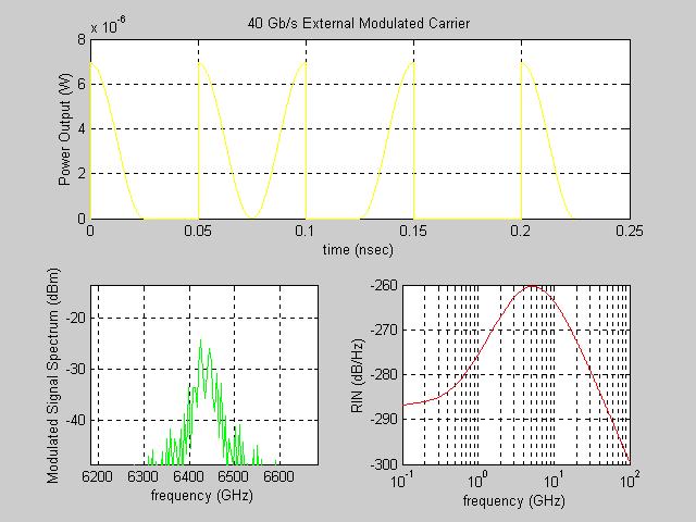
23 light modulates its phase but not its intensity. To modulate the intensity, Mach Zehender (MZ) modulator split its input light equally between a pair of parallel wave-guides. The modeled MZ modulator is a fabricated fiber with a ridge height of H=3.3µm, and electrode thickness of T = 10µm, because it gives an optimal performance with a bandwidth of 30GHz, a small conductor loss and fast interaction with the guided electromagnetic wave. The 180 or π phase shift voltage, V m (t) = V π, is 5V and insertion loss due to coupling losses at the input and output connector is 6dB. V π is the driving voltage, which achieves a π phase difference between the two light waves and results (theoretically) a complete cancellation of the carrier wave at the output port. Therefore V m,on = 0 and V m,off = V π and the power transfer or extinction ratio characteristics is modeled by the following relation ship as a function of the driving voltage.
24 Figure 8: Transfer characteristics of MZ modulator, P out πvm ( t) = Pin (cos 2. 2V π External modulation of novel optical line coded signal Novel optical line coded signal is modulated by the MZ modulator biases at its half power point, 3V π /2 as shown in Figure 9. The optical power spectrum of the modulated carrier is calculated as E( t) = Pout ( t) exp( j( ϖ ct + φ)) (13) Where P out (t) is the signal power, ω c is the optical carrier frequency φ is the phase shift produced by the modulator [9]. E(t) describes the optical field at the modulator output port and at the transmission fiber input. modulated signal 7.5V modulating signal time Figure 9: Transfer characteristics and biasing arrangement of novel optical line coding Modulated signal output of the MZ modulator and the power spectrum of the modulated signal are given in Figure 10.

25 Figure 10: Modulated signal ( ) output and the power spectrum Carrier suppressed duo-binary modulation As illustrated in the previous section, duo-binary coding uses a three level signal to reduce the required electrical and optical bandwidth. Reduced bandwidth increases the transmission distance because the effect of group velocity dispersion scales as f 2 L where f is the modulation frequency and L is the fiber length. The duo binary coded signal is modulated with a push pull type LiNbO 3 MZ modulator with a bandwidth of 30dB. Simple and efficient method is used to produce the double side band suppressed carrier duo binary modulated signal using a single off the shelf optical component [9]. The phase shift is applied to the MZ modulator in an anti symmetric fashion so that the induced side bands from the two branches add when the carrier component cancel. Suppressed carrier is achieved by biasing the MZ
26 modulator at V 0 = V π,, as shown in the Figure 11, such that the carrier components cancel at the output coupler of the modulator. modulated signal 5V modulating signal time Figure 11: Biasing the MZ modulator to generate duo binary optical signal Let assume the difference in phase between the two braches of the modulator is sinusoid added to the dc bias V 0 i.e. φ(t) = m cos(2πv c t) + φ 0 where v c is the frequency of the modulation tone, modulation index m is defined as πvm π m = and φ V = V 0 0 V where V m is the π π modulator driving voltage and V π is its half wave switching voltage. If the modulator is biased so that the electric field strength is linearly related to the input voltage (i.e. V 0 = V π and hence φ 0 = π) there will be no carrier component in the modulated signal. Finally the modulated signal will be, E sig ( t) = P sin[ mcos(2πv t)]cos(2πv t) (14) out m c
27 Hence the output of the MZ modulator will be a double side band suppressed carrier (DSB- SC) signal. [9]. Modulated duo binary waveform ant its power spectrum is shown in the Figure 12, and the carrier suppression is clearly indicated in the power spectrum. Figure 12: Modulated duo binary signal ( ) and its power spectrum> the centre of the spectrum is shifted to 1550 nm. Wavelength division multiplexing (WDM) operates by sending multiple light waves (frequencies) across a single optical fiber. Information is carried by each wavelength, which is called a channel, through either intensity (or amplitude) or phase modulation. At the receiving end, and optical demultiplexer is used to separate the frequencies, and the information carried by each channel is extracted separately. Binary digital signal, which is a full on/off intensity modulation, can also be carried by each individual channel, although the bit rate is expected to be lower than the intensity or phase modulation. As in conventional
28 frequency division multiplexing (FDM) carriers can be mixed onto a single medium because light at a given frequency doesn t interfere with light at another frequency with in the linier of approximation. The modulator encodes digital data into waveform symbols through either intensity or a phase modulation method, and the modulator reveres the process to obtain digital data. The switch nodes consist of add/drop multiplexes and demultiplexes, wavelength switches and wavelength converters. The multiplexers are used to combine the signal of different wavelengths for transmission. The demultiplexes are used to separate and filter different wavelength channels. The wavelength switch cross connects the input channels to the desired output channels. The function of the wavelength converters is to convert the over demand wavelengths to free wavelengths in a given fiber to achieve high channel utilization. The channel density is a key variable in WDM systems. The optics provides uniformly spaced slots for optical channels, although the system may not use all those slots. The spacing of the slots determines the density. The international telecommunication union grid has specified one set of standard center frequencies separated by 100GHz, which corresponds to about 0.8nm in the erbium fiber amplifier band. Some commercial systems have 50GHz grid spacing, ev ntually reaching 25GHz and even 12.5GHz. Typically spacing of 200GHz or less is called dense wavelength division multiplexing (DWDM). This allows many more channels to be multiplexed in the spectrum. Narrowing the spacing it is more difficult and more expensive to make multiplexing and de-multiplexing optics. On the other hand it will more utilize the expensive system bandwidth and more information (cannels) can be sent in the usable wavelength region.
29 In paper, 64 novel optical line coding modulated signals were multiplexed with 100GHz spacing (ranging from nm 1586nm) and 81 optical duo-binary coded signals were multiplexed with 50GHz spacing (ranging from nm nm) before transmitting them through the optical channel. Multiplexed signals are shown in Figure 13 and Figure 14. Figure 13: DWDM Multiplexed signals from MOCSS (64 channels of novel multi-level optical coding with 100 GHz spacing)
30 Figure 14: DWDM Multiplexed signals from MOCSS (81 channels of CS Duo-binary with 50 GHz spacing) The Mach Zehnder modulator, which is biased at 2.5 V, can be used to modulate novel optical coded signal and it should be biased at 5V for the carrier suppressed duo binary modulation. Due to the suppression of the unwanted carrier component in CS duo-binary (CS-DB) modulation, power spectrum of the modulated signal is less than 25 dbm. DWDM multiplexed power spectrums of both modulation techniques have been shown to be spectrally very efficient and well suited to be high capacity transmission. 4. COMPARISION OF THE PERFORMANCE OF DIFFERENT LINE CODING TECHNIQUES The intention of this section is to compare the performance of Novel optical line codes and optical duo-binary codes with conventional return to zero and non-return to zero line codes in dispersion compensated fiber optic links. In particularly carrier suppressed duo-binary and optical line coded signal transmission have been investigated in long haul 40 Gb/s per
31 channel WDM systems with paying strong attention to chromatic dispersion, nonlinear effects, attenuation, noise and spectral efficiency. 4.1 Dispersion tolerance comparison High-speed long distance WDM trunk lines over standard single mode fiber are necessarily dispersion compensated using dispersion compensating fiber (DCF). Therefore dispersion tolerance of each coding format in highly dispersive environment should be investigated. Our simulated experimental setup is shown in Figure 15. The DFB laser diode is used with wavelength 1550nm and the generated lightwaves are then modulated by a single or dual arm Mach Zehnder modulator operating in a push pull configuration. For RZ, NRZ modulation, electrical signals are applied to the modulator at 2.5 V (i.e. V bias = V π /2). In the case of carrier suppressed duo-binary, three level electrical signal is applied at maximum extinction, i.e. at V bias = V π, while in the case of novel optical line coding modulating signal is applied at V bias = 7.5V. The transmission line consists of single mode fiber with span loss α = db/km. The nonlinear coefficient γ is 2Km -1 W -1. Chromatic dispersion of the transmission line D is 17ps/nm/km with dispersion slope of dd/dλ = 0.08ps/nm 2 /km. Parameters of the single mode fiber used in this simulation is given in Table 1.
32 DFB 1550nm LiNbO3 Modulator SMF CODER To Receiver DATA Figure 15: Simulation setup with one wavelength channel SMF parameter Value Zero material dispersion 1270nm Zero total dispersion 1300nm Dispersion at 1550nm 17ps/nm/km Core radius 4.3µm Core index Fiber loss dB/km Table 3: Single mode fiber parameters Signal power spectrum and the modulated signal of each modulation scheme is given in Figure 16 and Figure 17.
33 (a) (b)
34 (c ) Figure 16: Modulated signal and the power spectrum of (a) RZ (b) duo- binary and (c) multilevel signals From the power spectrum of the signals it is clear that the reduction in the power spectral density less than 20dBm of the duo binary-coded signals is due to the suppression of the carrier signal. This reduction enables the system designers to use optical amplifiers immediately after modulation.
 multi-level optical coding (d) CS- duo binary modulation")
35 (a) (b) (c) (d) Figure 17: Back to back system eye diagrams for (a) RZ (b) NRZ (c) multi-level optical coding (d) CS- duo binary modulation techniques


36 Modulated signals were transmitted in step of 5km distance and the bit error rate was calculated. The Q-factor is plotted in the Figure 22.


37 Figure 18: Eye diagrams of RZ, NRZ, Novel optical coding and CS duo binary modulated signals after 5 Km of transmission


38 Figure 19: eye diagrams of RZ, NRZ, Novel optical coding and CS duo binary modulated signals after 10 Km of transmission


39 Figure 20: eye diagrams of RZ, NRZ, Novel optical coding and CS duo binary modulated signals after 15 Km of transmission
 Figure 22: Q-factor vs distance (without dispersion compensation) for RZ, NRZ, Novel optical coding and CS duo binary modulation 4.")
40 Figure 21:Eye diagrams of RZ, NRZ, Novel optical coding and CS duo binary modulated signals after 20 Km of transmission The Graph of Q factor Vs distance 8 Q factor 7 6 RZ NRZ Duoinary Novel Distance (Km) Figure 22: Q-factor vs distance (without dispersion compensation) for RZ, NRZ, Novel optical coding and CS duo binary modulation 4.2 Non linear tolerance measurement Light waves transmitted through a fiber have little interaction with each other, and are not changed by their passage through the fiber (except for absorption and scattering). However there are exceptions arising from the interactions between light waves and the material
41 transmitting them, which can affect optical signals. These processes generally are called nonlinear effects because their strength typically depends on the square of intensity. Therefore these effects will be significant when the power increased or when it is concentrated in a small area, such as the core of an optical fiber. Brillouin scattering, self phase modulation and the cross phase modulation are the more significant non linear effects that should be consider in optical transmission systems. Brillouin scattering occurs when signal power reaches a level significant to generate tiny acoustic vibrations in the glass. This can occur at powers as low as a few mw in single mode fiber. It can occur when only a single channel is transmitted. Variation of the refractive index with the light passing through it causes intensity modulation of an optical channel to modulate the phase of the optical channel that creates it, and the effect is called self phase modulation. This effect also can occur in single channel systems. Systems carrying multiple channels are vulnerable to cross phase modulation. Variation in the intensity of one optical channel cause changes in the refractive index affecting other optical channels. These changes modulate the phase of light on other optical channels. When the channel spacing is less than 80GHz system limitations are caused only by single channel limitations and there are no further impairments due to multi-channel effects. At the channel spacing less than 80GHz multi-channel effects occur.
42 DFB DFB external modulator DSF zero dispersion at 1550nm Eye diagram DFB DFB Coder (novel optical line coding/ duobinary coding Data Figure 23: Simulation setup with ten channels and DSF To evaluate the nonlinear tolerance of different line coding techniques, modulated signals were transmitted through dispersion-shifted fiber (DSF) with zero dispersion at 1550nm for 50km. Since the dispersion is zero, resultant distortion is mainly due to the nonlinear effects. Parameters of the DSF is given in the Table 2 Parameter Description Fiber core material Type E (Quenched SiO 2 ) Dispersion at 1550nm Zero Core index Delta value % Diameter µm Table 4 Parameters of dispersion shifted fiber (DSF) To investigate the effect of Brillouin scattering and self phase modulation single channel was transmitted along the DSF and amplified to different power levels. And the resultant eye diagrams after 50km are given in Figure 24 to Figure 26
43 To investigate the effect of cross phase modulation ten channels were multiplexed using WDM technology with 50GHz spacing, and transmitted along the DSF and injected 100dBm power. The resultant eye diagrams after 50km is given in Figure 27 to Figure 28.

44 Figure 24: Eye diagrams at 50 Km for RZ, NRZ, CS duo binary and Novel optical coding


45 Figure 25: Eye diagrams at 50 Km after injecting 10dBm power for RZ, NRZ, CS duo binary and multi-level coding

46 Figure 26: Eye diagrams at 50Km after injecting 15dBm power for RZ, NRZ, CS duo binary and multi-level optical coding


47 Figure 27: Eye diagrams at 50 Km after injecting 20dBm power for RZ, NRZ, CS duo binary and multilevel optical coding


48 Figure 28: Eye diagrams at 50 Km for 10 channels of CS duo binary and multi-level optical coding. Figure 29 Eye diagrams at 50Km after injecting 20 dbm for 10 channels of CS duo binary and multi-level optical coding
49 100GHz spaced 40Gbit/s x 65 WDM transmission over 100km dispersion managed fiber using Novel optical line code (order one) The block diagram in Figure 30 shown below demonstrates 2.60Tbit/s WDM transmission using 65 channel multiplexed 40Gbit/s novel optical line coded signals over a 70 Km single mode fiber (SMF) and 30 Km of dispersion compensation fiber (DCF). Transmitted 46 channels are from nm (195.30THz) to nm(189.00THz) with 100GHz channel spacing. DFB DFB external modulator 70 Km SMF 30 km DCF DFB DFB Coder (novel optical line coding) To Receiver / Regenerator Data Figure 30: Block diagram of the system The zero dispersion wavelength of the 70km-transmission SMF is 1300nm and its dispersion at 1550nm is 17ps/nm/km. Dispersion is compensated with a 30km dispersion compensated fiber, which has a dispersion of 40ps/nm/km at 1550nm. Power spectrum of the WDM multiplexed carriers is given in Figure Figure 31.

50 Figure 31: Multiplexed power spectrum of modulated carriers Single clad fibber with material type E is used to design the DCF with core index, % delta and µm diameter. The total dispersion is 40ps/nm/km at 1550nm. The characteristics of the designed DCF are shown in Figure 32. Figure 32: Total dispersion of the DCF

51 Figure 33 Eye diagram after 100Km transmission (with dispersion compensation) Eye diagram after transmitting the multiplexed signal for 100Km along the SMF and DCF is shown Figure GHz spacing 40Gbit/s x 81 DWDM transmission over 100km dispersion managed fiber using carrier suppressed optical duo-binary Coding The block diagram in Figure 34 shown below demonstrates 3.24Tbit/s WDM transmission using 81 channel multiplexed 40Gbit/s duobinary coded signals over a 70 Km single mode fiber (SMF) and 30 Km of dispersion compensation fiber (DCF). Transmitted 81 channels are from nm(195.30THz) to nm(191.25THz) with 50GHz channel spacing.
 To Receiver / Regenerator Data Figure 34: Block diagram of the system The zero dispersion wavelength of the 70km-transmission SMF is 1300nm and its dispersion at 1550nm is")
52 DFB DFB external modulator 70 Km SMF 30 km DCF DFB DFB Coder (duo binary codr) To Receiver / Regenerator Data Figure 34: Block diagram of the system The zero dispersion wavelength of the 70km-transmission SMF is 1300nm and its dispersion at 1550nm is 17ps/nm/km. Dispersion is compensated with a 30km dispersion compensated fiber, which has a dispersion of 40ps/nm/km at 1550nm. Power spectrum of the WDM multiplexed carriers are given in Figure 35. Figure 35: Multiplexed power spectrum of modulated carriers Single clad fiber with material type E is used to design the DCF with core index, % delta and µm diameter. The total dispersion is 40ps/nm/km at 1550nm. The characteristic of the designed DCF is shown Figure 36.
 From the eye diagram of figure 30, it can be observed that there is a high frequency noise associate with the upper level")
53 Figure 36: Total dispersion of the DCF Eye diagram after transmitting the multiplexed signal for 100Km along the SMF and DCF is shown below. Figure 37 Eye diagram after 100Km transmission (with dispersion compensation) From the eye diagram of figure 30, it can be observed that there is a high frequency noise associate with the upper level of the eye diagram. Performance of the novel optical modulation format can be develop further by eliminating this noise by using a transmit filter
54 between encoder and the modulator. Ideal low pass filter is one of the best filters, immediately followed by a sixth order Butterworth type. At the presence of high dispersion this filter should have a sharp cutoff frequency [5]. 5. CONCLUSIONS This paper presents the implementation of the novel optical line coding technique (multilevel signaling) and carrier suppressed duo-binary-coding technique, in 40Gbit/s per channel long haul optical communication networks. Dispersion tolerance and the non linear tolerance measurement of those modulation formats were investigated, with number of case studies and comparing the simulation results with the performance of conventional RZ and NRZ modulation format in similar conditions. Finally the capability of using the interested modulation formats in DWDM multiplexed multi channel optical communication networks along the dispersion managed fiber optical links with 100Km amplifier/regenerator spacing is illustrated. From the simulation results indicate very clearly that dispersion tolerance of novel optical coding and optical duo-binary coding is superior to the conventional modulation techniques along the single mode fiber (without dispersion compensation). Initially (when the distance is less than about 11Km) duo-binary provide the best dispersion tolerance, but when the length increase further, novel optical coded signal becomes less dispersive. When considering the non-linear tolerance, interested modulation techniques provided better results compared to the RZ and NRZ modulations. Up to the point where injected power is 15dBm both CS duo-binary and novel optical coding perform equally well, however when the injected power is 20dBm first is better than the latter. This is mainly due to the low power
SHF Communication Technologies AG
 SHF Communication Technologies AG Wilhelm-von-Siemens-Str. 23 Aufgang D 12277 Berlin Marienfelde Germany Phone ++49 30 / 772 05 10 Fax ++49 30 / 753 10 78 E-Mail: sales@shf.biz Web: http://www.shf.biz
Analysis of Self Phase Modulation Fiber nonlinearity in Optical Transmission System with Dispersion
 36 Analysis of Self Phase Modulation Fiber nonlinearity in Optical Transmission System with Dispersion Supreet Singh 1, Kulwinder Singh 2 1 Department of Electronics and Communication Engineering, Punjabi
FWM Suppression in WDM Systems Using Advanced Modulation Formats
 FWM Suppression in WDM Systems Using Advanced Modulation Formats M.M. Ibrahim (eng.mohamed.ibrahim@gmail.com) and Moustafa H. Aly (drmosaly@gmail.com) OSA Member Arab Academy for Science, Technology and
Performance Limitations of WDM Optical Transmission System Due to Cross-Phase Modulation in Presence of Chromatic Dispersion
 Performance Limitations of WDM Optical Transmission System Due to Cross-Phase Modulation in Presence of Chromatic Dispersion M. A. Khayer Azad and M. S. Islam Institute of Information and Communication
Department of Electrical and Computer Systems Engineering
 Department of Electrical and Computer Systems Engineering Technical Report MECSE-23-2003 Double-Sideband Carrier Suppressed RZ and NRZ Modulation Formats for Ultra-high Capacity 40 Gb/s DWDM Optical Communications
Performance Evaluation of 32 Channel DWDM System Using Dispersion Compensation Unit at Different Bit Rates
 Performance Evaluation of 32 Channel DWDM System Using Dispersion Compensation Unit at Different Bit Rates Simarpreet Kaur Gill 1, Gurinder Kaur 2 1Mtech Student, ECE Department, Rayat- Bahra University,
40Gb/s Optical Transmission System Testbed
 The University of Kansas Technical Report 40Gb/s Optical Transmission System Testbed Ron Hui, Sen Zhang, Ashvini Ganesh, Chris Allen and Ken Demarest ITTC-FY2004-TR-22738-01 January 2004 Sponsor: Sprint
CHAPTER 4 RESULTS. 4.1 Introduction
 CHAPTER 4 RESULTS 4.1 Introduction In this chapter focus are given more on WDM system. The results which are obtained mainly from the simulation work are presented. In simulation analysis, the study will
Performance Analysis Of Hybrid Optical OFDM System With High Order Dispersion Compensation
 Performance Analysis Of Hybrid Optical OFDM System With High Order Dispersion Compensation Manpreet Singh Student, University College of Engineering, Punjabi University, Patiala, India. Abstract Orthogonal
Optical Complex Spectrum Analyzer (OCSA)
") Optical Complex Spectrum Analyzer (OCSA) First version 24/11/2005 Last Update 05/06/2013 Distribution in the UK & Ireland Characterisation, Measurement & Analysis Lambda Photometrics Limited Lambda House
Optical Complex Spectrum Analyzer (OCSA) First version 24/11/2005 Last Update 05/06/2013 Distribution in the UK & Ireland Characterisation, Measurement & Analysis Lambda Photometrics Limited Lambda House
π code 0 Changchun,130000,China Key Laboratory of National Defense.Changchun,130000,China Keywords:DPSK; CSRZ; atmospheric channel
 4th International Conference on Computer, Mechatronics, Control and Electronic Engineering (ICCMCEE 2015) Differential phase shift keying in the research on the effects of type pattern of space optical
Phase Modulator for Higher Order Dispersion Compensation in Optical OFDM System
 Phase Modulator for Higher Order Dispersion Compensation in Optical OFDM System Manpreet Singh 1, Karamjit Kaur 2 Student, University College of Engineering, Punjabi University, Patiala, India 1. Assistant
Optical Transport Tutorial
 Optical Transport Tutorial 4 February 2015 2015 OpticalCloudInfra Proprietary 1 Content Optical Transport Basics Assessment of Optical Communication Quality Bit Error Rate and Q Factor Wavelength Division
Department of Electrical and Computer Systems Engineering
 Department of Electrical and Computer Systems Engineering Technical Report MECSE-4-2005 DWDM Optically Amplified Transmission Systems - SIMULINK Models and Test-Bed: Part III DPSK L.N. Binh and Y.L.Cheung
OPTICAL NETWORKS. Building Blocks. A. Gençata İTÜ, Dept. Computer Engineering 2005
 OPTICAL NETWORKS Building Blocks A. Gençata İTÜ, Dept. Computer Engineering 2005 Introduction An introduction to WDM devices. optical fiber optical couplers optical receivers optical filters optical amplifiers
Next-Generation Optical Fiber Network Communication
 Next-Generation Optical Fiber Network Communication Naveen Panwar; Pankaj Kumar & manupanwar46@gmail.com & chandra.pankaj30@gmail.com ABSTRACT: In all over the world, much higher order off modulation formats
Available online at ScienceDirect. Procedia Computer Science 93 (2016 )
") Available online at www.sciencedirect.com ScienceDirect Procedia Computer Science 93 (016 ) 647 654 6th International Conference On Advances In Computing & Communications, ICACC 016, 6-8 September 016,
Available online at www.sciencedirect.com ScienceDirect Procedia Computer Science 93 (016 ) 647 654 6th International Conference On Advances In Computing & Communications, ICACC 016, 6-8 September 016,
Implementing of High Capacity Tbps DWDM System Optical Network
 , pp. 211-218 http://dx.doi.org/10.14257/ijfgcn.2016.9.6.20 Implementing of High Capacity Tbps DWDM System Optical Network Daleep Singh Sekhon *, Harmandar Kaur Deptt.of ECE, GNDU Regional Campus, Jalandhar,Punjab,India
Performance of A Multicast DWDM Network Applied to the Yemen Universities Network using Quality Check Algorithm
 Performance of A Multicast DWDM Network Applied to the Yemen Universities Network using Quality Check Algorithm Khaled O. Basulaim, Samah Ali Al-Azani Dept. of Information Technology Faculty of Engineering,
Department of Electrical and Computer Systems Engineering
 Department of Electrical and Computer Systems Engineering Technical Report MECSE-4-006 40Gb/s Amplitude and Phase Modulation Optical Fibre Transmission Systems L.N. Binh, H.S. Tiong and T.L. Huynh 40Gb/s
UNIVERSITY OF TORONTO FACULTY OF APPLIED SCIENCE AND ENGINEERING. FINAL EXAMINATION, April 2017 DURATION: 2.5 hours
 UNIVERSITY OF TORONTO FACULTY OF APPLIED SCIENCE AND ENGINEERING ECE4691-111 S - FINAL EXAMINATION, April 2017 DURATION: 2.5 hours Optical Communication and Networks Calculator Type: 2 Exam Type: X Examiner:
Design of Ultra High Capacity DWDM System with Different Modulation Formats
 Design of Ultra High Capacity DWDM System with Different Modulation Formats A. Nandhini 1, K. Gokulakrishnan 2 1 PG Scholar, Department of Electronics & Communication Engineering, Regional Center, Anna
Department of Electrical and Computer Systems Engineering
 Department of Electrical and Computer Systems Engineering Technical Report MECSE-2-2005 MOCSS2004: Monash Optical Communication System Simulator for Optically Amplified DWDM Advanced Modulation Formats
Performance Analysis of Gb/s DWDM Metropolitan Area Network using SMF-28 and MetroCor Optical Fibres
 Research Cell: An International Journal of Engineering Sciences ISSN: 2229-6913 Issue Sept 2011, Vol. 4 11 Performance Analysis of 32 2.5 Gb/s DWDM Metropolitan Area Network using SMF-28 and MetroCor Optical
Eye-Diagram-Based Evaluation of RZ and NRZ Modulation Methods in a 10-Gb/s Single-Channel and a 160-Gb/s WDM Optical Networks
 International Journal of Optics and Applications 2017, 7(2): 31-36 DOI: 10.5923/j.optics.20170702.01 Eye-Diagram-Based Evaluation of RZ and NRZ Modulation Methods in a 10-Gb/s Single-Channel and a 160-Gb/s
Photonics and Optical Communication Spring 2005
 Photonics and Optical Communication Spring 2005 Final Exam Instructor: Dr. Dietmar Knipp, Assistant Professor of Electrical Engineering Name: Mat. -Nr.: Guidelines: Duration of the Final Exam: 2 hour You
Department of Electrical and Computer Systems Engineering
 Department of Electrical and Computer Systems Engineering Technical Report MECSE-5-2005 SIMULINK Models for Advanced Optical Communications: Part IV- DQPSK Modulation Format L.N. Binh and B. Laville SIMULINK
Comparison between DWDM Transmission Systems over SMF and NZDSF with 25 40Gb/s signals and 50GHz Channel Spacing
 Comparison between DWDM Transmission Systems over SMF and NZDSF with 25 4Gb/s signals and 5GHz Channel Spacing Ruben Luís, Daniel Fonseca, Adolfo V. T. Cartaxo Abstract The use of new types of fibre with
CHAPTER 5 SPECTRAL EFFICIENCY IN DWDM
 61 CHAPTER 5 SPECTRAL EFFICIENCY IN DWDM 5.1 SPECTRAL EFFICIENCY IN DWDM Due to the ever-expanding Internet data traffic, telecommunication networks are witnessing a demand for high-speed data transfer.
Lecture 2 Fiber Optical Communication Lecture 2, Slide 1
 Lecture 2 General concepts Digital modulation in general Optical modulation Direct modulation External modulation Modulation formats Differential detection Coherent detection Fiber Optical Communication
Power penalty caused by Stimulated Raman Scattering in WDM Systems
 Paper Power penalty caused by Stimulated Raman Scattering in WDM Systems Sławomir Pietrzyk, Waldemar Szczęsny, and Marian Marciniak Abstract In this paper we present results of an investigation into the
High Performance Dispersion and Dispersion Slope Compensating Fiber Modules for Non-zero Dispersion Shifted Fibers
 High Performance Dispersion and Dispersion Slope Compensating Fiber Modules for Non-zero Dispersion Shifted Fibers Kazuhiko Aikawa, Ryuji Suzuki, Shogo Shimizu, Kazunari Suzuki, Masato Kenmotsu, Masakazu
Advanced Test Equipment Rentals ATEC (2832)
") Established 1981 Advanced Test Equipment Rentals www.atecorp.com 800-404-ATEC (2832) BN 8000 May 2000 Profile Optische Systeme GmbH Gauss Str. 11 D - 85757 Karlsfeld / Germany Tel + 49 8131 5956-0 Fax
Established 1981 Advanced Test Equipment Rentals www.atecorp.com 800-404-ATEC (2832) BN 8000 May 2000 Profile Optische Systeme GmbH Gauss Str. 11 D - 85757 Karlsfeld / Germany Tel + 49 8131 5956-0 Fax
UNIT - 7 WDM CONCEPTS AND COMPONENTS
 UNIT - 7 LECTURE-1 WDM CONCEPTS AND COMPONENTS WDM concepts, overview of WDM operation principles, WDM standards, Mach-Zehender interferometer, multiplexer, Isolators and circulators, direct thin film
Analyzing the Non-Linear Effects in DWDM Optical Network Using MDRZ Modulation Format
 Analyzing the Non-Linear Effects in DWDM Optical Network Using MDRZ Modulation Format Ami R. Lavingia Electronics & Communication Dept. SAL Institute of Technology & Engineering Research Gujarat Technological
Lecture 6 Fiber Optical Communication Lecture 6, Slide 1
 Lecture 6 Optical transmitters Photon processes in light matter interaction Lasers Lasing conditions The rate equations CW operation Modulation response Noise Light emitting diodes (LED) Power Modulation
Lecture 8 Fiber Optical Communication Lecture 8, Slide 1
 Lecture 8 Bit error rate The Q value Receiver sensitivity Sensitivity degradation Extinction ratio RIN Timing jitter Chirp Forward error correction Fiber Optical Communication Lecture 8, Slide Bit error
EXAMINATION FOR THE DEGREE OF B.E. and M.E. Semester
 EXAMINATION FOR THE DEGREE OF B.E. and M.E. Semester 2 2009 101908 OPTICAL COMMUNICATION ENGINEERING (Elec Eng 4041) 105302 SPECIAL STUDIES IN MARINE ENGINEERING (Elec Eng 7072) Official Reading Time:
A Technique to improve the Spectral efficiency by Phase shift keying modulation technique at 40 Gb/s in DWDM optical systems.
 A Technique to improve the Spectral efficiency by Phase shift keying modulation technique at 40 Gb/s in DWDM optical systems. A.V Ramprasad and M.Meenakshi Reserach scholar and Assistant professor, Department
Fiber-Optic Communication Systems
 Fiber-Optic Communication Systems Second Edition GOVIND P. AGRAWAL The Institute of Optics University of Rochester Rochester, NY A WILEY-iNTERSCIENCE PUBLICATION JOHN WILEY & SONS, INC. NEW YORK / CHICHESTER
Optical Amplifiers Photonics and Integrated Optics (ELEC-E3240) Zhipei Sun Photonics Group Department of Micro- and Nanosciences Aalto University
 Zhipei Sun Photonics Group Department of Micro- and Nanosciences Aalto University") Photonics Group Department of Micro- and Nanosciences Aalto University Optical Amplifiers Photonics and Integrated Optics (ELEC-E3240) Zhipei Sun Last Lecture Topics Course introduction Ray optics & optical
Photonics Group Department of Micro- and Nanosciences Aalto University Optical Amplifiers Photonics and Integrated Optics (ELEC-E3240) Zhipei Sun Last Lecture Topics Course introduction Ray optics & optical
Dr. Monir Hossen ECE, KUET
 Dr. Monir Hossen ECE, KUET 1 Outlines of the Class Principles of WDM DWDM, CWDM, Bidirectional WDM Components of WDM AWG, filter Problems with WDM Four-wave mixing Stimulated Brillouin scattering WDM Network
Module 16 : Integrated Optics I
 Module 16 : Integrated Optics I Lecture : Integrated Optics I Objectives In this lecture you will learn the following Introduction Electro-Optic Effect Optical Phase Modulator Optical Amplitude Modulator
The Reduction of FWM effects using Duobinary Modulation in a Two-Channel D-WDM System
 The Reduction of FWM effects using Duobinary Modulation in a Two-Channel D-WDM System Laxman Tawade 1, Balasaheb Deokate 2 Department of Electronic and Telecommunication Vidya Pratishthan s College of
Optical Communications and Networks - Review and Evolution (OPTI 500) Massoud Karbassian
 Massoud Karbassian") Optical Communications and Networks - Review and Evolution (OPTI 500) Massoud Karbassian m.karbassian@arizona.edu Contents Optical Communications: Review Optical Communications and Photonics Why Photonics?
Optical Communications and Networks - Review and Evolution (OPTI 500) Massoud Karbassian m.karbassian@arizona.edu Contents Optical Communications: Review Optical Communications and Photonics Why Photonics?
Mixing TrueWave RS Fiber with Other Single-Mode Fiber Designs Within a Network
 Mixing TrueWave RS Fiber with Other Single-Mode Fiber Designs Within a Network INTRODUCTION A variety of single-mode fiber types can be found in today s installed networks. Standards bodies, such as the
SIMULATIVE INVESTIGATION OF SINGLE-TONE ROF SYSTEM USING VARIOUS DUOBINARY MODULATION FORMATS
 SIMULATIVE INVESTIGATION OF SINGLE-TONE ROF SYSTEM USING VARIOUS DUOBINARY MODULATION FORMATS Namita Kathpal 1 and Amit Kumar Garg 2 1,2 Department of Electronics & Communication Engineering, Deenbandhu
Chapter 10 WDM concepts and components
 Chapter 10 WDM concepts and components - Outline 10.1 Operational principle of WDM 10. Passive Components - The x Fiber Coupler - Scattering Matrix Representation - The x Waveguide Coupler - Mach-Zehnder
Lecture 7 Fiber Optical Communication Lecture 7, Slide 1
 Dispersion management Lecture 7 Dispersion compensating fibers (DCF) Fiber Bragg gratings (FBG) Dispersion-equalizing filters Optical phase conjugation (OPC) Electronic dispersion compensation (EDC) Fiber
UNIT - 7 WDM CONCEPTS AND COMPONENTS
 UNIT - 7 WDM CONCEPTS AND COMPONENTS WDM concepts, overview of WDM operation principles, WDM standards, Mach-Zehender interferometer, multiplexer, Isolators and circulators, direct thin film filters, active
ARTICLE IN PRESS. Optik 119 (2008)
") Optik 119 (28) 39 314 Optik Optics www.elsevier.de/ijleo Timing jitter dependence on data format for ideal dispersion compensated 1 Gbps optical communication systems Manjit Singh a, Ajay K. Sharma b,,
Optik 119 (28) 39 314 Optik Optics www.elsevier.de/ijleo Timing jitter dependence on data format for ideal dispersion compensated 1 Gbps optical communication systems Manjit Singh a, Ajay K. Sharma b,,
11.1 Gbit/s Pluggable Small Form Factor DWDM Optical Transceiver Module
 INFORMATION & COMMUNICATIONS 11.1 Gbit/s Pluggable Small Form Factor DWDM Transceiver Module Yoji SHIMADA*, Shingo INOUE, Shimako ANZAI, Hiroshi KAWAMURA, Shogo AMARI and Kenji OTOBE We have developed
RZ BASED DISPERSION COMPENSATION TECHNIQUE IN DWDM SYSTEM FOR BROADBAND SPECTRUM
 RZ BASED DISPERSION COMPENSATION TECHNIQUE IN DWDM SYSTEM FOR BROADBAND SPECTRUM Prof. Muthumani 1, Mr. Ayyanar 2 1 Professor and HOD, 2 UG Student, Department of Electronics and Communication Engineering,
Optical Digital Transmission Systems. Xavier Fernando ADROIT Lab Ryerson University
 Optical Digital Transmission Systems Xavier Fernando ADROIT Lab Ryerson University Overview In this section we cover point-to-point digital transmission link design issues (Ch8): Link power budget calculations
Elements of Optical Networking
 Bruckner Elements of Optical Networking Basics and practice of optical data communication With 217 Figures, 13 Tables and 93 Exercises Translated by Patricia Joliet VIEWEG+ TEUBNER VII Content Preface
S Optical Networks Course Lecture 4: Transmission System Engineering
 S-72.3340 Optical Networks Course Lecture 4: Transmission System Engineering Edward Mutafungwa Communications Laboratory, Helsinki University of Technology, P. O. Box 2300, FIN-02015 TKK, Finland Tel:
Simulative Analysis of 40 Gbps DWDM System Using Combination of Hybrid Modulators and Optical Filters for Suppression of Four-Wave Mixing
 Vol.9, No.7 (2016), pp.213-220 http://dx.doi.org/10.14257/ijsip.2016.9.7.18 Simulative Analysis of 40 Gbps DWDM System Using Combination of Hybrid Modulators and Optical Filters for Suppression of Four-Wave
Lecture 9 External Modulators and Detectors
 Optical Fibres and Telecommunications Lecture 9 External Modulators and Detectors Introduction Where are we? A look at some real laser diodes. External modulators Mach-Zender Electro-absorption modulators
Modulation of light. Direct modulation of sources Electro-absorption (EA) modulators
 modulators") Modulation of light Direct modulation of sources Electro-absorption (EA) modulators Why Modulation A communication link is established by transmission of information reliably Optical modulation is embedding
Modulation of light Direct modulation of sources Electro-absorption (EA) modulators Why Modulation A communication link is established by transmission of information reliably Optical modulation is embedding
SUBMARINE SYSTEM UPGRADES WITH 25 GHZ CHANNEL SPACING USING DRZ AND RZ-DPSK MODULATION FORMATS
 SUBMARINE SYSTEM UPGRADES WITH 25 GHZ CHANNEL SPACING USING DRZ AND RZ-DPSK MODULATION FORMATS Jiping Wen, Chunmei Yu, Tiegang Zhou, Xiaoyan Fan, Liping Ma (Huawei Marine Networks Co Ltd) Email:
Chirped Bragg Grating Dispersion Compensation in Dense Wavelength Division Multiplexing Optical Long-Haul Networks
 363 Chirped Bragg Grating Dispersion Compensation in Dense Wavelength Division Multiplexing Optical Long-Haul Networks CHAOUI Fahd 3, HAJAJI Anas 1, AGHZOUT Otman 2,4, CHAKKOUR Mounia 3, EL YAKHLOUFI Mounir
RADIO-OVER-FIBER TRANSPORT SYSTEMS BASED ON DFB LD WITH MAIN AND 1 SIDE MODES INJECTION-LOCKED TECHNIQUE
 Progress In Electromagnetics Research Letters, Vol. 7, 25 33, 2009 RADIO-OVER-FIBER TRANSPORT SYSTEMS BASED ON DFB LD WITH MAIN AND 1 SIDE MODES INJECTION-LOCKED TECHNIQUE H.-H. Lu, C.-Y. Li, C.-H. Lee,
Analogical chromatic dispersion compensation
 Chapter 2 Analogical chromatic dispersion compensation 2.1. Introduction In the last chapter the most important techniques to compensate chromatic dispersion have been shown. Optical techniques are able
Chapter 8. Digital Links
 Chapter 8 Digital Links Point-to-point Links Link Power Budget Rise-time Budget Power Penalties Dispersions Noise Content Photonic Digital Link Analysis & Design Point-to-Point Link Requirement: - Data
REDUCTION OF CROSSTALK IN WAVELENGTH DIVISION MULTIPLEXED FIBER OPTIC COMMUNICATION SYSTEMS
 Progress In Electromagnetics Research, PIER 77, 367 378, 2007 REDUCTION OF CROSSTALK IN WAVELENGTH DIVISION MULTIPLEXED FIBER OPTIC COMMUNICATION SYSTEMS R. Tripathi Northern India Engineering College
Chromatic Dispersion Compensation in Optical Fiber Communication System and its Simulation
 Indian Journal of Science and Technology Supplementary Article Chromatic Dispersion Compensation in Optical Fiber Communication System and its Simulation R. Udayakumar 1 *, V. Khanaa 2 and T. Saravanan
Photoneco white papers: Single-modulator RZ-DQPSK transmitter Description of the prior art
 Photoneco white papers: Single-modulator RZ-DQPSK transmitter Description of the prior art Optical fiber systems in their infancy used to waste bandwidth both in the optical and in the electrical domain
ANALYSIS OF FWM POWER AND EFFICIENCY IN DWDM SYSTEMS BASED ON CHROMATIC DISPERSION AND CHANNEL SPACING
 ANALYSIS OF FWM POWER AND EFFICIENCY IN DWDM SYSTEMS BASED ON CHROMATIC DISPERSION AND CHANNEL SPACING S Sugumaran 1, Manu Agarwal 2, P Arulmozhivarman 3 School of Electronics Engineering, VIT University,
Photonics (OPTI 510R 2017) - Final exam. (May 8, 10:30am-12:30pm, R307)
 - Final exam. (May 8, 10:30am-12:30pm, R307)") Photonics (OPTI 510R 2017) - Final exam (May 8, 10:30am-12:30pm, R307) Problem 1: (30pts) You are tasked with building a high speed fiber communication link between San Francisco and Tokyo (Japan) which
Photonics (OPTI 510R 2017) - Final exam (May 8, 10:30am-12:30pm, R307) Problem 1: (30pts) You are tasked with building a high speed fiber communication link between San Francisco and Tokyo (Japan) which
A NOVEL SCHEME FOR OPTICAL MILLIMETER WAVE GENERATION USING MZM
 A NOVEL SCHEME FOR OPTICAL MILLIMETER WAVE GENERATION USING MZM Poomari S. and Arvind Chakrapani Department of Electronics and Communication Engineering, Karpagam College of Engineering, Coimbatore, Tamil
Optical Fiber Technology. Photonic Network By Dr. M H Zaidi
 Optical Fiber Technology Numerical Aperture (NA) What is numerical aperture (NA)? Numerical aperture is the measure of the light gathering ability of optical fiber The higher the NA, the larger the core
Department of Electrical and Computer Systems Engineering
 Department of Electrical and Computer Systems Engineering Technical Report MECSE-3-2005 DWDM Advanced Optical Communication Simulink Models: Part I Optical Spectra L.N Binh and Y.L. Cheung DWDM ADVANCED
Performance Analysis of Optical Time Division Multiplexing Using RZ Pulse Generator
 Available Online at www.ijcsmc.com International Journal of Computer Science and Mobile Computing A Monthly Journal of Computer Science and Information Technology IJCSMC, Vol. 4, Issue. 10, October 2015,
PERFORMANCE ENHANCEMENT OF 32 CHANNEL LONG HAUL DWDM SOLITON LINK USING ELECTRONIC DISPERSION COMPENSATION
 International Journal of Electronics, Communication & Instrumentation Engineering Research and Development (IJECIERD) ISSN 2249-684X Vol. 2 Issue 4 Dec - 2012 11-16 TJPRC Pvt. Ltd., PERFORMANCE ENHANCEMENT
All-Optical Signal Processing and Optical Regeneration
 1/36 All-Optical Signal Processing and Optical Regeneration Govind P. Agrawal Institute of Optics University of Rochester Rochester, NY 14627 c 2007 G. P. Agrawal Outline Introduction Major Nonlinear Effects
Performance Analysis of Dwdm System With Different Modulation Techique And Photodiode
 The International Journal Of Engineering And Science (IJES) Volume 2 Issue 7 Pages 07-11 2013 ISSN(e): 2319 1813 ISSN(p): 2319 1805 Performance Analysis of Dwdm System With Different Modulation Techique
Implementation and analysis of 2 Tbps MDRZ DWDM system at ultra narrow channel spacing
 Implementation and analysis of 2 Tbps MDRZ DWDM system at ultra narrow channel spacing 1 Ragini Sharma, 2 Kamaldeep Kaur 1 Student, 2 Assistant Professor Department of Electrical Engineering BBSBEC, Fatehgarh
Study of Multiwavelength Fiber Laser in a Highly Nonlinear Fiber
 Study of Multiwavelength Fiber Laser in a Highly Nonlinear Fiber I. H. M. Nadzar 1 and N. A.Awang 1* 1 Faculty of Science, Technology and Human Development, Universiti Tun Hussein Onn Malaysia, Johor,
Spectrally Compact Optical Subcarrier Multiplexing with 42.6 Gbit/s AM-PSK Payload and 2.5Gbit/s NRZ Labels
 Spectrally Compact Optical Subcarrier Multiplexing with 42.6 Gbit/s AM-PSK Payload and 2.5Gbit/s NRZ Labels A.K. Mishra (1), A.D. Ellis (1), D. Cotter (1),F. Smyth (2), E. Connolly (2), L.P. Barry (2)
Compensation of Dispersion in 10 Gbps WDM System by Using Fiber Bragg Grating
 International Journal of Computational Engineering & Management, Vol. 15 Issue 5, September 2012 www..org 16 Compensation of Dispersion in 10 Gbps WDM System by Using Fiber Bragg Grating P. K. Raghav 1,
CHAPTER 3 PERFORMANCE OF MODULATION FORMATS ON DWDM OPTICAL SYSTEMS
 67 CHAPTER 3 PERFORMANCE OF MODULATION FORMATS ON DWDM OPTICAL SYSTEMS 3.1 INTRODUCTION The need for higher transmission rate in Dense Wavelength Division optical systems necessitates the selection of
Fiber Optic Communication Link Design
 Fiber Optic Communication Link Design By Michael J. Fujita, S.K. Ramesh, PhD, Russell L. Tatro Abstract The fundamental building blocks of an optical fiber transmission link are the optical source, the
Spectral Response of FWM in EDFA for Long-haul Optical Communication
 Spectral Response of FWM in EDFA for Long-haul Optical Communication Lekshmi.S.R 1, Sindhu.N 2 1 P.G.Scholar, Govt. Engineering College, Wayanad, Kerala, India 2 Assistant Professor, Govt. Engineering
is a method of transmitting information from one place to another by sending light through an optical fiber. The light forms an electromagnetic
 is a method of transmitting information from one place to another by sending light through an optical fiber. The light forms an electromagnetic carrier wave that is modulated to carry information. The
8 10 Gbps optical system with DCF and EDFA for different channel spacing
 Research Article International Journal of Advanced Computer Research, Vol 6(24) ISSN (Print): 2249-7277 ISSN (Online): 2277-7970 http://dx.doi.org/10.19101/ijacr.2016.624002 8 10 Gbps optical system with
OFC SYSTEMS Performance & Simulations. BC Choudhary NITTTR, Sector 26, Chandigarh
 OFC SYSTEMS Performance & Simulations BC Choudhary NITTTR, Sector 26, Chandigarh High Capacity DWDM OFC Link Capacity of carrying enormous rates of information in THz 1.1 Tb/s over 150 km ; 55 wavelengths
Performance Analysis of Designing a Hybrid Optical Amplifier (HOA) for 32 DWDM Channels in L-band by using EDFA and Raman Amplifier
 for 32 DWDM Channels in L-band by using EDFA and Raman Amplifier") Performance Analysis of Designing a Hybrid Optical Amplifier (HOA) for 32 DWDM Channels in L-band by using EDFA and Raman Amplifier Aied K. Mohammed, PhD Department of Electrical Engineering, University
Performance Analysis of Designing a Hybrid Optical Amplifier (HOA) for 32 DWDM Channels in L-band by using EDFA and Raman Amplifier Aied K. Mohammed, PhD Department of Electrical Engineering, University
Optical Communications and Networks - Review and Evolution (OPTI 500) Massoud Karbassian
 Massoud Karbassian") Optical Communications and Networks - Review and Evolution (OPTI 500) Massoud Karbassian m.karbassian@arizona.edu Contents Optical Communications: Review Optical Communications and Photonics Why Photonics?
Optical Communications and Networks - Review and Evolution (OPTI 500) Massoud Karbassian m.karbassian@arizona.edu Contents Optical Communications: Review Optical Communications and Photonics Why Photonics?
Analysis of Nonlinearities in Fiber while supporting 5G
 Analysis of Nonlinearities in Fiber while supporting 5G F. Florance Selvabai 1, T. Vinoba 2, Dr. T. Sabapathi 3 1,2Student, Department of ECE, Mepco Schlenk Engineering College, Sivakasi. 3Associate Professor,
Performance Analysis of SOA-MZI based All-Optical AND & XOR Gate
 International Journal of Current Engineering and Technology E-ISSN 2277 4106, P-ISSN 2347 5161 2016 INPRESSCO, All Rights Reserved Available at http://inpressco.com/category/ijcet Research Article Utkarsh
Analysis of four channel CWDM Transceiver Modules based on Extinction Ratio and with the use of EDFA
 Analysis of four channel CWDM Transceiver Modules based on Extinction Ratio and with the use of EDFA P.P. Hema [1], Prof. A.Sangeetha [2] School of Electronics Engineering [SENSE], VIT University, Vellore
Performance Analysis Of An Ultra High Capacity 1 Tbps DWDM-RoF System For Very Narrow Channel Spacing
 Performance Analysis Of An Ultra High Capacity 1 Tbps DWDM-RoF System For Very Narrow Channel Spacing Viyoma Sarup* and Amit Gupta Chandigarh University Punjab, India *viyoma123@gmail.com Abstract A RoF
Fiber Bragg Grating Dispersion Compensation Enables Cost-Efficient Submarine Optical Transport
 Fiber Bragg Grating Dispersion Compensation Enables Cost-Efficient Submarine Optical Transport By Fredrik Sjostrom, Proximion Fiber Systems Undersea optical transport is an important part of the infrastructure
Project: IEEE P Working Group for Wireless Personal Area Networks N
 Project: IEEE P802.15 Working Group for Wireless Personal Area Networks N (WPANs( WPANs) Title: [VLC PHY Considerations] Date Submitted: [09 September 2008] Source: [Sang-Kyu Lim, Kang Tae-Gyu, Dae Ho
Performance Comparison of Pre-, Post-, and Symmetrical Dispersion Compensation for 96 x 40 Gb/s DWDM System using DCF
 Performance Comparison of Pre-, Post-, and Symmetrical Dispersion Compensation for 96 x 40 Gb/s DWDM System using Sabina #1, Manpreet Kaur *2 # M.Tech(Scholar) & Department of Electronics & Communication
Emerging Subsea Networks
 Optimization of Pulse Shaping Scheme and Multiplexing/Demultiplexing Configuration for Ultra-Dense WDM based on mqam Modulation Format Takanori Inoue, Yoshihisa Inada, Eduardo Mateo, Takaaki Ogata (NEC
Design And Analysis Of Ultra High Capacity DWDM System With And Without Square Root Module For Different Modulation Formats
 Volume 8, No. 5, May June 2017 International Journal of Advanced Research in Computer Science RESEARCH PAPER Available Online at www.ijarcs.info ISSN No. 0976-5697 Design And Analysis Of Ultra High Capacity
Signal Conditioning Parameters for OOFDM System
 Chapter 4 Signal Conditioning Parameters for OOFDM System 4.1 Introduction The idea of SDR has been proposed for wireless transmission in 1980. Instead of relying on dedicated hardware, the network has
Advanced Optical Communications Prof. R. K. Shevgaonkar Department of Electrical Engineering Indian Institute of Technology, Bombay
 Advanced Optical Communications Prof. R. K. Shevgaonkar Department of Electrical Engineering Indian Institute of Technology, Bombay Lecture No. # 27 EDFA In the last lecture, we talked about wavelength
ECEN689: Special Topics in Optical Interconnects Circuits and Systems Spring 2016
 ECEN689: Special Topics in Optical Interconnects Circuits and Systems Spring 016 Lecture 7: Transmitter Analysis Sam Palermo Analog & Mixed-Signal Center Texas A&M University Optical Modulation Techniques