RF LINACS. Alessandra Lombardi BE/ ABP CERN
|
|
|
- Damon Preston
- 5 years ago
- Views:
Transcription
1 1 RF LINACS Alessandra Lombardi BE/ ABP CERN
2 2 Credits much of the material is taken directly from Thomas Wangler USPAS course ( and Mario Weiss and Pierre Lapostolle report (Formulae and procedures useful for the design of linear accelerators, from CERN doc server) from previous linac courses at CAS and JUAS by Erk Jensen, Nicolas Pichoff, Andrea Pisent, Maurizio Vretenar, (
3 3 Contents PART 1 (today) : Introduction : why?,what?, how?, when? Building bloc I (1/2) : Radio Frequency cavity From an RF cavity to an accelerator PART 2 (tomorrow) : Building bloc II (2/2) : quadrupoles and solenoids Single particle beam dynamics Collective effects brief examples : space charge and wake fields.
4 4 What is a linac LINear ACcelerator : single pass device that increases the energy of a charged particle by means of a (radio frequency) electric field. Motion equation of a charged particle in an electromagnetic field dp dt q E v B p momentum m v q, m0 charge, mass E, B electric, magneticfi eld t time x positionve ctor dx v velocity dt 0
5 5 What is a linac-cont ed Relativistic or not d dt ( dx ) dt q m 0 E dx dt B type of particle : charge couples with the field, mass slows the acceleration type of RF structure type of focusing
6 beta = velocity/c 6 Type of particles : light or heavy (electrons/muons) Electron mass MeV (protons and ions) Proton Mass MeV beta_protons beta_electrons kinetic energy (MeV)

7 7 Electrostatic field 750 kv Cockcroft- Walton Linac2 injector at CERN from 1978 to 1992.
8 8 When? A short history Acceleration by time varying electromagnetic field overcomes the limitation of static acceleration First experiment towards an RF linac : Wideroe linac 1928 on a proposal by Ising dated A bunch of potassium ions were accelerated to 50 kev in a system of drift tubes in an evacuated glass cylinder. The available generator provided 25 kev at 1 MHz. First realization of a linac : 1931 by Sloan and Lawrence at Berkeley laboratory From experiment to a practical accelerator : Wideroe to Alvarez to proceed to higher energies it was necessary to increase by order of magnitude the frequency and to enclose the drift tubes in a RF cavity (resonator) this concept was proposed and realized by Luis Alvarez at University of California in 1955 : A 200 MHz 12 m long Drift Tube Linac accelerated protons from 4 to 32 MeV. the realization of the first linac was made possible by the availability of high-frequency power generators developed for radar application during World War
9 9 principle of an RF linac 1) RF power source: generator of electromagnetic wave of a specified frequency. It feeds a 2) Cavity : space enclosed in a metallic boundary which resonates with the frequency of the wave and tailors the field pattern to the 3) Beam : flux of particles that we push through the cavity when the field is maximized as to increase its 4) Energy. RF power supply Wave guide Power coupler Cavity
 control the timing between the field and the particle, 2) insure that the beam is kept in the smallest possible volume during")
10 10 designing an RF LINAC cavity design : 1) control the field pattern inside the cavity; 2) minimise the ohmic losses on the walls/maximise the stored energy. beam dynamics design : 1) control the timing between the field and the particle, 2) insure that the beam is kept in the smallest possible volume during acceleration
11 11 electric field in a cavity assume that the solution of the wave equation in a bounded medium can be written as E( x, y, z, t) E( x, y, z)e jt function of space function of time oscillatin at freq = ω/2π cavity design step 1 : concentrating the RF power from the generator in the area traversed by the beam in the most efficient way. i.e. tailor E(x,y,z) to our needs by choosing the appropriate cavity geometry.
12 cavity geometry and related parameters definition 12 beam field y x Cavity z L=cavity length 1-Average electric field 2-Shunt impedance 3-Quality factor 4-Filling time 5-Transit time factor 6-Effective shunt impedance
13 13 standing vs. traveling wave Standing Wave cavity : cavity where the forward and backward traveling wave have positive interference at any point
14 14 cavity parameters-1 Average electric field ( E 0 measured in V/m) is the space average of the electric field along the direction of propagation of the beam in a given moment in time jt when F(t) is maximum. E( x, y, z, t) E( x, y, z)e L 1 E 0 Ez ( x 0, y 0, z) dz L 0 physically it gives a measure how much field is available for acceleration it depends on the cavity shape, on the resonating mode and on the frequency
15 15 cavity parameters-2 Shunt impedance ( Z measured in Ω/m) is defined as the ratio of the average electric field squared (E0 ) to the power (P) per unit length (L) dissipated on the wall surface. Z E 2 0 L dl or for TW P dp Physically it is a measure of well we concentrate the RF power in the useful region. NOTICE that it is independent of the field level and cavity length, it depends on the cavity mode and geometry. beware definition of shunt impedance!!! some people use a factor 2 at the denominator ; some (other) people use a definition dependent on the cavity length. Z E 2 0
16 16 cavity parameters-3 Quality factor ( Q dimension-less) is defined as the ratio between the stored energy (U) and the power lost on the wall (P) in one RF cycle (f=frequency) Q 2 P f U Q is a function of the geometry and of the surface resistance of the material : superconducting (niobium) : Q= normal conducting (copper) : Q=10 4 example at 700MHz
17 17 cavity parameters-3 SUPERCONDUCTING Q depends on temperature : 8*10 9 for 350 MHz at 4.5K 2*10 10 for 700 MHz at 2K. NORMAL CONDUCTING Q depends on the mode : 10 4 for a TM mode (Linac2=40000) 10 3 for a TE mode (RFQ2=8000).
18 18 cavity parameters-4 filling time ( τ measured in sec) has different definition on the case of traveling or standing wave. TW : the time needed for the electromagnetic energy to fill the cavity of length L t F L 0 dz v z g velocity at which the energy propagates through the cavity SW : the time it takes for the field to decrease by 1/e after the cavity has been filled 2Q t F measure of how fast the stored energy is dissipated on the wall
19 cavity parameters-5 transit time factor ( T, dimensionless) is defined as the maximum energy gain per charge of a particles traversing a cavity over the average voltage of the cavity. Write the field as The energy gain of a particle entering the cavity on axis at phase φ is ) ( ),, ( ),,, ( t i z e z y x E t z y x Ez 19 L t i z dz e z o o qe W 0 ) ( ),, (
20 20 cavity parameters-5 assume constant velocity through the cavity (APPROXIMATION!!) we can relate position and time via z v t ct we can write the energy gain as W qe 0 LT cos and define transit time factor as T L 0 E z z L 0 E e z z j c z dz dz T depends on the particle velocity and on the gap length. IT DOESN T depend on the field
21 21 cavity parameters-5 NB : Transit time factor depends on x,y (the distance from the axis in cylindrical symmetry). By default it is meant the transit ime factor on axis Exercise!!! If E z = E 0 then L=gap lenght β=relativistic parametre λ=rf wavelenght T L sin L
22 22 cavity parameter-6 ttf for 100 kev protons, 200 MHz., parabolic distribution lfield (cm) if we don t get the length right we can end up decelerating!!!
23 23 effective shunt impedance It is more practical, for accelerator designers to define cavity parameters taking into account the effect on the beam Effective shunt impedance ZTT Z E 2 L 0 E T ZTT 0 P 2 L P measure if the structure design is optimized measure if the structure is optimized and adapted to the velocity of the particle to be accelerated
24 24 limit to the field in a cavity normal conducting : heating Electric peak field on the cavity surface (sparking) super conducting : quenching Magnetic peak field on the surface (in Niobium max 200mT)
25 electric field [MV/m] 25 Kilpatrick sparking criterion (in the frequency dependent formula) f = 1.64 E 2 exp (-8.5/E) Kilpatrick field frequency [MHz] GUIDELINE nowadays : peak surface field up to 2*kilpatrick field Quality factor for normal conducting cavity is E peak /E o T
26 26 wave equation -recap Maxwell equation for E and B field: x y z c t 2 E 0 In free space the electromagnetic fields are of the transverse electro magnetic,tem, type: the electric and magnetic field vectors are to each other and to the direction of propagation. In a bounded medium (cavity) the solution of the equation must satisfy the boundary conditions : E // 0 0 B
27 27 TE or TM modes TE (=transverse electric) : the electric field is perpendicular to the direction of propagation. in a cylindrical cavity TE nml n : azimuthal, m : radial l longitudinal component TM (=transverse magnetic) : the magnetic field is perpendicular to the direction of propagation TM nml n : azimuthal, m : radial l longitudinal component
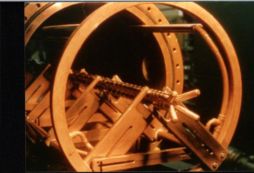
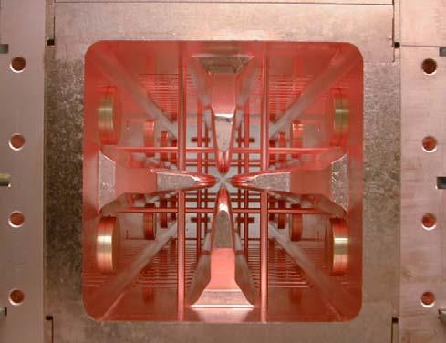
28 28 TE modes dipole mode quadrupole mode used in Radio Frequency Quadrupole
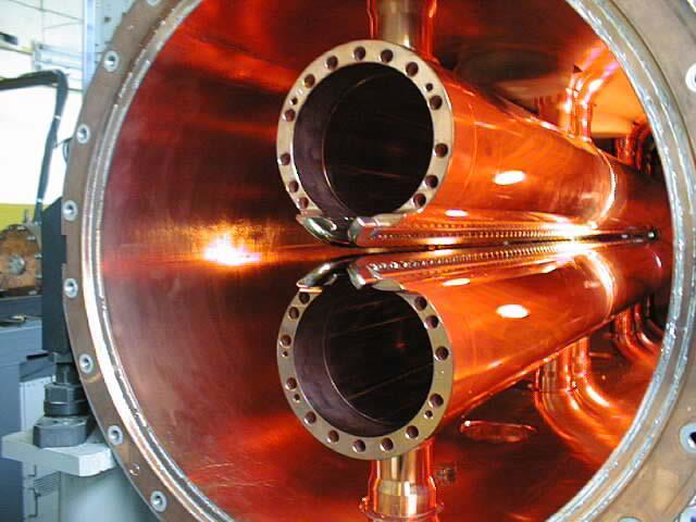
29 29 TM modes TM010 mode, most commonly used accelerating mode
30 30 cavity modes 0-mode Zero-degree phase shift from cell to cell, so fields adjacent cells are in phase. Best example is DTL. π-mode 180-degree phase shift from cell to cell, so fields in adjacent cells are out of phase. Best example is multicell superconducting cavities. π/2 mode 90-degree phase shift from cell to cell. In practice these are biperiodic structures with two kinds of cells, accelerating cavities and coupling cavities. The CCL operates in a π/2structure mode. This is the preferred mode for very long multicell cavities, because of very good field stability.

31 31 Mode 0 also called mode 2π. For synchronicity and acceleration, particles must be in phase with the E field on axis (will be discussed more in details later). During 1 RF period, the particles travel over a distance of βλ. The cell L lentgh should be: Named from the phase difference between adjacent cells. Mode L 2π βλ π/2 βλ/4 2π/3 βλ/3 π βλ/2
32 32 Selection of accelerating structures Radio Frequency Quadrupole Interdigital-H structure Drift Tube Linac Side Coupled Linac

33 Radio Frequency Quadrupoles 33


 + + DT1 DT3 DT5 t0 t1 DT2 t2 t3")

34 transverse field in an RFQ - alternating gradient focussing structure with period length (in half RF period the particles have travelled a length /2 ) + + DT1 DT3 DT5 t0 t1 DT2 t2 t3 DT4 t4 RF signal time ion beam electrodes DT1,DT3... t0,t1,t2... DT2,DT

35 35 acceleration in RFQ longitudinal modulation on the electrodes creates a longitudinal component in the TE mode
36 36 acceleration in an RFQ (1 ) 2 2 longitudinal radius of curvature modulation X aperture aperture beam axis
37 37 important parameters of the RFQ B q m 0 V a 1 f 2 1 I a m o 2 I ka I o mka ka I mka o o type of particle limited by sparking Transverse field distortion due to modulation (=1 for un-modulated electrodes) E T 0 m 2 I o m 2 ( ka) 1 I o ( mka) V 2 4 Accelerating efficiency : fraction of the field deviated in the longitudinal direction (=0 for un-modulated electrodes) cell length transit time factor
38 38...and their relation m I o 2 I ka I o mka ka I mka o o m 2 I o m 2 1 ( ka) I o ( mka) I 0 ( ka) 1 focusing efficiency accelerating efficiency a=bore radius,,=relativistic parameters, c=speed of light, f= rf frequency, I0,1=zero,first order Bessel function, k=wave number, =wavelength, m=electrode modulation, m0=rest q=charge, r= average transverse beam dimension, r0=average bore, V=vane voltage
39 39 RFQ The resonating mode of the cavity is a focusing mode Alternating the voltage on the electrodes produces an alternating focusing channel A longitudinal modulation of the electrodes produces a field in the direction of propagation of the beam which bunches and accelerates the beam Both the focusing as well as the bunching and acceleration are performed by the RF field The RFQ is the only linear accelerator that can accept a low energy CONTINOUS beam of particles 1970 Kapchinskij and Teplyakov propose the idea of the radiofrequency quadrupole ( I. M. Kapchinskii and V. A. Teplvakov, Prib.Tekh. Eksp. No. 2, 19 (1970))

40 Interdigital H structure 40

41 CNAO IH 41
42 42 Interdigital H structure TE110 mode stem on alternating side of the drift tube force a longitudinal field between the drift tubes focalisation is provided by quadrupole triplets places OUTSIDE the drift tubes or OUTSIDE the tank
43 43 IH use very good shunt impedance in the low beta region (( 0.02 to 0.08 ) and low frequency (up to 200MHz) not for high intensity beam due to long focusing period ideal for low beta heavy ion acceleration

44 Drift Tube Linac 44

45 45 DTL drift tubes Quadrupole lens Drift tube Tuning plunger Cavity shell Post coupler

46 DTL : electric field Mode is TM010
47 47 DTL E z l= The DTL operates in 0 mode for protons and heavy ions in the range = (750 kev MeV) Synchronism condition (0 mode): l c f The beam is inside the drift tubes when the electric field is decelerating The fields of the 0-mode are such that if we eliminate the walls between cells the fields are not affected, but we have less RF currents and higher shunt impedance
48 48 RFQ vs. DTL DTL can't accept low velocity particles, there is a minimum injection energy in a DTL due to mechanical constraints
49 Side Coupled Linac 49
50 50 The Side Coupled Linac multi-cell Standing Wave structure in /2 mode frequency MHz for protons (=0.5-1) Rationale: high beta cells are longer advantage for high frequencies at high f, high power (> 1 MW) klystrons available long chains (many cells) long chains high sensitivity to perturbations operation in /2 mode Side Coupled Structure: - from the wave point of view, /2 mode - from the beam point of view, mode
51 Side Coupled Linac Chain of cells, coupled via slots and off-axis coupling cells. Invented at Los Alamos in the 60 s. Operates in the /2 mode (stability). CERN SCL design: Each klystron feeds 5 tanks of 11 accelerating cells each, connected by 3-cell bridge couplers. Quadrupoles are placed between tanks.
52 Room Temperature SW structure: The LEP1 cavity 52 5-cell Standing Wave structure in mode frequency 352 MHz for electrons (=1) To increase shunt impedance : 1. noses concentrate E-field in gaps 2. curved walls reduce the path for RF currents noses BUT: to close the hole between cells would flatten the dispersion curve introduce coupling slots to provide magnetic coupling
53 53 overview Ideal range of beta frequency Particles take with CAUTION! RFQ Low!!! MHz Ions / protons IH 0.02 to MHz Ions and also protons DTL MHz Ions / protons SCL Ideal Beta=1 But as low as beta MHz protons / electrons


54 352 MHz cavity for 3 MeV protons 54

55 55 88 MHz cavity for muons 2 MW amplifier 88 MHz cavity Nose Cone (closed gap)
56 Answer 1 : Rate of change of energy 56 dp dt q E dx dt B p W momentum energy dw dt dx dt dp dt q dx dt E dx dt B Energy change via the electric field
JUAS 2018 LINACS. Jean-Baptiste Lallement, Veliko Dimov BE/ABP CERN.
 LINACS Jean-Baptiste Lallement, Veliko Dimov BE/ABP CERN jean-baptiste.lallement@cern.ch http://jlalleme.web.cern.ch/jlalleme/juas2018/ Credits Much material is taken from: Thomas Wangler, RF linear accelerators
Low-beta Structures. Maurizio Vretenar CERN BE/RF CAS RF Ebeltoft 2010
 Low-beta Structures Maurizio Vretenar CERN BE/RF CAS RF Ebeltoft. Low-beta: problems and solutions. Coupled-cell accelerating structures 3. Overview and comparison of low-beta structures 4. The Radio Frequency
High acceleration gradient. Critical applications: Linear colliders e.g. ILC X-ray FELs e.g. DESY XFEL
 High acceleration gradient Critical applications: Linear colliders e.g. ILC X-ray FELs e.g. DESY XFEL Critical points The physical limitation of a SC resonator is given by the requirement that the RF magnetic
ACCELERATION TECHNIQUES
 ACCELERATION TECHNIQUES by Joël Le DuFF (LAL-Orsay) CAS on Intermediate Accelerator Physics Course Trieste 3-4 October 005 CAS, Trieste, October 3-4 005 Bibliography Alexander W. Chao & Maury Tigner :
RF Cavity Design. Erk Jensen CERN BE/RF. CERN Accelerator School Accelerator Physics (Intermediate level) Darmstadt 2009
 Darmstadt 2009") RF Cavity Design Erk Jensen CERN BE/RF CERN Accelerator School Accelerator Physics (Intermediate level) Darmstadt 009 CAS Darmstadt '09 RF Cavity Design 1 Overview DC versus RF Basic equations: Lorentz
RF Cavity Design Erk Jensen CERN BE/RF CERN Accelerator School Accelerator Physics (Intermediate level) Darmstadt 009 CAS Darmstadt '09 RF Cavity Design 1 Overview DC versus RF Basic equations: Lorentz
Design of ESS-Bilbao RFQ Linear Accelerator
 Design of ESS-Bilbao RFQ Linear Accelerator J.L. Muñoz 1*, D. de Cos 1, I. Madariaga 1 and I. Bustinduy 1 1 ESS-Bilbao *Corresponding author: Ugaldeguren III, Polígono A - 7 B, 48170 Zamudio SPAIN, jlmunoz@essbilbao.org
The Superconducting Radio Frequency Quadrupole Structures Review
 The Superconducting Radio Frequency Quadrupole Structures Review Augusto Lombardi INFN- Laboratori Nazionali di Legnaro, via Romea 4 I-35020 Legnaro (PD) Abstract Since 1985 the idea of using the fast
A Brief History of High Power RF Proton Linear Accelerators
 f 3 o A Brief History of High Power RF Proton Linear Accelerators Introduction John C. Browne Los Alamos National Laboratory The first mention of linear acceleration was in a paper by G. Ising in 1924
Maurizio Vretenar Linac4 Project Leader EuCARD-2 Coordinator
 Maurizio Vretenar Linac4 Project Leader EuCARD-2 Coordinator Every accelerator needs a linac as injector to pass the region where the velocity of the particles increases with energy. At high energies (relativity)
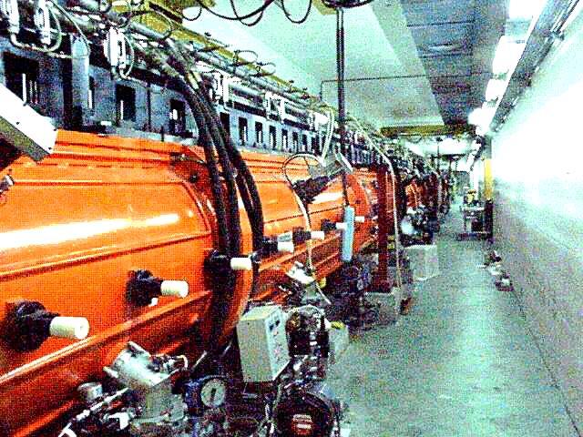
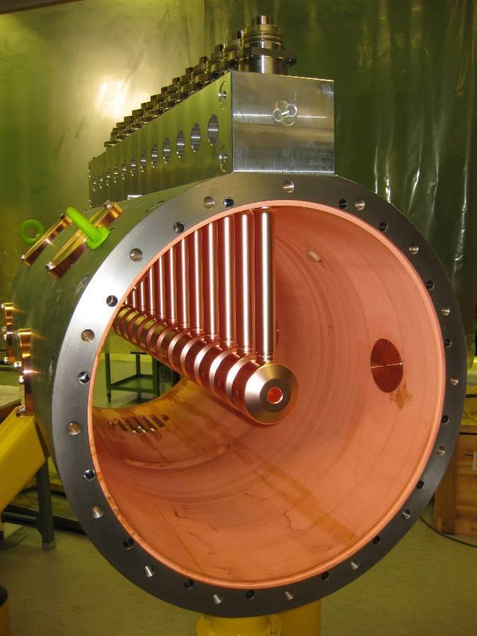
200 MHz 350 MHz 750 MHz Linac2 RFQ2 202 MHz 0.5 MeV /m Weight : 1000 kg/m Ext. diameter : 45 cm
 M. Vretenar, CERN for the HF-RFQ Working Group (V.A. Dimov, M. Garlasché, A. Grudiev, B. Koubek, A.M. Lombardi, S. Mathot, D. Mazur, E. Montesinos, M. Timmins, M. Vretenar) 1 1988-92 Linac2 RFQ2 202 MHz
REVIEW OF FAST BEAM CHOPPING F. Caspers CERN AB-RF-FB
 F. Caspers CERN AB-RF-FB Introduction Review of several fast chopping systems ESS-RAL LANL-SNS JAERI CERN-SPL Discussion Conclusion 1 Introduction Beam choppers are typically used for β = v/c values between
The design of a radio frequency quadrupole LINAC for the RIB project at VECC Kolkata
 PRAMANA cfl Indian Academy of Sciences Vol. 59, No. 6 journal of December 2002 physics pp. 957 962 The design of a radio frequency quadrupole LINAC for the RIB project at VECC Kolkata V BANERJEE 1;Λ, ALOK
Normal-conducting high-gradient rf systems
 Normal-conducting high-gradient rf systems Introduction Motivation for high gradient Order of 100 GeV/km Operational and state-of-the-art SwissFEL C-band linac: Just under 30 MV/m CLIC prototypes: Over
Development of Superconducting CH-Cavities for the EUROTRANS and IFMIF Project 1
 1 AT/P5-01-POSTER Development of Superconducting CH-Cavities for the EUROTRANS and IFMIF Project 1 F. Dziuba 2, H. Podlech 2, M. Buh 2, U. Ratzinger 2, A. Bechtold 3, H. Klein 2 2 Institute for Applied
Present and future beams for SHE research at GSI W. Barth, GSI - Darmstadt
 Present and future beams for SHE research at GSI W. Barth, GSI - Darmstadt 1. Heavy Ion Linear Accelerator UNILAC 2. GSI Accelerator Facility Injector for FAIR 3. Status Quo of the UNILAC-performance 4.
Development of superconducting crossbar-h-mode cavities for proton and ion accelerators
 PHYSICAL REVIEW SPECIAL TOPICS - ACCELERATORS AND BEAMS 13, 041302 (2010) Development of superconducting crossbar-h-mode cavities for proton and ion accelerators F. Dziuba, 1 M. Busch, 1 M. Amberg, 1 H.
CONICAL HALF-WAVE RESONATOR INVESTIGATIONS
 CONICAL HALF-WAVE RESONATOR INVESTIGATIONS E. Zaplatin, Forschungszentrum Juelich, Germany Abstract In the low energy part of accelerators the magnets usually alternate accelerating cavities. For these
R.K.YADAV. 2. Explain with suitable sketch the operation of two-cavity Klystron amplifier. explain the concept of velocity and current modulations.
 Question Bank DEPARTMENT OF ELECTRONICS AND COMMUNICATION SUBJECT- MICROWAVE ENGINEERING(EEC-603) Unit-III 1. What are the high frequency limitations of conventional tubes? Explain clearly. 2. Explain
04th - 16th August, th International Nathiagali Summer College 1 CAVITY BASICS. C. Serpico
 39th International Nathiagali Summer College 1 CAVITY BASICS C. Serpico 39th International Nathiagali Summer College 2 Outline Maxwell equations Guided propagation Rectangular waveguide Circular waveguide
RF Power Consumption in the ESS Spoke LINAC
 FREIA Report 23/ January 23 DEPARTMENT OF PHYSICS AND ASTRONOMY UPPSALA UNIVERSITY RF Power Consumption in the ESS Spoke LINAC ESS TDR Contribution V.A. Goryashko, V. Ziemann, T. Lofnes, R. Ruber Uppsala
The European Spallation Source. Dave McGinnis Chief Engineer ESS\Accelerator Division IVEC 2013
 The European Spallation Source Dave McGinnis Chief Engineer ESS\Accelerator Division IVEC 2013 Overview The European Spallation Source (ESS) will house the most powerful proton linac ever built. The average
REVIEW ON SUPERCONDUCTING RF GUNS
 REVIEW ON SUPERCONDUCTING RF GUNS D. Janssen #, A. Arnold, H. Büttig, U. Lehnert, P. Michel, P. Murcek, C. Schneider, R. Schurig, F. Staufenbiel, J. Teichert, R. Xiang, Forschungszentrum Rossendorf, Germany.
3. (a) Derive an expression for the Hull cut off condition for cylindrical magnetron oscillator. (b) Write short notes on 8 cavity magnetron [8+8]
![3. (a) Derive an expression for the Hull cut off condition for cylindrical magnetron oscillator. (b) Write short notes on 8 cavity magnetron [8+8]](/thumbs/73/68588725.jpg "3. (a) Derive an expression for the Hull cut off condition for cylindrical magnetron oscillator. (b) Write short notes on 8 cavity magnetron [8+8]") Code No: RR320404 Set No. 1 1. (a) Compare Drift space bunching and Reflector bunching with the help of Applegate diagrams. (b) A reflex Klystron operates at the peak of n=1 or 3 / 4 mode. The dc power
Code No: RR320404 Set No. 1 1. (a) Compare Drift space bunching and Reflector bunching with the help of Applegate diagrams. (b) A reflex Klystron operates at the peak of n=1 or 3 / 4 mode. The dc power
Design and RF Measurements of an X-band Accelerating Structure for the Sparc Project
 Design and RF Measurements of an X-band Accelerating Structure for the Sparc Project INFN-LNF ; UNIVERSITY OF ROME LA SAPIENZA ; INFN - MI Presented by BRUNO SPATARO Erice, Sicily, October 9-14; 2005 SALAF
DESIGN AND BEAM DYNAMICS STUDIES OF A MULTI-ION LINAC INJECTOR FOR THE JLEIC ION COMPLEX
 DESIGN AND BEAM DYNAMICS STUDIES OF A MULTI-ION LINAC INJECTOR FOR THE JLEIC ION COMPLEX Speaker: P.N. Ostroumov Contributors: A. Plastun, B. Mustapha and Z. Conway HB2016, July 7, 2016, Malmö, Sweden
Dhanalakshmi College of Engineering Department of ECE EC6701 RF and Microwave Engineering Unit 4 Part A
 Dhanalakshmi College of Engineering Department of ECE EC6701 RF and Microwave Engineering Unit 4 Part A 1. What is magnetron? [N/D-16] an electron tube for amplifying or generating microwaves, with the
5.2.3 DecayChannelSolenoids BeamDynamics Induction Linac Approach
 Chapter 5 MUON PHASE ROTATION CHANNEL Contents 5.1 Introduction... 207 5.2 rfapproach... 208 5.2.1 Introduction... 208 5.2.2 rfcavities... 209 5.2.3 DecayChannelSolenoids... 212 5.2.4 BeamDynamics... 218
INTRODUCTION TO RADIOFREQUENCY SYSTEMS FOR PARTICLE ACCELERATORS
 INTRODUCTION TO RADIOFREQUENCY SYSTEMS FOR PARTICLE ACCELERATORS Elettra-Sincrotrone Trieste S.C.p.A, Italy 39 th International Nathiagali Summer College 4 th 9 th August 2014 2 OVERVIEW Introduction Building
Advances in CW Ion Linacs
 IPAC 2015 P.N. Ostroumov May 8, 2015 Content Two types of CW ion linacs Example of a normal conducting CW RFQ Cryomodule design and performance High performance quarter wave and half wave SC resonators
Raja Ramanna Center for Advanced Technology, Indore, India
 Electromagnetic Design of g = 0.9, 650 MHz Superconducting Radiofrequency Cavity Arup Ratan Jana 1, Vinit Kumar 1, Abhay Kumar 2 and Rahul Gaur 1 1 Materials and Advanced Accelerator Science Division 2
New Tracking Gantry-Synchrotron Idea. G H Rees, ASTeC, RAL, U.K,
 New Tracking Gantry-Synchrotron Idea G H Rees, ASTeC, RAL, U.K, Scheme makes use of the following: simple synchrotron and gantry magnet lattices series connection of magnets for 5 Hz tracking one main
CST MWS simulation of the SARAF RFQ 1.5 MeV/nucleon proton/deuteron accelerator
 CST MWS simulation of the SARAF RFQ 1.5 MeV/nucleon proton/deuteron accelerator Jacob Rodnizki SARAF Soreq NRC APril 19-21 th, 2010 Outline 1. SARAF accelerator 2. Presentation of the four rods RFQ 3.
arxiv: v1 [physics.acc-ph] 21 Nov 2011
![arxiv: v1 [physics.acc-ph] 21 Nov 2011](/thumbs/72/67449824.jpg "arxiv: v1 [physics.acc-ph] 21 Nov 2011") Cavity types F. Gerigk CERN, Geneva, Switzerland arxiv:1111.4897v1 [physics.acc-ph] 21 Nov 2011 1 Introduction Abstract In the field of particle accelerators the most common use of RF cavities is to increase
Cavity types F. Gerigk CERN, Geneva, Switzerland arxiv:1111.4897v1 [physics.acc-ph] 21 Nov 2011 1 Introduction Abstract In the field of particle accelerators the most common use of RF cavities is to increase
A COUPLED RFQ-IH-DTL CAVITY FOR FRANZ: A CHALLENGE FOR RF TECHNOLOGY AND BEAM DYNAMICS
 A COUPLED RFQ-IH-DTL CAVITY FOR FRANZ: A CHALLENGE FOR RF TECHNOLOGY AND BEAM DYNAMICS R. Tiede, M. Heilmann *, D. Mäder, O. Meusel, H. Podlech, U. Ratzinger, A. Schempp, M. Schwarz, IAP, Goethe-University
cyclotron RF systems sb/cas10061/1
 cyclotron RF systems sb/cas10061/1 outline cyclotron basics resonator design techniques transmission line 3D finite element tuning power coupling RF control flat topping some specific examples sb/cas100562
Projects in microwave theory 2009
 Electrical and information technology Projects in microwave theory 2009 Write a short report on the project that includes a short abstract, an introduction, a theory section, a section on the results and
A HIGH EFFICIENCY 17GHz TW CHOPPERTRON
 1 SLAC 07 A HIGH EFFICIENCY 17GHz TW CHOPPERTRON J. Haimson and B. Mecklenburg Work performed under the auspices of the U.S. Department of Energy SBIR Grant No.DE-FG02-06ER84468 2 SLAC 07 Figure 1. Centerline
ELECTRON LINACS. Alessandro Fabris. Elettra-Sincrotrone Trieste S.C.p.A, Italy. 39 th International Nathiagali Summer College 4 th 9 th August 2014
 ELECTRON LINACS Elettra-Sincrotrone Trieste S.C.p.A, Italy 39 th International Nathiagali Summer College 4 th 9 th August 2014 2 OVERVIEW Introduction Travelling wave structures Standing wave structures
RF Design of Normal Conducting Deflecting Cavity
 RF Design of Normal Conducting Deflecting Cavity Valery Dolgashev (SLAC), Geoff Waldschmidt, Ali Nassiri (Argonne National Laboratory, Advanced Photon Source) 48th ICFA Advanced Beam Dynamics Workshop
Physics Design and Technology. Development of CSNS Accelerator
 Physics Design and Technology Development of CSNS Accelerator Second CSNS International Accelerator Technology Advisory Committee Review Meeting Institute of High Energy Physics, CAS January, 2010, Beijing,
Waveguides. Metal Waveguides. Dielectric Waveguides
 Waveguides Waveguides, like transmission lines, are structures used to guide electromagnetic waves from point to point. However, the fundamental characteristics of waveguide and transmission line waves
version 7.6 RF separator
 version 7.6 RF separator www.nscl.msu.edu/lise dnr080.jinr.ru/lise East Lansing August-2006 Contents: 1. RF SEPARATOR...3 1.1. RF SEPARATION SYSTEM (RFSS) PROPOSAL AT NSCL... 3 1.2. CONSTRUCTION OF THE
Proceedings of the 1972 Proton Linear Accelerator Conference, Los Alamos, New Mexico, USA
 STUDY OF HGH-ENERGY PROTON LNAC STRUCTURES by. G. Andreev,. M. Belugin,. G. Kulman, E. A. Mirochnik, and B. M. Pirozhenko Radiotechnical nstitute, USSR Academy of Sciences, Moscow, USSR ABSTRACT Two n2-mode
Radio frequency for particle accelerators evolution and anatomy of a technology
 Radio frequency for particle accelerators evolution and anatomy of a technology M. Vretenar CERN, Geneva, Switzerland Abstract This introductory lecture outlines the impressive progress of radio frequency
Thermionic Bunched Electron Sources for High-Energy Electron Cooling
 Thermionic Bunched Electron Sources for High-Energy Electron Cooling Vadim Jabotinski 1, Yaroslav Derbenev 2, and Philippe Piot 3 1 Institute for Physics and Technology (Alexandria, VA) 2 Thomas Jefferson
Triple-spoke compared with Elliptical-cell Cavities
 Triple-spoke compared with Elliptical-cell Cavities Ken Shepard - ANL Physics Division 2th International Workshop on RF Superconductivity Argonne National Laboratory Operated by The University of Chicago
A Synchrotron Phase Detector for the Fermilab Booster
 FERMILAB-TM-2234 A Synchrotron Phase Detector for the Fermilab Booster Xi Yang and Rene Padilla Fermi National Accelerator Laboratory Box 5, Batavia IL 651 Abstract A synchrotron phase detector is diagnostic
FAST RF KICKER DESIGN
 FAST RF KICKER DESIGN David Alesini LNF-INFN, Frascati, Rome, Italy ICFA Mini-Workshop on Deflecting/Crabbing Cavity Applications in Accelerators, Shanghai, April 23-25, 2008 FAST STRIPLINE INJECTION KICKERS
Alban Mosnier. CEA-Saclay, DSM/IRFU. Alban Mosnier Sept 29 - Oct 3, 2008 LINAC'08 Victoria British Columbia Canada page 1
 THE IFMIF 5 MW LINACS Alban Mosnier CEA-Saclay, DSM/IRFU Alban Mosnier Sept 29 - Oct 3, 2008 LINAC'08 Victoria British Columbia Canada page 1 ITER International Road Map Advanced Materials are at a critical
DEVELOPMENT OF A BETA 0.12, 88 MHZ, QUARTER WAVE RESONATOR AND ITS CRYOMODULE FOR THE SPIRAL2 PROJECT
 DEVELOPMENT OF A BETA 0.12, 88 MHZ, QUARTER WAVE RESONATOR AND ITS CRYOMODULE FOR THE SPIRAL2 PROJECT G. Olry, J-L. Biarrotte, S. Blivet, S. Bousson, C. Commeaux, C. Joly, T. Junquera, J. Lesrel, E. Roy,
Beam Commissioning and Operation of New Linac Injector for RIKEN RI Beam Factory
 Beam Commissioning and Operation of New Linac Injector for RIKEN RI Beam Factory RIKEN Nishina Center Kazunari Yamada, K. Suda, S. Arai, M. Fujimaki, T. Fujinawa, H. Fujisawa, N. Fukunishi, Y. Higurashi,
Behavior of the TTF2 RF Gun with long pulses and high repetition rates
 Behavior of the TTF2 RF Gun with long pulses and high repetition rates J. Baehr 1, I. Bohnet 1, J.-P. Carneiro 2, K. Floettmann 2, J. H. Han 1, M. v. Hartrott 3, M. Krasilnikov 1, O. Krebs 2, D. Lipka
DEVELOPMENT OF ROOM TEMPERATURE AND SUPERCONDUCTING CH-STRUCTURES H. Podlech IAP, Universität Frankfurt/Main, Germany. Abstract
 EU contract number RII3-CT-2003-506395 CARE Conf-04-011-HIPPI DEVELOPMENT OF ROOM TEMPERATURE AND SUPERCONDUCTING CH-STRUCTURES H. Podlech IAP, Universität Frankfurt/Main, Germany Abstract Abstract In
DEVELOPMENT OF CAPACITIVE LINEAR-CUT BEAM POSITION MONITOR FOR HEAVY-ION SYNCHROTRON OF KHIMA PROJECT
 DEVELOPMENT OF CAPACITIVE LINEAR-CUT BEAM POSITION MONITOR FOR HEAVY-ION SYNCHROTRON OF KHIMA PROJECT Ji-Gwang Hwang, Tae-Keun Yang, Seon Yeong Noh Korea Institute of Radiological and Medical Sciences,
SRF Advances for ATLAS and Other β<1 Applications
 SRF Advances for ATLAS and Other β
A Design of a 3rd Harmonic Cavity for the TTF 2 Photoinjector
 TESLA-FEL 2002-05 A Design of a 3rd Harmonic Cavity for the TTF 2 Photoinjector J. Sekutowicz, R. Wanzenberg DESY, Notkestr. 85, 22603 Hamburg, Germany W.F.O. Müller, T. Weiland TEMF, TU Darmstadt, Schloßgartenstr.
QUARTER WAVE COAXIAL LINE CAVITY FOR NEW DELHI LINAC BOOSTER*
 QUARTER WAVE COAXIAL LINE CAVITY FOR NEW DELHI LINAC BOOSTER* P.N. Prakash and A.Roy Nuclear Science Centre, P.O.Box 10502, New Delhi 110 067, INDIA and K.W.Shepard Physics Division, Argonne National Laboratory,
Accelerator Complex U70 of IHEP-Protvino: Status and Upgrade Plans
 INSTITUTE FOR HIGH ENERGY PHYSICS () Protvino, Moscow Region, 142281, Russia Accelerator Complex U70 of -Protvino: Status and Upgrade Plans (report 4.1-1) Sergey Ivanov, on behalf of the U70 staff September
Progress in High Gradient Accelerator Research at MIT
 Progress in High Gradient Accelerator Research at MIT Presented by Richard Temkin MIT Physics and Plasma Science and Fusion Center May 23, 2007 MIT Accelerator Research Collaborators MIT Plasma Science
Magnetron. Physical construction of a magnetron
 anode block interaction space cathode filament leads Magnetron The magnetron is a high-powered vacuum tube that works as self-excited microwave oscillator. Crossed electron and magnetic fields are used
SC Cavity Development at IMP. Linac Group Institute of Modern Physics, CAS IHEP, Beijing,CHINA
 SC Cavity Development at IMP Linac Group Institute of Modern Physics, CAS 2011-09-19 IHEP, Beijing,CHINA Outline Ø Superconducting Cavity Choice Ø HWR Cavity Design EM Design & optimization Mechanical
Beam BreakUp at Daresbury. Emma Wooldridge ASTeC
 Beam BreakUp at Daresbury Emma Wooldridge ASTeC Outline The causes of Beam Breakup (BBU) Types of BBU Why investigate BBU? Possible solutions Causes of BBU There are four main causes. Interaction with
Project X Cavity RF and mechanical design. T. Khabiboulline, FNAL/TD/SRF
 Project X Cavity RF and mechanical design T. Khabiboulline, FNAL/TD/SRF TTC meeting on CW-SRF, 2013 Project X Cavity RF and mechanical design T 1 High ß Low ß 0.5 HWR SSR1 SSR2 0 1 10 100 1 10 3 1 10 4
Attosecond Diagnostics of Muti GeV Electron Beams Using W Band Deflectors
 Attosecond Diagnostics of Muti GeV Electron Beams Using W Band Deflectors V.A. Dolgashev, P. Emma, M. Dal Forno, A. Novokhatski, S. Weathersby SLAC National Accelerator Laboratory FEIS 2: Femtosecond Electron
Superconducting RF Cavity Performance Degradation after Quenching in Static Magnetic Field
 Superconducting RF Cavity Performance Degradation after Quenching in Static Magnetic Field T. Khabiboulline, D. Sergatskov, I. Terechkine* Fermi National Accelerator Laboratory (FNAL) *MS-316, P.O. Box
5.5 SNS Superconducting Linac
 JP0150514 ICANS - XV 15 th Meeting of the International Collaboration on Advanced Neutron Sources November 6-9, 2000 Tsukuba, Japan Ronald M. Sundelin Jefferson Lab* 5.5 SNS Superconducting Linac 12000
LOW-β SC RF CAVITY INVESTIGATIONS
 LOW-β SC RF CAVITY INVESTIGATIONS E. Zaplatin, W. Braeutigam, R. Stassen, FZJ, Juelich, Germany Abstract At present, many accelerators favour the use of SC cavities as accelerating RF structures. For some
DQW HOM Coupler for LHC
 DQW HOM Coupler for LHC J. A. Mitchell 1, 2 1 Engineering Department Lancaster University 2 BE-RF-BR Section CERN 03/07/2017 J. A. Mitchell (PhD Student) HL LHC UK Jul 17 03/07/2017 1 / 27 Outline 1 LHC
Particle Simulation of Lower Hybrid Waves in Tokamak Plasmas
 Particle Simulation of Lower Hybrid Waves in Tokamak Plasmas J. Bao 1, 2, Z. Lin 2, A. Kuley 2, Z. X. Wang 2 and Z. X. Lu 3, 4 1 Fusion Simulation Center and State Key Laboratory of Nuclear Physics and
Stability Analysis of C-band 500-kW Klystron with Multi-cell. Output cavity
 Stability Analysis of C-band 5-kW Klystron with Multi-cell Output cavity Jihyun Hwang Department of Physics, POSTECH, Pohang 37673 Sung-Ju Park and Won Namkung Pohang Accelerator Laboratory, Pohang 37874
COUPLER DESIGN CONSIDERATIONS FOR THE ILC CRAB CAVITY
 COUPLER DESIGN CONSIDERATIONS FOR THE ILC CRAB CAVITY C. Beard 1), G. Burt 2), A. C. Dexter 2), P. Goudket 1), P. A. McIntosh 1), E. Wooldridge 1) 1) ASTeC, Daresbury laboratory, Warrington, Cheshire,
RF Systems I. Erk Jensen, CERN BE-RF
 RF Systems I Erk Jensen, CERN BE-RF Introduction to Accelerator Physics, Prague, Czech Republic, 31 Aug 12 Sept 2014 Definitions & basic concepts db t-domain vs. ω-domain phasors 8th Sept, 2014 CAS Prague
Room Temperature High Repetition Rate RF Structures for Light Sources
 Room Temperature High Repetition Rate RF Structures for Light Sources Sami G. Tantawi SLAC Claudio Pellegrini, R. Ruth, J. Wang. V. Dolgashev, C. Bane, Zhirong Huang, Jeff Neilson, Z. Li Outline Motivation
STATUS OF THE ILC CRAB CAVITY DEVELOPMENT
 STATUS OF THE ILC CRAB CAVITY DEVELOPMENT SLAC-PUB-4645 G. Burt, A. Dexter, Cockcroft Institute, Lancaster University, LA 4YR, UK C. Beard, P. Goudket, P. McIntosh, ASTeC, STFC, Daresbury laboratories,
HITACHI Proton Therapy System with Spot Scanning
 Workshop on Hadron Therapy of Cancer 27 th April, Erice, Sicily, Italy HITACHI Proton Therapy System with Spot Scanning Kazuo Hiramoto Energy & Environmental Systems Laboratory, Hitachi, Ltd. Contents
Status and Plans for the 805 MHz Box Cavity MuCool RF Workshop III 07/07/09 Al Moretti
 Status and Plans for the 805 MHz Box Cavity MuCool RF Workshop III 07/07/09 Al Moretti 7/6/2009 1 Outline : Description of the Box cavity Concept. Box Cavity Summary Plans. HFSS Models of orthogonal and
Resonant Excitation of High Order Modes in the 3.9 GHz Cavity of LCLS-II Linac
 Resonant Excitation of High Order Modes in the 3.9 GHz Cavity of LCLS-II Linac LCLS-II TN-16-05 9/12/2016 A. Lunin, T. Khabiboulline, N. Solyak, A. Sukhanov, V. Yakovlev April 10, 2017 LCLSII-TN-16-06
S-Band Side Coupled Linac Maria Rosaria Masullo and Vittorio Giorgio Vaccaro
 S-Band Side Coupled Linac Maria Rosaria Masullo and Vittorio Giorgio Vaccaro Istituto Nazionale di Fisica Nucleare - Section of Napoli Università degli Studi di Napoli Federico II, Napoli Thanks to all
A High Gradient Coreless Induction Method of Acceleration
 A High Gradient Coreless Induction Method of Acceleration A. Krasnykh (SLAC National Accelerator Lab, USA) and A. Kardo-Sysoev (Ioffe PTI, St. Petersburg, Russia) ICFA Workshop on Novel Concepts, 2009
Linear Particle Accelerator Control Performance
 Linear Particle Accelerator Control Performance 2007 ExpertTune-TiPS Conference April 17-19, 2007 Austin, TX Johnny Tang Overview of the Spallation Neutron Source Accelerator J. Tang 2 Overview of the
UNIT - V WAVEGUIDES. Part A (2 marks)
") Part A (2 marks) UNIT - V WAVEGUIDES 1. What is the need for guide termination? (Nov / Dec 2011) To avoid reflection loss. The termination should provide a wave impedance equal to that of the transmission
Part A (2 marks) UNIT - V WAVEGUIDES 1. What is the need for guide termination? (Nov / Dec 2011) To avoid reflection loss. The termination should provide a wave impedance equal to that of the transmission
DESIGN STUDY OF A 176 MHZ SRF HALF WAVE RESONATOR FOR THE SPIRAL-2 PROJECT
 DESIGN STUDY OF A 176 MHZ SRF HALF WAVE RESONATOR FOR THE SPIRAL-2 PROJECT J-L. Biarrotte*, S. Blivet, S. Bousson, T. Junquera, G. Olry, H. Saugnac CNRS / IN2P3 / IPN Orsay, France Abstract In November
CLIC Power Extraction and Transfer Structure. (2004)
") CLIC Power Extraction and Transfer Structure. (24) CLIC linac subunit layout: CLIC accelerating Structure (HDS) Main beam 3 GHz, 2 MW per structure Drive beam (64 A) CLIC Power Extraction and Transfer
CLIC Power Extraction and Transfer Structure. (24) CLIC linac subunit layout: CLIC accelerating Structure (HDS) Main beam 3 GHz, 2 MW per structure Drive beam (64 A) CLIC Power Extraction and Transfer
CERN EUROPEAN ORGANIZATION FOR NUCLEAR RESEARCH INVESTIGATION OF A RIDGE-LOADED WAVEGUIDE STRUCTURE FOR CLIC X-BAND CRAB CAVITY
 CERN EUROPEAN ORGANIZATION FOR NUCLEAR RESEARCH CLIC Note 1003 INVESTIGATION OF A RIDGE-LOADED WAVEGUIDE STRUCTURE FOR CLIC X-BAND CRAB CAVITY V.F. Khan, R. Calaga and A. Grudiev CERN, Geneva, Switzerland.
Lattice Design for PRISM-FFAG. A. Sato Osaka University for the PRISM working group
 Lattice Design for PRISM-FFAG A. Sato Osaka University for the PRISM working group contents PRISM overview PRISM-FFAG dynamics study & its method PRISM Phase Rotated Intense Slow Muon source Anticipated
Low-Level RF. S. Simrock, DESY. MAC mtg, May 05 Stefan Simrock DESY
 Low-Level RF S. Simrock, DESY Outline Scope of LLRF System Work Breakdown for XFEL LLRF Design for the VUV-FEL Cost, Personpower and Schedule RF Systems for XFEL RF Gun Injector 3rd harmonic cavity Main
Automatic phase calibration for RF cavities using beam-loading signals. Jonathan Edelen LLRF 2017 Workshop (Barcelona) 18 Oct 2017
 18 Oct 2017") Automatic phase calibration for RF cavities using beam-loading signals Jonathan Edelen LLRF 2017 Workshop (Barcelona) 18 Oct 2017 Introduction How do we meet 10-4 energy stability for PIP-II? 2 11/9/2017
Automatic phase calibration for RF cavities using beam-loading signals Jonathan Edelen LLRF 2017 Workshop (Barcelona) 18 Oct 2017 Introduction How do we meet 10-4 energy stability for PIP-II? 2 11/9/2017
Packaging of Cryogenic Components
 Packaging of Cryogenic Components William J. Schneider Senior Mechanical Engineer Emeritus November 19-23 2007 1 Packaging of Cryogenic Components Day one Introduction and Overview 2 What is important?
MULTIMEDIA UNIVERSITY FACULTY OF ENGINEERING LAB SHEET
 MULTIMEDIA UNIVERSITY FACULTY OF ENGINEERING LAB SHEET ELECTROMAGNETIC THEORY EMF016 MW1 MICROWAVE FREQUENCY AND SWR MEASUREMENTS EM Theory Faculty of Engineering, Multimedia University 1 EXPERIMENT MW1:
Booster High-level RF Frequency Tracking Improvement Via the Bias-Curve Optimization
 FERMILAB-TM-227-AD Booster High-level RF Frequency Tracking Improvement Via the Bias-Curve Optimization Xi Yang Fermi National Accelerator Laboratory Box 5, Batavia IL 651 Abstract It is important to improve
ADVANCES IN CW ION LINACS*
 Abstract Substantial research and development related to continuous wave (CW) proton and ion accelerators is being performed at ANL. A 4-meter long 60.625-MHz normal conducting (NC) CW radio frequency
ACCELERATOR PHYSICS OF HIGH INTENSITY PROTON LINACS
 ACCELERATOR PHYSICS OF HIGH INTENSITY PROTON LINACS K. Bongardt and M. Pabst, Forschungszentrum Jülich GmbH, 52425 Jülich, Germany Abstract The accelerator physics of high intensity linacs, either pulsed
MEASURES TO REDUCE THE IMPEDANCE OF PARASITIC RESONANT MODES IN THE DAΦNE VACUUM CHAMBER
 Frascati Physics Series Vol. X (1998), pp. 371-378 14 th Advanced ICFA Beam Dynamics Workshop, Frascati, Oct. 20-25, 1997 MEASURES TO REDUCE THE IMPEDANCE OF PARASITIC RESONANT MODES IN THE DAΦNE VACUUM
Accuracy of Microwave Cavity Perturbation Measurements
 918 IEEE TRANSACTIONS ON MICROWAVE THEORY AND TECHNIQUES, VOL. 49, NO. 5, MAY 2001 Accuracy of Microwave Cavity Perturbation Measurements Richard G. Carter, Member, IEEE Abstract Techniques based on the
Progress Report on SIMULINK Modelling of RF Cavity Control for SPL Extension to LINAC4
 EUROPEAN ORGANIZATION FOR NUCLEAR RESEARCH European Laboratory for Particle Physics slhc Project slhc Project Report 0054 Progress Report on SIMULINK Modelling of RF Cavity Control for SPL Extension to
Converters for Cycling Machines
 Converters for Cycling Machines Neil Marks, DLS/CCLRC, Daresbury Laboratory, Warrington WA4 4AD, U.K. DC and AC accelerators; Contents suitable waveforms in cycling machines; the magnet load; reactive
Appendix 3-B: The AJ-Disk 1-D Large Signal Code (A. Jensen)
") Introduction & User s Guide Appendix 3-B: The AJ-Disk 1-D Large Signal Code (A. Jensen) The following is an introduction and user s tutorial for AJ Disk. Each step necessary to open AJ Disk and simulate
Introduction & User s Guide Appendix 3-B: The AJ-Disk 1-D Large Signal Code (A. Jensen) The following is an introduction and user s tutorial for AJ Disk. Each step necessary to open AJ Disk and simulate
Third Harmonic Cavity Status
 Third Harmonic Cavity Status General parameters Cavity design Main coupler calculation HOM analysis and HOM coupler design Lorentz Forces and Stress analysis Summary General parameters Third harmonic cavity
Performance of the TTF Photoinjector Laser System
 Performance of the TTF Photoinjector Laser System S. Schreiber, DESY Laser Issues for Electron Photoinjectors, October 23-25, 22, Stanford, California, USA & I. Will, A. Liero, W. Sandner, MBI Berlin Overview
INSTITUTE OF AERONAUTICAL ENGINEERING (Autonomous) Dundigal, Hyderabad
 Dundigal, Hyderabad") INSTITUTE OF AERONAUTICAL ENGINEERING (Autonomous) Dundigal, Hyderabad - 500 043 ELECTRONICS AND COMMUNICATION ENGINEERING TUTORIAL BANK Name : MICROWAVE ENGINEERING Code : A70442 Class : IV B. Tech I
INSTITUTE OF AERONAUTICAL ENGINEERING (Autonomous) Dundigal, Hyderabad - 500 043 ELECTRONICS AND COMMUNICATION ENGINEERING TUTORIAL BANK Name : MICROWAVE ENGINEERING Code : A70442 Class : IV B. Tech I