Low-beta Structures. Maurizio Vretenar CERN BE/RF CAS RF Ebeltoft 2010
|
|
|
- Elijah Kelley
- 6 years ago
- Views:
Transcription

1 Low-beta Structures Maurizio Vretenar CERN BE/RF CAS RF Ebeltoft. Low-beta: problems and solutions. Coupled-cell accelerating structures 3. Overview and comparison of low-beta structures 4. The Radio Frequency Quadrupole (from the RF point of view)
2 Definitions Low-beta structures are used in linear accelerators for protons and ions, where the velocity of the particle beam increases with energy (not for electrons, which are immediately relativistic, nor for synchrotrons where particle velocity is nearly constant). The periodicity of the RF structure must match the increasing particle velocity development of a complete panoply of structures (NC and SC) with different features. Protons and ions: at the beginning of the acceleration, beta (=v/c) is rapidly increasing, but after few hundred MeV s (protons) relativity prevails over classical mechanics (β~) and particle velocity tends to saturate at the speed of light. (v/c) (v/c)^ electrons protons (protons, classical mechanics) Low-beta structures are specifically designed for the increasing velocity range Kinetic Energy [MeV] W
3 Synchronicity Let s assume that we want to accelerate a low-beta beam with an array of RF cavities. Beam of protons or ions, β= v/c ~..5 d RF cavity E-field on gap of cavity i : E i = E i cos (ωt + φ ι ), energy gain W i = ev i Tcosφ ι For the beam to cross each gap on the same RF phase, then ωτ= φ (τ=time to travel from one cavity to the next; φ=difference in phase between adjacent cavities) d φ = ωτ = ω βc d = π βλ φ π = d βλ distance between cavities and phase of each cavity are correlated When β increases during acceleration, either the phase difference between cavities φ must decrease or their distance d must increase. 3
4 Architectures for low-beta So, where is the problem? If we control the phase of each cavity (connected to an individual amplifier) we can easily implement the required phase difference between cavities but this can become very expensive! In fact:. Short single-gap cavities have a low shunt-impedance (high wall loss for a small voltage);. Individual RF amplifiers for each small cavity are very expensive. d This type of cavity array is used only in few special cases (if one needs a very large beta acceptance) Low-beta structures are usually multi-gap, multi-cell structures, fed from the same power source. Instead of changing the phase to keep synchronism we change the distance between gaps. 4
5 Coupled cell structures φ π = d βλ d = const. φ variable Individual cavity system distance between cavities constant, each cavity fed by an individual RF source, phase of each cavity adjusted to keep synchronism used for linac required to operate with different ions or at different energies. Flexible but expensive! φ = const. d variable d βλ Coupled cell system a single RF source feeds a large number of cells (up to ~!) - the phase between adjacent cells is defined by the coupling and the distance between cells increases to keep synchronism is the standard accelerating structure for linacs. Once the geometry is 5 defined, it can accelerate only one type of ion for a given energy range. Effective but not flexible. d Better, but problems:. create a coupling ;. create a mechanical and RF structure with increasing cell length.
 each optimized for a certain range of energy and type of particle, explaining the large number of low-beta")
6 The low-beta zoo Between these extreme case (array of independently phased single-gap cavities / single long chain of coupled cells with lengths matching the particle beta) there can be a large number of variations (number of gaps per cavity, length of the cavity, type of coupling) each optimized for a certain range of energy and type of particle, explaining the large number of low-beta structures used in practice. The goal of this lecture is to provide the background to understand the main features try a zoological classification of structures Coupling Cells Bridge Coupler Quadrupole lens Drift tube Tuning plunger DTL Quadrupole SCL Cavity shell Post coupler CCDTL PIMS CH 6
7 . Coupled cell systems 7
8 Coupling resonant cavities. Magnetic coupling: open slots in regions of high magnetic field B-field can couple from one cell to the next How can we couple together a chain of n reentrant (=loaded pillbox) accelerating cavities?. Electric coupling: enlarge the beam aperture E-field can couple from one cell to the next The effect of the coupling is that the cells no longer resonate independently, but will have common resonances with well defined field patterns. 8
9 Chains of coupled resonators What is the relative phase and amplitude between cells in a chain of coupled cavities? A linear chain of accelerating cells can M R M be represented as a sequence of resonant circuits magnetically coupled. L L Individual cavity resonating at ω frequenci(es) of the coupled system? Resonant circuit equation for circuit i (neglecting the losses, R ): Ii( jωl + ) + jωkl( Ii + Ii+ ) = jωc L I i L C ω = / LC M k L L = kl = Dividing both terms by jωl: X i ω k ( ) + ( X + ) = i X i+ ω General response term, (stored energy) /, can be voltage, E-field, B-field, etc. General resonance term Contribution from adjacent oscillators 9
10 The Coupled-system Matrix X i ω k ( ) + ( X + ) i X i+ ω i =,.., N = A chain of N+ resonators is described by a (N+)x(N+) matrix: ω ω k... k ω ω... k... k ω ω X X... X N This matrix equation has solutions only if = or M X det M = = Eigenvalue problem!. System of order (N+) in ω only N+ frequencies will be solution of the problem ( eigenvalues, corresponding to the resonances) a system of N coupled oscillators has N resonance frequencies an individual resonance opens up into a band of frequencies.. At each frequency ω i will correspond a set of relative amplitudes in the different cells (X, X,, X N ): the eigenmodes or modes.
11 Modes in a linear chain of oscillators We can find an analytical expression for eigenvalues (frequencies) and eigenvectors (modes): Frequencies of the coupled system : ω ω =, q = N q π q,.., + k cos N the index q defines the number of the solution is the mode index Each mode is characterized by a phase πq/n. Frequency vs. phase of each mode can be plotted as a dispersion curve ω=f(φ):.each mode is a point on a sinusoidal curve..modes are equally spaced in phase..5 ω. / -k frequency wq.5 ω ω / +k π/ π phase shift per oscillator φ=πq/n The eigenvectors = relative amplitude of the field in the cells are: X ( q) i = ( const) π qi cos N e jω t q q =,..., N STANDING WAVE MODES, defined by a phase πq/n corresponding to the phase shift between an oscillator and the next one adjacent cells (gap) have a fixed phase difference πq/n=φ.
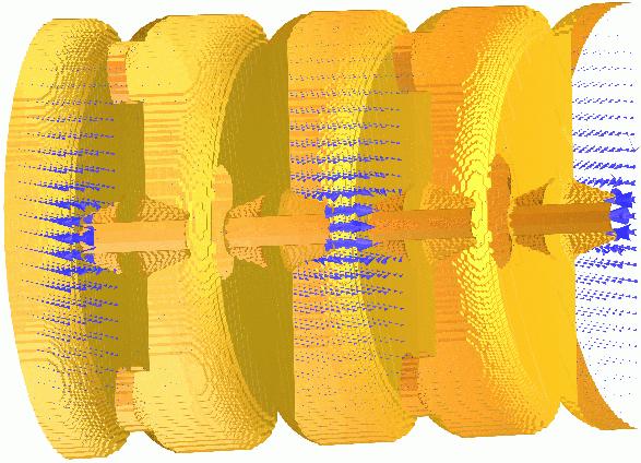
12 q= Acceleration on the normal modes of a 7-cell structure X ( q) i = ( const) π qi cos N e jω t q q =,..., N d Φ = π, π = π, d = βλ βλ ω = ω / +k (or π) mode, acceleration if d = βλ Remember the phase relation! d φ = π βλ Intermediate modes π/ q=n/ π q=n π d π βλ Φ =, π =, d = βλ 4 ω = ω π/ mode, acceleration if d = βλ/4 d βλ Φ = π, π = π, d = βλ ω = ω / -k π mode, acceleration if d = βλ/, Note: Field always maximum in first and last cell!
13 Practical linac accelerating structures Some coupled cell modes provide a fixed phase difference between cells that can be used for acceleration. Note that our relations depend only on the cell frequency ω, not on the cell length d! ω ω =, q = N q q,..., ( q) π qn jωq t π X n = ( const) cos e q =,..., N + k cos N N As soon as we keep the frequency of each cell constant, we can change the cell length following any acceleration (β) profile! Example: The Drift Tube Linac (DTL) MeV, β =.45 d (L, C ) LC ~ const ω ~ const d 5 MeV, β =.3 Chain of many (up to!) accelerating cells operating in the mode. The ultimate coupling slot: no wall between the cells (but electric coupling )! Each cell has a different length, but the cell frequency remains constant correct field and phase profile, the EM fields don t see that the cell length is 3 changing!
14 The Drift Tube Linac A DTL tank with N drift tubes will have N modes of oscillation. For acceleration, we choose the -mode, the lowest of the band. All cells (gaps) are in phase, then φ=π d φ = π = π βλ d = βλ Distance between gaps must be βλ The other modes in the band (and many others!) are still present. If mode separation >> bandwidth, they are not visible at the operating frequency, but they can come out in case of frequency errors between the cells (mechanical errors or others) TM modes Stem modes PC modes operating -mode MHz mode number mode distribution in a DTL tank (operating frequency 35 MHz, are plotted all frequencies < 6 MHz) 4
15 DTL construction Quadrupole lens Drift tube Tuning plunger Standing wave linac structure for protons and ions, β=.-.5, f=- 4 MHz Drift tubes are suspended by stems (no net RF current on stem) Coupling between cells is maximum (no slot, fully open!) Cavity shell Post coupler The -mode allows a long enough cell (d=βλ) to house focusing quadrupoles inside the drift tubes! E-field B-field 5
 and provides an energy gain of MeV.")
 quadrupoles inside drift tubes.")
16 Examples of DTL Top; CERN Linac Drift Tube Linac accelerating tank ( MHz). The tank is 7m long (diameter m) and provides an energy gain of MeV. Left: DTL prototype for CERN Linac4 (35 MHz). Focusing is provided by (small) quadrupoles inside drift tubes. Length of drift tubes (cell length) increases with proton velocity. 6
 7 cells magnetically coupled, 35 MHz Operating in π-mode, cell length βλ/.")

17 A 7-cell magnetically-coupled structure PIMS = Pi-Mode Structure, will be used in Linac4 at CERN to accelerate protons from to 6 MeV (β >.4) 7 cells magnetically coupled, 35 MHz Operating in π-mode, cell length βλ/ RF input Frequency Cells in a cavity have the same length. When more cavities are used for acceleration, the cells are longer from one cavity to the next, to follow the increase in beam velocity. 7
18 Coupling between cavities In the PIMS, cells are coupled via a slot in the walls. But what is the meaning of coupling, and how can we achieve a given coupling? Simplest case: resonators coupled via a slot Described by a system of equations: ω X ( ) + kx ω ω kx + X ( ) ω ω = c, = ω = + k or ω ω k k ω ω If ω =ω =ω, usual solutions (mode and mode π): with X X = and ω X X c, = ω = k with Mode + + (field in phase in the resonators) and mode + - (field with opposite phase) Taking the difference between the solutions (squared), approximated for k<< ω c, ω ω c, = k + k k or X X = c, ω ω The coupling k is equal to the difference between highest and lowest frequencies. k is the bandwidth of the coupled system. ω E-field mode E-field mode c, k
19 More on coupling Solving the previous equations allowing a different frequency for each cell, we can plot the frequencies of the coupled system as a function of the frequency of the first resonator, keeping the frequency of the second constant, for different values of the coupling k. Coupled freqeuencies [MHz] Frequency f [MHz] For an elliptical coupling slot: k F l 3 H U H U maximum separation when f=f F = slot form factor l = slot length (in the direction of H) H = magnetic field at slot position U = stored energy f f Coupling only when the resonators are close in frequency. - For f =f, maximum spacing between the frequencies (=kf ) The coupling k is: Proportional to the 3 rd power of slot length. Inv. proportional to the stored energies. fc fc fc fc fc fc case of 3 different coupling factors (.%, 5%, %)
20 Long chains of linac cells To reduce RF cost, linacs use high-power RF sources feeding a large number of coupled cells (DTL: 3-4 cells, other high-frequency structures can have > cells). But long linac structures (operating in or π mode) become extremely sensitive to mechanical errors: small machining errors in the cells can induce large differences in the accelerating field between cells. ω E mode π/ π k mode π
21 Stability of long chains of coupled resonators Mechanical errors differences in frequency between cells to respect the new boundary conditions the electric field will be a linear combination of all modes, with weight f f (general case of small perturbation to an eigenmode system, the new solution is a linear combination of all the individual modes) The nearest modes have the highest effect, and when there are many modes on the dispersion curve (number of modes = number of cells, but the total bandwidth is fixed = k!) the difference in E-field between cells can be extremely high. mode mode π/ mode π/3 mode π ω E π/ π k z
22 Stabilization of long chains: the π/ mode Solution: Long chains of linac cells can be operated in the π/ mode, which is intrinsically insensitive to differences in the cell frequencies. ω Perturbing mode mode π/ π/ π k Operating mode Perturbing mode Contribution from adjacent modes proportional to with the sign!!! f f The perturbation will add a component E/(f -f o ) for each of the nearest modes. Contributions from equally spaced modes in the dispersion curve will cancel each other.

23 The Side Coupled Linac To operate efficiently in the π/ mode, the cells that are not excited can be removed from the beam axis they are called coupling cells, as for the Side Coupled Structure. E-field Example: the Cell-Coupled Linac at the SNS linac, 85 MHz, - MeV, > cells/module 3


 Annular ring")
24 Examples of π/ structures π/-mode in a coupled-cell structure On axis Coupled Structure (OCS) Annular ring Coupled Structure (ACS) Side Coupled Structure (SCS) 4
 Series of DTL-like tanks with 3 cells (operating in -mode), coupled by coupling")

25 The Cell-Coupled Drift Tube Linac DTL-like tank ( drift tubes) Coupling cell DTL-like tank ( drift tubes) Series of DTL-like tanks with 3 cells (operating in -mode), coupled by coupling cells (operation in π/ mode) 35 MHz, will be used for the CERN Linac4 in the range 4- MeV. The coupling cells leave space for focusing quadrupoles between tanks. Waveguide input coupler 5


26 The DTL with post-couplers Postcoupler In a DTL, can be added post-couplers on a plane perpendicular to the stems. Each post is a resonator that can be tuned to the same frequency as the main -mode and coupled to this mode to double the chain of resonators allowing operation in stabilised π/-like mode! The equivalent circuit becomes extremely complicated and tuning is an issue, but π/ stabilization is very effective and allows having long DTL tanks! TM modes Stem modes PC modes MHz mode number 6
 H f <~ 3 MHz β ~ <.3 EA V Y IO N S H () 5-6 MHz.")
27 H-mode structures R F Q f <~ β ~ < H MHz.3 Low and Medium - β Structures in H-Mode Operation H - 4 MHz β ~ <. LIGHT IONS Interdigital-H Structure Operates in TE mode Transverse E-field deflected by adding drift tubes Used for ions, β<.3 D T L H () H f <~ 3 MHz β ~ <.3 EA V Y IO N S H () 5-6 MHz.6 β < ~ CH Structure operates in TE, used for protons at β<.6 High ZT but more difficult beam dynamics (no space for quads in drift tubes) HSI IH DTL, 36 MHz B -- E Interdigital H-Mode (IH) B ++ E Crossbar H-Mode (CH) 7
28 Comparison of structures Shunt impedance Main figure of merit is the shunt impedance Ratio between energy gain (square) and power dissipation, is a measure of the energy efficiency of a structure. Depends on the beta, on the energy and on the mode of operation. However, the choice of the best accelerating structure for a certain energy range depends also on beam dynamics and on construction cost. A fair comparison of shuntimpedances for different lowbeta structures done in 5-8 by the HIPPI EU-funded Activity. In general terms, a DTL-like structure is preferred at lowenergy, and π-mode structures at high-energy. CH is excellent at very low energies (ions). 8
29 3. Superconducting lowbeta structures 9
30 General architecture For Superconducting structures:. Shunt impedance and power dissipation are not a concern.. Power amplifiers are small (and relatively inexpensive) solid-state units. can be used the independent cavity architecture, which allows some flexibility in the range of beta and e/m of the particles to be accelerated. d In particular, SC structures are convenient for machines operating at high duty cycle. At low duty, static cryogenic losses are predominant (many small cavities!) However, even for SC linacs single-gap cavities are expensive to produce (and lead to larger cryogenic dissipation) double or triple-gap resonators are commonly used! 3
 is guaranteed only for one energy/velocity, while for easiness of construction a linac is composed by series of identical QWR s reduction of energy gain")
31 Quarter Wave Resonators Simple -gap cavities commonly used in SC version (lead, niobium, sputtered niobium) for low beta protons or ion linacs, where ~CW operation is required. Synchronicity (distance βλ/ between the gaps) is guaranteed only for one energy/velocity, while for easiness of construction a linac is composed by series of identical QWR s reduction of energy gain for off-energy cavities, Transit Time Factor (= ratio between actual energy gained and maximum energy gain) curves as below: phase slippage 3


32 An example of SC linac The goal is flexibility: acceleration of different ions (e/m) at different energies need to change phase relation for each ion-energy RF cavity focusing solenoid REX-HIE linac (to be built at CERN - superconducting) Post-accelerator of radioactive ions sections of identical equally spaced cavities Quarter-wave RF cavities, gaps + cavities with individual RF amplifiers, 8 focusing solenoids Energy. MeV/u, accelerates different A/m beam 3


33 The Spoke cavity Another option: Double or triple-spoke cavity, can be used at higher energy (- MeV for protons and triple-spoke). HIPPI Triple-spoke cavity prototype built at FZ Jülich, now under test at IPNO 33
![The superconducting zoo Spoke (low beta) [FZJ, Orsay]](/docs-images/78/77299605/images/34-0.jpg "CH (low/medium beta) [IAP-FU] QWR (low beta) [LNL,")
![etc.] HWR (low beta) [FZJ, LNL, Orsay] Reentrant](/docs-images/78/77299605/images/34-2.jpg "[LNL] Superconducting linacs for low and medium beta")


34 The superconducting zoo Spoke (low beta) [FZJ, Orsay] CH (low/medium beta) [IAP-FU] QWR (low beta) [LNL, etc.] HWR (low beta) [FZJ, LNL, Orsay] Reentrant [LNL] Superconducting linacs for low and medium beta ions are made of multigap ( to 4) individual cavities, spaced by focusing elements. Advantages: can be individually phased linac can accept different ions Allow more space for focusing ideal for low β CW proton linacs 34
35 4. The Radio Frequency Quadrupole 35

36 The Radio Frequency Quadrupole (RFQ) RFQ = Electric quadrupole focusing channel + bunching + acceleration 36
37 The basic RFQ principle. Four electrodes (vanes) between which is excited a quadrupole RF mode Electric focusing channel. +. The vanes have a longitudinal modulation with period βλ longitudinal component of the electric field. The modulation corresponds exactly to a series of RF gaps and can provide acceleration The modulation period is slightly adjusted to control the phase of the beam in each cell, the amplitude of the modulation is changed to change the accelerating gradient adiabatic bunching channel. + Opposite vanes (8º) Adjacent vanes (9º) 37


38 The RFQ resonator How to produce on the electrodes the quadrupole RF field? main families of resonators: 4-vane and 4-rod structures plus some more exotic options (split-ring, double-h, etc.) 38
39 The 4-vane RFQ B-field Basic idea: Use the TE family of modes in a cylindrical resonator, and in particular the quadrupole mode, TE. E-field The introduction of 4 electrodes along the RFQ (the vanes ) loads the TE mode, with effects: Concentrate the electric field on the axis, increasing the efficiency. Lower the frequency of the TE mode, separating it from the other modes of the cylinder. Unfortunately, the dipole mode TE is lowered as well, and remains as a perturbing mode in this type of RFQs. 39
 to the cylinder along their length.")

40 The 4-vane RFQ The RFQ will result in cylinder containing the 4 vanes, which are connected (with large RF currents flowing transversally!) to the cylinder along their length. A critical feature of this type of RFQs are the end cells: The magnetic field flowing longitudinally in the 4 quadrants has to close its path and pass from one quadrant to the next via some openings at the end of the vanes, tuned at the RFQ frequency! B-field the end cells have to be tuned and carefully designed in 3D. 4

41 The 4-rod RFQ An alternative solution is to machine the modulation not on the tip of an electrode, but on a set of rods (simple machining on a lathe). The rods can then be brought to the correct quadrupole potential by an arrangement of quarter-wavelength transmission lines. The set-up is then inserted into a cylindrical tank. + - <λ/4 Cost-effective solution, becomes critical at high frequencies dimensions become small and current densities go up. 4


42 Other 4-rod geometries The electrodes can also be vane-like in structures using doubled λ/4 parallel plate lines to create the correct fields. 4
43 Conclusions & Summary The zoo of low-beta structures is justified by the need to cope with beams of different velocity (and often different q/m and operating at different duty cycle!). Multi-cell coupled normal-conducting structures allow for an efficient use of the RF power sources, but are characterized by a large number of modes and tend to be unstable when cell number becomes large. Stabilizing schemes can be introduced at the cost of increasing mechanical complexity. Superconducting structures may have few (, or 3) cells. They can operate with different ions and variable energy. For protons, they are economically convenient for large duty cycles and high energies, the transition NC/SC depending on the specific application. Radio Frequency Quadrupoles are special RF structures used at very low beta, whose main functions are focusing and bunching. 43
JUAS 2018 LINACS. Jean-Baptiste Lallement, Veliko Dimov BE/ABP CERN.
 LINACS Jean-Baptiste Lallement, Veliko Dimov BE/ABP CERN jean-baptiste.lallement@cern.ch http://jlalleme.web.cern.ch/jlalleme/juas2018/ Credits Much material is taken from: Thomas Wangler, RF linear accelerators
Maurizio Vretenar Linac4 Project Leader EuCARD-2 Coordinator
 Maurizio Vretenar Linac4 Project Leader EuCARD-2 Coordinator Every accelerator needs a linac as injector to pass the region where the velocity of the particles increases with energy. At high energies (relativity)
RF LINACS. Alessandra Lombardi BE/ ABP CERN
 1 RF LINACS Alessandra Lombardi BE/ ABP CERN 2 Credits much of the material is taken directly from Thomas Wangler USPAS course (http://uspas.fnal.gov/materials/sns_front-end.ppt.pdf) and Mario Weiss and
Development of Superconducting CH-Cavities for the EUROTRANS and IFMIF Project 1
 1 AT/P5-01-POSTER Development of Superconducting CH-Cavities for the EUROTRANS and IFMIF Project 1 F. Dziuba 2, H. Podlech 2, M. Buh 2, U. Ratzinger 2, A. Bechtold 3, H. Klein 2 2 Institute for Applied
High acceleration gradient. Critical applications: Linear colliders e.g. ILC X-ray FELs e.g. DESY XFEL
 High acceleration gradient Critical applications: Linear colliders e.g. ILC X-ray FELs e.g. DESY XFEL Critical points The physical limitation of a SC resonator is given by the requirement that the RF magnetic
Design of ESS-Bilbao RFQ Linear Accelerator
 Design of ESS-Bilbao RFQ Linear Accelerator J.L. Muñoz 1*, D. de Cos 1, I. Madariaga 1 and I. Bustinduy 1 1 ESS-Bilbao *Corresponding author: Ugaldeguren III, Polígono A - 7 B, 48170 Zamudio SPAIN, jlmunoz@essbilbao.org
RF Cavity Design. Erk Jensen CERN BE/RF. CERN Accelerator School Accelerator Physics (Intermediate level) Darmstadt 2009
 Darmstadt 2009") RF Cavity Design Erk Jensen CERN BE/RF CERN Accelerator School Accelerator Physics (Intermediate level) Darmstadt 009 CAS Darmstadt '09 RF Cavity Design 1 Overview DC versus RF Basic equations: Lorentz
RF Cavity Design Erk Jensen CERN BE/RF CERN Accelerator School Accelerator Physics (Intermediate level) Darmstadt 009 CAS Darmstadt '09 RF Cavity Design 1 Overview DC versus RF Basic equations: Lorentz
DEVELOPMENT OF A BETA 0.12, 88 MHZ, QUARTER WAVE RESONATOR AND ITS CRYOMODULE FOR THE SPIRAL2 PROJECT
 DEVELOPMENT OF A BETA 0.12, 88 MHZ, QUARTER WAVE RESONATOR AND ITS CRYOMODULE FOR THE SPIRAL2 PROJECT G. Olry, J-L. Biarrotte, S. Blivet, S. Bousson, C. Commeaux, C. Joly, T. Junquera, J. Lesrel, E. Roy,
CONICAL HALF-WAVE RESONATOR INVESTIGATIONS
 CONICAL HALF-WAVE RESONATOR INVESTIGATIONS E. Zaplatin, Forschungszentrum Juelich, Germany Abstract In the low energy part of accelerators the magnets usually alternate accelerating cavities. For these
Present and future beams for SHE research at GSI W. Barth, GSI - Darmstadt
 Present and future beams for SHE research at GSI W. Barth, GSI - Darmstadt 1. Heavy Ion Linear Accelerator UNILAC 2. GSI Accelerator Facility Injector for FAIR 3. Status Quo of the UNILAC-performance 4.
The design of a radio frequency quadrupole LINAC for the RIB project at VECC Kolkata
 PRAMANA cfl Indian Academy of Sciences Vol. 59, No. 6 journal of December 2002 physics pp. 957 962 The design of a radio frequency quadrupole LINAC for the RIB project at VECC Kolkata V BANERJEE 1;Λ, ALOK
The Superconducting Radio Frequency Quadrupole Structures Review
 The Superconducting Radio Frequency Quadrupole Structures Review Augusto Lombardi INFN- Laboratori Nazionali di Legnaro, via Romea 4 I-35020 Legnaro (PD) Abstract Since 1985 the idea of using the fast
DESIGN STUDY OF A 176 MHZ SRF HALF WAVE RESONATOR FOR THE SPIRAL-2 PROJECT
 DESIGN STUDY OF A 176 MHZ SRF HALF WAVE RESONATOR FOR THE SPIRAL-2 PROJECT J-L. Biarrotte*, S. Blivet, S. Bousson, T. Junquera, G. Olry, H. Saugnac CNRS / IN2P3 / IPN Orsay, France Abstract In November
ACCELERATION TECHNIQUES
 ACCELERATION TECHNIQUES by Joël Le DuFF (LAL-Orsay) CAS on Intermediate Accelerator Physics Course Trieste 3-4 October 005 CAS, Trieste, October 3-4 005 Bibliography Alexander W. Chao & Maury Tigner :
DESIGN AND BEAM DYNAMICS STUDIES OF A MULTI-ION LINAC INJECTOR FOR THE JLEIC ION COMPLEX
 DESIGN AND BEAM DYNAMICS STUDIES OF A MULTI-ION LINAC INJECTOR FOR THE JLEIC ION COMPLEX Speaker: P.N. Ostroumov Contributors: A. Plastun, B. Mustapha and Z. Conway HB2016, July 7, 2016, Malmö, Sweden
Low- and Intermediate-β Cavity Design
 Low- and Intermediate-β Cavity Design Tutorial introduction to superconducting resonators for acceleration of ion beams with β
The European Spallation Source. Dave McGinnis Chief Engineer ESS\Accelerator Division IVEC 2013
 The European Spallation Source Dave McGinnis Chief Engineer ESS\Accelerator Division IVEC 2013 Overview The European Spallation Source (ESS) will house the most powerful proton linac ever built. The average
Development of superconducting crossbar-h-mode cavities for proton and ion accelerators
 PHYSICAL REVIEW SPECIAL TOPICS - ACCELERATORS AND BEAMS 13, 041302 (2010) Development of superconducting crossbar-h-mode cavities for proton and ion accelerators F. Dziuba, 1 M. Busch, 1 M. Amberg, 1 H.
CST MWS simulation of the SARAF RFQ 1.5 MeV/nucleon proton/deuteron accelerator
 CST MWS simulation of the SARAF RFQ 1.5 MeV/nucleon proton/deuteron accelerator Jacob Rodnizki SARAF Soreq NRC APril 19-21 th, 2010 Outline 1. SARAF accelerator 2. Presentation of the four rods RFQ 3.
Normal-conducting high-gradient rf systems
 Normal-conducting high-gradient rf systems Introduction Motivation for high gradient Order of 100 GeV/km Operational and state-of-the-art SwissFEL C-band linac: Just under 30 MV/m CLIC prototypes: Over
Triple-spoke compared with Elliptical-cell Cavities
 Triple-spoke compared with Elliptical-cell Cavities Ken Shepard - ANL Physics Division 2th International Workshop on RF Superconductivity Argonne National Laboratory Operated by The University of Chicago
REVIEW OF FAST BEAM CHOPPING F. Caspers CERN AB-RF-FB
 F. Caspers CERN AB-RF-FB Introduction Review of several fast chopping systems ESS-RAL LANL-SNS JAERI CERN-SPL Discussion Conclusion 1 Introduction Beam choppers are typically used for β = v/c values between
THE U. S. RIA PROJECT SRF LINAC*
 THE U. S. RIA PROJECT SRF LINAC* K. W. Shepard, ANL, Argonne, IL 60540, USA Abstract The nuclear physics community in the U. S. has reaffirmed the rare isotope accelerator facility (RIA) as the number
RF Power Consumption in the ESS Spoke LINAC
 FREIA Report 23/ January 23 DEPARTMENT OF PHYSICS AND ASTRONOMY UPPSALA UNIVERSITY RF Power Consumption in the ESS Spoke LINAC ESS TDR Contribution V.A. Goryashko, V. Ziemann, T. Lofnes, R. Ruber Uppsala
version 7.6 RF separator
 version 7.6 RF separator www.nscl.msu.edu/lise dnr080.jinr.ru/lise East Lansing August-2006 Contents: 1. RF SEPARATOR...3 1.1. RF SEPARATION SYSTEM (RFSS) PROPOSAL AT NSCL... 3 1.2. CONSTRUCTION OF THE
arxiv: v1 [physics.acc-ph] 21 Nov 2011
![arxiv: v1 [physics.acc-ph] 21 Nov 2011](/thumbs/72/67449824.jpg "arxiv: v1 [physics.acc-ph] 21 Nov 2011") Cavity types F. Gerigk CERN, Geneva, Switzerland arxiv:1111.4897v1 [physics.acc-ph] 21 Nov 2011 1 Introduction Abstract In the field of particle accelerators the most common use of RF cavities is to increase
Cavity types F. Gerigk CERN, Geneva, Switzerland arxiv:1111.4897v1 [physics.acc-ph] 21 Nov 2011 1 Introduction Abstract In the field of particle accelerators the most common use of RF cavities is to increase
SRF Advances for ATLAS and Other β<1 Applications
 SRF Advances for ATLAS and Other β
Low and Medium-β Superconducting Cavities. A. Facco INFN-LNL
 Low and Medium-β Superconducting Cavities A. Facco INFN-LNL Definition low-, medium- and high-β: Just cavities with β
FAST RF KICKER DESIGN
 FAST RF KICKER DESIGN David Alesini LNF-INFN, Frascati, Rome, Italy ICFA Mini-Workshop on Deflecting/Crabbing Cavity Applications in Accelerators, Shanghai, April 23-25, 2008 FAST STRIPLINE INJECTION KICKERS
A Synchrotron Phase Detector for the Fermilab Booster
 FERMILAB-TM-2234 A Synchrotron Phase Detector for the Fermilab Booster Xi Yang and Rene Padilla Fermi National Accelerator Laboratory Box 5, Batavia IL 651 Abstract A synchrotron phase detector is diagnostic
New Tracking Gantry-Synchrotron Idea. G H Rees, ASTeC, RAL, U.K,
 New Tracking Gantry-Synchrotron Idea G H Rees, ASTeC, RAL, U.K, Scheme makes use of the following: simple synchrotron and gantry magnet lattices series connection of magnets for 5 Hz tracking one main
RF Systems I. Erk Jensen, CERN BE-RF
 RF Systems I Erk Jensen, CERN BE-RF Introduction to Accelerator Physics, Prague, Czech Republic, 31 Aug 12 Sept 2014 Definitions & basic concepts db t-domain vs. ω-domain phasors 8th Sept, 2014 CAS Prague
DEVELOPMENT OF ROOM TEMPERATURE AND SUPERCONDUCTING CH-STRUCTURES H. Podlech IAP, Universität Frankfurt/Main, Germany. Abstract
 EU contract number RII3-CT-2003-506395 CARE Conf-04-011-HIPPI DEVELOPMENT OF ROOM TEMPERATURE AND SUPERCONDUCTING CH-STRUCTURES H. Podlech IAP, Universität Frankfurt/Main, Germany Abstract Abstract In
Projects in microwave theory 2009
 Electrical and information technology Projects in microwave theory 2009 Write a short report on the project that includes a short abstract, an introduction, a theory section, a section on the results and
200 MHz 350 MHz 750 MHz Linac2 RFQ2 202 MHz 0.5 MeV /m Weight : 1000 kg/m Ext. diameter : 45 cm
 M. Vretenar, CERN for the HF-RFQ Working Group (V.A. Dimov, M. Garlasché, A. Grudiev, B. Koubek, A.M. Lombardi, S. Mathot, D. Mazur, E. Montesinos, M. Timmins, M. Vretenar) 1 1988-92 Linac2 RFQ2 202 MHz
THE MULTIPACTING STUDY OF NIOBIUM SPUTTERED HIGH-BETA QUARTER-WAVE RESONATORS FOR HIE-ISOLDE
 THE MULTIPACTING STUDY OF NIOBIUM SPUTTERED HIGH-BETA QUARTER-WAVE RESONATORS FOR HIE-ISOLDE P. Zhang and W. Venturini Delsolaro CERN, Geneva, Switzerland Abstract Superconducting Quarter-Wave Resonators
Magnetron. Physical construction of a magnetron
 anode block interaction space cathode filament leads Magnetron The magnetron is a high-powered vacuum tube that works as self-excited microwave oscillator. Crossed electron and magnetic fields are used
ADVANCES IN CW ION LINACS*
 Abstract Substantial research and development related to continuous wave (CW) proton and ion accelerators is being performed at ANL. A 4-meter long 60.625-MHz normal conducting (NC) CW radio frequency
Design Topics for Superconducting RF Cavities and Ancillaries
 Design Topics for Superconducting RF Cavities and Ancillaries H. Padamsee 1 Cornell University, CLASSE, Ithaca, New York Abstract RF superconductivity has become a major subfield of accelerator science.
Advances in CW Ion Linacs
 IPAC 2015 P.N. Ostroumov May 8, 2015 Content Two types of CW ion linacs Example of a normal conducting CW RFQ Cryomodule design and performance High performance quarter wave and half wave SC resonators
Normal-Conducting Photoinjector for High Power CW FEL
 LA-UR-04-5617,-5808 www.arxiv.org: physics/0404109 Normal-Conducting Photoinjector for High Power CW FEL Sergey Kurennoy, LANL, Los Alamos, NM, USA An RF photoinjector capable of producing high continuous
LOW-β SC RF CAVITY INVESTIGATIONS
 LOW-β SC RF CAVITY INVESTIGATIONS E. Zaplatin, W. Braeutigam, R. Stassen, FZJ, Juelich, Germany Abstract At present, many accelerators favour the use of SC cavities as accelerating RF structures. For some
04th - 16th August, th International Nathiagali Summer College 1 CAVITY BASICS. C. Serpico
 39th International Nathiagali Summer College 1 CAVITY BASICS C. Serpico 39th International Nathiagali Summer College 2 Outline Maxwell equations Guided propagation Rectangular waveguide Circular waveguide
A COUPLED RFQ-IH-DTL CAVITY FOR FRANZ: A CHALLENGE FOR RF TECHNOLOGY AND BEAM DYNAMICS
 A COUPLED RFQ-IH-DTL CAVITY FOR FRANZ: A CHALLENGE FOR RF TECHNOLOGY AND BEAM DYNAMICS R. Tiede, M. Heilmann *, D. Mäder, O. Meusel, H. Podlech, U. Ratzinger, A. Schempp, M. Schwarz, IAP, Goethe-University
Proceedings of the 1972 Proton Linear Accelerator Conference, Los Alamos, New Mexico, USA
 STUDY OF HGH-ENERGY PROTON LNAC STRUCTURES by. G. Andreev,. M. Belugin,. G. Kulman, E. A. Mirochnik, and B. M. Pirozhenko Radiotechnical nstitute, USSR Academy of Sciences, Moscow, USSR ABSTRACT Two n2-mode
Structures for RIA and FNAL Proton Driver
 Structures for RIA and FNAL Proton Driver Speaker: Mike Kelly 12 th International Workshop on RF Superconductivity July 11-15, 2005 Argonne National Laboratory A Laboratory Operated by The University of
Beam Commissioning and Operation of New Linac Injector for RIKEN RI Beam Factory
 Beam Commissioning and Operation of New Linac Injector for RIKEN RI Beam Factory RIKEN Nishina Center Kazunari Yamada, K. Suda, S. Arai, M. Fujimaki, T. Fujinawa, H. Fujisawa, N. Fukunishi, Y. Higurashi,
3. (a) Derive an expression for the Hull cut off condition for cylindrical magnetron oscillator. (b) Write short notes on 8 cavity magnetron [8+8]
![3. (a) Derive an expression for the Hull cut off condition for cylindrical magnetron oscillator. (b) Write short notes on 8 cavity magnetron [8+8]](/thumbs/73/68588725.jpg "3. (a) Derive an expression for the Hull cut off condition for cylindrical magnetron oscillator. (b) Write short notes on 8 cavity magnetron [8+8]") Code No: RR320404 Set No. 1 1. (a) Compare Drift space bunching and Reflector bunching with the help of Applegate diagrams. (b) A reflex Klystron operates at the peak of n=1 or 3 / 4 mode. The dc power
Code No: RR320404 Set No. 1 1. (a) Compare Drift space bunching and Reflector bunching with the help of Applegate diagrams. (b) A reflex Klystron operates at the peak of n=1 or 3 / 4 mode. The dc power
SC Cavity Development at IMP. Linac Group Institute of Modern Physics, CAS IHEP, Beijing,CHINA
 SC Cavity Development at IMP Linac Group Institute of Modern Physics, CAS 2011-09-19 IHEP, Beijing,CHINA Outline Ø Superconducting Cavity Choice Ø HWR Cavity Design EM Design & optimization Mechanical
R.K.YADAV. 2. Explain with suitable sketch the operation of two-cavity Klystron amplifier. explain the concept of velocity and current modulations.
 Question Bank DEPARTMENT OF ELECTRONICS AND COMMUNICATION SUBJECT- MICROWAVE ENGINEERING(EEC-603) Unit-III 1. What are the high frequency limitations of conventional tubes? Explain clearly. 2. Explain
HIGH INTENSITY PROTON SOURCES
 HIGH INTENSITY PROTON SOURCES A. Facco, INFN- Laboratori Nazionali di Legnaro, I-35020 Legnaro (Padova) Italy Abstract Since the start of the Spallation Neutron Source project, the field of high intensity
STABILITY CONSIDERATIONS
 Abstract The simple theory describing the stability of an RF system with beam will be recalled together with its application to the LEP case. The so-called nd Robinson stability limit can be pushed by
The Basics of Patch Antennas, Updated
 The Basics of Patch Antennas, Updated By D. Orban and G.J.K. Moernaut, Orban Microwave Products www.orbanmicrowave.com Introduction This article introduces the basic concepts of patch antennas. We use
Field Stability Issue for Normal Conducting Cavity under Beam Loading
 Field Stability Issue for Normal Conducting Cavity under Beam Loading Rihua Zeng, 3- - Introduction There is cavity field blip at the beginning of beam loading (~several ten micro-seconds) under PI control
CURRENT INDUSTRIAL SRF CAPABILITIES AND FUTURE PLANS
 CURRENT INDUSTRIAL SRF CAPABILITIES AND FUTURE PLANS Hanspeter Vogel ACCEL Instruments GmbH Friedrich Ebert Strasse 1, 51429 Bergisch Gladbach, Germany Corresponding author: Hanspeter Vogel ACCEL Instruments
Packaging of Cryogenic Components
 Packaging of Cryogenic Components William J. Schneider Senior Mechanical Engineer Emeritus November 19-23 2007 1 Packaging of Cryogenic Components Day one Introduction and Overview 2 What is important?
Project X Cavity RF and mechanical design. T. Khabiboulline, FNAL/TD/SRF
 Project X Cavity RF and mechanical design T. Khabiboulline, FNAL/TD/SRF TTC meeting on CW-SRF, 2013 Project X Cavity RF and mechanical design T 1 High ß Low ß 0.5 HWR SSR1 SSR2 0 1 10 100 1 10 3 1 10 4
DEVELOPMENT OF CAPACITIVE LINEAR-CUT BEAM POSITION MONITOR FOR HEAVY-ION SYNCHROTRON OF KHIMA PROJECT
 DEVELOPMENT OF CAPACITIVE LINEAR-CUT BEAM POSITION MONITOR FOR HEAVY-ION SYNCHROTRON OF KHIMA PROJECT Ji-Gwang Hwang, Tae-Keun Yang, Seon Yeong Noh Korea Institute of Radiological and Medical Sciences,
A 3 GHz SRF reduced-β Cavity for the S-DALINAC
 A 3 GHz SRF reduced-β Cavity for the S-DALINAC D. Bazyl*, W.F.O. Müller, H. De Gersem Gefördert durch die DFG im Rahmen des GRK 2128 20.11.2018 M.Sc. Dmitry Bazyl TU Darmstadt TEMF Upgrade of the Capture
Diagnostics I M. Minty DESY
 Diagnostics I M. Minty DESY Introduction Beam Charge / Intensity Beam Position Summary Introduction Transverse Beam Emittance Longitudinal Beam Emittance Summary Diagnostics I Diagnostics II Synchrotron
QUARTER WAVE COAXIAL LINE CAVITY FOR NEW DELHI LINAC BOOSTER*
 QUARTER WAVE COAXIAL LINE CAVITY FOR NEW DELHI LINAC BOOSTER* P.N. Prakash and A.Roy Nuclear Science Centre, P.O.Box 10502, New Delhi 110 067, INDIA and K.W.Shepard Physics Division, Argonne National Laboratory,
RF Design of Normal Conducting Deflecting Cavity
 RF Design of Normal Conducting Deflecting Cavity Valery Dolgashev (SLAC), Geoff Waldschmidt, Ali Nassiri (Argonne National Laboratory, Advanced Photon Source) 48th ICFA Advanced Beam Dynamics Workshop
Antenna Fundamentals Basics antenna theory and concepts
 Antenna Fundamentals Basics antenna theory and concepts M. Haridim Brno University of Technology, Brno February 2017 1 Topics What is antenna Antenna types Antenna parameters: radiation pattern, directivity,
MEASURES TO REDUCE THE IMPEDANCE OF PARASITIC RESONANT MODES IN THE DAΦNE VACUUM CHAMBER
 Frascati Physics Series Vol. X (1998), pp. 371-378 14 th Advanced ICFA Beam Dynamics Workshop, Frascati, Oct. 20-25, 1997 MEASURES TO REDUCE THE IMPEDANCE OF PARASITIC RESONANT MODES IN THE DAΦNE VACUUM
Stability Analysis of C-band 500-kW Klystron with Multi-cell. Output cavity
 Stability Analysis of C-band 5-kW Klystron with Multi-cell Output cavity Jihyun Hwang Department of Physics, POSTECH, Pohang 37673 Sung-Ju Park and Won Namkung Pohang Accelerator Laboratory, Pohang 37874
Superconducting RF Cavity Performance Degradation after Quenching in Static Magnetic Field
 Superconducting RF Cavity Performance Degradation after Quenching in Static Magnetic Field T. Khabiboulline, D. Sergatskov, I. Terechkine* Fermi National Accelerator Laboratory (FNAL) *MS-316, P.O. Box
REVIEW OF HIGH POWER CW COUPLERS FOR SC CAVITIES. S. Belomestnykh
 REVIEW OF HIGH POWER CW COUPLERS FOR SC CAVITIES S. Belomestnykh HPC workshop JLAB, 30 October 2002 Introduction Many aspects of the high-power coupler design, fabrication, preparation, conditioning, integration
Properties of Superconducting Accelerator Cavities. Zachary Conway July 10, 2007
 Properties of Superconducting Accelerator Cavities Zachary Conway July 10, 2007 Overview My background is in heavy-ion superconducting accelerator structures. AKA low and intermediate-velocity accelerator
COUPLER DESIGN CONSIDERATIONS FOR THE ILC CRAB CAVITY
 COUPLER DESIGN CONSIDERATIONS FOR THE ILC CRAB CAVITY C. Beard 1), G. Burt 2), A. C. Dexter 2), P. Goudket 1), P. A. McIntosh 1), E. Wooldridge 1) 1) ASTeC, Daresbury laboratory, Warrington, Cheshire,
Design and RF Measurements of an X-band Accelerating Structure for the Sparc Project
 Design and RF Measurements of an X-band Accelerating Structure for the Sparc Project INFN-LNF ; UNIVERSITY OF ROME LA SAPIENZA ; INFN - MI Presented by BRUNO SPATARO Erice, Sicily, October 9-14; 2005 SALAF
EC Transmission Lines And Waveguides
 EC6503 - Transmission Lines And Waveguides UNIT I - TRANSMISSION LINE THEORY A line of cascaded T sections & Transmission lines - General Solution, Physical Significance of the Equations 1. Define Characteristic
cyclotron RF systems sb/cas10061/1
 cyclotron RF systems sb/cas10061/1 outline cyclotron basics resonator design techniques transmission line 3D finite element tuning power coupling RF control flat topping some specific examples sb/cas100562
Aurélien Ponton. First Considerations for the Design of the ESS Cryo-Modules
 Accelerator Division ESS AD Technical Note ESS/AD/0001 Aurélien Ponton First Considerations for the Design of the ESS Cryo-Modules 16 March 2010 First considerations for the design of the ESS cryo-modules
Coupler Electromagnetic Design
 Coupler Electromagnetic Design HPC Workshop, TJNAF October 30 November 1, 2002 Yoon Kang Spallation Neutron Source Oak Ridge National Laboratory Contents Fundamental Power Coupler Design Consideration
Booster High-level RF Frequency Tracking Improvement Via the Bias-Curve Optimization
 FERMILAB-TM-227-AD Booster High-level RF Frequency Tracking Improvement Via the Bias-Curve Optimization Xi Yang Fermi National Accelerator Laboratory Box 5, Batavia IL 651 Abstract It is important to improve
UNIT Write short notes on travelling wave antenna? Ans: Travelling Wave Antenna
 UNIT 4 1. Write short notes on travelling wave antenna? Travelling Wave Antenna Travelling wave or non-resonant or aperiodic antennas are those antennas in which there is no reflected wave i.e., standing
Status and Future Perspective of the HIE-ISOLDE Project
 Status and Future Perspective of the HIE-ISOLDE Project International Particle Accelerator Conference, IPAC 12 New Orleans, Louisiana, USA, May 20-25, 2012 Yacine.Kadi@cern.ch OUTLINE Scope of HIE-ISOLDE
Plans for the ESS Linac. Steve Peggs, ESS for the ESS collaboration
 Plans for the ESS Linac, ESS for the ESS collaboration 8 Work Packages Romuald Duperrier (30 years ago) Cristina Oyon Josu Eguia Work Packages in the Design Upgrade Mats Lindroos 1. Management Coordination
Detailed Design Report
 Detailed Design Report Chapter 2 MAX IV 3 GeV Storage Ring 2.6. The Radio Frequency System MAX IV Facility CHAPTER 2.6. THE RADIO FREQUENCY SYSTEM 1(15) 2.6. The Radio Frequency System 2.6. The Radio Frequency
INTRODUCTION TO RADIOFREQUENCY SYSTEMS FOR PARTICLE ACCELERATORS
 INTRODUCTION TO RADIOFREQUENCY SYSTEMS FOR PARTICLE ACCELERATORS Elettra-Sincrotrone Trieste S.C.p.A, Italy 39 th International Nathiagali Summer College 4 th 9 th August 2014 2 OVERVIEW Introduction Building
3 General layout of the XFEL Facility
 3 General layout of the XFEL Facility 3.1 Introduction The present chapter provides an overview of the whole European X-Ray Free-Electron Laser (XFEL) Facility layout, enumerating its main components and
Development of RF accelerating structures in the front-end system of light ion particle accelerators
 University of Tennessee, Knoxville Trace: Tennessee Research and Creative Exchange Doctoral Dissertations Graduate School 12-2014 Development of RF accelerating structures in the front-end system of light
REVIEW ON SUPERCONDUCTING RF GUNS
 REVIEW ON SUPERCONDUCTING RF GUNS D. Janssen #, A. Arnold, H. Büttig, U. Lehnert, P. Michel, P. Murcek, C. Schneider, R. Schurig, F. Staufenbiel, J. Teichert, R. Xiang, Forschungszentrum Rossendorf, Germany.
EC6503 Transmission Lines and WaveguidesV Semester Question Bank
 UNIT I TRANSMISSION LINE THEORY A line of cascaded T sections & Transmission lines General Solution, Physicasignificance of the equations 1. Derive the two useful forms of equations for voltage and current
Beam Diagnostics, Low Level RF and Feedback for Room Temperature FELs. Josef Frisch Pohang, March 14, 2011
 Beam Diagnostics, Low Level RF and Feedback for Room Temperature FELs Josef Frisch Pohang, March 14, 2011 Room Temperature / Superconducting Very different pulse structures RT: single bunch or short bursts
Automatic phase calibration for RF cavities using beam-loading signals. Jonathan Edelen LLRF 2017 Workshop (Barcelona) 18 Oct 2017
 18 Oct 2017") Automatic phase calibration for RF cavities using beam-loading signals Jonathan Edelen LLRF 2017 Workshop (Barcelona) 18 Oct 2017 Introduction How do we meet 10-4 energy stability for PIP-II? 2 11/9/2017
Automatic phase calibration for RF cavities using beam-loading signals Jonathan Edelen LLRF 2017 Workshop (Barcelona) 18 Oct 2017 Introduction How do we meet 10-4 energy stability for PIP-II? 2 11/9/2017
DQW HOM Coupler for LHC
 DQW HOM Coupler for LHC J. A. Mitchell 1, 2 1 Engineering Department Lancaster University 2 BE-RF-BR Section CERN 03/07/2017 J. A. Mitchell (PhD Student) HL LHC UK Jul 17 03/07/2017 1 / 27 Outline 1 LHC
Dong-O Jeon Representing RAON Institute for Basic Science
 SRF in Heavy Ion Projects Dong-O Jeon Representing RAON Institute for Basic Science Acknowledgement Thanks go to Y. Chi (IEHP) and P. Ostroumov for providing slides about C-ADS and ATLAS Upgrade. 2 Design
Experiment 12: Microwaves
 MASSACHUSETTS INSTITUTE OF TECHNOLOGY Department of Physics 8.02 Spring 2005 OBJECTIVES Experiment 12: Microwaves To observe the polarization and angular dependence of radiation from a microwave generator
CERN EUROPEAN ORGANIZATION FOR NUCLEAR RESEARCH INVESTIGATION OF A RIDGE-LOADED WAVEGUIDE STRUCTURE FOR CLIC X-BAND CRAB CAVITY
 CERN EUROPEAN ORGANIZATION FOR NUCLEAR RESEARCH CLIC Note 1003 INVESTIGATION OF A RIDGE-LOADED WAVEGUIDE STRUCTURE FOR CLIC X-BAND CRAB CAVITY V.F. Khan, R. Calaga and A. Grudiev CERN, Geneva, Switzerland.
Analogue electronics for BPMs at GSI - Performance and limitations
 Joint ARIES Workshop on Electron and Hadron Synchrotrons Barcelona, 12-14 th November 2018 Analogue electronics for BPMs at GSI - Performance and limitations W. Krämer & W. Kaufmann (GSI) Dept. of Beam
Proceedings of the Fourth Workshop on RF Superconductivity, KEK, Tsukuba, Japan
 ACTVTES ON RF SUPERCONDUCTVTY N FRASCAT, GENOVA, MLAN0 LABORATORES R. Boni, A. Cattoni, A. Gallo, U. Gambardella, D. Di Gioacchino, G. Modestino, C. Pagani*, R. Parodi**, L. Serafini*, B. Spataro, F. Tazzioli,
Status of the superconducting cavity development at RISP. Gunn Tae Park Accelerator division, RISP May 9th. 2014
 Status of the superconducting cavity development at RISP. Gunn Tae Park Accelerator division, RISP May 9th. 2014 Contents 1. Introduction 2. Design 3. Fabrication 1. Introduction What is the accelerator?
INSTITUTE OF AERONAUTICAL ENGINEERING (Autonomous) Dundigal, Hyderabad
 Dundigal, Hyderabad") INSTITUTE OF AERONAUTICAL ENGINEERING (Autonomous) Dundigal, Hyderabad - 500 043 ELECTRONICS AND COMMUNICATION ENGINEERING TUTORIAL BANK Name : MICROWAVE ENGINEERING Code : A70442 Class : IV B. Tech I
INSTITUTE OF AERONAUTICAL ENGINEERING (Autonomous) Dundigal, Hyderabad - 500 043 ELECTRONICS AND COMMUNICATION ENGINEERING TUTORIAL BANK Name : MICROWAVE ENGINEERING Code : A70442 Class : IV B. Tech I
CLIC Power Extraction and Transfer Structure. (2004)
") CLIC Power Extraction and Transfer Structure. (24) CLIC linac subunit layout: CLIC accelerating Structure (HDS) Main beam 3 GHz, 2 MW per structure Drive beam (64 A) CLIC Power Extraction and Transfer
CLIC Power Extraction and Transfer Structure. (24) CLIC linac subunit layout: CLIC accelerating Structure (HDS) Main beam 3 GHz, 2 MW per structure Drive beam (64 A) CLIC Power Extraction and Transfer
O. Napoly LC02, SLAC, Feb. 5, Higher Order Modes Measurements
 O. Napoly LC02, SLAC, Feb. 5, 2002 Higher Order Modes Measurements with Beam at the TTF Linac TTF Measurements A collective effort including most of Saclay, Orsay and DESY TTF physicists : S. Fartoukh,
Accelerator Complex U70 of IHEP-Protvino: Status and Upgrade Plans
 INSTITUTE FOR HIGH ENERGY PHYSICS () Protvino, Moscow Region, 142281, Russia Accelerator Complex U70 of -Protvino: Status and Upgrade Plans (report 4.1-1) Sergey Ivanov, on behalf of the U70 staff September
Current Industrial SRF Capabilities and Future Plans
 and Future Plans Capabilities in view of Design Engineering Manufacturing Preparation Testing Assembly Taking into operation Future Plans Participate in and contribute to development issues, provide prototypes
Beam Loss Monitoring (BLM) System for ESS
 System for ESS") Beam Loss Monitoring (BLM) System for ESS Lali Tchelidze European Spallation Source ESS AB lali.tchelidze@esss.se March 2, 2011 Outline 1. BLM Types; 2. BLM Positioning and Calibration; 3. BLMs as part
Beam Loss Monitoring (BLM) System for ESS Lali Tchelidze European Spallation Source ESS AB lali.tchelidze@esss.se March 2, 2011 Outline 1. BLM Types; 2. BLM Positioning and Calibration; 3. BLMs as part
Cavity BPM With Dipole-Mode Selective Coupler
 Cavity BPM With Dipole-Mode Selective Coupler Zenghai Li Advanced Computations Department Stanford Linear Accelerator Center Presented at PAC23 Portland, Oregon. May 12-16, 23 Work supported by the U.S.