version 7.6 RF separator
|
|
|
- Helena McCormick
- 5 years ago
- Views:
Transcription

1 version 7.6 RF separator dnr080.jinr.ru/lise East Lansing August-2006
2 Contents: 1. RF SEPARATOR RF SEPARATION SYSTEM (RFSS) PROPOSAL AT NSCL CONSTRUCTION OF THE RF SEPARATOR BLOCK IN LISE Optics Deflection by RF kicker RF separator general settings RF separator tuning The Slits class modification SELECTION BY RF KICKER ACCEPTANCE COMPARISON WITH EXPERIMENTAL DATA AND OTHER SIMULATION RESULTS RF deflector system in NSCL/MSU RF deflector system in RIKEN INTENSITY AND PURITY OPTIMIZATION UTILITY RF KICKER PRODUCTIVITY AT NSCL Optimization (target & wedge) to produce 100 Sn (60MeV/u) Purification for 100 Sn(60MeV/u) without charge states Purification for 100 Sn(60MeV/u) with charge states Low frequency Short flight base (35 m) High energy (105 MeV/u) Short flight base (35 m), High energy (105 MeV/u) ACKNOWLEDGEMENTS...21 REFERENCES:

3 1. RF separator The new optical block RF separator has been implemented in the LISE++ code. The main aim of RF deflector system is to increase the fraction of proton-rich nuclei of interest in RI beams. Development of this block in the code was based on the calculation results done for the RF separator system proposal at NSCL [RFS05]. A fragment of this proposal was used in the next chapter to introduce in RF Separation System substance. An RF deflector system was already constructed and installed at the RIKEN Projectile-Fragment Separator (RIPS), and comparisons between RIKEN experimental results and LISE++ calculations are presented in this manual RF Separation System (RFSS) proposal at NSCL The proposed RF Separation System (RFSS) at NSCL consists of three Superconducting quardrupole doublets to provide transverse focusing for the secondary beams from A1900 Fragment Separator, three vertical steering dipole magnets to keep the desired secondary beam component on axis, a RF Kicker (RFK) to provide vertical beam separations for different secondary beam species due to their different Time of Flight (TOF), and a slit system in the 2 nd beam diagnostics box for final beam selection. Fig.1 shows the layout of the proposed RFSS in the experimental area of NSCL. Fig.1. The layout of the proposed RFSS at NSCL. As show in Fig.1, the RFSS will be occupying the S1 Experimental Hall at NSCL. The existing beam line will transport the secondary beams from the A1900 Extend Focal Plane (XFP) to the 1 st Beam Diagnostics Box with desired transverse beam conditions. A quadrupole triplet and a doublet located between the last dipole of the beam line and the wall of the S1 Experimental Hall will be used for the transverse phase space matching. Fig.2 shows the schematic diagram of the RFSS. The 1st quadrupole doublet will provide initial transverse focusing for the secondary beam from the existing beam line. The acceptance of the existing beam line is assumed to be < 80π mm-mrad. The RFK will provide vertical beam separations for different secondary beam species due to their different Time of Flight (TOF). Three vertical steering dipole magnets in front of and after the RFK will be used to cancel the RFK s effect on the beam centroid of the desired ion and keep it on the beam axis. The 2 nd quadrupole doublet will achieve a desired beam transverse phase spaces at the slit inside the 2 nd beam diagnostics pot. After the desired secondary beam is selected, the 3rd quadrupole doublet will provide the transverse focusing to the detector - 3 -


4 target. The three-quadrupole-doublets focusing will also provide sufficient transverse focusing and matching flexibilities in this beam line for other experiments at NSCL, which do not require RF Kicker in the future. Fig.2. Schematic diagram of the RFSS. The RF Kicker is the most important components in the proposed RFSS, and provides vertical beam separations for different secondary beam species due to their different Time of Flight. The RF Kicker will be operated at the K1200 Superconducting Cyclotron frequency in the range of 23 ± 5 MHz, depending on the primary beam energy required for the experiment. The proposed RF kicker design uses a pair of parallel plates with length of 1.5 m, width of 10 cm and gap of 5 cm. With such a design, secondary beams with transverse emittances of about 80π mm-mrad can be accommodated and the electric field uniformity within the beam region is about ± 2%. The voltage applied on these plates will be sinusoidal with a peak voltage of 100 kv, resulting in a peak electric field of 20 kv/cm Construction of the RF separator block in LISE The RF separator system can be separated on three parts (see Fig.3): 1. The first part (by a length La) provides a parallel beam from the Beam diagnostics #1 (see Fig.2) up to the RF kicker block. 2. The second part (by a length L) is the RF kicker itself. 3. The third part (by a length Lb) focuses a beam in the Beam diagnostics #2. Fig.3. Scheme of the RFSS. The RF separator block in LISE is based on the optical dispersive block standard class which the charge state (Z-Q) property assigns for block tuning. The LISE code assumes the RF separator block consisting from two blocks: 1. The Drift block which corresponds to the first part of the RFSS with the same length La. The important task of this unit to form a beam from a point in parallel using an optical matrix which we explicitly shall stay later. 2. The LISE RF separator block joins the second and third parts of the RFSS (see Fig.4). The local optic matrix of block reshapes a beam parallel to point. Dispersion parameters are equal to zero. Ion deflection by Fig.4. The RFSS in LISE. electrodes in the code implements irrespective of optical matrixes with a zero dispersion based on the final spatial coordinate shift. Calculation principles of this shift are given in chapter Deflection by RF kicker

 transforms a beam vector after the A1900 separator to parallel with the same ellipses parameters (x,x`,y,y`) as were calculated by")

5 Optics According to the NSCL RFSS proposal the beam ellipses are rotated (matrix elements R12 0 and R34 0) before and behind the first part of RFSS ( La block). But LISE++ does not support rotated ellipses suggesting both correlations R12 and R34 equal to zero. In order to LISE optics corresponds to NSCL-RFSS calculations it is necessary to create two optical matrices for LISE: 1. The first matrix (assigned to the drift block before the RF kicker) transforms a beam vector after the A1900 separator to parallel with the same ellipses parameters (x,x`,y,y`) as were calculated by NSCL-RFSS; 2. The second matrix (assigned to the RF kicker block) transforms a beam vector after the drift block to an ellipse analogous to NSCL-RFSS calculations. Fig.5. Envelope calculated by the TRANSPORT code corresponding to NSCL-RFSS values. R12 and R34 correlation parameters of the input beam are equal to and correspondingly. Fig.6. Envelope corresponding to point to parallel transformation. R12 and R34 correlation parameters of the input beam after the A1900 fragment-separator are equal to zero. Calculations were done to get the optical matrix of the drift block before the RF separator block in LISE. Fig.7. RK separator block envelope calculated by the TRANSPORT code. Input beam parameters were taken from the envelope shown in Fig.6. Fig.8. The Global matrix and the beam vector after the A1900 fragment-separator usable in LISE. Fig.9. The local matrix of the drift block (La) before the RF separator block, the global matrix and the beam vector after the drift block. Fig.10. The local matrix of the RF separator, the global matrix and the beam vector after the RF separator. we use for citations in future NSCL-RFSS
 equal to zero. Fig.8, Fig.9, and Fig.")
6 Fig.5 shows the beam envelope for the NSCL RF separator system. Fig.6 and Fig.7 show the beam envelopes to obtain LISE matrices for the drift block and the RF separator assuming input beam correlation parameters (R12 and R34) equal to zero. Fig.8, Fig.9, and Fig.10 show global matrices and beam vectors after the A1900 fragment-separator, the drift block before the RF separator, and the RF separator accordingly. Fig.9 and Fig.10 show as well as local block matrices. The entrance of RFSS is about 52 m away from the A1900 production target. We put in the A1900_Kicker.lcn configuration file a drift block (length 15 m) with an unitary block optic matrix to fill up a missing length after the A1900 fragmentseparator (see Fig.11). Fig.11. The set-up scheme corresponding to the A1900_Kicker.lcn configuration file provided by the LISE installation package. Fig.12 shows the envelope through the A1900 & RF separator system for 100 Sn fragments produced in the 124 Xe (140MeV/u) + Be(447mg/cm 2 ) reaction. Fig.12. Envelope through the A1900 & RFkicker system for 100 Sn fragments produced in the 124 Xe (140MeV/u) + Be(447mg/cm 2 ) reaction. The spectrometer is tuned on the 100 Sn fragment. Rounded rectangles show the RF separation system which consist of the drift block and the RF kicker block. The vertical spatial envelope demonstrates deflection of 100 Sn fragments by the RF separator tuned on the maximal deflection value (see Fig.17). Fig.13 shows the NSCL-RFSS beam envelope calculated for the beam diagnostics pot #1 (see Fig.2 ) and the LISE beam envelope calculated for the point between the drift block (La) and the RF separator block. The vertical position of NSCL_RFSS beam envelope is a little bit larger than one calculated by LISE because we compare envelopes in different places. As you can see from Fig.5 the vertical position of NSCL_RFSS beam envelope decreases at the point before the RF kicker comparing with the initial position. Fig.14 shows NSCL-RFSS and LISE beam envelopes calculated at the slit selection after RFSS
 and the LISE beam envelope (bottom plots) calculated for the point between the drift block (La) and the RF separator block.")
7 Fig.13. NSCL-RFSS beam envelope (top plots) calculated for the beam diagnostics pot #1 (see Fig.2 ) and the LISE beam envelope (bottom plots) calculated for the point between the drift block (La) and the RF separator block. X-θ plane ellipses are shown in left plots, and Y-φ and X-Y plane ellipses accordingly on middle and right plots. Fig.14. NSCL-RFSS and LISE beam envelopes calculated at the slit selection after RFSS

8 Deflection by RF kicker A vertically arranged parallel-electrode of the RF separator is set along the beam line, and high voltage of sinusoidal form is applied to the electrode in the direction perpendicular to the beam axis. The sinusoidal voltage V is written as V = V0 sin(ωt+ϕ), it should be noted that the oscillation phase ϕ is defined as the phase of the sinusoidal voltage when the particle arrives at the upstream start of the electrode. Let s introduce a value a 0 for the following calculations. The physical meaning of this value is maximum acceleration which can be reached by an ion under the influence of electric filed: V q 0 =, /1/ d m a 0 where q and m are the electric charge and mass of the ion, d is the gap size of electrodes. Then the ion vertical velocity between electrodes at the moment t can be written as, t () t = υ + a ( ωt )dt υ 0 sin ϕ. /2/ y y The vertical position Y of a beam particle between the electrodes can be written in the first order as Y 0 Y t ' () t Y + () t dt + L( t Y = υ, /3/ 1 0 y ) 0 Y 0 0 ' where and are the initial position and angle of the particle, L(t) is the path passed by the ion between the electrodes which is equal to (υ z t ), where υ z is the beam axis ion velocity. The vertical position Y B of the beam particle after RFSS can be written as, Y B ( υ ) ' ( ) + L Y υ ( τ ) = Y τ /, /4/ 1 B 0 + y z where L B is the length of third part of RFSS, and τ is the flight time of the ion between electrodes by length L0: τ = L / υ. 0 z ' Suggesting initial input parameters (Y,Y, υ ) being equal to zero it is possible to get the vertical 0 0 y0 position just after the electrodes almost the same way at it was received in [Yam04] : a0τ a0 Y 1 = cos( ϕ ) + [ sin( ϕ ) sin( τω + ϕ )]. /5/ 2 ω ω RF separator general settings The RF separator block can be inserted in the spectrometer by regular way using the Spectrometer designing dialog (see Fig.15). Designations of the RF separator in the LISE scheme you can see in Fig.11. Note: Do not forget to insert a drift block with the point-to-parallel matrix before the RF separator block to provide a parallel beam for the RF separator and to keep the total length of blocks because the LISE RF separator block does not contain the first part of RFSS (see Fig.2). Fig.15. The Spectrometer designing dialog. RF separator buttons are marked by rounded rectangles

9 The RF separator dialog is shown in Fig.16. Using this dialog the user defines voltage applied to RF separator electrodes, the gap between electrodes, block geometry, the phase shift value and a method how to tune a block. The dialog shows for the setting fragment calculated values of the time of flight up to the block, average energy, corresponded phase and position in selection slits after the block as well as their variations corresponded to a momentum acceptance of the spectrometer. Two utilities have been implemented in the dialog in order to see the beam profile for different phase shifts and to make block settings optimization on purity and intensity (see corresponding buttons in Fig.16). Fig.16. The RF separator dialog. Fig.17 shows beam profile distributions as a function of phase shift for the setting fragment and its neighbors as well as position variations from a fragment energy spread and an initial angle. Fig.17. Beam profile distributions after the RF separator as a function of phase shift. Left plot shows position variations as function of energy spread (from a momentum acceptance) and initial angle values. Right plot shows positions of isotopes neighboring to the setting fragment. Horizontal green lines show selection slit positions after the RF separator, and a vertical line shows a value currently set in the RF separator dialog. The reduced dispersion value (X/P) shown in the dialog corresponds to a centre of the fragment energy distribution and is used only for Monte Carlo 2D-plots drawing. Actually momentum dispersion due to deflection by electrodes if function of selection slits position. Dispersion maximum value reaches at Y=0 whereas the reduced dispersion is equal to zero at maximal and minimal positions RF separator tuning RF separator is the especial block if to compare to other dispersive blocks in which one selection is based on change of electrical or magnetic fields. In the RF separator case a voltage value determines an amplitude of a sine wave, but the selection is made by choice of the phase shift and slits position
 implies or the slits position setting for the fixed phase shift or to the contrary tuning of the phase shift for the fixed slits position.")
, a position equal zero, or for position set manually by the")
10 RF separator block tuning at the choice of the user (see the Separator Tuning frame in Fig.16) implies or the slits position setting for the fixed phase shift or to the contrary tuning of the phase shift for the fixed slits position. Phase shift search can be carried out for six different cases of slits position. The program can find an phase shift which one corresponds to maximum or minimum positions (where the dispersion is equal to zero point), a position equal zero, or for position set manually by the user. In last two cases there are two versions of search. When the dispersion is positive (the curve goes from negative values to positive values or -/+ ) and when a dispersion is negative (sign +/- ). There are no the buttons Calculate block values from neighbor optical blocks as it was done for other dispersive optical blocks in the code because the code tunes this block from the target to calculate time of flight. As well as the button Calculate other blocks is absent in this dialog because it is impossible to tune other blocks using RF separator settings (phase shift and slits position) as distinct from other dispersive block The Slits class modification Fig.18. Layout shows difference in definition of slits between version 7.5 and 7.6. Fig.19. Fragment of the Slits dialog (v.7.6)
11 1.3. Selection by RF kicker

12 1.4. Acceptance


13 1.5. Comparison with experimental data and other simulation results RF deflector system in NSCL/MSU Fig.20. NSCL RF kicker separation. Left plots demonstrate LISE calculations and the right plot shows the NSCL proposal calculation RF deflector system in RIKEN Fig.21. RIKEN RF kicker separation. The Left plot demonstrate RIKEN experimental data [Yam04] and the right plot shows LISE calculations


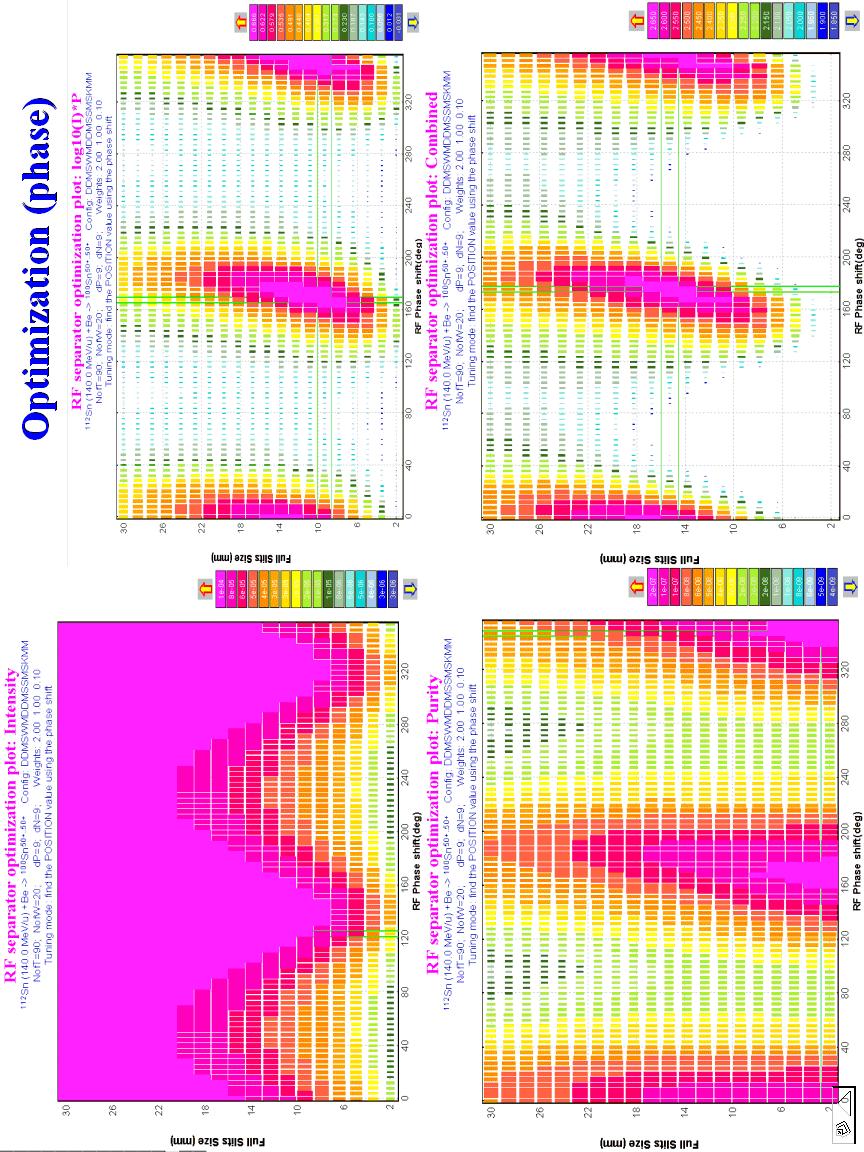
14 Fig.22. RIKEN RF kicker separation. Bottom plots demonstrate RIKEN experimental data [Yam04] and top plots show LISE calculations Intensity and purity optimization utility Fig.23. The RF kicker optimization dialog

15 - 15 -
16 - 16 -

 to")
 1.6.2.")
 without")
17 1.6. RF kicker productivity at NSCL Optimization (target & wedge) to produce 100 Sn (60MeV/u) Purification for 100 Sn(60MeV/u) without charge states


18 Purification for 100 Sn(60MeV/u) with charge states


19 Low frequency Purification ~ It is possible also to solve this problem with: * Increase the fragment energy * Decrease the length of flight Short flight base (35 m) Purification ~

 Purification")
20 High energy (105 MeV/u) Purification ~ Short flight base (35 m), High energy (105 MeV/u) Purification ~
21 Acknowledgements The LISE++ authors thank Dr. Marc Doleans for help in developing the RF kicker block in the code. References: [RFS05] RF kicker proposal, V. Andreev, D.Bazin, M. Doleans, D.Gorelov, F. Marti, X. Wu; RF-KICKER SYSTEM FOR SECONDARY BEAMS AT THE NSCL, D. Gorelov, V. Andreev, D. Bazin, M. Doleans, T. Grimm, F. Marti, J. Vincent, X. Wu, Proceedings of 2005 Particle Accelerator Conference, Knoxville, Tennessee; [Yam04] K.Yamada et al., Nuclear Physics A746 (2004) 156c-160c
Fragment Mass Analyzer Argonne N.L.
 Fragment Mass Analyzer (FMA) @ Argonne N.L. Version 9.10.177 from 09/11/2015 Link: Separator FMA @ ANL FMA extended configuration Documentation FMA files location Optics Optimization Angular Acceptance
Lattice Design for PRISM-FFAG. A. Sato Osaka University for the PRISM working group
 Lattice Design for PRISM-FFAG A. Sato Osaka University for the PRISM working group contents PRISM overview PRISM-FFAG dynamics study & its method PRISM Phase Rotated Intense Slow Muon source Anticipated
Present and future beams for SHE research at GSI W. Barth, GSI - Darmstadt
 Present and future beams for SHE research at GSI W. Barth, GSI - Darmstadt 1. Heavy Ion Linear Accelerator UNILAC 2. GSI Accelerator Facility Injector for FAIR 3. Status Quo of the UNILAC-performance 4.
Proton beam for UCN. UCN TAC-Meeting, May 12-13, 2005 Urs Rohrer, beam line physicist
 Proton beam for UCN UCN TAC-Meeting, May 12-13, 2005 Urs Rohrer, beam line physicist PSI Accelerator Division Department of Large Research Facilities Introduction Important parameters of the PSI proton
OPTIMIZED MAGNET FOR A 250 MEV PROTON RADIOTHERAPY CYCLOTRON
 OPTIMIZED MAGNET FOR A 250 MEV PROTON RADIOTHERAPY CYCLOTRON J. Kim and H. Blosser 1. Introduction The design of a K250 superconducting cyclotron has been recently improved from the original design of
New Tracking Gantry-Synchrotron Idea. G H Rees, ASTeC, RAL, U.K,
 New Tracking Gantry-Synchrotron Idea G H Rees, ASTeC, RAL, U.K, Scheme makes use of the following: simple synchrotron and gantry magnet lattices series connection of magnets for 5 Hz tracking one main
ReA3 Marc Doleans (On behalf of the ReA3 team)
") ReA3 Marc Doleans (On behalf of the ReA3 team) HIAT09, 08/06/2009, Slide 1 Building addition Office building (~100 staff + conf. rooms) ReA3 Experimental area 9100 sqft HIAT09, 08/06/2009, Slide 2 Why
ReA3 Marc Doleans (On behalf of the ReA3 team) HIAT09, 08/06/2009, Slide 1 Building addition Office building (~100 staff + conf. rooms) ReA3 Experimental area 9100 sqft HIAT09, 08/06/2009, Slide 2 Why
RF Time Measuring Technique With Picosecond Resolution and Its Possible Applications at JLab. A. Margaryan
 RF Time Measuring Technique With Picosecond Resolution and Its Possible Applications at JLab A. Margaryan 1 Contents Introduction RF time measuring technique: Principles and experimental results of recent
Polarization Experiments Using Jones Calculus
 Polarization Experiments Using Jones Calculus Reference http://chaos.swarthmore.edu/courses/physics50_2008/p50_optics/04_polariz_matrices.pdf Theory In Jones calculus, the polarization state of light is
Physics 132 Quiz # 23
 Name (please (please print) print) Physics 132 Quiz # 23 I. I. The The current in in an an ac ac circuit is is represented by by a phasor.the value of of the the current at at some time time t t is is
TECHNIQUE AND INSTRUMENTATION FOR BUNCH SHAPE MEASUREMENTS
 TECHNIQUE AND INSTRUMENTATION FOR BUNCH SHAPE MEASUREMENTS A.Feschenko Institute For Nuclear Research (INR), Moscow 3, Russia ),,, ( ),,, ( t z y x t y x ρ ϕ ρ Z,ϕ Y X ),,, ( t y x ϕ ρ dxd y t y x t J
Low-beta Structures. Maurizio Vretenar CERN BE/RF CAS RF Ebeltoft 2010
 Low-beta Structures Maurizio Vretenar CERN BE/RF CAS RF Ebeltoft. Low-beta: problems and solutions. Coupled-cell accelerating structures 3. Overview and comparison of low-beta structures 4. The Radio Frequency
Accelerator Complex U70 of IHEP-Protvino: Status and Upgrade Plans
 INSTITUTE FOR HIGH ENERGY PHYSICS () Protvino, Moscow Region, 142281, Russia Accelerator Complex U70 of -Protvino: Status and Upgrade Plans (report 4.1-1) Sergey Ivanov, on behalf of the U70 staff September
A HIGH EFFICIENCY 17GHz TW CHOPPERTRON
 1 SLAC 07 A HIGH EFFICIENCY 17GHz TW CHOPPERTRON J. Haimson and B. Mecklenburg Work performed under the auspices of the U.S. Department of Energy SBIR Grant No.DE-FG02-06ER84468 2 SLAC 07 Figure 1. Centerline
Lawrence Berkeley Laboratory UNIVERSITY OF CALIFORNIA
 d e Lawrence Berkeley Laboratory UNIVERSITY OF CALIFORNIA Accelerator & Fusion Research Division I # RECEIVED Presented at the International Workshop on Collective Effects and Impedance for B-Factories,
S800 Spectrograph Service Level Description
 I.Standard Configuration A. General The S800 is a large acceptance, high-resolution spectrograph designed for experiments using radioactive beams produced by projectile fragmentation. It is composed of
Analysis of Phase Space Matching with RF Quadrupole
 Analysis of Phase Space Matching with RF Quadrupole D.L.Rubin December 2, 21 1 Introduction Young-Im Kim, Seung Pyo Chang, Martin Gaisser, Uiryeol Lee, Soohyung Lee, and Yannis Semertzidis propose to superimpose
JEDI. Status of the commissioning of the waveguide RF Wien Filter
 COSY Beam Time Request For Lab. use Exp. No.: Session No. E 005.4 7 Collaboration: JEDI Status of the commissioning of the waveguide RF Wien Filter Spokespersons for the beam time: Ralf Gebel (Jülich)
EMMA the World's First Non-Scaling FFAG Accelerator
 EMMA the World's First Non-Scaling FFAG Accelerator Susan Smith STFC Daresbury Laboratory CONTENTS Introduction Contents What are ns-ffags? and Why EMMA? The international collaboration EMMA goals and
FAST RF KICKER DESIGN
 FAST RF KICKER DESIGN David Alesini LNF-INFN, Frascati, Rome, Italy ICFA Mini-Workshop on Deflecting/Crabbing Cavity Applications in Accelerators, Shanghai, April 23-25, 2008 FAST STRIPLINE INJECTION KICKERS
LHC TRANSVERSE FEEDBACK SYSTEM: FIRST RESULTS OF COMMISSIONING. V.M. Zhabitsky XXI Russian Particle Accelerator Conference
 LHC TRANSVERSE FEEDBACK SYSTEM: FIRST RESULTS OF COMMISSIONING V.M. Zhabitsky XXI Russian Particle Accelerator Conference 28.09-03.10.2008, Zvenigorod LHC Transverse Feedback System: First Results of Commissioning
S.M. Lidia, G. Bazouin, P.A. Seidl Accelerator and Fusion Research Division Lawrence Berkeley National Laboratory Berkeley, CA USA
 S.M. Lidia, G. Bazouin, P.A. Seidl Accelerator and Fusion Research Division Lawrence Berkeley National Laboratory Berkeley, CA USA The Heavy Ion Fusion Sciences Virtual National Laboratory 1 NDCX Increased
CERN EUROPEAN ORGANIZATION FOR NUCLEAR RESEARCH INVESTIGATION OF A RIDGE-LOADED WAVEGUIDE STRUCTURE FOR CLIC X-BAND CRAB CAVITY
 CERN EUROPEAN ORGANIZATION FOR NUCLEAR RESEARCH CLIC Note 1003 INVESTIGATION OF A RIDGE-LOADED WAVEGUIDE STRUCTURE FOR CLIC X-BAND CRAB CAVITY V.F. Khan, R. Calaga and A. Grudiev CERN, Geneva, Switzerland.
arxiv: v1 [physics.ins-det] 25 Oct 2012
![arxiv: v1 [physics.ins-det] 25 Oct 2012](/thumbs/93/113010072.jpg "arxiv: v1 [physics.ins-det] 25 Oct 2012") The RPC-based proposal for the ATLAS forward muon trigger upgrade in view of super-lhc arxiv:1210.6728v1 [physics.ins-det] 25 Oct 2012 University of Michigan, Ann Arbor, MI, 48109 On behalf of the ATLAS
The RPC-based proposal for the ATLAS forward muon trigger upgrade in view of super-lhc arxiv:1210.6728v1 [physics.ins-det] 25 Oct 2012 University of Michigan, Ann Arbor, MI, 48109 On behalf of the ATLAS
S800 Spectrograph Service Level Description
 I. Standard Configuration A. General The S800 is a large acceptance, high-resolution spectrograph designed for experiments using radioactive beams produced by projectile fragmentation. It is composed of
DESIGN AND BEAM DYNAMICS STUDIES OF A MULTI-ION LINAC INJECTOR FOR THE JLEIC ION COMPLEX
 DESIGN AND BEAM DYNAMICS STUDIES OF A MULTI-ION LINAC INJECTOR FOR THE JLEIC ION COMPLEX Speaker: P.N. Ostroumov Contributors: A. Plastun, B. Mustapha and Z. Conway HB2016, July 7, 2016, Malmö, Sweden
PArticles in an accelerator generally oscillate in directions
 1 Real-Time Betatron Tune Correction with the Precise Measurement of Magnet Current Yoshinori Kurimoto, Tetsushi Shimogawa and Daichi Naito arxiv:1806.04022v1 [physics.acc-ph] 11 Jun 2018 Abstract The
Notes on the VPPEM electron optics
 Notes on the VPPEM electron optics Raymond Browning 2/9/2015 We are interested in creating some rules of thumb for designing the VPPEM instrument in terms of the interaction between the field of view at
9. Microwaves. 9.1 Introduction. Safety consideration
 MW 9. Microwaves 9.1 Introduction Electromagnetic waves with wavelengths of the order of 1 mm to 1 m, or equivalently, with frequencies from 0.3 GHz to 0.3 THz, are commonly known as microwaves, sometimes
The design of a radio frequency quadrupole LINAC for the RIB project at VECC Kolkata
 PRAMANA cfl Indian Academy of Sciences Vol. 59, No. 6 journal of December 2002 physics pp. 957 962 The design of a radio frequency quadrupole LINAC for the RIB project at VECC Kolkata V BANERJEE 1;Λ, ALOK
Theoretical Study to calculate some parameters of Ion Optical System
 International Journal of ChemTech Research CODEN (USA): IJCRGG, ISSN: 97-9, ISSN(Online):55-9555 Vol.1 No.13, pp 1-18, 17 Theoretical Study to calculate some parameters of Ion Optical System *Bushra Joudah
DEVELOPMENT OF CAPACITIVE LINEAR-CUT BEAM POSITION MONITOR FOR HEAVY-ION SYNCHROTRON OF KHIMA PROJECT
 DEVELOPMENT OF CAPACITIVE LINEAR-CUT BEAM POSITION MONITOR FOR HEAVY-ION SYNCHROTRON OF KHIMA PROJECT Ji-Gwang Hwang, Tae-Keun Yang, Seon Yeong Noh Korea Institute of Radiological and Medical Sciences,
COMMISSIONING AND INITIAL OPERATING EXPERIENCE WITH THE SNS 1 GEV LINAC*
 COMMISSIONING AND INITIAL OPERATING EXPERIENCE WITH THE SNS 1 GEV LINAC* Stuart Henderson, Spallation Neutron Source, Oak Ridge National Laboratory, Oak Ridge TN, USA Abstract The Spallation Neutron Source
Detector Checkout and Optics Commissioning
 Detector Checkout and Optics Commissioning Jure Bericic Brad Sawatzky with SHMS optics working group Hall C Winter Collaboration Meeting January 20, 2017 overview HMS overview SHMS overview commissioning
ALIGNMENT METHODS APPLIED TO THE LEP MAGNET MEASUREMENTS. J. Billan, G. Brun, K. N. Henrichsen, P. Legrand, 0. Pagano, P. Rohmig and L. Walckiers.
 295 ALIGNMENT METHODS APPLIED TO THE LEP MAGNET MEASUREMENTS J. Billan, G. Brun, K. N. Henrichsen, P. Legrand, 0. Pagano, P. Rohmig and L. Walckiers. CERN, CH-1211 Geneva 23, Switzerland Introduction Electromagnets
REVIEW OF FAST BEAM CHOPPING F. Caspers CERN AB-RF-FB
 F. Caspers CERN AB-RF-FB Introduction Review of several fast chopping systems ESS-RAL LANL-SNS JAERI CERN-SPL Discussion Conclusion 1 Introduction Beam choppers are typically used for β = v/c values between
Non-invasive Beam Profile Measurements using an Electron-Beam Scanner
 Non-invasive Beam Profile Measurements using an Electron-Beam Scanner W. Blokland and S. Cousineau Willem Blokland for the Spallation Neutron Source Managed by UT-Battelle Overview SNS Accelerator Electron
3 General layout of the XFEL Facility
 3 General layout of the XFEL Facility 3.1 Introduction The present chapter provides an overview of the whole European X-Ray Free-Electron Laser (XFEL) Facility layout, enumerating its main components and
JUAS 2018 LINACS. Jean-Baptiste Lallement, Veliko Dimov BE/ABP CERN.
 LINACS Jean-Baptiste Lallement, Veliko Dimov BE/ABP CERN jean-baptiste.lallement@cern.ch http://jlalleme.web.cern.ch/jlalleme/juas2018/ Credits Much material is taken from: Thomas Wangler, RF linear accelerators
Design of ESS-Bilbao RFQ Linear Accelerator
 Design of ESS-Bilbao RFQ Linear Accelerator J.L. Muñoz 1*, D. de Cos 1, I. Madariaga 1 and I. Bustinduy 1 1 ESS-Bilbao *Corresponding author: Ugaldeguren III, Polígono A - 7 B, 48170 Zamudio SPAIN, jlmunoz@essbilbao.org
RCNP CYCLOTRON FACILITY
 RCNP CYCLOTRON FACILITY K. Hatanaka *, M. Fukuda, T. Yorita, T. Saito, H. Tamura, M. Kibayashi, S. Morinobu, K. Nagayama RCNP, Osaka University, 10-1 Mihogaoka, Ibaraki, Osaka 567-0047, Japan Abstract
Magnetism and Induction
 Magnetism and Induction Before the Lab Read the following sections of Giancoli to prepare for this lab: 27-2: Electric Currents Produce Magnetism 28-6: Biot-Savart Law EXAMPLE 28-10: Current Loop 29-1:
LINAC EXPERIENCE IN THE FIRST TWO YEARS OF CNAO (CENTRO NAZIONALE ADROTERAPIA ONCOLOGICA)
") LINAC EXPERIENCE IN THE FIRST TWO YEARS OF OPERATION @ CNAO (CENTRO NAZIONALE ADROTERAPIA ONCOLOGICA) S. Vitulli, E. Vacchieri, CNAO Foundation, Pavia, Italy A. Reiter, B. Schlitt, GSI, Darmstadt, Germany
LINAC EXPERIENCE IN THE FIRST TWO YEARS OF OPERATION @ CNAO (CENTRO NAZIONALE ADROTERAPIA ONCOLOGICA) S. Vitulli, E. Vacchieri, CNAO Foundation, Pavia, Italy A. Reiter, B. Schlitt, GSI, Darmstadt, Germany
WIEN Software for Design of Columns Containing Wien Filters and Multipole Lenses
 WIEN Software for Design of Columns Containing Wien Filters and Multipole Lenses An integrated workplace for analysing and optimising the column optics Base Package (WIEN) Handles round lenses, quadrupoles,
UNIT Explain the radiation from two-wire. Ans: Radiation from Two wire
 UNIT 1 1. Explain the radiation from two-wire. Radiation from Two wire Figure1.1.1 shows a voltage source connected two-wire transmission line which is further connected to an antenna. An electric field
SUPERCONDUCTING GANTRY AND OTHER DEVELOPMENTS AT HIMAC
 SUPERCONDUCTING GANTRY AND OTHER DEVELOPMENTS AT HIMAC Y. Iwata *, K. Noda, T. Shirai, T. Murakami, T. Fujita, T. Furukawa, K. Mizushima, Y. Hara, S. Suzuki, S. Sato, and K. Shouda, NIRS, 4-9-1 Anagawa,
BL39XU Magnetic Materials
 BL39XU Magnetic Materials BL39XU is an undulator beamline that is dedicated to hard X-ray spectroscopy and diffractometry requiring control of the X-ray polarization state. The major applications of the
LOS 1 LASER OPTICS SET
 LOS 1 LASER OPTICS SET Contents 1 Introduction 3 2 Light interference 5 2.1 Light interference on a thin glass plate 6 2.2 Michelson s interferometer 7 3 Light diffraction 13 3.1 Light diffraction on a
Particle Simulation of Radio Frequency Waves in Fusion Plasmas
 1 TH/P2-10 Particle Simulation of Radio Frequency Waves in Fusion Plasmas Animesh Kuley, 1 Jian Bao, 2,1 Zhixuan Wang, 1 Zhihong Lin, 1 Zhixin Lu, 3 and Frank Wessel 4 1 Department of Physics and Astronomy,
cyclotron RF systems sb/cas10061/1
 cyclotron RF systems sb/cas10061/1 outline cyclotron basics resonator design techniques transmission line 3D finite element tuning power coupling RF control flat topping some specific examples sb/cas100562
Lecture 5: Polarisation of light 2
 Lecture 5: Polarisation of light 2 Lecture aims to explain: 1. Circularly and elliptically polarised light 2. Optical retarders - Birefringence - Quarter-wave plate, half-wave plate Circularly and elliptically
FAST KICKERS LNF-INFN
 ILC Damping Rings R&D Workshop - ILCDR06 September 26-28, 2006 at Cornell University FAST KICKERS R&D @ LNF-INFN Fabio Marcellini for the LNF fast kickers study group* * D. Alesini, F. Marcellini P. Raimondi,
PHYS 241 FINAL EXAM December 11, 2006
 1. (5 points) Light of wavelength λ is normally incident on a diffraction grating, G. On the screen S, the central line is at P and the first order line is at Q, as shown. The distance between adjacent
DEVELOPMENT OF OFFNER RELAY OPTICAL SYSTEM FOR OTR MONITOR AT 3-50 BEAM TRANSPORT LINE OF J-PARC
 Proceedings of IBIC01, Tsukuba, Japan DEVELOPMENT OF OFFNER RELAY OPTICAL SYSTEM FOR OTR MONITOR AT 3-50 BEAM TRANSPORT LINE OF J-PARC M. Tejima #, Y. Hashimoto, T. Toyama, KEK/J-PARC, Tokai, Ibaraki,
Transverse Wakefields and Alignment of the LCLS-II Kicker and Septum Magnets
 Transverse Wakefields and Alignment of the LCLS-II Kicker and Septum Magnets LCLS-II TN-16-13 12/12/2016 P. Emma, J. Amann,K. Bane, Y. Nosochkov, M. Woodley December 12, 2016 LCLSII-TN-XXXX 1 Introduction
A Conceptual Tour of Pulsed NMR*
 A Conceptual Tour of Pulsed NMR* Many nuclei, but not all, possess both a magnetic moment, µ, and an angular momentum, L. Such particles are said to have spin. When the angular momentum and magnetic moment
Alternating current circuits- Series RLC circuits
 FISI30 Física Universitaria II Professor J.. ersosimo hapter 8 Alternating current circuits- Series circuits 8- Introduction A loop rotated in a magnetic field produces a sinusoidal voltage and current.
ION PRODUCTION AND RF GENERATION IN THE DARHT-II BEAM DUMP
 ION PRODUCTION AND RF GENERATION IN THE DARHT-II BEAM DUMP M. E. Schulze, C.A. Ekdahl Los Alamos National Laboratory, Los Alamos, NM 87545, USA T.P. Hughes, C. Thoma Voss Scientific LLC, Albuquerque, NM
Tutorial: designing a converging-beam electron gun and focusing solenoid with Trak and PerMag
 Tutorial: designing a converging-beam electron gun and focusing solenoid with Trak and PerMag Stanley Humphries, Copyright 2012 Field Precision PO Box 13595, Albuquerque, NM 87192 U.S.A. Telephone: +1-505-220-3975
Electromagnetic Induction - A
 Electromagnetic Induction - A APPARATUS 1. Two 225-turn coils 2. Table Galvanometer 3. Rheostat 4. Iron and aluminum rods 5. Large circular loop mounted on board 6. AC ammeter 7. Variac 8. Search coil
MEMS Optical Scanner "ECO SCAN" Application Notes. Ver.0
 MEMS Optical Scanner "ECO SCAN" Application Notes Ver.0 Micro Electro Mechanical Systems Promotion Dept., Visionary Business Center The Nippon Signal Co., Ltd. 1 Preface This document summarizes precautions
Suppression of Vertical Oscillation and Observation of Flux Improvement during Top-up Injection at PLS-II
 Suppression of Vertical Oscillation and Observation of Flux Improvement during Top-up Injection at PLS-II Y-G. Son, 1 J.-Y. Kim, 1 C. Mitsuda, 2 K. Kobayashi, 2 J. Ko, 1 T-Y. Lee, 1 J-Y. Choi, 1 D-E. Kim,
Measurements of Mode Converted ICRF Waves with Phase Contrast Imaging in Alcator C-Mod
 Measurements of Mode Converted ICRF Waves with Phase Contrast Imaging in Alcator C-Mod N. Tsujii, M. Porkolab, E.M. Edlund, L. Lin, Y. Lin, J.C. Wright, S.J. Wukitch MIT Plasma Science and Fusion Center
THE SINUSOIDAL WAVEFORM
 Chapter 11 THE SINUSOIDAL WAVEFORM The sinusoidal waveform or sine wave is the fundamental type of alternating current (ac) and alternating voltage. It is also referred to as a sinusoidal wave or, simply,
A Synchrotron Phase Detector for the Fermilab Booster
 FERMILAB-TM-2234 A Synchrotron Phase Detector for the Fermilab Booster Xi Yang and Rene Padilla Fermi National Accelerator Laboratory Box 5, Batavia IL 651 Abstract A synchrotron phase detector is diagnostic
University of TN Chattanooga Physics1040L 8/29/2012 PHYSICS 1040L LAB LAB 6: USE OF THE OSCILLOSCOPE
 PHYSICS 1040L LAB LAB 6: USE OF THE OSCILLOSCOPE Object: To become familiar with the operation of the oscilloscope and be able to use an oscilloscope for: 1. Measuring the frequency of an oscillator, 2.
Brett Parker, representing the
 Compact Superconducting Magnet Solution for the 20 mr Crossing Angle Final Focus Brett Parker, representing the Brookhaven Superconducting Magnet Division Message: Progress continues on the compact superconducting
Beam Position Monitoring System In Accelerators
 Beam Position Monitoring System In Accelerators Department of Electrical and Information Technology Lund University & European Spallation source Lund, Sweden Elham Vafa Rouhina Behpour Supervisors: Anders
LRC Circuit PHYS 296 Your name Lab section
 LRC Circuit PHYS 296 Your name Lab section PRE-LAB QUIZZES 1. What will we investigate in this lab? 2. Figure 1 on the following page shows an LRC circuit with the resistor of 1 Ω, the capacitor of 33
Precision RF Beam Position Monitors for Measuring Beam Position and Tilt Progress Report
 Precision RF Beam Position Monitors for Measuring Beam Position and Tilt Progress Report UC Berkeley Senior Personnel Yury G. Kolomensky Collaborating Institutions Stanford Linear Accelerator Center: Marc
Paul Scherrer Institute Pierre-André Duperrex. On-line calibration schemes for RF-based beam diagnostics
 Paul Scherrer Institute Pierre-André Duperrex On-line calibration schemes for RF-based beam diagnostics HB2012 Beijing, 17-20 Sept. 2012 Motivation Current monitor Some difficulties related to RF signal
PANalytical X pert Pro High Resolution Specular and Rocking Curve Scans User Manual (Version: )
") University of Minnesota College of Science and Engineering Characterization Facility PANalytical X pert Pro High Resolution Specular and Rocking Curve Scans User Manual (Version: 2012.10.17) The following
University of Minnesota College of Science and Engineering Characterization Facility PANalytical X pert Pro High Resolution Specular and Rocking Curve Scans User Manual (Version: 2012.10.17) The following
Calculation of Remanent Dose Rate Maps in the LHC Beam Dump Caverns
 EDMS Document Number: 784972 ORGANISATION EUROPENNE POUR LA RECHERCHE NUCLEAIRE EUROPEAN ORGANIZATION FOR NUCLEAR RESEARCH Laboratoire Européen pour la Physique des Particules European Laboratory for Particle
Coil in the AC circuit
 Coil in the AC circuit LEP Related topics Inductance, Kirchhoff s laws, parallel connection, series connection, a. c. impedance, phase displacement, vector diagram Principle The impedance and phase displacement
RF discharge at medium and high pressure & its possibilities for material surface modification
 RF discharge at medium and high pressure & its possibilities for material surface modification Approved tor Public ReleaseA.F.Aiexandrov, G.E. Bugrov, E.A. Kralkina, V.B. Pavlov, V. Plaksin, Distribution
ELECTRON BEAM DIAGNOSTICS AND FEEDBACK FOR THE LCLS-II*
 THB04 Proceedings of FEL2014, Basel, Switzerland ELECTRON BEAM DIAGNOSTICS AND FEEDBACK FOR THE LCLS-II* Josef Frisch, Paul Emma, Alan Fisher, Patrick Krejcik, Henrik Loos, Timothy Maxwell, Tor Raubenheimer,
Long Pulse Operation of a High Power Microwave Source with a Metamaterial Loaded Waveguide
 MURI Grad Student Teleseminar Long Pulse Operation of a High Power Microwave Source with a Metamaterial Loaded Waveguide Xueying Lu MIT 02/03/2016 Outline Review of Stage I experiment Jason Hummelt thesis
PHY3902 PHY3904. Nuclear magnetic resonance Laboratory Protocol
 PHY3902 PHY3904 Nuclear magnetic resonance Laboratory Protocol PHY3902 PHY3904 Nuclear magnetic resonance Laboratory Protocol GETTING STARTED You might be tempted now to put a sample in the probe and try
BEAM HALO OBSERVATION BY CORONAGRAPH
 BEAM HALO OBSERVATION BY CORONAGRAPH T. Mitsuhashi, KEK, TSUKUBA, Japan Abstract We have developed a coronagraph for the observation of the beam halo surrounding a beam. An opaque disk is set in the beam
AC Dispersion Measurement. David Rubin Cornell Laboratory for Accelerator-Based Sciences and Education
 AC Dispersion Measurement David Rubin Cornell Laboratory for Accelerator-Based Sciences and Education AC dispersion measurement Traditional dispersion measurement - Measure orbit - Change ring energy (δe/e
A novel solution for various monitoring applications at CERN
 A novel solution for various monitoring applications at CERN F. Lackner, P. H. Osanna 1, W. Riegler, H. Kopetz CERN, European Organisation for Nuclear Research, CH-1211 Geneva-23, Switzerland 1 Department
Trigger Rate Dependence and Gas Mixture of MRPC for the LEPS2 Experiment at SPring-8
 Trigger Rate Dependence and Gas Mixture of MRPC for the LEPS2 Experiment at SPring-8 1 Institite of Physics, Academia Sinica 128 Sec. 2, Academia Rd., Nankang, Taipei 11529, Taiwan cyhsieh0531@gmail.com
DOPPLER RADAR. Doppler Velocities - The Doppler shift. if φ 0 = 0, then φ = 4π. where
 Q: How does the radar get velocity information on the particles? DOPPLER RADAR Doppler Velocities - The Doppler shift Simple Example: Measures a Doppler shift - change in frequency of radiation due to
KULLIYYAH OF ENGINEERING
 KULLIYYAH OF ENGINEERING DEPARTMENT OF ELECTRICAL & COMPUTER ENGINEERING ANTENNA AND WAVE PROPAGATION LABORATORY (ECE 4103) EXPERIMENT NO 3 RADIATION PATTERN AND GAIN CHARACTERISTICS OF THE DISH (PARABOLIC)
Lab 12 Microwave Optics.
 b Lab 12 Microwave Optics. CAUTION: The output power of the microwave transmitter is well below standard safety levels. Nevertheless, do not look directly into the microwave horn at close range when the
K1200 Stripper Foil Mechanism RF Shielding
 R.F. Note #121 Sept. 21, 2000 John Vincent Shelly Alfredson John Bonofiglio John Brandon Dan Pedtke Guenter Stork K1200 Stripper Foil Mechanism RF Shielding INTRODUCTION... 2 MEASUREMENT TECHNIQUES AND
GSEB QUESTION PAPER PHYSICS
 GSEB QUESTION PAPER PHYSICS Time : 3 Hours Maximum Marks: 100 Instructions : 1. There are four sections and total 60 questions in this question paper. 2. Symbols used in this question paper have their
High acceleration gradient. Critical applications: Linear colliders e.g. ILC X-ray FELs e.g. DESY XFEL
 High acceleration gradient Critical applications: Linear colliders e.g. ILC X-ray FELs e.g. DESY XFEL Critical points The physical limitation of a SC resonator is given by the requirement that the RF magnetic
Beam Control: Timing, Protection, Database and Application Software
 Beam Control: Timing, Protection, Database and Application Software C.M. Chu, J. Tang 储中明 / 唐渊卿 Spallation Neutron Source Oak Ridge National Laboratory Outline Control software overview Timing system Protection
Recent Experimental Studies of the Electron Cloud at the Los Alamos PSR
 Recent Experimental Studies of the Electron Cloud at the Los Alamos PSR Robert Macek, 9/11/01 - KEK Workshop Co-authors: A. Browman, D. Fitzgerald, R. McCrady, T. Spickermann and T. S. Wang 1 Outline Background:
CEBAF Overview June 4, 2010
 CEBAF Overview June 4, 2010 Yan Wang Deputy Group Leader of the Operations Group Outline CEBAF Timeline Machine Overview Injector Linear Accelerators Recirculation Arcs Extraction Systems Beam Specifications
Applications of Monte Carlo Methods in Charged Particles Optics
 Sydney 13-17 February 2012 p. 1/3 Applications of Monte Carlo Methods in Charged Particles Optics Alla Shymanska alla.shymanska@aut.ac.nz School of Computing and Mathematical Sciences Auckland University
ANALYSIS OF 3RD OCTAVE BAND GROUND MOTIONS TRANSMISSION IN SYNCHROTRON RADIATION FACILITY SOLARIS Daniel Ziemianski, Marek Kozien
 ANALYSIS OF 3RD OCTAVE BAND GROUND MOTIONS TRANSMISSION IN SYNCHROTRON RADIATION FACILITY SOLARIS Daniel Ziemianski, Marek Kozien Cracow University of Technology, Institute of Applied Mechanics, al. Jana
Experiment 19. Microwave Optics 1
 Experiment 19 Microwave Optics 1 1. Introduction Optical phenomena may be studied at microwave frequencies. Using a three centimeter microwave wavelength transforms the scale of the experiment. Microns
5.1 Graphing Sine and Cosine Functions.notebook. Chapter 5: Trigonometric Functions and Graphs
 Chapter 5: Trigonometric Functions and Graphs 1 Chapter 5 5.1 Graphing Sine and Cosine Functions Pages 222 237 Complete the following table using your calculator. Round answers to the nearest tenth. 2
Beam Commissioning and Operation of New Linac Injector for RIKEN RI Beam Factory
 Beam Commissioning and Operation of New Linac Injector for RIKEN RI Beam Factory RIKEN Nishina Center Kazunari Yamada, K. Suda, S. Arai, M. Fujimaki, T. Fujinawa, H. Fujisawa, N. Fukunishi, Y. Higurashi,
Physics Requirements Document Document Title: SCRF 1.3 GHz Cryomodule Document Number: LCLSII-4.1-PR-0146-R0 Page 1 of 7
 Document Number: LCLSII-4.1-PR-0146-R0 Page 1 of 7 Document Approval: Originator: Tor Raubenheimer, Physics Support Lead Date Approved Approver: Marc Ross, Cryogenic System Manager Approver: Jose Chan,
Chapter 21. Alternating Current Circuits and Electromagnetic Waves
 Chapter 21 Alternating Current Circuits and Electromagnetic Waves AC Circuit An AC circuit consists of a combination of circuit elements and an AC generator or source The output of an AC generator is sinusoidal
Circumference 187 m (bending radius = 8.66 m)
") 4. Specifications of the Accelerators Table 1. General parameters of the PF storage ring. Energy 2.5 GeV (max 3.0 GeV) Initial stored current multi-bunch 450 ma (max 500 ma at 2.5GeV) single bunch 70 ma
4. Specifications of the Accelerators Table 1. General parameters of the PF storage ring. Energy 2.5 GeV (max 3.0 GeV) Initial stored current multi-bunch 450 ma (max 500 ma at 2.5GeV) single bunch 70 ma
FLASH at DESY. FLASH. Free-Electron Laser in Hamburg. The first soft X-ray FEL operating two undulator beamlines simultaneously
 FLASH at DESY The first soft X-ray FEL operating two undulator beamlines simultaneously Katja Honkavaara, DESY for the FLASH team FEL Conference 2014, Basel 25-29 August, 2014 First Lasing FLASH2 > First