INTRODUCTION TO RADIOFREQUENCY SYSTEMS FOR PARTICLE ACCELERATORS
|
|
|
- Oliver West
- 5 years ago
- Views:
Transcription
1
2 INTRODUCTION TO RADIOFREQUENCY SYSTEMS FOR PARTICLE ACCELERATORS Elettra-Sincrotrone Trieste S.C.p.A, Italy 39 th International Nathiagali Summer College 4 th 9 th August
3 OVERVIEW Introduction Building blocks Accelerating structures Power sources Power transmission LLRF Summary References and Bibliography 3
4 INTRODUCTION Historical Background and Tasks of the RF Systems 4
 Now replaced by radio-frequency quadrupoles.")

5 HISTORICAL BACKGROUND DC ACCELERATORS Tens of kv for x-ray tubes are easily produced by transformer rectifier power supplies Cockroft-Walton (1932 used for first accelerator experiments with protons) Based on the principle of charging capacitors and discharging them in series Used later as pre-accelerator for proton machines (typically up to 750 KV) Now replaced by radio-frequency quadrupoles. Van de Graaff generator It is an electrostatic machine which uses a moving belt to accumulate very high voltages on a hollow metal globe. Ion source is located inside the high voltage terminal and ions are accelerated by the electric voltage between the high-voltage supply and ground. Typical range around 15 MeV. Energy gain can be doubled with the tandem principle National Science Museum, London UK Energy gain in DC accelerators limited by the max potential difference that can be held 5
6 HISTORICAL BACKGROUND DC ACCELERATORS Limitation of DC accelerators can be overcome using time varying electromagnetic field. Resonant acceleration by means of time-varying fields across the drift tubes proposed by Ising (1924) This lead to the development of the first proof of principle linear accelerator by Wideroe (1927). First cyclotron was built in 1931 From these developments RF becomes the centre of particle accelerators. Following technological developments allowed to extend these ideas. 6
 and beam dynamics motivations (synchronization with the revolution frequencies of the particle in synchrotrons and cyclotrons) they have been")
7 BASIC DEFINITIONS In a particle accelerator the RADIOFREQUENCY SYSTEM is the part of the machine which is devoted to the generation of the accelerating E-field. Due to technical reasons (availability of power sources) and beam dynamics motivations (synchronization with the revolution frequencies of the particle in synchrotrons and cyclotrons) they have been developed mainly in the radio wave region of the e-m spectrum. 7
8 TASKS OF THE RF SYSTEM Accelerate the beam to higher energy Ex. Linacs, synchrotrons Compensate the losses due to synchrotron radiation Ex. Electron storage rings Provide a stable energy bucket to ensure a long lifetime 8
9 TASKS OF THE RF SYSTEM Accelerate the beam to higher energy LINAC FERMI linac: the electron beam is accelerated up to 1.5 GeV ESS linac; the proton beam will be accelerated to 2 GeV. SYNCHROTRONS Elettra booster: the electron beam is accelerated from 100 MeV to 2.4 GeV In SPS protons are accelerated up to 450 GeV,then in LHC they reach 4 TeV (per beam). CYCLOTRONS In the PSI ring cyclotron protons reach 590 MeV... 9
10 TASKS OF THE RF SYSTEM Compensate the losses du to synchrotron radiation Electromagnetic radiation is emitted by charged particles when accelerated in a curved path. For a bending magnet: Uo = 88.5 E 4 /ρ EXAMPLE- Elettra light source t 2 GeV Energy loss due to the bending magnet is kev/turn. To this we should add the losses in the insertion devices, which amount to kev/turn For a 330 ma beam this means 121 kw Without RF the beam is lost in less than 2 msec. The RF system must provide the power for the energy loss, otherwise the beam is rapidly lost 10

11 TASKS OF THE RF SYSTEM Provide a stable energy bucket to ensure a long lifetime RF acceptance is defined as the maximum energy deviation for which the synchrotron oscillation remains stable To ensure stability of longitudinal stability we need some overvoltage factor; q=v cav/ /U losses 11
12 BUILDING BLOCKS 12

13 BUILDING BLOCKS CAVITY This is where interaction with the beam takes place. Accelerates the beam Losses recovery Travelling or standing wave Single or multicell Normal or superconducting 13
14 BUILDING BLOCKS POWER SOURCE Amplification of the driving signal to high level Tubes, solid state POWER TRANSMISSION Transports RF power Waveguide, coaxial Special components (circulators, directional couplers, loads, etc.) 14
15 BUILDING BLOCKS SIGNAL GENERATOR synthesized oscillators VCOs Laser to voltage converters LOW LEVEL RF (LLRF) Amplitude and phase setting Amplitude and phase stabilization Tuning control Beam loading compensation Feedbacks 15
16 PRACTICAL POINTS RF FREQUENCY RF frequencies in use in RF accelerators span from tens of MHz to tens of GHz Depends on machine type and requirements Depends on availability of sources DUTY CYCLE RF system can operate continuously (also called CW=continuous wave), or pulsed POWER LEVELS Powers sources up up to ~ 2 MW rms and ~ 100 MW pulsed TECHNOLOGIES Electromagnetism High voltage Vacuum Cooling Superconductivity Cryogenics Material science. 16
17 ACCELERATING STRUCTURES 17
18 ACCELERATING GAP An accelerating gap is the volume between two metallic (good conductors) tubes with the same axis. If the tubes are connected to a dc voltage, the field is as indicated. A negative particle coming from the negative electrode gains energy passing through the gap. - + If we assemble many gap in series and excite them properly with an AC voltage generator we obtain an electromagnetic linac (WIDEROE) 18

19 DRIFT TUBE Beam is accelerated when crossing the gap drift tubes If a particle that transit the gap has to be accelerated, the drift tube length is related to the particle velocity by the synchronism condition: Clearly as the velocity increases the drift tube become inconveniently long, unless the frequency can be increased. But: at high frequency an open drift tube structure become very lossy The natural evolution of the drift tubes was represented by high frequency, field distribute structures like resonant cavities or disk loaded waveguides. 19

 Voltage gain for a particle crossing the gap of")


20 THE TRANSIT TIME EFFECT A charged particle passing through a gap experiences a field that changes with time and position Field seen by the particle when crossing the reference plane (Note we assumed uniform field along the gap) Voltage gain for a particle crossing the gap of length g If the energy gain is small with respect to the energy of the particle, we can assume: z=v p t, where v p is the average speed of the particle and we have: The transit time factor is the reduction factor that takes into account the fact that the particle crosses the gap in a finite time 20


21 MAXWELL EQUATIONS 21
22 RESONANT CAVITY Closed volume where the e.m. fields can only exists in the form of particular spatial conformations (resonant modes) rigidly oscillating at some characteristic frequencies.(standing wave resonators). The resonant cavity modes are the solutions of the Maxwell equations inside closed volumes surrounded by perfectly conducting walls. The solution is represented by a discrete set of eigenfunctions and their associated eigenvalues k n = ω n /c The magnetic field eigenfunctions can be obtained form the Maxwell 3 rd equation. The functions are the cavity modes, each one resonating at a specific frequency ω n. 22
23 RESONANT CAVITY The eigenfunctions are a linear independent base, so the actual fields can be always be represented by a linear superposition of the cavity modes. The definition of the modes is generally TM mnp or E mnp modes: magnetic field only in transverse direction TE mnp or H mnp modes: electric field only in transverse direction In cylindrical coordinates: m = number of full-period variation of the fields components in the azimuthal direction n = number of zero-crossing of the longitudinal field components in the radial direction p = number of half-period variations of the fields components in the longitudinal direction 23

24 PILL BOX CAVITY Cylindrical empty volume limited by perfect conducting walls Assumption ρ = J = 0 inside the volume The Maxwell equation can be solved in cylindrical coordinates. The simplest solution is the TM 010 mode: Longitudinal electric field and transverse magnetic fields No field dependence on z and φ Frequency is only determined by the radius. 24


25 PILL BOX CAVITY Picture from G. Burt., Introduction to RF for Particle Accelerators, Lancaster University If one makes a hole on each side of the cavity, then particles can travel along the cavity and be accelerated. However real geometries adopted differ from the pill-box case: To increase accelerating efficiency one can introduce nose cones, as in many normal conducting cavities Geometry are smoothed (bell-shape) to avoid multipacting as in sc cavities or in the Elettra type nc cavity. Frequency and modes are calculated by means of e.m. simulation codes (SuperFISH, CST microwave, HFSS, ) 25
26 REAL CAVITY From ideal to real cavities we have to taken into account: The mechanical boundaries of the cavities are non-perfect conductors and (eventually) non perfect dielectrics. The continuity of the mechanical boundary is interrupted by the holes that are needed for coupling and monitoring. These perturbations introduce losses, so that a certain amount of power should be introduced inside the cavity to keep the field at the the desired level. If this is not done cavity field would decay exponentially. CAVITY EQUIVALENT CIRCUIT Picture from E.Jensen., RF Cavity Design, CAS, Chios A single mode of a resonant cavity can be represented as a simple RLC circuit In fact equivalent circuits have been proven to accurately model couplers, cavity coupling, microphonics, beam loading and field amplitudes in multicell cavities. These simple circuit equations can now be used to calculate the cavity parameters 26
27 FIGURES OF MERIT From A. Gallo, RF Systems, CAS, Varna
28 NORMAL CONDUCTING SUPERCONDUCTING Cavities can be wither normal conducting or superconduting. Choice depends on the specific application. Although there is no a definitive rule for the choice, in general: Normal conducting Less infrastructure Simpler technology Simpler tuning Higher RF power needs Thermal problems Lower gradients (i.e. more cavities needed for the same total voltage). Super conducting No thermal problems Less RF power, but do not forget the cryogenics Larger aperture Multipacting Cryogenic system required Complicated cavity fabrication Sensitive cavities 28


29 SINGLE CELL MULTICELL To increase acceleration efficiency, coupled structures can be used. But also in this case there is no universal recipe and the choice depends on the application, for example dangerous HOMs can be more easily damped in single cell cavities. Phase relation between the gap is important: 0,, π/2,π modes, following the phase advance per cell of the waveguide modes Elettra cavity Petra cavity 29

: The magnetic field of the mode we want")

: the inner")


30 COUPLING INPUT POWER COUPLERS: to feed the cavity with RF power RF PICK-UPs: to probe the field inside TYPE OF COUPLING MAGNETIC: (LOOPS): The magnetic field of the mode we want to excite in the cavity has a component in common with a loop connecting the inner and outer conuctors of a transmission line. ELECTRIC COUPLING (ANTENNAS): the inner conductor of a coaxial lines couples with the electric field of the mode of the cavity. WAVEGUIDE: the cavity fields are coupled to an external waveguide through a hole or a slot in the cavity walls. ALS Elettra cavity 30


31 TUNING Cavity resonant frequencies are affected by different reasons, for example by thermal drifts in normal conducting cavities or by pressure variations in the cryogenic bath in the superconducting case. Cavity should be kept at the required frequency during operation. Cavity frequency control is normally obtained by means of small deformations of the cavity volume. SLATER THEOREM PRACTICAL TUNING MECHANISMS Deformation by pushing/stretching by application of axial forces Plungers Cooling fluid temperatures 31
32 HOM Higher order modes (HOM) can be excited in the cavity by the beam passing into it. HOM can be detrimental to the stability of the beam and should be avoided. Some techniques: Temperature tuning in nc cavities (es. Elettra cavities). Dedicated HOM suppressors. Waveguide dampers (es. PEPII, ALBA) Beampipe dampers Longitudinal and transverse feedbacks.. 32


33 CYLINDRICAL WAVEGUIDE Uniform waveguide: a dielectric volume limited by conducting cylindrical walls For this case we can solve the Maxwell equations in cylindrical coordinates The simplest solutions with an axial electric field is the TM 01 mode, which has radial and longitudinal electric field and azimuthal magnetic field components. 33


34 CYLINDRICAL WAVEGUIDE Brillouin diagram for cylindrical waveguide Each frequency correspond to a certain phase velocity Propagation in a waveguide is always possible above the cut-off frequency The phase velocity is always higher than the speed of light It is impossible to accelerate particle in a cylindrical waveguide because synchronism between particle and RF is impossible NB. Information and energy travels at the group velocity v gr =dω/dk z and is always lower than c. 34


35 TRAVELLING WAVE STRUCTURE SOLUTION: Corrugated waveguide Travelling wave structure From F. Gerick Modes with phase velocity below c exist 35
36 WAVEGUIDE MODES Operation mode is defined as the phase difference between adjacent cells From G. Hoffstattetter, USPAS 2010, 36
37 EXAMPLES OF TYPES OF CAVITIES CONSTANT VELOCITY, CONSTANT FREQUENCY Relativistic particles Synchrotrons, linacs Electrons from MeV, protons above several GeV CHANGING VELOCITY, CONSTANT FREQUENCY Cyclotrons and low beta ion and proton linacs CHANGING VELOCITY, CHANGING FREQUENCY Low beta synchrotrons Ferrite cavities NON ACCELERATING CAVITIES RF Deflectors RF bpm 37
. Now adopted at SESAME.")

38 ELETTRA CAVITY Developed for Elettra Used in many synchrotron light sources (Campinas, ANKA, SLS, INDUSII). Now adopted at SESAME. Frequency 500 Mhz Accelerating voltage (Transit time corrected) 650 kv Power losses in copper Shunt impedance Nominal forward power matched 66 kw 3.2 MΩ 100 kw 38


39 SINGLE CELL CAVITIES PEP-II -476 MHz ALBA-500 MHZ MAX IV -100 MHZ 39


40 MULTICELL CAVITIES LEP 5 cells Normal conducting + storage cavity PETRA 5- cells 40


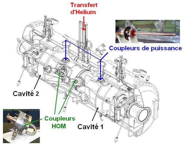

41 SUPERCONDUCTING CAVITIES Cornell 500 MHz Soleil 352 MHz 41


42 SUPERCONDUCTING CAVITIES LHC 400 MHz TESLA 1.3 GHZ LEP superconducting 352 Mhz 42

43 TW STRUCTURES Mode Type Frequency Eff. length 2π/3 TW on axis coupled Const. grad MHz m Q Rs Filling time 65 MΩ/m µsec Mode Type Frequency Eff. length 3π/4 BTW magnet. coupled Const. grad MHz m Q Rs Filling time MΩ/m µsec S-band LIL sections in the FERMI linac S-band BTWsections in the FERMI linac 43

 Cavity BPM")

 44")
44 OTHER EXAMPLES 3 rd harmonic cavity (Elettra, PSI) Cavity BPM (FERMI) High energy deflector (FERMI) Low energy deflector (FERMI) 44
45 MAKING IT WORK RF cavities operate at high e.m. fields and under UHV. The construction and operation require skills on different technology aspects Mechanical (machining, brazing, etc) Material science (high purity materials are needed) Vacuum (cavities operate at UHV, need pumping, bake-out) Cooling to remove the wasted power on the surface and keep the operating temperature stable. Cryogenics in case of sc cavities High field operation requires RF conditioning procedures which allows to reach and establish the required operating values in safe operation without breakdowns. 45
46 POWER SOURCES MUCH MORE IN THE RF POWER GENERATION AND TRANSMISSION FOR PARTICLE ACCELERATORS LECTURE 46
47 GENERAL POWER SOURCES High power RF is needed is needed for particle accelerators Typical frequency ranges span for tens of MHZ to tens of GHz or higher. Power requirements varies from few kw to few MW in cw (continuous wave) mode operation to up to 150 MW for pulsed sources. DEFINITION A power amplifier is the equipment which transforms d.c. electrical input power to RF power amplifying the driving signal provided by the low level RF electronics. If needed, power amplifier can be combined to achieve higher power. High power sources represent one of the main capital costs both in construction and in operations. Important concepts: efficiency and gain Other important points: size, weight and maintenance costs. 47

48 TECHNOLOGY Vacuum tubes Tetrode Klystron IOT Magnetron TWT Solid state 48
) 300")
 45MW")
 Tetrode")
 80 kw cw")
49 EXAMPLES 60 kw cw 500 MHz klystron (E2v 2672BCD)) 300 kw cw 500 MHz klystron (Thales TH22161) 45MW pulsed s-band klystron (Thales TH2132A) Tetrode for cw and pulsed operation (Thales TH595) 80 kw cw 500MHz IOT (E2V 2130)) 49


50 EXAMPLES 60 kw cw 500MHz klystron based amplifier at Elettra 150 kw cw 500MHz combined IOTs based amplifier at Elettra 45 MW peak S-band klystron and modulator at FERMI Solid state amplifier towers at SOLEIL (352 MHZ) 50
51 POWER TRANSMISSION MUCH MORE IN THE RF POWER GENERATION AND TRANSMISSION FOR PARTICLE ACCELERATORS LECTURE 51
52 GENERAL POWER TRANSMISSION The power transmission system is the assembly of components that perform the tasks of transporting the RF power from the power source to the cavities. This is usually accomplished by a network of coaxial lines or rigid rectangular waveguides. The choice depends on the frequency and power levels involved. Coaxial lines No cut-off Higher attenuation Difficult to cool Typical ranges in use: frequency dc to 10 GHz, power rating example 1 MW at 200 MHz Waveguides Cut-off Lower attenuation Easier to cool Higher frequency Higher power Typical ranges in use: frequency 0.32 to 352 GHz, power rating example 150 MW peak at 310 MHz In addition to standard components, also special components are needed, like bends, directional couplers, circulators, loads, etc. 52


53 EXAMPLES Waveguides feeding the S-band FERMI linac Circulator, load and coaxial lines for the 500 MHZ Elettra plants 500 MHz waveguide circulator Swtichless combiner 53
54 LLRF 54
55 SCOPE The low level RF system (LLRF) has the purpose of generating the driving signal provided to the high power amplifier with the correct amplitude and phase. The scope is to compensate for different effects, such as: Ripple on high voltage supplies Non linearities Beam loading Drifts The LLRF has also the task to control the tuning of the resonant cavity. In addition it can perform diagnostic and monitoring tasks. A typical LLRF system is composed of a number of integrated loops that accomplished the required tasks. In the last decades technology adopted has shifted from analogue electronics to digital LLRF system based on FPGA. 55

 Compares RF cavity sample with the set level.")
56 TASKS TUNING LOOP Keeps the cavity tuned compensated for cavity thermal drifts and beam loading. Phase comparison of signals from the cavity and at the cavity input Error signal drives the tuner AMPLITUDE/PHASE LOOP Automatic control of amplitude and phase of the RF fields Beam loading compensation in storage rings Beam energy stabilization (linacs) Bunch timing stabilization (storage rings and linacs) Compares RF cavity sample with the set level. Error signals used to modulate the driving signal to power source 56
57 TASKS AMPLITUDE BALANCE LOOP To avoid an excessive unbalance of the voltage between the cells in multicell cavities. Ex. Applied to PETRA cavities: Amplitude ratio detector compares voltage in cells 2 and 4. Errors signals drives the tuners differentially to balance the cells voltage OTHERS Suppression of instabilities due to the interaction with the cavity accelerating mode in storage rings combination of feedback loops (beam phase loop, direct RF feedback loop,...) and/or beam feed-forward compensations. Tracking of the revolution frequency, RF phase jump and related controls at crossing of the transition energy (RF gymnastic). Controls of transient effects in pulsed regime or related to gaps in the filling Compensation of cable length variation due to drifts. 57
58 TECHNOLOGY Originally fully analog electronic systems Nowadays digital systems are generally adopted taking advantages of the huge potentiality of modern FPGAs (field programmable gate array), Advanced RF/analog technology is still essential for the success of a digital LLRF ( front ends, signal conditioning, clock, etc). Therefore a digital LLRF is actually a mixed-signal system. Competence in both digital and RF/analog electronics are required to develop a LLRF system. Some features that can be reached with a digital system: Higher precision Lower noise Flexibility (FPGA can be reprogrammed without the need of hardware changes) Possibility of better diagnostics. 58


59 EXAMPLE FERMI LLRF Specification on amplitude and phase stability: 0.1% and 0.1 at 3 GHz. All-digital system, specifically developed for FERMI. System developed in the frame of a collaboration agreement between Elettra - Sincrotrone Trieste and Lawrence Berkeley National Lab. Loops: amplitude, phase, cable calibration local oscillator phase drift and phase reference loop. SLED: phase reversal and phase modulation. Final processing board, specifically designed for FERMI, will allow further firmware developments (for example intra-pulse feedback, real time communications between LLRF units, etc. ). Installation is now completed for the main controllers Reference LO signal OCXO ADC/DAC CLK ADC Tune ctrl FPGA CLK Cavity ADC Kly Out Drive Out Frontend RF 3 GHz 99 MHz Analog Signals ADC DAC Digital Board LLRF Chassis Digital Signals Digital Processing FPGA 59
60 SUMMARY Radio Frequency Systems represent one of the major parts of any accelerator and a critical aspects to achieve the desired performance. Many technologies are involved. A good knowledge of beam physics is also involved. This lecture is just to give a taste of the many interesting aspects involved. Topics not covered include: Derivation of cavity modes form Maxwell Equations Computer simulation codes Interaction with the beam Robinson instabilities Longitudinal dynamics, Coupled bunch instabilities. 60
61 Thank you! 61
62 REFERENCES AND BIBLIOGRAPHY 1. J. D. Jackson, Classical Electrodynamics, 3rd Edition (Wiley, New York, 1998). 2. R. E. Collin, Foundations for Microwave Engineering (McGraw Hill, New York, 1992). 3. J.C. Slater, Microwave Electronics, Dover Pub. Inc., (1969). 4. S. Ramo, J. R. Winery, and T. Van Duzer, Fields and Waves in Communication Electronics, 3 rd ed. (Wiley, New York, 1994). 5. G. Do me, Basic RF theory, waveguides and cavities, CERN Accelerator School: RF Engineering for Particle Accelerators, Oxford, P. Bryant, A Brief Review and History of Accelerators, CAS General Accelerator Physics 1992, Jyvaskyla 7. M. Puglisi, Conventional CavIty Design, CAS General Accelerator Physics 1992, Jyvaskyla 8. F. Gerigk: RF Basics I and II, CAS 2011, Bilbao 9. A. Gallo, Rf System, CAS General Accelerator Physics 2010, Varna 10. M. Weiss, Introduction to RF Linear Acclerators, CAS General Accelerator Physics 1992, Jyvaskyla 11. A. Wolski, Synchrotron Light Machines, CAS General Accelerator Physics 2012, GranadaA. Gallo, Rf System, CAS General Accelerator Physics 2010, Varna 12. F. Burt, Introduction to RF for Accelerator, Lancaster University 13. F.Gerigk, Cavity Types, CAS RF School 2010, Ebeltoft, Denmark. 14. E. Jensen, Cavity Basics, CAS RF School 2010, Ebeltoft, Denmark. 15. G. Hoeffstaetter, USPAS CERN Accelerator Schools (CAS) Proceedings, 62
63
ELECTRON LINACS. Alessandro Fabris. Elettra-Sincrotrone Trieste S.C.p.A, Italy. 39 th International Nathiagali Summer College 4 th 9 th August 2014
 ELECTRON LINACS Elettra-Sincrotrone Trieste S.C.p.A, Italy 39 th International Nathiagali Summer College 4 th 9 th August 2014 2 OVERVIEW Introduction Travelling wave structures Standing wave structures
JUAS 2018 LINACS. Jean-Baptiste Lallement, Veliko Dimov BE/ABP CERN.
 LINACS Jean-Baptiste Lallement, Veliko Dimov BE/ABP CERN jean-baptiste.lallement@cern.ch http://jlalleme.web.cern.ch/jlalleme/juas2018/ Credits Much material is taken from: Thomas Wangler, RF linear accelerators
Detailed Design Report
 Detailed Design Report Chapter 2 MAX IV 3 GeV Storage Ring 2.6. The Radio Frequency System MAX IV Facility CHAPTER 2.6. THE RADIO FREQUENCY SYSTEM 1(15) 2.6. The Radio Frequency System 2.6. The Radio Frequency
High acceleration gradient. Critical applications: Linear colliders e.g. ILC X-ray FELs e.g. DESY XFEL
 High acceleration gradient Critical applications: Linear colliders e.g. ILC X-ray FELs e.g. DESY XFEL Critical points The physical limitation of a SC resonator is given by the requirement that the RF magnetic
RF Cavity Design. Erk Jensen CERN BE/RF. CERN Accelerator School Accelerator Physics (Intermediate level) Darmstadt 2009
 Darmstadt 2009") RF Cavity Design Erk Jensen CERN BE/RF CERN Accelerator School Accelerator Physics (Intermediate level) Darmstadt 009 CAS Darmstadt '09 RF Cavity Design 1 Overview DC versus RF Basic equations: Lorentz
RF Cavity Design Erk Jensen CERN BE/RF CERN Accelerator School Accelerator Physics (Intermediate level) Darmstadt 009 CAS Darmstadt '09 RF Cavity Design 1 Overview DC versus RF Basic equations: Lorentz
Normal-conducting high-gradient rf systems
 Normal-conducting high-gradient rf systems Introduction Motivation for high gradient Order of 100 GeV/km Operational and state-of-the-art SwissFEL C-band linac: Just under 30 MV/m CLIC prototypes: Over
ACCELERATION TECHNIQUES
 ACCELERATION TECHNIQUES by Joël Le DuFF (LAL-Orsay) CAS on Intermediate Accelerator Physics Course Trieste 3-4 October 005 CAS, Trieste, October 3-4 005 Bibliography Alexander W. Chao & Maury Tigner :
REVIEW OF HIGH POWER CW COUPLERS FOR SC CAVITIES. S. Belomestnykh
 REVIEW OF HIGH POWER CW COUPLERS FOR SC CAVITIES S. Belomestnykh HPC workshop JLAB, 30 October 2002 Introduction Many aspects of the high-power coupler design, fabrication, preparation, conditioning, integration
04th - 16th August, th International Nathiagali Summer College 1 CAVITY BASICS. C. Serpico
 39th International Nathiagali Summer College 1 CAVITY BASICS C. Serpico 39th International Nathiagali Summer College 2 Outline Maxwell equations Guided propagation Rectangular waveguide Circular waveguide
Design of ESS-Bilbao RFQ Linear Accelerator
 Design of ESS-Bilbao RFQ Linear Accelerator J.L. Muñoz 1*, D. de Cos 1, I. Madariaga 1 and I. Bustinduy 1 1 ESS-Bilbao *Corresponding author: Ugaldeguren III, Polígono A - 7 B, 48170 Zamudio SPAIN, jlmunoz@essbilbao.org
Low-Level RF. S. Simrock, DESY. MAC mtg, May 05 Stefan Simrock DESY
 Low-Level RF S. Simrock, DESY Outline Scope of LLRF System Work Breakdown for XFEL LLRF Design for the VUV-FEL Cost, Personpower and Schedule RF Systems for XFEL RF Gun Injector 3rd harmonic cavity Main
MEASURES TO REDUCE THE IMPEDANCE OF PARASITIC RESONANT MODES IN THE DAΦNE VACUUM CHAMBER
 Frascati Physics Series Vol. X (1998), pp. 371-378 14 th Advanced ICFA Beam Dynamics Workshop, Frascati, Oct. 20-25, 1997 MEASURES TO REDUCE THE IMPEDANCE OF PARASITIC RESONANT MODES IN THE DAΦNE VACUUM
Third Harmonic Superconducting passive cavities in ELETTRA and SLS
 RF superconductivity application to synchrotron radiation light sources Third Harmonic Superconducting passive cavities in ELETTRA and SLS 2 cryomodules (one per machine) with 2 Nb/Cu cavities at 1.5 GHz
The BESSY Higher Order Mode Damped Cavity - Further Improvements -
 The BESSY Higher Order Mode Damped Cavity - Further Improvements - Ernst Weihreter Reminder of Technical Problems Solutions Conclusions BESSY HOM Damped Cavity Project collaboration: (EC funded) - BESSY
Introduction to Synchrotron Radio Frequency System
 3 rd ILSF Advanced School on Synchrotron Radiation and Its Applications September 14-16, 2013 Introduction to Synchrotron Radio Frequency System Khorshid Sarhadi Head of ILSF RF Group 15 Sep. 2013 1 Outline
Maurizio Vretenar Linac4 Project Leader EuCARD-2 Coordinator
 Maurizio Vretenar Linac4 Project Leader EuCARD-2 Coordinator Every accelerator needs a linac as injector to pass the region where the velocity of the particles increases with energy. At high energies (relativity)
RF Design of Normal Conducting Deflecting Cavity
 RF Design of Normal Conducting Deflecting Cavity Valery Dolgashev (SLAC), Geoff Waldschmidt, Ali Nassiri (Argonne National Laboratory, Advanced Photon Source) 48th ICFA Advanced Beam Dynamics Workshop
The European Spallation Source. Dave McGinnis Chief Engineer ESS\Accelerator Division IVEC 2013
 The European Spallation Source Dave McGinnis Chief Engineer ESS\Accelerator Division IVEC 2013 Overview The European Spallation Source (ESS) will house the most powerful proton linac ever built. The average
3. (a) Derive an expression for the Hull cut off condition for cylindrical magnetron oscillator. (b) Write short notes on 8 cavity magnetron [8+8]
![3. (a) Derive an expression for the Hull cut off condition for cylindrical magnetron oscillator. (b) Write short notes on 8 cavity magnetron [8+8]](/thumbs/73/68588725.jpg "3. (a) Derive an expression for the Hull cut off condition for cylindrical magnetron oscillator. (b) Write short notes on 8 cavity magnetron [8+8]") Code No: RR320404 Set No. 1 1. (a) Compare Drift space bunching and Reflector bunching with the help of Applegate diagrams. (b) A reflex Klystron operates at the peak of n=1 or 3 / 4 mode. The dc power
Code No: RR320404 Set No. 1 1. (a) Compare Drift space bunching and Reflector bunching with the help of Applegate diagrams. (b) A reflex Klystron operates at the peak of n=1 or 3 / 4 mode. The dc power
1.5 GHz Cavity design for the Clic Damping Ring and as Active Third Harmonic cavity for ALBA.
 1 1.5 GHz Cavity design for the Clic Damping Ring and as Active Third Harmonic cavity for ALBA. Beatriz Bravo Overview 2 1.Introduction 2.Active operation 3.Electromagnetic design 4.Mechanical design Introduction
2008 JINST 3 S The RF systems and beam feedback. Chapter Introduction
 Chapter 4 The RF systems and beam feedback 4.1 Introduction The injected beam will be captured, accelerated and stored using a 400 MHz superconducting cavity system, and the longitudinal injection errors
10th ESLS RF Meeting September ALBA RF System. F. Perez. on behalf of the ALBA RF Group. ALBA RF System 1/21
 ALBA RF System F. Perez on behalf of the ALBA RF Group ALBA RF System 1/21 Synchrotron Light Source in Cerdanyola (Barcelona, Spain) 3 GeV accelerator 30 beamlines (7 on day one) 50-50 Spanish Government
Low-beta Structures. Maurizio Vretenar CERN BE/RF CAS RF Ebeltoft 2010
 Low-beta Structures Maurizio Vretenar CERN BE/RF CAS RF Ebeltoft. Low-beta: problems and solutions. Coupled-cell accelerating structures 3. Overview and comparison of low-beta structures 4. The Radio Frequency
High Power Couplers for TTF - FEL
 High Power Couplers for TTF - FEL 1. Requirements for High Power Couplers on superconducting Cavities 2. Characteristics of pulsed couplers 3. Standing wave pattern in the coaxial coupler line 4. Advantages
DQW HOM Coupler for LHC
 DQW HOM Coupler for LHC J. A. Mitchell 1, 2 1 Engineering Department Lancaster University 2 BE-RF-BR Section CERN 03/07/2017 J. A. Mitchell (PhD Student) HL LHC UK Jul 17 03/07/2017 1 / 27 Outline 1 LHC
RF LINACS. Alessandra Lombardi BE/ ABP CERN
 1 RF LINACS Alessandra Lombardi BE/ ABP CERN 2 Credits much of the material is taken directly from Thomas Wangler USPAS course (http://uspas.fnal.gov/materials/sns_front-end.ppt.pdf) and Mario Weiss and
Main Injector Cavity Simulation and Optimization for Project X
 Main Injector Cavity Simulation and Optimization for Project X Liling Xiao Advanced Computations Group Beam Physics Department Accelerator Research Division Status Meeting, April 7, 2011 Outline Background
HIGH POWER COUPLER FOR THE TESLA TEST FACILITY
 Abstract HIGH POWER COUPLER FOR THE TESLA TEST FACILITY W.-D. Moeller * for the TESLA Collaboration, Deutsches Elektronen-Synchrotron DESY, D-22603 Hamburg, Germany The TeV Energy Superconducting Linear
2 Theory of electromagnetic waves in waveguides and of waveguide components
 RF transport Stefan Choroba DESY, Hamburg, Germany Abstract This paper deals with the techniques of transport of high-power radiofrequency (RF) power from a RF power source to the cavities of an accelerator.
FAST RF KICKER DESIGN
 FAST RF KICKER DESIGN David Alesini LNF-INFN, Frascati, Rome, Italy ICFA Mini-Workshop on Deflecting/Crabbing Cavity Applications in Accelerators, Shanghai, April 23-25, 2008 FAST STRIPLINE INJECTION KICKERS
Booster High-level RF Frequency Tracking Improvement Via the Bias-Curve Optimization
 FERMILAB-TM-227-AD Booster High-level RF Frequency Tracking Improvement Via the Bias-Curve Optimization Xi Yang Fermi National Accelerator Laboratory Box 5, Batavia IL 651 Abstract It is important to improve
RF System Models and Longitudinal Beam Dynamics
 RF System Models and Longitudinal Beam Dynamics T. Mastoridis 1, P. Baudrenghien 1, J. Molendijk 1, C. Rivetta 2, J.D. Fox 2 1 BE-RF Group, CERN 2 AARD-Feedback and Dynamics Group, SLAC T. Mastoridis LLRF
Status of the HOM Damped Cavity Project
 Status of the HOM Damped Cavity Project E. Weihreter / BESSY for the HOM Damped Cavity Collaboration BESSY, Daresbury Lab, DELTA, MaxLab, NTHU Project funded by the EC under contract HPRI-CT-1999-50011
LHC TRANSVERSE FEEDBACK SYSTEM: FIRST RESULTS OF COMMISSIONING. V.M. Zhabitsky XXI Russian Particle Accelerator Conference
 LHC TRANSVERSE FEEDBACK SYSTEM: FIRST RESULTS OF COMMISSIONING V.M. Zhabitsky XXI Russian Particle Accelerator Conference 28.09-03.10.2008, Zvenigorod LHC Transverse Feedback System: First Results of Commissioning
Tutorial on Design of RF system for Indus Accelerator. Maherdra Lad Head, Radio Frequency Systems Division RRCAT, Indore
 Tutorial on Design of RF system for Indus Accelerator Maherdra Lad Head, Radio Frequency Systems Division RRCAT, Indore Basic principle of RF Acceleration RF Power Amplifier The RF source supplies power
A Synchrotron Phase Detector for the Fermilab Booster
 FERMILAB-TM-2234 A Synchrotron Phase Detector for the Fermilab Booster Xi Yang and Rene Padilla Fermi National Accelerator Laboratory Box 5, Batavia IL 651 Abstract A synchrotron phase detector is diagnostic
Herwig Schopper CERN 1211 Geneva 23, Switzerland. Introduction
 THE LEP PROJECT - STATUS REPORT Herwig Schopper CERN 1211 Geneva 23, Switzerland Introduction LEP is an e + e - collider ring designed and optimized for 2 100 GeV. In an initial phase an energy of 2 55
Waveguides. Metal Waveguides. Dielectric Waveguides
 Waveguides Waveguides, like transmission lines, are structures used to guide electromagnetic waves from point to point. However, the fundamental characteristics of waveguide and transmission line waves
Automatic phase calibration for RF cavities using beam-loading signals. Jonathan Edelen LLRF 2017 Workshop (Barcelona) 18 Oct 2017
 18 Oct 2017") Automatic phase calibration for RF cavities using beam-loading signals Jonathan Edelen LLRF 2017 Workshop (Barcelona) 18 Oct 2017 Introduction How do we meet 10-4 energy stability for PIP-II? 2 11/9/2017
Automatic phase calibration for RF cavities using beam-loading signals Jonathan Edelen LLRF 2017 Workshop (Barcelona) 18 Oct 2017 Introduction How do we meet 10-4 energy stability for PIP-II? 2 11/9/2017
Acceleration of High-Intensity Protons in the J-PARC Synchrotrons. KEK/J-PARC M. Yoshii
 Acceleration of High-Intensity Protons in the J-PARC Synchrotrons KEK/J-PARC M. Yoshii Introduction 1. J-PARC consists of 400 MeV Linac, 3 GeV Rapid Cycling Synchrotron (RCS) and 50 GeV Main synchrotron
R.K.YADAV. 2. Explain with suitable sketch the operation of two-cavity Klystron amplifier. explain the concept of velocity and current modulations.
 Question Bank DEPARTMENT OF ELECTRONICS AND COMMUNICATION SUBJECT- MICROWAVE ENGINEERING(EEC-603) Unit-III 1. What are the high frequency limitations of conventional tubes? Explain clearly. 2. Explain
Coupler Electromagnetic Design
 Coupler Electromagnetic Design HPC Workshop, TJNAF October 30 November 1, 2002 Yoon Kang Spallation Neutron Source Oak Ridge National Laboratory Contents Fundamental Power Coupler Design Consideration
New apparatus for precise synchronous phase shift measurements in storage rings 1
 New apparatus for precise synchronous phase shift measurements in storage rings 1 Boris Podobedov and Robert Siemann Stanford Linear Accelerator Center, Stanford University, Stanford, CA 94309 Measuring
COUPLER DESIGN CONSIDERATIONS FOR THE ILC CRAB CAVITY
 COUPLER DESIGN CONSIDERATIONS FOR THE ILC CRAB CAVITY C. Beard 1), G. Burt 2), A. C. Dexter 2), P. Goudket 1), P. A. McIntosh 1), E. Wooldridge 1) 1) ASTeC, Daresbury laboratory, Warrington, Cheshire,
PRINCIPLES OF RADAR. By Members of the Staff of the Radar School Massachusetts Institute of Technology. Third Edition by J.
 PRINCIPLES OF RADAR By Members of the Staff of the Radar School Massachusetts Institute of Technology Third Edition by J. Francis Reintjes ASSISTANT PBOFESSOR OF COMMUNICATIONS MASSACHUSETTS INSTITUTE
ALICE SRF SYSTEM COMMISSIONING EXPERIENCE A. Wheelhouse ASTeC, STFC Daresbury Laboratory
 ALICE SRF SYSTEM COMMISSIONING EXPERIENCE A. Wheelhouse ASTeC, STFC Daresbury Laboratory ERL 09 8 th 12 th June 2009 ALICE Accelerators and Lasers In Combined Experiments Brief Description ALICE Superconducting
Beam Diagnostics, Low Level RF and Feedback for Room Temperature FELs. Josef Frisch Pohang, March 14, 2011
 Beam Diagnostics, Low Level RF and Feedback for Room Temperature FELs Josef Frisch Pohang, March 14, 2011 Room Temperature / Superconducting Very different pulse structures RT: single bunch or short bursts
Advance on High Power Couplers for SC Accelerators
 Advance on High Power Couplers for SC Accelerators Eiji Kako (KEK, Japan) IAS conference at Hong Kong for High Energy Physics, 2017, January 23th Eiji KAKO (KEK, Japan) IAS at Hong Kong, 2017 Jan. 23 1
RF Transport. Stefan Choroba, DESY, Hamburg, Germany
 RF Transport Stefan Choroba, DESY, Hamburg, Germany Overview Introduction Electromagnetic Waves in Waveguides TE 10 -Mode Waveguide Elements Waveguide Distributions Limitations, Problems and Countermeasures
RF power tests of LEP2 main couplers on a single cell superconducting cavity
 RF power tests of LEP2 main couplers on a single cell superconducting cavity H.P. Kindermann, M. Stirbet* CERN, CH-1211 Geneva 23, Switzerland Abstract To determine the power capability of the input couplers
RF STATUS OF SUPERCONDUCTING MODULE DEVELOPMENT SUITABLE FOR CW OPERATION: ELBE CRYOSTATS
 RF STATUS OF SUPERCONDUCTING MODULE DEVELOPMENT SUITABLE FOR CW OPERATION: ELBE CRYOSTATS J. Teichert, A. Büchner, H. Büttig, F. Gabriel, P. Michel, K. Möller, U. Lehnert, Ch. Schneider, J. Stephan, A.
Cavity Field Control - RF Field Controller. LLRF Lecture Part3.3 S. Simrock, Z. Geng DESY, Hamburg, Germany
 Cavity Field Control - RF Field Controller LLRF Lecture Part3.3 S. Simrock, Z. Geng DESY, Hamburg, Germany Content Introduction to the controller Control scheme selection In-phase and Quadrature (I/Q)
MAX II RF system 100 MHz technology Lars Malmgren 10th ESLS RF Meeting Dortmund September 27-28, 2006
 MAX II RF system 1 MHz technology Lars Malmgren 1th ESLS RF Meeting Dortmund September 27-28, 26 Facts and figures MAX-II Frequency [MHz] Harmonic number No of cavity cells No of transmitters Cell radius
Progress in High Gradient Accelerator Research at MIT
 Progress in High Gradient Accelerator Research at MIT Presented by Richard Temkin MIT Physics and Plasma Science and Fusion Center May 23, 2007 MIT Accelerator Research Collaborators MIT Plasma Science
Superstructures; First Cold Test and Future Applications
 Superstructures; First Cold Test and Future Applications DESY: C. Albrecht, V. Ayvazyan, R. Bandelmann, T. Büttner, P. Castro, S. Choroba, J. Eschke, B. Faatz, A. Gössel, K. Honkavaara, B. Horst, J. Iversen,
EC 1402 Microwave Engineering
 SHRI ANGALAMMAN COLLEGE OF ENGINEERING & TECHNOLOGY (An ISO 9001:2008 Certified Institution) SIRUGANOOR,TRICHY-621105. DEPARTMENT OF ELECTRONICS AND COMMUNICATION ENGINEERING EC 1402 Microwave Engineering
SUPERCONDUCTING RF IN STORAGE-RING-BASED LIGHT SOURCES
 Presented at the 13th International Workshop on RF Superconductivity, Beijing, China, 2007 SRF 071120-03 SUPERCONDUCTING RF IN STORAGE-RING-BASED LIGHT SOURCES * S. Belomestnykh #, CLASSE, Cornell University,
RF Systems I. Erk Jensen, CERN BE-RF
 RF Systems I Erk Jensen, CERN BE-RF Introduction to Accelerator Physics, Prague, Czech Republic, 31 Aug 12 Sept 2014 Definitions & basic concepts db t-domain vs. ω-domain phasors 8th Sept, 2014 CAS Prague
Magnetron. Physical construction of a magnetron
 anode block interaction space cathode filament leads Magnetron The magnetron is a high-powered vacuum tube that works as self-excited microwave oscillator. Crossed electron and magnetic fields are used
Design and RF Measurements of an X-band Accelerating Structure for the Sparc Project
 Design and RF Measurements of an X-band Accelerating Structure for the Sparc Project INFN-LNF ; UNIVERSITY OF ROME LA SAPIENZA ; INFN - MI Presented by BRUNO SPATARO Erice, Sicily, October 9-14; 2005 SALAF
Design and performance of LLRF system for CSNS/RCS *
 Design and performance of LLRF system for CSNS/RCS * LI Xiao 1) SUN Hong LONG Wei ZHAO Fa-Cheng ZHANG Chun-Lin Institute of High Energy Physics, Chinese Academy of Sciences, Beijing 100049, China Abstract:
Jørgen S. Nielsen Institute for Storage Ring Facilities, Aarhus, University of Aarhus Denmark
 Jørgen S. Nielsen Institute for Storage Ring Facilities, Aarhus, University of Aarhus Denmark What is ISA? ISA operates and develops the storage ring ASTRID and related facilities ISA staff assist internal
INSTALLATION AND FIRST COMMISSIONING OF THE LLRF SYSTEM
 INSTALLATION AND FIRST COMMISSIONING OF THE LLRF SYSTEM FOR THE EUROPEAN XFEL Julien Branlard, for the LLRF team TALK OVERVIEW 2 Introduction Brief reminder about the XFEL LLRF system Commissioning goals
Slide Title. Bulleted Text
 Slide Title 1 Slide Outline Title Brief view of the C-AD Complex Review of the RHIC LLRF Upgrade Platform Generic Implementation of a Feedback Loop RHIC Bunch by Bunch Longitudinal Damper Cavity Controller
The transition for the Elettra Input Power Coupler to the standard WR1800
 The transition for the Elettra Input Power Coupler to the standard WR1800 Cristina Pasotti, Mauro Bocciai, Luca Bortolossi, Alessandro Fabris, Marco Ottobretti, Mauro Rinaldi Alessio Turchet Sincrotrone
Superconducting RF System. Heung-Sik Kang
 Design of PLS-II Superconducting RF System Heung-Sik Kang On behalf of PLS-II RF group Pohang Accelerator Laboratory Content 1. Introduction 2. Physics design 3. Cryomodules 4. Cryogenic system 5. High
Converters for Cycling Machines
 Converters for Cycling Machines Neil Marks, DLS/CCLRC, Daresbury Laboratory, Warrington WA4 4AD, U.K. DC and AC accelerators; Contents suitable waveforms in cycling machines; the magnet load; reactive
HIGH POWER INPUT COUPLERS FOR THE STF BASELINE CAVITY SYSTEM AT KEK
 HIGH POWER INPUT COUPLERS FOR THE STF BASELINE CAVITY SYSTEM AT KEK E. Kako #, H. Hayano, S. Noguchi, T. Shishido, K. Watanabe and Y. Yamamoto KEK, Tsukuba, Ibaraki, 305-0801, Japan Abstract An input coupler,
Digital Signal Processing in RF Applications
 Digital Signal Processing in RF Applications Part II Thomas Schilcher Outline 1. signal conditioning / down conversion 2. detection of amp./phase by digital I/Q sampling I/Q sampling non I/Q sampling digital
Gyroklystron Research at CCR
 Gyroklystron Research at CCR RLI@calcreek.com Lawrence Ives, Michael Read, Jeff Neilson, Philipp Borchard and Max Mizuhara Calabazas Creek Research, Inc. 20937 Comer Drive, Saratoga, CA 95070-3753 W. Lawson
3 rd Harmonic Cavity at ELETTRA
 3 rd Harmonic Cavity at ELETTRA G.Penco, M.Svandrlik FERMI @ Elettra G.O.F. RF UPGRADE BOOSTER Big Projects Started FINALLY at ELETTRA during 25 Experiments with 3HC concluded in December 24 Now activities
NEW OPPORTUNITIES IN VACUUM ELECTRONICS USING PHOTONIC BAND GAP STRUCTURES
 NEW OPPORTUNITIES IN VACUUM ELECTRONICS USING PHOTONIC BAND GAP STRUCTURES J. R. Sirigiri, C. Chen, M. A. Shapiro, E. I. Smirnova, and R. J. Temkin Plasma Science and Fusion Center Massachusetts Institute
Resonant Excitation of High Order Modes in the 3.9 GHz Cavity of LCLS-II Linac
 Resonant Excitation of High Order Modes in the 3.9 GHz Cavity of LCLS-II Linac LCLS-II TN-16-05 9/12/2016 A. Lunin, T. Khabiboulline, N. Solyak, A. Sukhanov, V. Yakovlev April 10, 2017 LCLSII-TN-16-06
Calibrating the Cavity Voltage. Presentation of an idea
 Calibrating the Cavity Voltage. Presentation of an idea Stefan Wilke, DESY MHF-e 21st ESLS rf meeting Kraków, 15th/16th nov 2017 Accelerators at DESY. linear and circular Page 2 Accelerators at DESY. linear
Borut Baricevic. Libera LLRF. 17 September 2009
 Borut Baricevic Libera LLRF borut.baricevic@i-tech.si 17 September 2009 Outline Libera LLRF introduction Libera LLRF system topology Signal processing structure GUI and signal acquisition RF system diagnostics
Advances in CW Ion Linacs
 IPAC 2015 P.N. Ostroumov May 8, 2015 Content Two types of CW ion linacs Example of a normal conducting CW RFQ Cryomodule design and performance High performance quarter wave and half wave SC resonators
Using Higher Order Modes in the Superconducting TESLA Cavities for Diagnostics at DESY
 Using Higher Order Modes in the Superconducting TESLA Cavities for Diagnostics at FLASH @ DESY N. Baboi, DESY, Hamburg for the HOM team : S. Molloy 1, N. Baboi 2, N. Eddy 3, J. Frisch 1, L. Hendrickson
Crab Cavity Systems for Future Colliders. Silvia Verdú-Andrés, Ilan Ben-Zvi, Qiong Wu (Brookhaven National Lab), Rama Calaga (CERN)
, Rama Calaga (CERN)") International Particle Accelerator Conference Copenhagen (Denmark) 14-19 May, 2017 Crab Cavity Systems for Future Colliders Silvia Verdú-Andrés, Ilan Ben-Zvi, Qiong Wu (Brookhaven National Lab), Rama Calaga
International Particle Accelerator Conference Copenhagen (Denmark) 14-19 May, 2017 Crab Cavity Systems for Future Colliders Silvia Verdú-Andrés, Ilan Ben-Zvi, Qiong Wu (Brookhaven National Lab), Rama Calaga
REVIEW OF FAST BEAM CHOPPING F. Caspers CERN AB-RF-FB
 F. Caspers CERN AB-RF-FB Introduction Review of several fast chopping systems ESS-RAL LANL-SNS JAERI CERN-SPL Discussion Conclusion 1 Introduction Beam choppers are typically used for β = v/c values between
Engineering Challenges and Solutions for MeRHIC. Andrew Burrill for the MeRHIC Team
 Engineering Challenges and Solutions for MeRHIC Andrew Burrill for the MeRHIC Team Key Components Photoinjector Design Photocathodes & Drive Laser Linac Cavities 703.75 MHz 5 cell cavities 3 rd Harmonic
ECRH on the Levitated Dipole Experiment
 ECRH on the Levitated Dipole Experiment S. Mahar, J. Kesner, A.C. Boxer, J.E. Ellsworth, I. Karim, A. Roach MIT PSFC A.K. Hansen, D.T. Garnier, M.E. Mauel, E.E.Ortiz Columbia University Presented at the
Second-Harmonic Fundamental Mode Slotted Peniotron
 Second-Harmonic Fundamental Mode Slotted Peniotron L.J. Dressman*, D.B. McDermott, and N.C. Luhmann, Jr. University of California, Davis *Also NAVSEA, Crane D.A. Gallagher Northrop Grumman Corp. T.A. Spencer
COAXIAL / CIRCULAR HORN ANTENNA FOR A STANDARD
 COAXIAL / CIRCULAR HORN ANTENNA FOR 802.11A STANDARD Petr Všetula Doctoral Degree Programme (1), FEEC BUT E-mail: xvsetu00@stud.feec.vutbr.cz Supervised by: Zbyněk Raida E-mail: raida@feec.vutbr.cz Abstract:
Influences of a Beam-Pipe Discontinuity on the Signals of a Nearby Beam Position Monitor (BPM)
") Internal Report DESY M 1-2 May 21 Influences of a Beam-Pipe Discontinuity on the Signals of a Nearby Beam Position Monitor (BPM) A.K. Bandyopadhyay, A. Joestingmeier, A.S. Omar, R. Wanzenberg Deutsches
Internal Report DESY M 1-2 May 21 Influences of a Beam-Pipe Discontinuity on the Signals of a Nearby Beam Position Monitor (BPM) A.K. Bandyopadhyay, A. Joestingmeier, A.S. Omar, R. Wanzenberg Deutsches
1997 Particle Accelerator Conference, Vancouver, B.C., Canada, May 12-16, 1997 BNL
 t J 1997 Particle Accelerator Conference, Vancouver, B.C., Canada, May 12-16, 1997 BNL-6 4 3 5 5 Modifying CERN SPS Cavities and Amplifiers for Use in RHIC R. Connolly, J. Aspenleiter, S. Kwiatkowski Brookhaven
ELECTRON BEAM DIAGNOSTICS AND FEEDBACK FOR THE LCLS-II*
 THB04 Proceedings of FEL2014, Basel, Switzerland ELECTRON BEAM DIAGNOSTICS AND FEEDBACK FOR THE LCLS-II* Josef Frisch, Paul Emma, Alan Fisher, Patrick Krejcik, Henrik Loos, Timothy Maxwell, Tor Raubenheimer,
OVERVIEW OF INPUT POWER COUPLER DEVELOPMENTS, PULSED AND CW*
 Presented at the 13th International Workshop on RF Superconductivity, Beijing, China, 2007 SRF 071120-04 OVERVIEW OF INPUT POWER COUPLER DEVELOPMENTS, PULSED AND CW* S. Belomestnykh #, CLASSE, Cornell
Low Level RF. Part 2: Cavity Controller, Problems and Cures CAS RF. P. Baudrenghien CERN-BE-RF. 3. What will go wrong? 4. Power amplifier limits
 Low Level RF Part 2: Cavity Controller, Problems and Cures 3. What will go wrong? 4. Power amplifier limits 5. Beam Loading 6. Longitudinal instabilities in Synchrotrons 7. LLRF Cures CAS RF P. Baudrenghien
Projects in microwave theory 2009
 Electrical and information technology Projects in microwave theory 2009 Write a short report on the project that includes a short abstract, an introduction, a theory section, a section on the results and
FLASH rf gun. beam generated within the (1.3 GHz) RF gun by a laser. filling time: typical 55 μs. flat top time: up to 800 μs
 RF gun by a laser. filling time: typical 55 μs. flat top time: up to 800 μs") The gun RF control at FLASH (and PITZ) Elmar Vogel in collaboration with Waldemar Koprek and Piotr Pucyk th FLASH Seminar at December 19 2006 FLASH rf gun beam generated within the (1.3 GHz) RF gun by
The gun RF control at FLASH (and PITZ) Elmar Vogel in collaboration with Waldemar Koprek and Piotr Pucyk th FLASH Seminar at December 19 2006 FLASH rf gun beam generated within the (1.3 GHz) RF gun by
STABILITY CONSIDERATIONS
 Abstract The simple theory describing the stability of an RF system with beam will be recalled together with its application to the LEP case. The so-called nd Robinson stability limit can be pushed by
2.2 MW Operation of the European Coaxial-Cavity Pre-Prototype Gyrotron for ITER
 2.2 MW Operation of the European Coaxial-Cavity Pre-Prototype Gyrotron for ITER G. Gantenbein 1, T. Rzesnicki 1, B. Piosczyk 1, S. Kern 1, S. Illy 1, J. Jin 1, A. Samartsev 1, A. Schlaich 1,2 and M. Thumm
LOW BETA CAVITY DEVELOPMENT FOR AN ATLAS INTENSITY UPGRADE
 LOW BETA CAVITY DEVELOPMENT FOR AN ATLAS INTENSITY UPGRADE M. P. Kelly, Z. A. Conway, S. M. Gerbick, M. Kedzie, T. C. Reid, R. C. Murphy, B. Mustapha, S.H. Kim, P. N. Ostroumov, Argonne National Laboratory,
200 MHz 350 MHz 750 MHz Linac2 RFQ2 202 MHz 0.5 MeV /m Weight : 1000 kg/m Ext. diameter : 45 cm
 M. Vretenar, CERN for the HF-RFQ Working Group (V.A. Dimov, M. Garlasché, A. Grudiev, B. Koubek, A.M. Lombardi, S. Mathot, D. Mazur, E. Montesinos, M. Timmins, M. Vretenar) 1 1988-92 Linac2 RFQ2 202 MHz
KEK ERL CRYOMODULE DEVELOPMENT
 KEK ERL CRYOMODULE DEVELOPMENT H. Sakai*, T. Furuya, E. Kako, S. Noguchi, M. Sato, S. Sakanaka, T. Shishido, T. Takahashi, K. Umemori, K. Watanabe and Y. Yamamoto KEK, 1-1, Oho, Tsukuba, Ibaraki, 305-0801,
CERN EUROPEAN ORGANIZATION FOR NUCLEAR RESEARCH INVESTIGATION OF A RIDGE-LOADED WAVEGUIDE STRUCTURE FOR CLIC X-BAND CRAB CAVITY
 CERN EUROPEAN ORGANIZATION FOR NUCLEAR RESEARCH CLIC Note 1003 INVESTIGATION OF A RIDGE-LOADED WAVEGUIDE STRUCTURE FOR CLIC X-BAND CRAB CAVITY V.F. Khan, R. Calaga and A. Grudiev CERN, Geneva, Switzerland.
QPR No SPONTANEOUS RADIOFREQUENCY EMISSION FROM HOT-ELECTRON PLASMAS XIII. Academic and Research Staff. Prof. A. Bers.
 XIII. SPONTANEOUS RADIOFREQUENCY EMISSION FROM HOT-ELECTRON PLASMAS Academic and Research Staff Prof. A. Bers Graduate Students C. E. Speck A. EXPERIMENTAL STUDY OF ENHANCED CYCLOTRON RADIATION FROM AN
(i) Determine the admittance parameters of the network of Fig 1 (f) and draw its - equivalent circuit.
 Determine the admittance parameters of the network of Fig 1 (f) and draw its - equivalent circuit.") I.E.S-(Conv.)-1995 ELECTRONICS AND TELECOMMUNICATION ENGINEERING PAPER - I Some useful data: Electron charge: 1.6 10 19 Coulomb Free space permeability: 4 10 7 H/m Free space permittivity: 8.85 pf/m Velocity
I.E.S-(Conv.)-1995 ELECTRONICS AND TELECOMMUNICATION ENGINEERING PAPER - I Some useful data: Electron charge: 1.6 10 19 Coulomb Free space permeability: 4 10 7 H/m Free space permittivity: 8.85 pf/m Velocity
The VARIAN 250 MeV Superconducting Compact Proton Cyclotron
 The VARIAN 250 MeV Superconducting Compact Proton Cyclotron VARIAN Medical Systems Particle Therapy GmbH Friedrich-Ebert-Str. 1 D-51429 BERGISCH GLADBACH GERMANY OUTLINE 1. Why having a Superconducting
Compact Radio Frequency Technology for Applications in Cargo and Global
 Compact Radio Frequency Technology for Applications in Cargo and Global Security Peter McIntosh STFC Daresbury Laboratory CLASP Security Event Tuesday 5 th July 2011, London Compact RF Technologies S-band