The HPRF system for a new 6 GeV synchrotron light source in Beijing
|
|
|
- Daniel Shaw
- 5 years ago
- Views:
Transcription
1 中国科学院高能物理研究所 INSTITUTE OF HIGH ENERGY PHYSICS CHINESE ACADEMY OF SCIENCES The HPRF system for a new 6 GeV synchrotron light source in Beijing (RF group, IHEP)
: T.")
: Q. Ma, H.Y.")
: F.")
2 The HEPS HPRF team Power coupler & power source Researcher (3): T.M. Huang, W.M. Pan, P. Zhang Engineer (3): Q. Ma, H.Y. Lin, Q.Y. Wang Technician (1): L.S. Feng Postgraduate (2): F. Bing, Y.L. Luo 2
3 Outline HEPS HPRF for HEPS main ring (166MHz) HPRF for HEPS booster (500MHz) Power coupler Summary & Questions 3
4 High Energy Photon Source CWRF2018, June 2018, Taiwan 4
5 The new light source in 7 years 5


6 Location in Beijing ~80 km HEPS IHEP campus 6

7 Beam parameters High Energy Photon Source (HEPS) Energy Circumference Beam Current Natural emittance U 0 (w/ ID) Total SR power 6 GeV ~1300 m 200 ma <60 pm rad 4.5 MeV 900 kw HEPS-TF: R&D phase HEPS (CD0 passed, CD1 review soon) 7
8 RF system Fundamental SRF (SR) RF frequency: MHz RF voltage in total: 5.5 MV Min. power per cavity: 180 kw Third harmonic SRF (SR) RF frequency: MHz RF voltage in total: 1 MV/3.2 MV Passive/Active cavity Booster NC RF RF frequency: MHz RF voltage in total: 8 MV Min. power per cavity: 80 kw 8
![RF system [1] G. Xu et al., IPAC2016, WEOAA02. [2] Y. Jiao et al., IPAC2017, WEPAB052. The frequency choice was Fundamental SRF (SR) RF frequency: 166.6 MHz RF voltage in total: 5.5 MV Min.](/docs-images/90/103488630/images/9-1.jpg "power per cavity: 180 kw Third harmonic SRF (SR) RF frequency: 499.8 MHz RF voltage in total: 1 MV/3.")
9 RF system [1] G. Xu et al., IPAC2016, WEOAA02. [2] Y. Jiao et al., IPAC2017, WEPAB052. The frequency choice was Fundamental SRF (SR) RF frequency: MHz RF voltage in total: 5.5 MV Min. power per cavity: 180 kw Third harmonic SRF (SR) RF frequency: MHz RF voltage in total: 1 MV/3.2 MV Driven by physics (mainly injection scheme) Passive/Active cavity A compromise between kicker and RF Booster NC RF RF frequency: MHz RF voltage in total: 8 MV Min. power per cavity: 80 kw 9
10 Power source Accelerator Frequency Technology RF power /station # of RF station Total RF power MHz 250 kw MW Main ring MHz Solid-state 250 kw (active) ~10 kw (passive) kw 20 kw Booster MHz 100 kw kw Technology readiness - 166MHz: broadcasting and television frequency - 500MHz: popular frequency for light sources 10
11 166.6MHz SSPA CWRF2018, June 2018, Taiwan 11
12 Architecture 4-stage coaxial combiner following the 1 st stage strip-line combiner Final stage circulator between cavity and SSPA 12

13 Architecture 4-stage coaxial combiner following the 1 st stage strip-line combiner Final stage circulator between cavity and SSPA 50kW prototype 13

14 166.6MHz 50kW prototype Call for tender Contract awarded to KTSF kW unit passed factory acceptance test kW SSPA passed factory acceptance test Reception at IHEP kW SSPA passed final tests 14
15 166.6MHz 50kW prototype 2kW power units 2 32kW power cabinet 16 2kW power units/cabinet 50V uniform power supply 2-stage coaxial power combiner Pre-amplifier Power supply 15


16 166.6MHz 25kW cabinet 16


17 2kW power unit 2kW power unit - 2 LDMOS transistor - 1 circulator per transistor - water-cooled 17
18 Main parameters No. Parameter Target value Measured at IHEP 1 RF frequency 166.6MHz 166.6MHz 2 Bandwidth ±2MHz (50kW output) 9.1MHz (3dB) 3 Mode CW/Pulse OK 4 Nominal output power 50kW 50kW 5 Power output at 1dB compression 50kW (linear up to 40kW) 46kW 6 Amplitude stability ±1% and ±0.06%, ± Redundancy 6.25% OK 8 Phase noise (1kHz carrier offset) -70dBc dBc 9 Harmonic suppression -30dBc -38.6dBc 10 Spurious suppression (offset > 1kHz) -70dBc -98.2dBc 11 Overall efficiency 50% 57% 18
19 Output power Early compression observed 30kW 46kW 19

20 Phase noise Carrier offset Phase noise 10 Hz dbc/hz 100 Hz dbc/hz 1 khz dbc/hz 10 khz dbc/hz 100 khz dbc/hz 20

21 Spurious suppression 21
22 Spurious suppression 22
23 Harmonic suppression Harmonic f0 Δamplitude 333 MHz (2nd) db 500 MHz (3rd) db 666 MHz (4th) db 833 MHz (5th) db 23
24 Amp & Phase stability Output power: 50kW Water inlet temperature stability: +/- 0.4 C ±0.06% ±


25 Temperature distribution Output power: 50kW keep for 1 hour Termination: matched load 25

26 Redundancy Cabinet 2 Cabinet 1 Disconnect PU1-5 Disconnect PU2-14 Disconnect PU1-12 & PU2-2 Redundancy requirement: >6% One 2kW power unit allowed to fail per cabinet to maintain 50kW output 26
27 Redundancy Start Disconnect PU2-14 Connect everything back Disconnect PU1-5 Disconnect PU1-12 & PU2-2 27
28 Control Monitoring - 2kW power unit: temperature, voltage, current, output power - Power supply - Pre-amplifier: temperature, voltage, current, input/output power - 50kW SSPA: water flow, forward/reflected power, etc. Interlock - Temperature, water flow, power supply (2kW RF power unit) - Input overdrive, output overload - Other external signal (4 channels), etc. 28


29 Abnormal temperature Output power: 50kW keep for 1 hour Termination: matched load 29


30 Current harmonics Substantial 5 th order current harmonic observed Need to be reduced 30


31 Long pulse Pulse length = 1ms Pulse length = 2ms Pulse length = 5ms Rep rate: 10Hz The capacity of energy storage in the power supply is not sufficient. 31
32 Phase distortion 17 phase change from 1kW to 50kW output 32

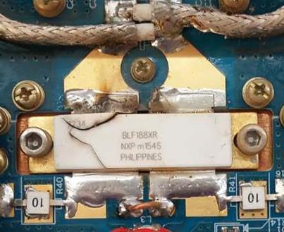

33 Something burnt Load Circulator Transistor 33
34 500MHz 100kW SSPA CWRF2018, June 2018, Taiwan 34
35 HEPS RF system 35


36 The prototype Call for tender Contract awarded to CASIC Deliver to IHEP 2-stage coaxial combiner Final stage waveguide combiner 36


37 The design 2kW power unit 25kW cabinet 37
38 Design requirements No. Parameter Target value 1 RF frequency 500MHz 2 Bandwidth ±2MHz (50kW output) 3 Mode CW/Pulse 4 Nominal output power 100kW 5 Power output at 1dB compression 100kW 6 Amplitude & phase stability ±1% and 7 Phase noise (1kHz carrier offset) -70dBc 8 Harmonic suppression -30dBc 9 Spurious suppression (carrier offset > 10kHz) -70dBc 10 Overall efficiency 50% 11 Redundancy >6% 38
39 Power coupler CWRF2018, June 2018, Taiwan 39
40 HEPS RF system 40


41 FPCs developed at IHEP The RF group has over a decade of experience on design, fabrication and power testing of FPCs and their beam operations. 41
42 166.6MHz FPC for SCC Parameter Frequency RF power Value MHz 200 kw CW External Q 3.78E4 Impedance of the coaxial line Ceramic type Cooling type Reflection coefficient Vacuum 50 Ω coaxial, planar Window & inner conductor: water-cooled Outer conductor: helium gas cooled S11< 20 db Bandwidth: ~15 MHz Leak rate: 1E-9 mbar l/sec Interface with power source Coaxial line, 9-3/16 42

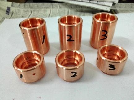


43 Fabrication Window T-box Launched in Completed in Outer conductor 43


44 The FPC 44
45 High power conditioning SSPA: Solid-State Power Amplifier TW: Travelling Wave SW: Standing Wave Power source Conditioning mode Remarks Phase I 166.6MHz 50kW solid-state amplifier TW & SW Limited by available SSPA power Phase II 650MHz 150kW solid-state amplifier TW Use a modified test stand 45


46 The setup 166MHz SSPA The complete setup for FPC high power conditioning using 166.6MHz 50kW SSPA LLRF control & monitoring 46
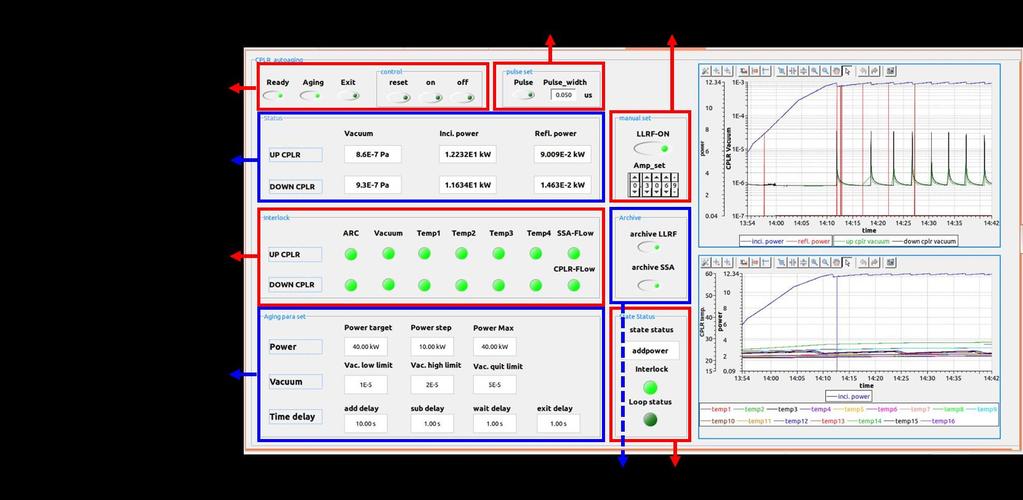


47 Automatic conditioning system 47
 - CW mode (10 hours) - Alternating pulsing and CW 48")
48 Conditioning in TW mode Maximum power reached: 50kW CW 166MHz SSPA After 1-hour power keep at 50kW CW: normal vacuum & temperature readouts Conditioning method - Pulsed mode (20 hours) - CW mode (10 hours) - Alternating pulsing and CW 48
 each time")

49 Conditioning in SW mode The short-circuit plane was moved by λ/8 (~225 mm) each time Maximum power reached: 50kW CW Conditioning method:pulsed mode and CW mode 166MHz SSPA 49
 on the upstream (downstream) window - Vacuum and temperature was normal during power keep 166MHz SSPA 50")
50 Conditioning in SW mode The electric antinode was moved along the FPC After 1-hour power keep at 50kW CW (E max on the ceramic window) - The temperature rise <4 C (6 C) on the upstream (downstream) window - Vacuum and temperature was normal during power keep 166MHz SSPA 50

 - One WG-box used for BEPCII 500MHz")
51 1043 mm HPC by 650MHz SSPA 650MHz SSPA To examine high power handling capability of the window, power conditioning at 150kW CW was implemented by using the existing 650MHz 150kW SSPA with a hybrid test bench setup. 650 MHz doorknob 500 MHz changed doorknob The RF optimization 650MHz components 166.6MHz FPC components 650MHz test bench The mechanical drawing The test bench system consists of - Two window inner-conductor assemblies of the 166.6MHz FPC - One doorknob from existing 650MHz FPC - One modified doorknob from existing 500MHz FPC (scaled to 650MHz) - One WG-box used for BEPCII 500MHz FPC conditioning 51


52 The setup 650MHz SSPA 650MHz 150kW SSPA 52


53 Temperature The temperatures were recorded during power keep at 150kW CW 650MHz SSPA Maximum temperature reached 55 C at T-sensor 9# of upstream FPC Window temperature below 35 C T-sensors Upstream Downstream 53

54 Summary HPRF system for the HEPS project has been designed and power sources are required Solid-state technology are adopted Power couplers at 166.6MHz for SRF cavity have been successfully conditioned High Energy Photon Source 54
55 What s next Working closely with our vendors for both 166.6MHz and 500MHz SSPA Better cooling for the 2kW power unit (power supply) Suppress current harmonics (40% 10%) Longer pulse (increase power storage elements in the power supply) Evaluate power combination schemes Questions? Output power linearity, early compression (efficiency)? From operation point of view? Output signal phase distortion, the cause? 55
56 Backup slides CWRF2018, June 2018, Taiwan 56
57 Power handling capability Dielectric loss: ~f Metal surface loss: ~f MHz 50kW SSPA [kw] 650MHz/166.6MHz = 3.9 Scaled to 166.6MHz 650MHz 150kW SSPA [kw] Ceramic window Metal part
Advance on High Power Couplers for SC Accelerators
 Advance on High Power Couplers for SC Accelerators Eiji Kako (KEK, Japan) IAS conference at Hong Kong for High Energy Physics, 2017, January 23th Eiji KAKO (KEK, Japan) IAS at Hong Kong, 2017 Jan. 23 1
Specification for Radiated susceptibility Test
 1 of 11 General Information on Radiated susceptibility test Supported frequency Range : 20MHz to 6GHz Supported Field strength : 30V/m at 3 meter distance 100V/m at 1 meter distance 2 of 11 Signal generator
Tutorial on Design of RF system for Indus Accelerator. Maherdra Lad Head, Radio Frequency Systems Division RRCAT, Indore
 Tutorial on Design of RF system for Indus Accelerator Maherdra Lad Head, Radio Frequency Systems Division RRCAT, Indore Basic principle of RF Acceleration RF Power Amplifier The RF source supplies power
Superconducting RF System. Heung-Sik Kang
 Design of PLS-II Superconducting RF System Heung-Sik Kang On behalf of PLS-II RF group Pohang Accelerator Laboratory Content 1. Introduction 2. Physics design 3. Cryomodules 4. Cryogenic system 5. High
FAST RF KICKER DESIGN
 FAST RF KICKER DESIGN David Alesini LNF-INFN, Frascati, Rome, Italy ICFA Mini-Workshop on Deflecting/Crabbing Cavity Applications in Accelerators, Shanghai, April 23-25, 2008 FAST STRIPLINE INJECTION KICKERS
REVIEW OF HIGH POWER CW COUPLERS FOR SC CAVITIES. S. Belomestnykh
 REVIEW OF HIGH POWER CW COUPLERS FOR SC CAVITIES S. Belomestnykh HPC workshop JLAB, 30 October 2002 Introduction Many aspects of the high-power coupler design, fabrication, preparation, conditioning, integration
CEBAF waveguide absorbers. R. Rimmer for JLab SRF Institute
 CEBAF waveguide absorbers R. Rimmer for JLab SRF Institute Outline Original CEBAF HOM absorbers Modified CEBAF loads for FEL New materials for replacement loads High power loads for next generation FELs
J. Jacob: Status of the ESRF RF upgrade
 17th ESLS RF Meeting 2013 HZB BESSY 18th 19th September Status of the ESRF RF upgrade J. Jacob J.-M. Mercier V. Serrière M. Langlois G. Gautier [CINEL] 1 RF upgrade phase 1 until 2015 - reminder Replacement
Couplers for Project X. S. Kazakov, T. Khabiboulline
 Couplers for Project X S. Kazakov, T. Khabiboulline TTC meeting on CW-SRF, 2013 Requirements to Project X couplers Cavity SSR1 (325MHz): Cavity SSR2 (325MHz): Max. energy gain - 2.1 MV, Max. power, 1 ma
Resonator System for the BEST 70MeV Cyclotron
 Resonator System for the BEST 70MeV Cyclotron 20 nd International Conference on Cyclotrons and their Applications Vancouver, Canada, September 16-20, 2013 Vasile Sabaiduc, Dipl. Eng. Accelerator Technology
10th ESLS RF Meeting September ALBA RF System. F. Perez. on behalf of the ALBA RF Group. ALBA RF System 1/21
 ALBA RF System F. Perez on behalf of the ALBA RF Group ALBA RF System 1/21 Synchrotron Light Source in Cerdanyola (Barcelona, Spain) 3 GeV accelerator 30 beamlines (7 on day one) 50-50 Spanish Government
Amplifier HF MHz
 Amplifier HF 1.5-30MHz multiple Amps Features Full color touchscreen display Linear solid state design Ultra efficient switching power supply Built in monitoring and control (remote port, Ethernet, SNMP)
RF POWER AMPLIFIER. For Accelerator Bunch-Beam-FeedBack R&K-GA005M R-SL
 All Solid-State Amplifier Broadband Frequency:5MHz~MHz Power :2W APPLICATION EMC(Electromagnetic Compatibility) Accelerator Application Telecommunication Test and Measurement Application Etc... OUTLINE
Coupler Electromagnetic Design
 Coupler Electromagnetic Design HPC Workshop, TJNAF October 30 November 1, 2002 Yoon Kang Spallation Neutron Source Oak Ridge National Laboratory Contents Fundamental Power Coupler Design Consideration
Jørgen S. Nielsen Center for Storage Ring Facilities (ISA) Aarhus University Denmark. ESLS-RF 22 (8/ ), ASTRID2 RF system 1
 Aarhus University Denmark. ESLS-RF 22 (8/ ), ASTRID2 RF system 1") Jørgen S. Nielsen Center for Storage Ring Facilities (ISA) Aarhus University Denmark ESLS-RF 22 (8/11 2018), ASTRID2 RF system 1 ASTRID2 is the new synchrotron light source in Aarhus, Denmark, since 2013
Jørgen S. Nielsen Center for Storage Ring Facilities (ISA) Aarhus University Denmark ESLS-RF 22 (8/11 2018), ASTRID2 RF system 1 ASTRID2 is the new synchrotron light source in Aarhus, Denmark, since 2013
Short-Pulse X-ray at the Advanced Photon Source Overview
 Short-Pulse X-ray at the Advanced Photon Source Overview Vadim Sajaev and Louis Emery Accelerator Operations and Physics Group Accelerator Systems Division Mini-workshop on Methods of Data Analysis in
Design and performance of LLRF system for CSNS/RCS *
 Design and performance of LLRF system for CSNS/RCS * LI Xiao 1) SUN Hong LONG Wei ZHAO Fa-Cheng ZHANG Chun-Lin Institute of High Energy Physics, Chinese Academy of Sciences, Beijing 100049, China Abstract:
OVERVIEW OF INPUT POWER COUPLER DEVELOPMENTS, PULSED AND CW*
 Presented at the 13th International Workshop on RF Superconductivity, Beijing, China, 2007 SRF 071120-04 OVERVIEW OF INPUT POWER COUPLER DEVELOPMENTS, PULSED AND CW* S. Belomestnykh #, CLASSE, Cornell
Uppsala, June 17 th - 19 th, 2013
 TIARA Workshop on RF Power Generation for Accelerators Uppsala, June 17 th - 19 th, 2013 Massamba DIOP, R. LOPES, P. MARCHAND, F. RIBEIRO SSA operation at SOLEIL BOOSTER 35 kw STORAGE RING 180 kw SOLEIL
The transition for the Elettra Input Power Coupler to the standard WR1800
 The transition for the Elettra Input Power Coupler to the standard WR1800 Cristina Pasotti, Mauro Bocciai, Luca Bortolossi, Alessandro Fabris, Marco Ottobretti, Mauro Rinaldi Alessio Turchet Sincrotrone
Yongming Li Institute of modern physics 31/07/2017
 Yongming Li Institute of modern physics 31/07/2017 2 Outline Motivation Coupler Design Operation Feedback Summary Project HIAF (2017-2024) SRing SRing: Spectrometer ring Circumference:290m Rigidity: 13Tm
MEASURES TO REDUCE THE IMPEDANCE OF PARASITIC RESONANT MODES IN THE DAΦNE VACUUM CHAMBER
 Frascati Physics Series Vol. X (1998), pp. 371-378 14 th Advanced ICFA Beam Dynamics Workshop, Frascati, Oct. 20-25, 1997 MEASURES TO REDUCE THE IMPEDANCE OF PARASITIC RESONANT MODES IN THE DAΦNE VACUUM
ALICE SRF SYSTEM COMMISSIONING EXPERIENCE A. Wheelhouse ASTeC, STFC Daresbury Laboratory
 ALICE SRF SYSTEM COMMISSIONING EXPERIENCE A. Wheelhouse ASTeC, STFC Daresbury Laboratory ERL 09 8 th 12 th June 2009 ALICE Accelerators and Lasers In Combined Experiments Brief Description ALICE Superconducting
Low-Level RF. S. Simrock, DESY. MAC mtg, May 05 Stefan Simrock DESY
 Low-Level RF S. Simrock, DESY Outline Scope of LLRF System Work Breakdown for XFEL LLRF Design for the VUV-FEL Cost, Personpower and Schedule RF Systems for XFEL RF Gun Injector 3rd harmonic cavity Main
Superconducting RF cavities activities for the MAX project
 1 Superconducting RF cavities activities for the MAX project OECD-NEA TCADS-2 Workshop Nantes, 22 May 2013 Marouan El Yakoubi, CNRS / IPNO 2 Contents 352 MHz spoke Cryomodule design 700 MHz test area 700
Status of the MAX IV RF systems. PPT-mall 2
 Status of the MAX IV RF systems PPT-mall 2 Lars Malmgren Med linje On Behalf of the MAX IV RF Group Åke Andersson, Joel Andersson, Richard Grandford, Sven-Olof Heed, Per Lilja, Dionis Kumbaro, Lars Malmgren,
Beam Diagnostics, Low Level RF and Feedback for Room Temperature FELs. Josef Frisch Pohang, March 14, 2011
 Beam Diagnostics, Low Level RF and Feedback for Room Temperature FELs Josef Frisch Pohang, March 14, 2011 Room Temperature / Superconducting Very different pulse structures RT: single bunch or short bursts
The BESSY Higher Order Mode Damped Cavity - Further Improvements -
 The BESSY Higher Order Mode Damped Cavity - Further Improvements - Ernst Weihreter Reminder of Technical Problems Solutions Conclusions BESSY HOM Damped Cavity Project collaboration: (EC funded) - BESSY
RF Design of Normal Conducting Deflecting Cavity
 RF Design of Normal Conducting Deflecting Cavity Valery Dolgashev (SLAC), Geoff Waldschmidt, Ali Nassiri (Argonne National Laboratory, Advanced Photon Source) 48th ICFA Advanced Beam Dynamics Workshop
HIGH POWER INPUT COUPLERS FOR THE STF BASELINE CAVITY SYSTEM AT KEK
 HIGH POWER INPUT COUPLERS FOR THE STF BASELINE CAVITY SYSTEM AT KEK E. Kako #, H. Hayano, S. Noguchi, T. Shishido, K. Watanabe and Y. Yamamoto KEK, Tsukuba, Ibaraki, 305-0801, Japan Abstract An input coupler,
Design, Development and Testing of RF Window for C band 250 kw CW Power Klystron
 Available online www.ejaet.com European Journal of Advances in Engineering and Technology, 2016, 3(6): 26-30 Research Article ISSN: 2394-658X Design, Development and Testing of RF Window for C band 250
NEW OPPORTUNITIES IN VACUUM ELECTRONICS USING PHOTONIC BAND GAP STRUCTURES
 NEW OPPORTUNITIES IN VACUUM ELECTRONICS USING PHOTONIC BAND GAP STRUCTURES J. R. Sirigiri, C. Chen, M. A. Shapiro, E. I. Smirnova, and R. J. Temkin Plasma Science and Fusion Center Massachusetts Institute
R.Bachimanchi, IPAC, May 2015, Richmond, VA
 1 new module C100 Cryomodule Seven cell Cavity, 0.7 m long (high Q L ) 8 Cavities per Cryomodule Fits the existing Cryomodule footprint Fundamental frequency f 0 Accelerating gradient E acc 1497 MHz >
Rigol DG1022A Function / Arbitrary Waveform Generator
 Rigol DG1022A Function / Arbitrary Waveform Generator The Rigol DG1000 series Dual-Channel Function/Arbitrary Waveform Generator adopts DDS (Direct Digital Synthesis) technology to provide stable, high-precision,
The low level radio frequency control system for DC-SRF. photo-injector at Peking University *
 The low level radio frequency control system for DC-SRF photo-injector at Peking University * WANG Fang( 王芳 ) 1) FENG Li-Wen( 冯立文 ) LIN Lin( 林林 ) HAO Jian-Kui( 郝建奎 ) Quan Sheng-Wen( 全胜文 ) ZHANG Bao-Cheng(
HIGH POWER COUPLER FOR THE TESLA TEST FACILITY
 Abstract HIGH POWER COUPLER FOR THE TESLA TEST FACILITY W.-D. Moeller * for the TESLA Collaboration, Deutsches Elektronen-Synchrotron DESY, D-22603 Hamburg, Germany The TeV Energy Superconducting Linear
Does the short pulse mode need energy recovery?
 Does the short pulse mode need energy recovery? Rep. rate Beam power @ 5GeV 1nC @ 100MHz 500MW Absolutely 1nC @ 10MHz 1nC @ 1MHz 50MW 5MW Maybe 1nC @ 100kHz 0.5MW No Most applications we have heard about
ESS-Bilbao Contribution to ESS Warm LINAC High Power RF Systems
 ESS-Bilbao Contribution to ESS Warm LINAC High Power RF Systems Arash Kaftoosian RF Group www.essbilbao.org On behalf of: Pedro Gonzalez Ibon Bustinduy RF Project Leader MEBT Project Leader ESS-Bilbao
2008 JINST 3 S The RF systems and beam feedback. Chapter Introduction
 Chapter 4 The RF systems and beam feedback 4.1 Introduction The injected beam will be captured, accelerated and stored using a 400 MHz superconducting cavity system, and the longitudinal injection errors
The VSX3622, a 1.5 kw X-Band GaN Power Amplifier for Radar Application
 The VSX3622, a 1.5 kw X-Band GaN Power Amplifier for Radar Application George Solomon, Dave Riffelmacher, Matt Boucher, Mike Tracy, Brian Carlson, Todd Treado Communications & Power Industries LLC, Beverly
Commissioning of the ALICE SRF Systems at Daresbury Laboratory Alan Wheelhouse, ASTeC, STFC Daresbury Laboratory ESLS RF 1 st 2 nd October 2008
 Commissioning of the ALICE SRF Systems at Daresbury Laboratory Alan Wheelhouse, ASTeC, STFC Daresbury Laboratory ESLS RF 1 st 2 nd October 2008 Overview ALICE (Accelerators and Lasers In Combined Experiments)
Mircea Stirbet. RF Conditioning: Systems and Procedures. Jefferson Laboratory
 Mircea Stirbet RF Conditioning: Systems and Procedures Jefferson Laboratory General requirements for input couplers - Sustain RF power required for operation of accelerator with beam - Do not compromise
Thermionic Bunched Electron Sources for High-Energy Electron Cooling
 Thermionic Bunched Electron Sources for High-Energy Electron Cooling Vadim Jabotinski 1, Yaroslav Derbenev 2, and Philippe Piot 3 1 Institute for Physics and Technology (Alexandria, VA) 2 Thomas Jefferson
C100 Cryomodule. Seven cell Cavity, 0.7 m long (high Q L ) 8 Cavities per Cryomodule Fits the existing Cryomodule footprint
 8 Cavities per Cryomodule Fits the existing Cryomodule footprint") 1 new module C100 Cryomodule Seven cell Cavity, 0.7 m long (high Q L ) 8 Cavities per Cryomodule Fits the existing Cryomodule footprint Fundamental frequency f 0 Accelerating gradient E acc 1497 MHz >
1 new module C100 Cryomodule Seven cell Cavity, 0.7 m long (high Q L ) 8 Cavities per Cryomodule Fits the existing Cryomodule footprint Fundamental frequency f 0 Accelerating gradient E acc 1497 MHz >
SRF in Storage Rings. Michael Pekeler ACCEL Instruments GmbH Bergisch Gladbach Germany
 SRF in Storage Rings Michael Pekeler ACCEL Instruments GmbH 51429 Bergisch Gladbach Germany SRF in Storage Rings Michael Pekeler ACCEL Instruments GmbH 51429 Bergisch Gladbach Germany TESLA type cavity:
Circumference 187 m (bending radius = 8.66 m)
") 4. Specifications of the Accelerators Table 1. General parameters of the PF storage ring. Energy 2.5 GeV (max 3.0 GeV) Initial stored current multi-bunch 450 ma (max 500 ma at 2.5GeV) single bunch 70 ma
4. Specifications of the Accelerators Table 1. General parameters of the PF storage ring. Energy 2.5 GeV (max 3.0 GeV) Initial stored current multi-bunch 450 ma (max 500 ma at 2.5GeV) single bunch 70 ma
SIGNAL GENERATORS. MG3633A 10 khz to 2700 MHz SYNTHESIZED SIGNAL GENERATOR GPIB
 SYNTHESIZED SIGNAL GENERATOR MG3633A GPIB For Evaluating of Quasi-Microwaves and Measuring High-Performance Receivers The MG3633A has excellent resolution, switching speed, signal purity, and a high output
Detailed Design Report
 Detailed Design Report Chapter 2 MAX IV 3 GeV Storage Ring 2.6. The Radio Frequency System MAX IV Facility CHAPTER 2.6. THE RADIO FREQUENCY SYSTEM 1(15) 2.6. The Radio Frequency System 2.6. The Radio Frequency
Agilent 83711B and 83712B Synthesized CW Generators
 View at www.testequipmentdepot.com Agilent 83711B and 83712B Synthesized CW Generators Agilent 83731B and 83732B Synthesized Signal Generators Data Sheet 10 MHz to 20 GHz 1 to 20 GHz Specifications describe
1.5 GHz Cavity design for the Clic Damping Ring and as Active Third Harmonic cavity for ALBA.
 1 1.5 GHz Cavity design for the Clic Damping Ring and as Active Third Harmonic cavity for ALBA. Beatriz Bravo Overview 2 1.Introduction 2.Active operation 3.Electromagnetic design 4.Mechanical design Introduction
Progresses on China ADS Superconducting Cavities
 Progresses on China ADS Superconducting Cavities Peng Sha IHEP, CAS 2013/06/12 1 Outline 1. Introduction 2. Spoke012 cavity 3. Spoke021 cavity 4. Spoke040 cavity 5. 650MHz β=0.82 5-cell cavity 6. High
Project of RF System for 2.2 GeV Electron Storage Ring Zelenograd SR Source.
 Project of RF System for 2.2 GeV Electron Storage Ring Zelenograd SR Source. I.K. Sedlyarov V.S. Arbuzov, E.I Gorniker, A.A. Kondakov, S.A. Krutikhin, G.Ya. Kurkin, I.V.Kuptsov, V.N. Osipov, V.M. Petrov,
The New Standard in High Power Redundant Microwave Amplifier Systems Has Arrived
 GaN MAX The New Standard in High Redundant Microwave Amplifier Systems Has Arrived FEATURES Gallium Nitride amplifiers, offering better power over frequency Output levels of up to: 10 kw in S-, C- and
The Current Cyclotron Development Activities at CIAE. Current acyclotron
 Current Cyclotron Development Activities Shizhong An, Tianjue Zhang China Institute of Atomic Energy (CIAE) Beijing 2010-11.22 Greatful acknowledged is very fruitful and long lasting collaboration with
電子回路論第 7 回 Electric Circuits for Physicists #7
 電子回路論第 7 回 Electric Circuits for Physicists #7 東京大学理学部 理学系研究科物性研究所勝本信吾 Shingo Katsumoto Outline 4.5 Field Effect Transistors (FETs) Ch.5 Distributed constant circuits 5.1 Transmission lines 5.1.1 Coaxial
RF Upgrade at DELTA. P. Hartmann DELTA, TU Dortmund
 RF Upgrade at DELTA P. Hartmann DELTA, TU Dortmund DELTA parameters: Personnel: Beam energy: 550 MeV 1.5 GeV Beam current: 130mA @ 1.5GeV Beam lifetime: 12h @ 130 ma Availability: 95 % Operational: 3000
Status of berlinpro and BESSY II Installation of SSA. Helmholtz-Zentrum Berlin for materials and energy (HZB)
") Status of berlinpro and BESSY II Installation of SSA Wolfgang Anders, Helmholtz-Zentrum Berlin for materials and energy (HZB) 19th ESLS-RF Meeting 30.9.-1.10.2015 MaxLab outline BERLinPro Status building
Status of berlinpro and BESSY II Installation of SSA Wolfgang Anders, Helmholtz-Zentrum Berlin for materials and energy (HZB) 19th ESLS-RF Meeting 30.9.-1.10.2015 MaxLab outline BERLinPro Status building
Specification of the kicker Measurement of the magnetic field inside the kicker Optimisation of the kicker impedance to 50 Status and picture of the
 Specification of the kicker Measurement of the magnetic field inside the kicker Optimisation of the kicker impedance to 50 Status and picture of the kicker The Specification of the Feedbackkicker technical
FISCHER CUSTOM COMMUNICATIONS, INC.
 FISCHER CUSTOM COMMUNICATIONS, INC. Current Probe Catalog FISCHER CUSTOM COMMUNICATIONS, INC. Fischer Custom Communications, Inc., is a manufacturer of custom electric and magnetic field sensors for military
Gyroklystron Research at CCR
 Gyroklystron Research at CCR RLI@calcreek.com Lawrence Ives, Michael Read, Jeff Neilson, Philipp Borchard and Max Mizuhara Calabazas Creek Research, Inc. 20937 Comer Drive, Saratoga, CA 95070-3753 W. Lawson
GA GHz. Digital Spectrum Analyzer
 Digital Spectrum Analyzer GA4063 3GHz Professional Performance Robust Measurement features High frequency stability Easy- to-use User Interface Compact size, Light weight, Portable design www.attenelectronics.com
PTX-0350 RF UPCONVERTER, MHz
 PTX-0350 RF UPCONVERTER, 300 5000 MHz OPERATING MODES I/Q upconverter RF = LO + IF upconverter RF = LO - IF upconverter Synthesizer 10 MHz REFERENCE INPUT/OUTPUT EXTERNAL LOCAL OSCILLATOR INPUT I/Q BASEBAND
The New Standard in High Power Redundant Microwave Amplifier Systems Has Arrived
 GaN MAX The New Standard in High Redundant Microwave Amplifier Systems Has Arrived FEATURES Gallium Nitride amplifiers, offering better power over frequency Output levels of up to: 10 kw in S-, C- and
The New Standard in High Power Redundant Microwave Amplifier Systems Has Arrived
 The New Standard in High Power Redundant Microwave Amplifier Systems Has Arrived FEATURES Output Power levels of: 8.0 kw in C-Band 6.6 kw in X-Band.5 kw in Ku-Band No Active Switching-All Passive Power
Dark Current Kicker Studies at FLASH
 Dark Current Kicker Studies at FLASH F. Obier, J. Wortmann, S. Schreiber, W. Decking, K. Flöttmann FLASH Seminar, DESY, 02 Feb 2010 History of the dark current kicker 2005 Vertical kicker was installed
THE PROTOTYPE FUNDAMENTAL POWER COUPLER FOR THE SPALLATION NEUTRON SOURCE SUPERCONDUCTING CAVITIES: DESIGN AND INITIAL TEST RESULTS*
 THE PROTOTYPE FUNDAMENTAL POWER COUPLER FOR THE SPALLATION NEUTRON SOURCE SUPERCONDUCTING CAVITIES: DESIGN AND INITIAL TEST RESULTS* K. M. Wilson,I.E.Campisi,E.F.Daly,G.K.Davis,M.Drury,J.E.Henry,P.Kneisel,G.
CHAPTER 4. Practical Design
 CHAPTER 4 Practical Design The results in Chapter 3 indicate that the 2-D CCS TL can be used to synthesize a wider range of characteristic impedance, flatten propagation characteristics, and place passive
HIGH POWER PULSED TESTS OF A BETA=0.5 5-CELL 704 MHZ SUPERCONDUCTING CAVITY
 HIGH POWER PULSED TESTS OF A BETA=0.5 5-CELL 704 MHZ SUPERCONDUCTING CAVITY G. Devanz, D. Braud, M. Desmons, Y. Gasser, E. Jacques, O. Piquet, J. Plouin, J.- P. Poupeau, D. Roudier, P. Sahuquet, CEA-Saclay,
Single-Supply, 150MHz, 16-Bit Accurate, Ultra-Low Distortion Op Amps
 9-; Rev ; /8 Single-Supply, 5MHz, 6-Bit Accurate, General Description The MAX4434/MAX4435 single and MAX4436/MAX4437 dual operational amplifiers feature wide bandwidth, 6- bit settling time in 3ns, and
MHz 58 db 1 KW RF Amplifier (EDA 00097)
") EUROPEAN ORGANIZATION FOR NUCLEAR RESEARCH CERN A&B DEPARTMENT AB-Note-2004-029 RF 0.2-10 58 1 KW RF Amplifier (EDA 00097) M. Paoluzzi 25 th March 2004 Geneva, Switzerland 1 1. DESCRIPTION 1.1. GENERAL
EUROPEAN ORGANIZATION FOR NUCLEAR RESEARCH CERN A&B DEPARTMENT AB-Note-2004-029 RF 0.2-10 58 1 KW RF Amplifier (EDA 00097) M. Paoluzzi 25 th March 2004 Geneva, Switzerland 1 1. DESCRIPTION 1.1. GENERAL
ESS RF Development at Uppsala University. Roger Ruber for the FREIA team Uppsala University
 ESS RF Development at Uppsala University Roger Ruber for the FREIA team Uppsala University ESS-UU Collaboration 2009 ESS and UU start discussion on 704 MHz RF development proposal for ESS dedicated test
RF & Microwave Amplifiers to 20GHz
 RF & Microwave Amplifiers to 20GHz Short form Catalog EuMW 2013 Low-Noise & Small Signal Power Amplifiers High Energy Physics Wideband GaN ECM Digital TV IMD Testing General Purpose Wideband Particle Physics,
Features 100A400AM20. 4kHz 400MHz Class A Portable Full VSWR tolerant CE & RoHS compliant High Efficiency
 Specifications Class A Portable Full VSWR tolerant CE & RoHS compliant High Efficiency Features The Model is a solid-state, self -contained, air-cooled, broadband amplifier designed for applications requiring
Acceleration of High-Intensity Protons in the J-PARC Synchrotrons. KEK/J-PARC M. Yoshii
 Acceleration of High-Intensity Protons in the J-PARC Synchrotrons KEK/J-PARC M. Yoshii Introduction 1. J-PARC consists of 400 MeV Linac, 3 GeV Rapid Cycling Synchrotron (RCS) and 50 GeV Main synchrotron
Radio Frequency Pulse Power Amplifier General Features
 Product Information Radio Frequency Pulse Power Amplifier General Features When we designed our pulse power amplifier series we had in mind the requirements of spectroscopic analysis, for instance Nuclear
Current Industrial SRF Capabilities and Future Plans
 and Future Plans Capabilities in view of Design Engineering Manufacturing Preparation Testing Assembly Taking into operation Future Plans Participate in and contribute to development issues, provide prototypes
Linear Particle Accelerator Control Performance
 Linear Particle Accelerator Control Performance 2007 ExpertTune-TiPS Conference April 17-19, 2007 Austin, TX Johnny Tang Overview of the Spallation Neutron Source Accelerator J. Tang 2 Overview of the
AWG-GS bit 2.5GS/s Arbitrary Waveform Generator
 KEY FEATURES 2.5 GS/s Real Time Sample Rate 14-bit resolution 2 Channels Long Memory: 64 MS/Channel Direct DAC Out - DC Coupled: 1.6 Vpp Differential / 0.8 Vpp > 1GHz Bandwidth RF Amp Out AC coupled -10
Advanced Test Equipment Rentals ATEC (2832) Agilent 8510 System Solutions
 Agilent 8510 System Solutions") E stablished 1981 Advanced Test Equipment Rentals www.atecorp.com 800-404-ATEC (2832) Agilent 8510 System Solutions Your bridge to the future Application guide The guide below shows Agilent Technologies
E stablished 1981 Advanced Test Equipment Rentals www.atecorp.com 800-404-ATEC (2832) Agilent 8510 System Solutions Your bridge to the future Application guide The guide below shows Agilent Technologies
Specification RIGOL. 6 Specification
 Specification RIGOL 6 Specification This chapter lists the specifications and general specifications of the analyzer. All the specifications are guaranteed when the following conditions are met unless
LEP Couplers..a Troubled Story of a Success. HPC2002, Jefferson Lab, October 30 th, 2002 R. Losito, CERN 1
 LEP Couplers..a Troubled Story of a Success HPC2002, Jefferson Lab, October 30 th, 2002 R. Losito, CERN 1 1 Overview & development: specifications, problems, solutions Operation: field equalization, trip
Jørgen S. Nielsen Institute for Storage Ring Facilities, Aarhus, University of Aarhus Denmark
 Jørgen S. Nielsen Institute for Storage Ring Facilities, Aarhus, University of Aarhus Denmark What is ISA? ISA operates and develops the storage ring ASTRID and related facilities ISA staff assist internal
Project X Cavity RF and mechanical design. T. Khabiboulline, FNAL/TD/SRF
 Project X Cavity RF and mechanical design T. Khabiboulline, FNAL/TD/SRF TTC meeting on CW-SRF, 2013 Project X Cavity RF and mechanical design T 1 High ß Low ß 0.5 HWR SSR1 SSR2 0 1 10 100 1 10 3 1 10 4
350MHz, Ultra-Low-Noise Op Amps
 9-442; Rev ; /95 EVALUATION KIT AVAILABLE 35MHz, Ultra-Low-Noise Op Amps General Description The / op amps combine high-speed performance with ultra-low-noise performance. The is compensated for closed-loop
TESLA RF POWER COUPLERS DEVELOPMENT AT DESY.
 TESLA RF POWER COUPLERS DEVELOPMENT AT DESY. Dwersteg B., Kostin D., Lalayan M., Martens C., Möller W.-D., DESY, D-22603 Hamburg, Germany. Abstract Different RF power couplers for the TESLA Test Facility
A Synchrotron Phase Detector for the Fermilab Booster
 FERMILAB-TM-2234 A Synchrotron Phase Detector for the Fermilab Booster Xi Yang and Rene Padilla Fermi National Accelerator Laboratory Box 5, Batavia IL 651 Abstract A synchrotron phase detector is diagnostic
SELECTING RF AMPLIFIERS FOR IMPEDANCE CONTROLLED LLRF SYSTEMS - NONLINEAR EFFECTS AND SYSTEM IMPLICATIONS. Abstract
 SLAC PUB 12636 July 27 SELECTING RF AMPLIFIERS FOR IMPEDANCE CONTROLLED LLRF SYSTEMS - NONLINEAR EFFECTS AND SYSTEM IMPLICATIONS John D. Fox, Themis Mastorides, Claudio Hector Rivetta and Daniel Van Winkle
High Power Couplers for TTF - FEL
 High Power Couplers for TTF - FEL 1. Requirements for High Power Couplers on superconducting Cavities 2. Characteristics of pulsed couplers 3. Standing wave pattern in the coaxial coupler line 4. Advantages
QUICK START GUIDE FOR DEMONSTRATION CIRCUIT 678A 40MHZ TO 900MHZ DIRECT CONVERSION QUADRATURE DEMODULATOR
 DESCRIPTION QUICK START GUIDE FOR DEMONSTRATION CIRCUIT 678A LT5517 Demonstration circuit 678A is a 40MHz to 900MHz Direct Conversion Quadrature Demodulator featuring the LT5517. The LT 5517 is a direct
BEPCII-THE SECOND PHASE CONSTRUCTION OF BEIJING ELECTRON POSITRON COLLIDER
 BEPCII-THE SECOND PHASE CONSTRUCTION OF BEIJING ELECTRON POSITRON COLLIDER C. Zhang, G.X. Pei for BEPCII Team IHEP, CAS, P.O. Box 918, Beijing 100039, P.R. China Abstract BEPCII, the second phase construction
Calibrating the Cavity Voltage. Presentation of an idea
 Calibrating the Cavity Voltage. Presentation of an idea Stefan Wilke, DESY MHF-e 21st ESLS rf meeting Kraków, 15th/16th nov 2017 Accelerators at DESY. linear and circular Page 2 Accelerators at DESY. linear
MEASURING HUM MODULATION USING MATRIX MODEL HD-500 HUM DEMODULATOR
 MEASURING HUM MODULATION USING MATRIX MODEL HD-500 HUM DEMODULATOR The SCTE defines hum modulation as, The amplitude distortion of a signal caused by the modulation of the signal by components of the power
High Speed BUFFER AMPLIFIER
 High Speed BUFFER AMPLIFIER FEATURES WIDE BANDWIDTH: MHz HIGH SLEW RATE: V/µs HIGH OUTPUT CURRENT: 1mA LOW OFFSET VOLTAGE: 1.mV REPLACES HA-33 IMPROVED PERFORMANCE/PRICE: LH33, LTC11, HS APPLICATIONS OP
Third Harmonic Superconducting passive cavities in ELETTRA and SLS
 RF superconductivity application to synchrotron radiation light sources Third Harmonic Superconducting passive cavities in ELETTRA and SLS 2 cryomodules (one per machine) with 2 Nb/Cu cavities at 1.5 GHz
GA GHz. Digital Spectrum Analyzer
 Digital Spectrum Analyzer GA4063 3GHz Professional Performance Robust Measurement features High frequency stability Easy- to-use User Interface Compact size, Light weight, Portable design www.attenelectronics.com
The Practical Limitations of S Parameter Measurements and the Impact on Time- Domain Simulations of High Speed Interconnects
 The Practical Limitations of S Parameter Measurements and the Impact on Time- Domain Simulations of High Speed Interconnects Dennis Poulin Anritsu Company Slide 1 Outline PSU Signal Integrity Symposium
Arbitrary/Function Waveform Generators 4075B Series
 Data Sheet Arbitrary/Function Waveform Generators Point-by-Point Signal Integrity The Arbitrary/Function Waveform Generators are versatile high-performance single- and dual-channel arbitrary waveform generators
Solid state RF amplifier development at ESRF
 Solid state RF amplifier development at ESRF Starring: The RF group with special thanks to Pierre Barbier, Philippe Chappelet, Alexandra Flaven-Bois and Denis Vial. Jean-Michel Chaize for advice on the
BESSY VSR: SRF challenges and developments for a variable pulse-length next generation light source
 BESSY VSR: SRF challenges and developments for a variable pulse-length next generation light source Institut SRF - Wissenschaft und Technologie (FG-ISRF) Adolfo Vélez et al. SRF17 Lanzhou, 17-21/7/2017
Receiver Design. Prof. Tzong-Lin Wu EMC Laboratory Department of Electrical Engineering National Taiwan University 2011/2/21
 Receiver Design Prof. Tzong-Lin Wu EMC Laboratory Department of Electrical Engineering National Taiwan University 2011/2/21 MW & RF Design / Prof. T. -L. Wu 1 The receiver mush be very sensitive to -110dBm