Mircea Stirbet. RF Conditioning: Systems and Procedures. Jefferson Laboratory
|
|
|
- Eleanor Boone
- 6 years ago
- Views:
Transcription
1 Mircea Stirbet RF Conditioning: Systems and Procedures Jefferson Laboratory
2 General requirements for input couplers - Sustain RF power required for operation of accelerator with beam - Do not compromise cavity performance (vacuum integrity, cleanliness) - Control multipacting, which could limit performances at certain power levels Geometry ( RF window, impedance) Vacuum design and associated instrumentation (RF and UHV specific materials, fast gauges and vacuum controllers) Instrumentation and controls (DC bias, optical ports for arc detectors, temperature and electron probes) - Sustain mechanical stresses during manufacturing, assembling, transportation, cooldown and operation. - Minimize cryogenic heat load - Ensure the requested Qexternal, minimize VSWR and insertion loss to avoid reflections and heating - Ensure high reliability in machine operation. - Satisfy different safety requirements (RF, HV, electrical, UHV, cryogenics, pressure)
3 Factors that limit RF window performances - heating of the vacuum barrier (ceramic) - multipactor discharge - cleanness - violent arcing High average power windows are most susceptible to the first two items. Multipactor discharge is a precarious surface phenomenon which is driven by the electric fields in the RF environment, being dependent on geometry, RF frequency and surface quality. It is addressed by applying an anti-multipactor coating (Ti or TiNx), proper cleaning, baking and RF conditioning. The Ti coating is RF lossy and contributes to the other problem encountered in high average power windows, heating of the ceramic. In addition to surface heating by the anti-multipactor coating, bulk heating of the ceramic occurs due to its non-zero dielectric loss tangent. If arcing events are triggered (local bad vacuum), the ceramic window could be metalized with subsequent higher RF losses and heating. It is mainly the problem of heating of the ceramic and the induced mechanical stress that limit the RF windows performances.
4 Factors that limit RF coupler performances On the air side of the coupler : - surface finish - RF contacts - dust, humidity - arcing events On the vacuum side of the coupler: - material quality (bulk and surface) - multipactor discharge -arcing events - vacuum and vacuum instrumentation - cooling
5 Conditioning fundamental power couplers All existing high power couplers exhibit severe outgassing and multipacting barriers of vacuum and RF exposed surfaces, as a result of geometrical configurations and surface conditions (material, contaminants, finishing). These problems can be overcome by design and different procedures like cleaning, baking followed by RF Conditioning - application of RF power under various conditions and in various configurations: On waveguide test stands or cavities. Pulsing the RF with different duty factors In continuous wave mode (CW) as traveling wave mode as standing wave mode Sweeping of frequency or RF power amplitude RF processing in conjunction with bias voltages Objective: to clean the surfaces from contaminants (molecular or particulate) and minimize conditions for multipacting. During this process the QA of different coupler components and associated instrumentation is obtained.
6 Standard conditioning procedure No Standard conditioning procedure can be found. Each laboratory has developed or is in the process of developing an optimum procedure for its coupler and RF test conditions. Many different methods are applied in succession such as TW processing, SW (off resonance) processing, frequency sweeping, power sweeping, bias voltage processing, warm and cold processing, with vacuum interlocking at different vacuum levels. The objective is always to touch surface area with RF, burn particulates and induce controlled gas layers desorption (they enhance the secondary electron emission coefficient and cause local desorption outbursts which could facilitate arcing events).
7 Aging couplers In all cases the fundamental power couplers are conditioned in a dedicated test stand (or on a cavity) at power levels at least two times higher than the power specified for machine operation. RF conditioned is done also after coupler is assembled on the cavity, before machine operation and after a long shutdown of the machine. If a cavity quenches in operation or trips by some other reason, all the forward power in the coupler is reflected and the coupler see local peak power between a minimum value and 4 times the input power level, crossing all predicted multipacting levels for a certain geometry. As couplers demonstrate RF conditioning memory, it seems important to age couplers at higher RF powers levels than used in machine operation.
8 Multipacting Electron Multipacting is a significant problem in vacuum and RF exposed surfaces and requires in most cases extensive RF conditioning. As in cavities, certain conditions have to be satisfied to generate multipacting events: An electron emitted from a wall of the line is under the influence of the EM fields returning to its origin within an integer number of RF cycles. The impacting electrons produce more than one electron, if the impact energy is high enough. Because in coaxial lines standing, traveling and mixed wave patterns can exit depending on the load conditions, multipacting is very complex in these systems and control methods shall be applied.
9 Multipacting simulations SNS FPC DC bias +1.9 / +2.4 kv Pasi Ylä-Oijala and Marko Ukkola, Multipacting Studies, Rolf Nevanlinna Institute, University of Helsinki, Finland
10 Resonator for multipacting studies MATERIAL N I[mA] N T[s] Copper Copper baked at 400 C Cu, stored one week in PE bag ; 1 >6500 TiN on Copper Titanium on Aluminum Titanium on Copper Cu Ti stored one week in PE bag ; 1 >6500 Aluminum >6500 Stainless Steel ; SS electrochemically Cu plated All samples show multipacting of at least first order. They differ in magnitude of multipacting current and in processing time. One interesting result is the dramatic deterioration of Cu and Ti coated Cu samples after storage in a plastic (PE) bag. Nevertheless, the common practice to store or transport RF components in plastic bags should be avoided, if multipacting is of concern. D. Proch et al., Measurement of multipacting currents of metal surfaces in rf fields, PAC 1995, p.1776
 stainless steel and form.")
11 KEKB Coupler The window of the input coupler has: A choke structure to decrease the electric field at the gold braze of the ceramic. The surface of the window on the vacuum side is coated with TiNxOy. The inner conductor is made of electro polished copper and is water-cooled. The waveguide transformer air-cooled. The outer conductor is copper plated (electrochemical) stainless steel and form. To control multipacting events, the doorknob inner conductor transition is separated via two layers of thick polyimide film. Instrumentation ports are located near the ceramic window (arc detector, vacuum gauge and electron pick up). For KEKB the input coupler is conditioned up to 300 kw or full-reflected power.

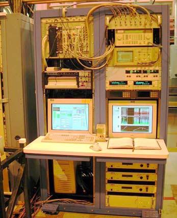
12 KEKB test stand
13 KEKB - HER ring Each coupler is processed with DC bias V and V up to 300 kw. Each time the cavity is warmed up, coupler conditioning is repeated. Power levels exceeding 380 kw with beam of 870 ma (950 ma) have been reported S. Mitsunobu, Operation Experience of Superconducting Cavities for KEKB, in : and HPC Workshop
14 KEKB conditioning with DC Bias Y.Kijima*, S.Mitsunobu, T.Furuya, T.Tajima, Input Coupler of Superconducting Cavity KEKB, EPAC 2000, Vienna, Austria,
15 KEKB - ARES cavity High-power test of the coupler with RF power in excess of 800 kw (twice as the ARES cavity requires). A dedicated coupler test stand consisting of a small cylindrical cavity connecting two couplers to the RF klystron and to a dummy load was built. Different design couplers have been tested up to 950 kw in this configuration. F.Naito et al., The Input coupler for the KEKB ARES cavity, in : APAC98,


16 KEK MHz 792 MHz window assembly Components for 972 MHz couplers


17 KEK MHz Room temperature test stand for 972 MHz couplers

18 KEK MHz JAERI instrumentation for high RF power tests Vacuum pumping system Vacuum gauges and controllers Residual Gas Analyzer
19 KEK MHz Results Specification Preparation External Q value : 5 x10 5 Required rf input power : 250 kw (Beam current = 30 ma) Pulsed operation Cleaning Assembling Baking Vacuum pressure High Power Test : ~3.0 msec, 25 Hz : rinsing with ultra-pure water : in the clean room : around 120 o C for 24 hours : less than 10-6 Pa Number of couplers : 2 couplers Result of processing : 340 kw (2.45 msec, 25Hz) Limitation Problem : nothing : 1.0 MW (0.6 msec, 25Hz) : available rf power of Klystron

20 KEK RF conditioning The coupler was newly designed being based on that for the 508 MHz APS cavity of TRISTAN ring. - initial vacuum Torr - start RF conditioning in CW at ~100 W and increase RF power keeping the vacuum better than Torr. The RFL power was used as interlock - 60 kw are reached in 60 hours. - with RF OFF vacuum is Torr - baking is done at 150 C for 24 hours and vacuum is improved at Torr - RF processing by pulsing RF 10% duty cycle allows reaching 100 kw in 12 hours. - Continue RF conditioning in CW and 150 kw are obtained without problems after a total of 60 hours. T. Koseki et al., High-Power Conditioning of an RF Cavity for High Brilliant Synchrotron Radiation Source, EPAC 1996,
21 DESY
22 DESY

23 DESY Results RF conditioning computer controlled, starting with small pulse duration. Interlocks on electron activity and arcing. Electronic module to control RF amplitude as function of vacuum outburst made but not yet in use.

24 LEP2-50 ohm variable coupler


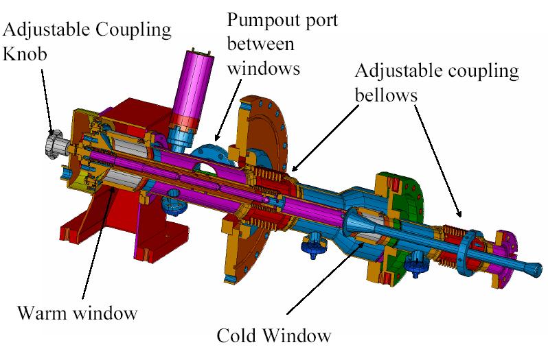
25 LEP2 - components for the 75 ohm fix coupler LEP2 Power Coupler Air inlet antenna RF screen and HV protection HV connection Air inlet doorknob Doorknob Kapton foil Capacitor for DC bias Waveguide UHV gauge port Ceramic window Assembly body He gas outlet Insulating vacuum Antenna (copper) Extension (copper plated stainless steel) 75 Ω Coaxial line 4.2 o K He gas inlet Cavity vacuum Liquid helium CW max 125 kw


26 LEP2 - waveguide and alternative DC bias system


27 LEP2 - doorknob and capacitor for DC bias
28 LEP2 - RF conditioning of couplers All main power couplers have been preconditioned and qualified on a room temperature test stand. RF conditioning was always preceded by cleaning, assembling in a clean room and by baking for 24 hours at 200 C, then RF processing was started in pulse mode, with small pulse duration and low amplitude, followed by CW processing by cycling the RF power between two power levels or performing constant power tests. Necessary time: hours for RF processing if assisted by fast vacuum feedback loop. On cold test modules (with five or single cell(s) cavity) - similar RF conditioning was used and and results regarding procedures and different coupler components (long term high RF power tests, baking in situ, He pulse processing of cavities, DC bias, copper plating methods for the outer conductors) were obtained. LEP2 couplers have been conditioned cryo modules in String area before installation the machine. LEP2 couplers have been re-conditioned after shut-downs. In String area, RF conditioning was done as function of cavity field (not RF power) and the time needed to qualify a module for installation in the machine was about three weeks.


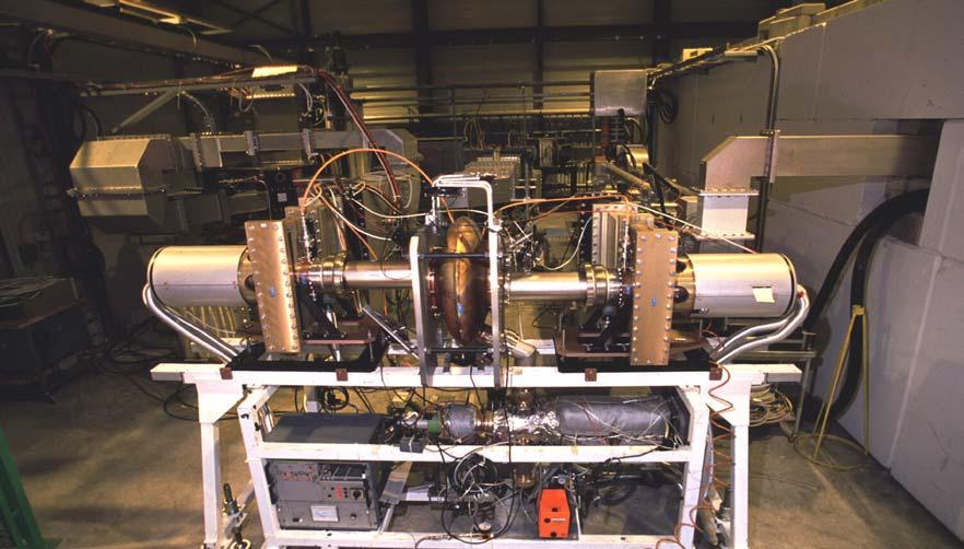
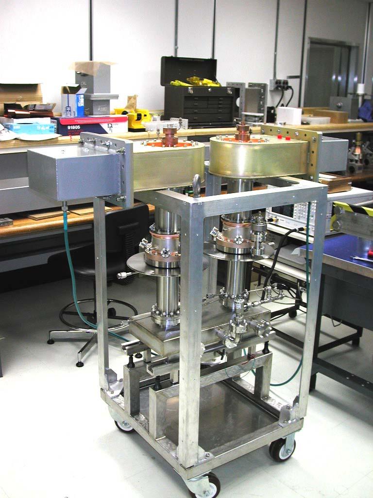
29 LEP2 - room temperature test cart Room temperature test cart for LEP couplers

30 LEP2 - LHe module for testing cavities and couplers

31 LEP2 - single cell LHe module setup
32 LEP2 - Procedure for RF conditioning All main couplers mounted in LEP2 on SC modules have been RF processed according with the following procedure: Pulsed RF (1-10 ms pulse length and ms repetition rate). The use of a fast analog vacuum feedback loop was essential. Cycling the RF power kw, with different rise times (controlled by a computer program in addition to the fast analog vacuum loop). Cycling the RF power kw for about 1 hour, followed by a test at constant of several hours at 150 kw, then by another cycling kw. Cycling again kw for several hours, during this time the DC bias efficiency in suppressing multipactor events was tested. After RF processing at room temperature, couplers have been stored in stainless steel containers, under dry, dust free nitrogen.


33 LEP2 - pulse modulation Vacuum feedback loop RF pulse modulation
34 LEP2 - RF conditioning
35 LEP - Results More than 300 main power couplers have been qualified (in CW, traveling mode up to 250 kw ) on test room temperature test stand for assembly on the LEP SC cavities. After RF conditioning, machine operation have not been hindered by couplers problems - less than 5% of RF trips have been due to Coupler vacuum during machine operation. DC bias had a major contribution in ensuring stable machine operation (multipacting free) for more than 5 years. The reliability of the main power couplers have allowed to transfer higher RF power values and so to increase the cavity fields from the design value of 6 MV/m to more than 7.5 MV/m. None of the 288 power couplers broke during the whole life of LEP2 and only a small fraction of the machine down time was due to superconducting RF - a much smaller fraction than due to conventional equipment faults.
36 LEP final
37 LHC main power coupler Variable input couplers, providing a remotely controlled change of external Q by an order of magnitude under power, are required for the 400 MHz LHC superconducting cavities. These couplers must handle a forward power of 120 kw average and 180 kw pulsed (with about 50 ms pulse duration) under a large variety of load conditions up to full reflection.
 RF screen and HV protection 7 Ω Coaxial line")
 75 Ω Coaxial line (under")
38 LHC variable main coupler Air cooling inlet Air inlet antenna Displacement mechanism (60 mm stroke) RF screen and HV protection 7 Ω Coaxial line (under vacuum) Air pressure interlock Bellows Motor drive Capacitor for DC bias Waveguide Ceramic window Antenna (copper) 75 Ω Coaxial line (under vacuum)

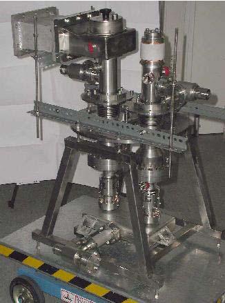
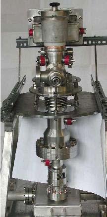
39 LHC baking and room temperature test devices
40 LHC variable couplers - RF conditioning RF conditioning was done as function of coupler vacuum (a fast vacuum feedback loop controlling the RF power). On room temperature test cart: - In traveling wave mode started with pulse (small duration, low repetition rate) up to 500 kw, then in CW from 1 kw up to 500 kw (klystron limit). After conditioning, long term RF power tests have been performed in traveling wave : at 400 kw for more than 150 hours and at 500 kw (maximum klystron power) for about 50 hours. - In standing wave mode, conditioning at any phase and any coupling has been achieved up to the maximum klystron power. Up to 500 kw forward power (2 MW equivalent peak power) has been reached with pulses of 50 ms duration and of 10% duty cycle. On LHC cold bi-module: Each coupler was RF conditioned using our standard procedure starting with loose coupling, small pulses and low duty factor, then changing to CW mode and continued with to stronger coupling by changing the penetration of the antenna in steps up to the cavity field limit or other RF components (elbows, terminating loads).
41 LHC RF - vacuum feedback during conditioning

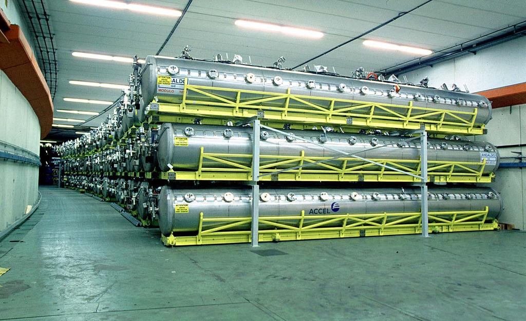
42 LHC variable main power couplers on a bimodule

43 LEP and LHC controls for room temperature qualification
44 LHC variable coupler performance On room temperature test stand: In travelling wave mode: kw (limited by klystron) for more than 50 hours kw for more than 150 hours In pure standing wave mode (any phase, any coupling) 500 kw forward power (2 MW equivalent peak power) with pulsed RF (50 ms, 10% duty cycle). On superconducting cavity: More than one order of magnitude of the Qext has been achieved by changing the position of the antenna. Only several hours of RF conditioning were needed to reach 300 kw (limit by the terminating load on the circulator) or 3 MV/m (cavity field limit).
45 LEP2 NEG coating
46 LEP2 NEG coating - 2
47 LEP2 NEG coating - 3
 NA Impedance 50 Ohm Peak power 550 kw 1 MW(TW).5MW (SW) Pulse length 1.3 ms 1.")
48 JLAB - SNS - FPC design parameters Design parameters Parameter in Operation in Processing Q ext 7.3 / 7.0 x 10 5 (20%) NA Impedance 50 Ohm Peak power 550 kw 1 MW(TW).5MW (SW) Pulse length 1.3 ms 1.3 ms Repetition rate 60 pps 60 pps max average power 48 kw 60 kw Bias ± 2.5 kv ± 2.5 kv

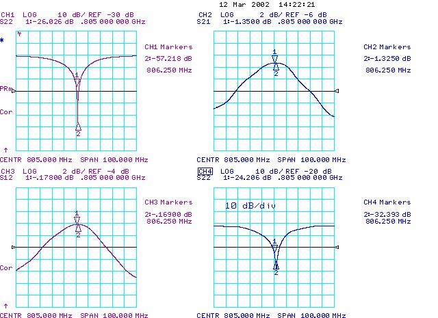
49 JLAB - SNS low RF power measurements


50 JLAB - SNS baking FPCs Baking at 200 ºC for 24 hrs temperature ramping with 10 ºC/h

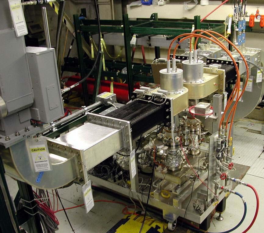
51 JLAB - SNS - FPCs Instrumentation
52 JLAB - SNS - RF conditioning Start RF conditioning in traveling wave mode with small pulse duration, amplitude and low duty cycle, under the control of the feedback vacuum loop ant of the computer program (expect explosive vacuum outbursts for 6-8 hours),. Change pulse characteristics as function of vacuum and electron activity. If arcing in the vacuum side of the coupler, change vacuum threshold. After reaching 1 MW, cycle the RF amplitude for several hours between two power levels (1-800 kw) and/or keep the RF constant at a certain power level for at least 24 hours. Test DC bias efficiency in controlling multipacting events Perform RF conditioning in standing wave mode, using pulse duration smaller than the nominal value. For a certain position of the short circuit increase the input RF power from a minimum value up to a designated value, conditioning multipacting levels.

53 JLAB - SNS vacuum RF amplitude modulation During RF conditioning a complex series of events occurs on the vacuum side of the coupler. Safe RF processing: limiting pressure rise to mbar and responding to explosive vacuum events with fast vacuum gauges and controllers. Fast gauges, vacuum controllers and RF amplitude feedback loops are indispensable for safe RF processing.
.")
54 JLAB - SNS RF conditioning Cycling, keeping constant, and again cycling the RF power between kw (1 ms, 60 Hz).

55 JLAB - SNS RF conditioning - 2

56 JLAB - SNS RF conditioning - 3
57 JLAB - SNS RF conditioning RF Power through the Jlab Coupler August 21st - August 30th, Aug 21, 2001 Aug 22, 2001 Aug 23, 2001 Aug 24, 2001 Aug 27, 2001 Aug 28, 2001 Aug 29, 2001 Aug 30, Test Time (Hr)

58 Conditioning and testing - multipacting Multipacting at 120 and 480 kw

59 JLAB - SNS - DC bias A B C D Cycling RF: A: - no DC bias B: +2.5 kv C: kv D: - no DC bias ( kw, 60 sec on top, pulse 1 ms, 60 Hz)

60 JLAB - SNS - RGA during RF conditioning A B RGA while cycling kw with DC bias: - A with kv - B with +2.5 kv
61 JLAB - SNS - Results RF tests performed at LANL at room temperature: In TW mode reaching 2 MW with 0.6 ms pulse width at 60 Hz repetition rate, transferring an average power of more than 70 kw. In SW mode: local RF peak power in excess of 2 MW. RF tests performed at JLAB 1 MW room temperature test facility: In TW mode up to 1 MW (1 ms, 30 Hz repetition rate) (long term tests in CW 550 kw, 1 ms with 60 Hz repetition rate) In SW mode more than 2 MW local peak power RF tests at JLAB on cryomodule: on the first coupler tested on the cryomodule, 16 mv/m were obtained after only 5 hours of RF conditioning. Later, 700 kw in full reflection with 1 ms pulses have been reported without problems.

62 Guide d onde (magic T)
63 Conclusions Efficient RF conditioning and multipacting control: Assembly of components with surfaces exposed to vacuum and RF in a clean room. Avoid moisture and plastic bags during storage. Titanium coating of ceramic on the vacuum side. Apply outbaking procedure before RF processing. Efficient vacuum and electron current measurements near critical components. Avoid RF overheating of critical components. Conditioning should start with pulsed (low amplitude and duty factor) RF followed by cycling the RF power, or keeping the power constant for at least 24 hours, under the control of a fast vacuum feedback loop and/or of a computer program (allow for out gassing of less than mbar). Keep the RF processed components under dry, dust free nitrogen. Start RF conditioning of couplers on SC cavity with warm outer conductors. Apply nominal value DC bias only after RF conditioning.
REVIEW OF HIGH POWER CW COUPLERS FOR SC CAVITIES. S. Belomestnykh
 REVIEW OF HIGH POWER CW COUPLERS FOR SC CAVITIES S. Belomestnykh HPC workshop JLAB, 30 October 2002 Introduction Many aspects of the high-power coupler design, fabrication, preparation, conditioning, integration
RF power tests of LEP2 main couplers on a single cell superconducting cavity
 RF power tests of LEP2 main couplers on a single cell superconducting cavity H.P. Kindermann, M. Stirbet* CERN, CH-1211 Geneva 23, Switzerland Abstract To determine the power capability of the input couplers
TESLA RF POWER COUPLERS DEVELOPMENT AT DESY.
 TESLA RF POWER COUPLERS DEVELOPMENT AT DESY. Dwersteg B., Kostin D., Lalayan M., Martens C., Möller W.-D., DESY, D-22603 Hamburg, Germany. Abstract Different RF power couplers for the TESLA Test Facility
Couplers for Project X. S. Kazakov, T. Khabiboulline
 Couplers for Project X S. Kazakov, T. Khabiboulline TTC meeting on CW-SRF, 2013 Requirements to Project X couplers Cavity SSR1 (325MHz): Cavity SSR2 (325MHz): Max. energy gain - 2.1 MV, Max. power, 1 ma
HIGH POWER INPUT COUPLERS FOR THE STF BASELINE CAVITY SYSTEM AT KEK
 HIGH POWER INPUT COUPLERS FOR THE STF BASELINE CAVITY SYSTEM AT KEK E. Kako #, H. Hayano, S. Noguchi, T. Shishido, K. Watanabe and Y. Yamamoto KEK, Tsukuba, Ibaraki, 305-0801, Japan Abstract An input coupler,
HIGH POWER COUPLER FOR THE TESLA TEST FACILITY
 Abstract HIGH POWER COUPLER FOR THE TESLA TEST FACILITY W.-D. Moeller * for the TESLA Collaboration, Deutsches Elektronen-Synchrotron DESY, D-22603 Hamburg, Germany The TeV Energy Superconducting Linear
THE PROTOTYPE FUNDAMENTAL POWER COUPLER FOR THE SPALLATION NEUTRON SOURCE SUPERCONDUCTING CAVITIES: DESIGN AND INITIAL TEST RESULTS*
 THE PROTOTYPE FUNDAMENTAL POWER COUPLER FOR THE SPALLATION NEUTRON SOURCE SUPERCONDUCTING CAVITIES: DESIGN AND INITIAL TEST RESULTS* K. M. Wilson,I.E.Campisi,E.F.Daly,G.K.Davis,M.Drury,J.E.Henry,P.Kneisel,G.
LEP Couplers..a Troubled Story of a Success. HPC2002, Jefferson Lab, October 30 th, 2002 R. Losito, CERN 1
 LEP Couplers..a Troubled Story of a Success HPC2002, Jefferson Lab, October 30 th, 2002 R. Losito, CERN 1 1 Overview & development: specifications, problems, solutions Operation: field equalization, trip
Coupler Electromagnetic Design
 Coupler Electromagnetic Design HPC Workshop, TJNAF October 30 November 1, 2002 Yoon Kang Spallation Neutron Source Oak Ridge National Laboratory Contents Fundamental Power Coupler Design Consideration
OVERVIEW OF INPUT POWER COUPLER DEVELOPMENTS, PULSED AND CW*
 Presented at the 13th International Workshop on RF Superconductivity, Beijing, China, 2007 SRF 071120-04 OVERVIEW OF INPUT POWER COUPLER DEVELOPMENTS, PULSED AND CW* S. Belomestnykh #, CLASSE, Cornell
Advance on High Power Couplers for SC Accelerators
 Advance on High Power Couplers for SC Accelerators Eiji Kako (KEK, Japan) IAS conference at Hong Kong for High Energy Physics, 2017, January 23th Eiji KAKO (KEK, Japan) IAS at Hong Kong, 2017 Jan. 23 1
SUPPRESSING ELECTRON MULTIPACTING IN TTF III COLD WINDOW BY DC BIAS
 SUPPRESSING ELECTRON MULTIPACTING IN TTF III COLD WINDOW BY DC BIAS PASI YLÄ-OIJALA and MARKO UKKOLA Rolf Nevanlinna Institute, University of Helsinki, PO Box 4, (Yliopistonkatu 5) FIN 4 Helsinki, Finland
High Power Couplers for TTF - FEL
 High Power Couplers for TTF - FEL 1. Requirements for High Power Couplers on superconducting Cavities 2. Characteristics of pulsed couplers 3. Standing wave pattern in the coaxial coupler line 4. Advantages
DEVELOPMENTS OF HORIZONTAL HIGH PRESSURE RINSING FOR SUPERKEKB SRF CAVITIES
 DEVELOPMENTS OF HORIZONTAL HIGH PRESSURE RINSING FOR SUPERKEKB SRF CAVITIES Y. Morita #, K. Akai, T. Furuya, A. Kabe, S. Mitsunobu, and M. Nishiwaki Accelerator Laboratory, KEK, Tsukuba, Ibaraki 305-0801,
TESTS AND DESIGNS OF HIGH-POWER WAVEGUIDE VACUUM WINDOWS AT CORNELL
 TESTS AND DESIGNS OF HIGH-POWER WAVEGUIDE VACUUM WINDOWS AT CORNELL E. Chojnacki, P. Barnes, S. Belomestnykh, R. Kaplan, J. Kirchgessner, H. Padamsee, P. Quigley, J. Reilly, and J. Sears CORNELL UNIVERSITY,
Design and technology of high-power couplers, with a special view on superconducting RF
 Design and technology of high-power couplers, with a special view on superconducting RF W.-D. Möller Deutsches Elektronen-Synchrotron, Hamburg, Germany Abstract The high-power RF coupler is the connecting
ALICE SRF SYSTEM COMMISSIONING EXPERIENCE A. Wheelhouse ASTeC, STFC Daresbury Laboratory
 ALICE SRF SYSTEM COMMISSIONING EXPERIENCE A. Wheelhouse ASTeC, STFC Daresbury Laboratory ERL 09 8 th 12 th June 2009 ALICE Accelerators and Lasers In Combined Experiments Brief Description ALICE Superconducting
Superconducting RF cavities activities for the MAX project
 1 Superconducting RF cavities activities for the MAX project OECD-NEA TCADS-2 Workshop Nantes, 22 May 2013 Marouan El Yakoubi, CNRS / IPNO 2 Contents 352 MHz spoke Cryomodule design 700 MHz test area 700
SUPERCONDUCTING PROTOTYPE CAVITIES FOR THE SPALLATION NEUTRON SOURCE (SNS) PROJECT *
 PROJECT *") SUPERCONDUCTING PROTOTYPE CAVITIES FOR THE SPALLATION NEUTRON SOURCE (SNS) PROJECT * G. Ciovati, P. Kneisel, J. Brawley, R. Bundy, I. Campisi, K. Davis, K. Macha, D. Machie, J. Mammosser, S. Morgan, R.
SUPERCONDUCTING PROTOTYPE CAVITIES FOR THE SPALLATION NEUTRON SOURCE (SNS) PROJECT * G. Ciovati, P. Kneisel, J. Brawley, R. Bundy, I. Campisi, K. Davis, K. Macha, D. Machie, J. Mammosser, S. Morgan, R.
RF STATUS OF SUPERCONDUCTING MODULE DEVELOPMENT SUITABLE FOR CW OPERATION: ELBE CRYOSTATS
 RF STATUS OF SUPERCONDUCTING MODULE DEVELOPMENT SUITABLE FOR CW OPERATION: ELBE CRYOSTATS J. Teichert, A. Büchner, H. Büttig, F. Gabriel, P. Michel, K. Möller, U. Lehnert, Ch. Schneider, J. Stephan, A.
Frequency Tuning and RF Systems for the ATLAS Energy Upgrade. Gary P. Zinkann
 Frequency Tuning and RF Systems for the ATLAS Energy Upgrade Outline Overview of the ATLAS Energy Upgrade Description of cavity Tuning method used during cavity construction Description and test results
SNS CRYOMODULE PERFORMANCE*
 SNS CRYOMODULE PERFORMANCE* J. Preble*, I. E. Campisi, E. Daly, G. K. Davis, J. R. Delayen, M. Drury, C. Grenoble, J. Hogan, L. King, P. Kneisel, J. Mammosser, T. Powers, M. Stirbet, H. Wang, T. Whitlatch,
Current Industrial SRF Capabilities and Future Plans
 and Future Plans Capabilities in view of Design Engineering Manufacturing Preparation Testing Assembly Taking into operation Future Plans Participate in and contribute to development issues, provide prototypes
2008 JINST 3 S The RF systems and beam feedback. Chapter Introduction
 Chapter 4 The RF systems and beam feedback 4.1 Introduction The injected beam will be captured, accelerated and stored using a 400 MHz superconducting cavity system, and the longitudinal injection errors
CEBAF waveguide absorbers. R. Rimmer for JLab SRF Institute
 CEBAF waveguide absorbers R. Rimmer for JLab SRF Institute Outline Original CEBAF HOM absorbers Modified CEBAF loads for FEL New materials for replacement loads High power loads for next generation FELs
Processing and Testing of PKU 3-1/2 Cell Cavity at JLab
 Processing and Testing of PKU 3-1/2 Cell Cavity at JLab Rongli Geng, Byron Golden August 7, 2009 Introduction The SRF group at Peking University has successfully built a 3-1/2 cell superconducting niobium
Design, Development and Testing of RF Window for C band 250 kw CW Power Klystron
 Available online www.ejaet.com European Journal of Advances in Engineering and Technology, 2016, 3(6): 26-30 Research Article ISSN: 2394-658X Design, Development and Testing of RF Window for C band 250
Fundamental mode rejection in SOLEIL dipole HOM couplers
 Fundamental mode rejection in SOLEIL dipole HOM couplers G. Devanz, DSM/DAPNIA/SACM, CEA/Saclay, 91191 Gif-sur-Yvette 14th June 2004 1 Introduction The SOLEIL superconducting accelerating cavity is a heavily
DEVELOPMENT OF A BETA 0.12, 88 MHZ, QUARTER WAVE RESONATOR AND ITS CRYOMODULE FOR THE SPIRAL2 PROJECT
 DEVELOPMENT OF A BETA 0.12, 88 MHZ, QUARTER WAVE RESONATOR AND ITS CRYOMODULE FOR THE SPIRAL2 PROJECT G. Olry, J-L. Biarrotte, S. Blivet, S. Bousson, C. Commeaux, C. Joly, T. Junquera, J. Lesrel, E. Roy,
Commissioning of the ALICE SRF Systems at Daresbury Laboratory Alan Wheelhouse, ASTeC, STFC Daresbury Laboratory ESLS RF 1 st 2 nd October 2008
 Commissioning of the ALICE SRF Systems at Daresbury Laboratory Alan Wheelhouse, ASTeC, STFC Daresbury Laboratory ESLS RF 1 st 2 nd October 2008 Overview ALICE (Accelerators and Lasers In Combined Experiments)
Third Harmonic Superconducting passive cavities in ELETTRA and SLS
 RF superconductivity application to synchrotron radiation light sources Third Harmonic Superconducting passive cavities in ELETTRA and SLS 2 cryomodules (one per machine) with 2 Nb/Cu cavities at 1.5 GHz
Coupler functions. G.devanz CEA-Saclay CAS Bilbao may
 Coupler and tuners Coupler functions Inject RF power generated by the RF source into the cavity and beam, Maximize power transmission at the nominal frequency f ( or eqv. minimizing reflection ), Form
Packaging of Cryogenic Components
 Packaging of Cryogenic Components William J. Schneider Senior Mechanical Engineer Emeritus November 19-23 2007 1 Packaging of Cryogenic Components Day one Introduction and Overview 2 What is important?
HIGH POWER PULSED TESTS OF A BETA=0.5 5-CELL 704 MHZ SUPERCONDUCTING CAVITY
 HIGH POWER PULSED TESTS OF A BETA=0.5 5-CELL 704 MHZ SUPERCONDUCTING CAVITY G. Devanz, D. Braud, M. Desmons, Y. Gasser, E. Jacques, O. Piquet, J. Plouin, J.- P. Poupeau, D. Roudier, P. Sahuquet, CEA-Saclay,
On behalf of: Sang-hoon Kim Zack Conway Mark Kedzie Tom Reid Ben Guilfoyle
 On behalf of: Sang-hoon Kim Zack Conway Mark Kedzie Tom Reid Ben Guilfoyle $SSOLFDWLRQV IRU $1/ &RD[LDO &RXSOHUV $7/$6 0+] 0RGXOH )5,% 4:5V FRIB SRF production status: cavities, ancillaries SRF17, T.
Superconducting RF System. Heung-Sik Kang
 Design of PLS-II Superconducting RF System Heung-Sik Kang On behalf of PLS-II RF group Pohang Accelerator Laboratory Content 1. Introduction 2. Physics design 3. Cryomodules 4. Cryogenic system 5. High
Yongming Li Institute of modern physics 31/07/2017
 Yongming Li Institute of modern physics 31/07/2017 2 Outline Motivation Coupler Design Operation Feedback Summary Project HIAF (2017-2024) SRing SRing: Spectrometer ring Circumference:290m Rigidity: 13Tm
THE MULTIPACTING STUDY OF NIOBIUM SPUTTERED HIGH-BETA QUARTER-WAVE RESONATORS FOR HIE-ISOLDE
 THE MULTIPACTING STUDY OF NIOBIUM SPUTTERED HIGH-BETA QUARTER-WAVE RESONATORS FOR HIE-ISOLDE P. Zhang and W. Venturini Delsolaro CERN, Geneva, Switzerland Abstract Superconducting Quarter-Wave Resonators
Detailed Design Report
 Detailed Design Report Chapter 2 MAX IV 3 GeV Storage Ring 2.6. The Radio Frequency System MAX IV Facility CHAPTER 2.6. THE RADIO FREQUENCY SYSTEM 1(15) 2.6. The Radio Frequency System 2.6. The Radio Frequency
THE HIGH LUMINOSITY PERFORMANCE OF CESR WITH THE NEW GENERATION SUPERCONDUCTING CAVITY
 Presented at the 1999 Particle Accelerator Conference, New York City, NY, USA, March 29 April 2 CLNS 99/1614 / SRF 990407-03 THE HIGH LUMINOSITY PERFORMANCE OF CESR WITH THE NEW GENERATION SUPERCONDUCTING
The HPRF system for a new 6 GeV synchrotron light source in Beijing
 中国科学院高能物理研究所 INSTITUTE OF HIGH ENERGY PHYSICS CHINESE ACADEMY OF SCIENCES The HPRF system for a new 6 GeV synchrotron light source in Beijing (RF group, IHEP) The HEPS HPRF team Power coupler & power source
A few results [2,3] obtained with the individual cavities inside their horizontal cryostats are summarized in Table I and a typical Q o
![A few results [2,3] obtained with the individual cavities inside their horizontal cryostats are summarized in Table I and a typical Q o](/thumbs/78/77724292.jpg "A few results [2,3] obtained with the individual cavities inside their horizontal cryostats are summarized in Table I and a typical Q o") Particle Accelerators, 1990, Vol. 29, pp. 47-52 Reprints available directly from the publisher Photocopying permitted by license only 1990 Gordon and Breach, Science Publishers, Inc. Printed in the United
Particle Accelerators, 1990, Vol. 29, pp. 47-52 Reprints available directly from the publisher Photocopying permitted by license only 1990 Gordon and Breach, Science Publishers, Inc. Printed in the United
The Coaxial Multipactor Experiment (CMX): A facility for investigating multipactor discharges
: A facility for investigating multipactor discharges") PSFC/JA-05-28 The Coaxial Multipactor Experiment (CMX): A facility for investigating multipactor discharges T. P. Graves, B. LaBombard, S. J. Wukitch, and I.H. Hutchinson 31 October 2005 Plasma Science
PSFC/JA-05-28 The Coaxial Multipactor Experiment (CMX): A facility for investigating multipactor discharges T. P. Graves, B. LaBombard, S. J. Wukitch, and I.H. Hutchinson 31 October 2005 Plasma Science
R.Bachimanchi, IPAC, May 2015, Richmond, VA
 1 new module C100 Cryomodule Seven cell Cavity, 0.7 m long (high Q L ) 8 Cavities per Cryomodule Fits the existing Cryomodule footprint Fundamental frequency f 0 Accelerating gradient E acc 1497 MHz >
RENASCENCE * PERFORMANCE AND PROBLEMS ON FIRST TEST Feedthrough leaks sub 70 K. End group quenching
 Proceedings of SRF27, Peking Univ., Beijing, China PERFORMANCE OF THE CEBAF PROTOTYPE CRYOMODULE RENASCENCE * C. E. Reece, E. F. Daly, G. K. Davis, M. Drury, W. R. Hicks, J. Preble, H. Wang # Jefferson
QUARTER WAVE COAXIAL LINE CAVITY FOR NEW DELHI LINAC BOOSTER*
 QUARTER WAVE COAXIAL LINE CAVITY FOR NEW DELHI LINAC BOOSTER* P.N. Prakash and A.Roy Nuclear Science Centre, P.O.Box 10502, New Delhi 110 067, INDIA and K.W.Shepard Physics Division, Argonne National Laboratory,
RF test benches for electron cloud studies
 RF test benches for electron cloud studies Fritz Caspers 1, Ubaldo Iriso Ariz 2, Jean-Michel Laurent 2, Andrea Mostacci 1 1 PS/RF Group, 2 LHC/VAC Group 1. The Traveling Wave multiwire chamber 1.1. Introduction:
RF thermal and new cold part design studies on TTF-III input coupler for Project-X
 RF thermal and new cold part design studies on TTF-III input coupler for Project-X PEI Shilun( 裴士伦 ) 1; 1) Chris E Adolphsen 2 LI Zenghai( 李增海 ) 2 Nikolay A Solyak 3 Ivan V Gonin 3 1 Institute of High
Overview of ERL Projects: SRF Issues and Challenges. Matthias Liepe Cornell University
 Overview of ERL Projects: SRF Issues and Challenges Matthias Liepe Cornell University Overview of ERL projects: SRF issues and challenges Slide 1 Outline Introduction: SRF for ERLs What makes it special
Tuning systems for superconducting cavities at Saclay
 Tuning systems for superconducting cavities at Saclay 1 MACSE: 1990: tuner in LHe bath at 1.8K TTF: 1995 tuner at 1.8K in the insulating vacuum SOLEIL: 1999 tuner at 4 K in the insulating vacuum Super-3HC:
X band Magnetron. Water: Anode cavity Forced-air: Input ceramics and terminals Output coupling (note 6) UG51/U Magnet (note 7) Integral, Permanent
 UG51/U Magnet (note 7) Integral, Permanent") X band Magnetron GENERAL DESCRIPTION MX7621 is a tunable X-band pulsed type magnetron intended primarily for linear accelerator. It is cooled with water and has a UG51/U (WR112) output coupling. It is
X band Magnetron GENERAL DESCRIPTION MX7621 is a tunable X-band pulsed type magnetron intended primarily for linear accelerator. It is cooled with water and has a UG51/U (WR112) output coupling. It is
C100 Cryomodule. Seven cell Cavity, 0.7 m long (high Q L ) 8 Cavities per Cryomodule Fits the existing Cryomodule footprint
 8 Cavities per Cryomodule Fits the existing Cryomodule footprint") 1 new module C100 Cryomodule Seven cell Cavity, 0.7 m long (high Q L ) 8 Cavities per Cryomodule Fits the existing Cryomodule footprint Fundamental frequency f 0 Accelerating gradient E acc 1497 MHz >
1 new module C100 Cryomodule Seven cell Cavity, 0.7 m long (high Q L ) 8 Cavities per Cryomodule Fits the existing Cryomodule footprint Fundamental frequency f 0 Accelerating gradient E acc 1497 MHz >
M5028 Precision Tuned Magnetron
 M5028 Precision Tuned Magnetron The data should be read in conjunction with the Magnetron Preamble. ABRIDGED DATA Precision tuned pulse magnetron for linear accelerators. The tuning drive will mechanically
THE CRYOGENIC SYSTEM OF TESLA
 THE CRYOGENIC SYSTEM OF TESLA S. Wolff, DESY, Notkestr. 85, 22607 Hamburg, Germany for the TESLA collaboration Abstract TESLA, a 33 km long 500 GeV centre-of-mass energy superconducting linear collider
To produce more powerful and high-efficiency particle accelerator, efforts have
 Measuring Unloaded Quality Factor of Superconducting RF Cryomodule Jian Cong Zeng Department of Physics and Astronomy, State University of New York at Geneseo, Geneseo, NY 14454 Elvin Harms, Jr. Accelerator
Superconducting Cavity Fabrication for ILC in Japan
 Superconducting Cavity Fabrication for ILC in Japan -Industrial Activities- Masanori MATSUOKA (Mitsubishi Heavy Industries, Ltd.) Norihiko OZAKI (Linear Collider Forum of of Japan) Tuesday, Augsut 16,
5.5 SNS Superconducting Linac
 JP0150514 ICANS - XV 15 th Meeting of the International Collaboration on Advanced Neutron Sources November 6-9, 2000 Tsukuba, Japan Ronald M. Sundelin Jefferson Lab* 5.5 SNS Superconducting Linac 12000
KEK ERL CRYOMODULE DEVELOPMENT
 KEK ERL CRYOMODULE DEVELOPMENT H. Sakai*, T. Furuya, E. Kako, S. Noguchi, M. Sato, S. Sakanaka, T. Shishido, T. Takahashi, K. Umemori, K. Watanabe and Y. Yamamoto KEK, 1-1, Oho, Tsukuba, Ibaraki, 305-0801,
3.9 GHz work at Fermilab
 3.9 GHz work at Fermilab + CKM 13-cell cavity Engineering and designing W.-D. Moeller Desy, MHF-sl Protocol of the meeting about 3 rd harmonic cavities during the TESLA collaboration meeting at DESY on
The low level radio frequency control system for DC-SRF. photo-injector at Peking University *
 The low level radio frequency control system for DC-SRF photo-injector at Peking University * WANG Fang( 王芳 ) 1) FENG Li-Wen( 冯立文 ) LIN Lin( 林林 ) HAO Jian-Kui( 郝建奎 ) Quan Sheng-Wen( 全胜文 ) ZHANG Bao-Cheng(
S. Ghosh On behalf of Linac, IFR, Cryogenics, RF and beam transport group members. Inter University Accelerator Centre New Delhi India
 S. Ghosh On behalf of Linac, IFR, Cryogenics, RF and beam transport group members Inter University Accelerator Centre New Delhi 110067 India Highlights of presentation 1. Introduction to Linear accelerator
INSTRUMENTATION AND CONTROL SYSTEM FOR THE INTERNATIONAL ERL CRYOMODULE
 INSTRUMENTATION AND CONTROL SYSTEM FOR THE INTERNATIONAL ERL CRYOMODULE S. M. Pattalwar, R. Bate, G. Cox, P.A. McIntosh and A. Oates, STFC, Daresbury Laboratory, Warrington, UK Abstract ALICE is a prototype
LOW BETA CAVITY DEVELOPMENT FOR AN ATLAS INTENSITY UPGRADE
 LOW BETA CAVITY DEVELOPMENT FOR AN ATLAS INTENSITY UPGRADE M. P. Kelly, Z. A. Conway, S. M. Gerbick, M. Kedzie, T. C. Reid, R. C. Murphy, B. Mustapha, S.H. Kim, P. N. Ostroumov, Argonne National Laboratory,
Pulse Cable for TESLA Modulators Hans-Jörg Eckoldt DESY TESLA
 Pulse Cable for TESLA Modulators Hans-Jörg Eckoldt DESY TESLA 2000-35 1 Introduction... 3 2 Demands for the cable... 3 3 Cable construction... 3 4 Simulation results... 4 5 Installation... 7 6 Cooling...
DEVELOPMENTS AND PROGRESS WITH ESS ELLIPTICAL CRYOMODULES AT CEA-SACLAY AND IPN-ORSAY -
 DEVELOPMENTS AND PROGRESS WITH ESS ELLIPTICAL CRYOMODULES AT CEA-SACLAY AND IPN-ORSAY - F. Peauger, C. Arcambal, F. Ardellier, S. Berry, P. Bosland, A. Bouygues, E. Cenni, JP. Charrier, G. Devanz, F. Eozénou,
High Power, Magnet-free, Waveguide Based Circulator Using Angular-Momentum Biasing of a Resonant Ring
 SLAC-R-1080 High Power, Magnet-free, Waveguide Based Circulator Using Angular-Momentum Biasing of a Resonant Ring Jeffrey Neilson and Emilio Nanni August 18, 2017 Prepared for Calabazas Creek Research,
PI piezo Life Time Test Report. A. Bosotti, R. Paparella, F. Puricelli
 PI piezo Life Time Test Report A. Bosotti, R. Paparella, F. Puricelli 1. Introduction...3 1.1. Vacuum...4 1.2. Temperature...4 1.3. Preload...4 1.4. Driving signal...4 2. General features and conceptual
X-band Magnetron. Cooling (note 5) Water Output coupling (note 6) UG51/U Magnet (note 7) Integral, Permanent
 Water Output coupling (note 6) UG51/U Magnet (note 7) Integral, Permanent") X-band Magnetron GENERAL DESCRIPTION MX7637 is a tunable X-band pulsed type magnetron intended primarily for linear accelerator. It is cooled with water and has a UG51/U (WR112) output coupling. It is
X-band Magnetron GENERAL DESCRIPTION MX7637 is a tunable X-band pulsed type magnetron intended primarily for linear accelerator. It is cooled with water and has a UG51/U (WR112) output coupling. It is
Reliability Issues and Design Strategies for High Power SRF Couplers
 Reliability Issues and Design Strategies for High Power SRF Couplers Workshop on High Power Couplers for Superconducting Accelerators October 29 November 1, 2002 Jefferson Lab Brian Rusnak Lawrence Livermore
Waveguide Arc Restrike Test Results Abstract Background
 Waveguide Arc Restrike Test Results Tom Powers, Doug Curry, Kirk Davis, Larry King, and Mike Tiefenback Thomas Jefferson National Accelerator Facility (Test dates July 6, 2004 through September 2, 2004)
FAST RF KICKER DESIGN
 FAST RF KICKER DESIGN David Alesini LNF-INFN, Frascati, Rome, Italy ICFA Mini-Workshop on Deflecting/Crabbing Cavity Applications in Accelerators, Shanghai, April 23-25, 2008 FAST STRIPLINE INJECTION KICKERS
CHAPTER 5 CONCEPT OF PD SIGNAL AND PRPD PATTERN
 75 CHAPTER 5 CONCEPT OF PD SIGNAL AND PRPD PATTERN 5.1 INTRODUCTION Partial Discharge (PD) detection is an important tool for monitoring insulation conditions in high voltage (HV) devices in power systems.
TECHNICAL INFORMATION
 TECHNICAL INFORMATION TECHNOLOGY Y-Junction circulator PORT 1 PORT 2 PORT 3 FIG. 1 The Y-junction circulator uses spinel ferrites or garnet ferrites in the presence of a magnetic bias field, to provide
Completion of the first SSR1 cavity for PXIE
 2013 North American Particle Accelerator Conference Pasadena, CA Completion of the first SSR1 cavity for PXIE Design, Manufacturing and Qualification Leonardo Ristori on behalf of the Fermilab SRF Development
DESIGN OPTIONS FOR CEBAF ENERGY UPGRADE
 b JLAB-ACT-97-09 DESGN OPTONS FOR CEBAF ENERGY UPGRADE L. Phillips, J. Mammosser, and V. Nguyen;Thomas Jefferson National Accelerator Facility, 12000 Jefferson Avenue, Newport News, VA 23606 USA Abstract
A Design Study of a 100-MHz Thermionic RF Gun for the ANL XFEL-O Injector
 A Design Study of a 100-MHz Thermionic RF Gun for the ANL XFEL-O Injector A. Nassiri Advanced Photon Source For ANL XFEL-O Injector Study Group M. Borland (ASD), B. Brajuskovic (AES), D. Capatina (AES),
Physics Requirements Document Document Title: SCRF 1.3 GHz Cryomodule Document Number: LCLSII-4.1-PR-0146-R0 Page 1 of 7
 Document Number: LCLSII-4.1-PR-0146-R0 Page 1 of 7 Document Approval: Originator: Tor Raubenheimer, Physics Support Lead Date Approved Approver: Marc Ross, Cryogenic System Manager Approver: Jose Chan,
BESSY VSR: SRF challenges and developments for a variable pulse-length next generation light source
 BESSY VSR: SRF challenges and developments for a variable pulse-length next generation light source Institut SRF - Wissenschaft und Technologie (FG-ISRF) Adolfo Vélez et al. SRF17 Lanzhou, 17-21/7/2017
Superconducting Accelerating Cavity for KEK B-Factory
 Superconducting Accelerating Cavity for KEK B-Factory 1 ntroduction T.Furuya, K.Asano, Y.shi*, Y.Kijima*, S.Mitsunobu, T.Murai*, K.Sennyu**, T.Tajima and T.Takahashi KEK-B is an asymmetric collider of
DEVELOPMENT OF QUARTER WAVE RESONATORS
 DEVELOPMENT OF QUARTER WAVE RESONATORS Amit Roy Inter University Accelerator Centre, Aruna Asaf Ali Marg P.O.Box 10502, New Delhi - 110 067, India Abstract The accelerating structure for the superconducting
Low-Level RF. S. Simrock, DESY. MAC mtg, May 05 Stefan Simrock DESY
 Low-Level RF S. Simrock, DESY Outline Scope of LLRF System Work Breakdown for XFEL LLRF Design for the VUV-FEL Cost, Personpower and Schedule RF Systems for XFEL RF Gun Injector 3rd harmonic cavity Main
Status and Plans for the 805 MHz Box Cavity MuCool RF Workshop III 07/07/09 Al Moretti
 Status and Plans for the 805 MHz Box Cavity MuCool RF Workshop III 07/07/09 Al Moretti 7/6/2009 1 Outline : Description of the Box cavity Concept. Box Cavity Summary Plans. HFSS Models of orthogonal and
Advances in CW Ion Linacs
 IPAC 2015 P.N. Ostroumov May 8, 2015 Content Two types of CW ion linacs Example of a normal conducting CW RFQ Cryomodule design and performance High performance quarter wave and half wave SC resonators
MG7095 Tunable S-Band Magnetron
 MG7095 Tunable S-Band Magnetron The data should be read in conjunction with the Magnetron Preamble and with British Standard BS9030 : 1971. ABRIDGED DATA Mechanically tuned pulse magnetron intended primarily
SUPERCONDUCTING RF IN STORAGE-RING-BASED LIGHT SOURCES
 Presented at the 13th International Workshop on RF Superconductivity, Beijing, China, 2007 SRF 071120-03 SUPERCONDUCTING RF IN STORAGE-RING-BASED LIGHT SOURCES * S. Belomestnykh #, CLASSE, Cornell University,
Preparation of RF Power Couplers For the Tesla Test Facility
 Preparation of RF Power Couplers For the Tesla Test Facility Axel Matheisen 1 **Feng Zhu 2 *** for the TESLA collaboration* 1 ) Deutsches Elektronen-Synchrotron DESY Notkestraße 85, D 22607 Hamburg, Germany
Project X Cavity RF and mechanical design. T. Khabiboulline, FNAL/TD/SRF
 Project X Cavity RF and mechanical design T. Khabiboulline, FNAL/TD/SRF TTC meeting on CW-SRF, 2013 Project X Cavity RF and mechanical design T 1 High ß Low ß 0.5 HWR SSR1 SSR2 0 1 10 100 1 10 3 1 10 4
RF Design of Normal Conducting Deflecting Cavity
 RF Design of Normal Conducting Deflecting Cavity Valery Dolgashev (SLAC), Geoff Waldschmidt, Ali Nassiri (Argonne National Laboratory, Advanced Photon Source) 48th ICFA Advanced Beam Dynamics Workshop
S-band Magnetron. Tuner revolutions to cover frequency range 4.75 (note 3) Mounting position (note 4) Any Cooling (note 5) Water
 Mounting position (note 4) Any Cooling (note 5) Water") S-band Magnetron GENERAL DESCRIPTION is a mechanical tuned pulsed type S-band magnetron intended primarily for linear accelerator. It is water cooled and has circle waveguide output type. It is designed
S-band Magnetron GENERAL DESCRIPTION is a mechanical tuned pulsed type S-band magnetron intended primarily for linear accelerator. It is water cooled and has circle waveguide output type. It is designed
Progresses on China ADS Superconducting Cavities
 Progresses on China ADS Superconducting Cavities Peng Sha IHEP, CAS 2013/06/12 1 Outline 1. Introduction 2. Spoke012 cavity 3. Spoke021 cavity 4. Spoke040 cavity 5. 650MHz β=0.82 5-cell cavity 6. High
RECENT STATUS OF THE SUPERCONDUCTING CAVITIES FOR KEKB
 RECENT STATUS OF THE SUPERCONDUCTING CAVITIES FOR KEKB T. Furuya #, K. Akai, K. Hara, K. Hosoyama, A. Kabe, Y. Kojima, S. Mitsunobu, Y. Morita, H. Nakai and T. Tajima, KEK, - Oho, Tsukuba, Ibaraki-ken,
The transition for the Elettra Input Power Coupler to the standard WR1800
 The transition for the Elettra Input Power Coupler to the standard WR1800 Cristina Pasotti, Mauro Bocciai, Luca Bortolossi, Alessandro Fabris, Marco Ottobretti, Mauro Rinaldi Alessio Turchet Sincrotrone
Nb 3 Sn Present Status and Potential as an Alternative SRF Material. S. Posen and M. Liepe, Cornell University
 Nb 3 Sn Present Status and Potential as an Alternative SRF Material S. Posen and M. Liepe, Cornell University LINAC 2014 Geneva, Switzerland September 2, 2014 Limits of Modern SRF Technology Low DF, high
SOLID-STATE SWITCHING MODULATOR R&D FOR KLYSTRON
 SOLID-STATE SWITCHING MODULATOR R&D FOR KLYSTRON M. Akemoto High Energy Accelerator Research Organization (KEK), Tsukuba, Japan Abstract KEK has two programs to improve reliability, energy efficiency and
Upper limit of the electron beam energy at the CEBAF 2D injector spectrometer and its functionality
 Upper limit of the electron beam energy at the CEBAF 2D injector spectrometer and its functionality Jonathan Dumas 1,2, Joe Grames 2, Eric Voutier 1 December 16, 28 JLAB-TN-8-86 1 Laboratoire de Physique
Status of superconducting module development suitable for cw operation: ELBE cryostats
 Status of superconducting module development suitable for cw operation: ELBE cryostats, A. Büchner, H. Büttig, F. Gabriel, P. Michel, K. Möller, U. Lehnert, Ch. Schneider, J. Stephan, A. Winter Forschungszentrum
MULTIPACTING IN THE CRAB CAVITY
 MULTIPACTING IN TH CRAB CAVITY Y. Morita, K. Hara, K. Hosoyama, A. Kabe, Y. Kojima, H. Nakai, KK, 1-1, Oho, Tsukuba, Ibaraki 3-81, JAPAN Md. M. Rahman, K. Nakanishi, Graduate University for Advanced Studies,
INTRODUCTION. for affordable superconducting rf structures. A superconducting accelerator
 INTRODUCTION The quest for high gradient accelerating cavities has sparked the demand for affordable superconducting rf structures. A superconducting accelerator requires a more expensive initial investment
High average power fundamental input couplers for the Cornell University ERL: requirements, design challenges and first ideas
 High average power fundamental input couplers for the Cornell University ERL: requirements, design challenges and first ideas S. Belomestnykh, M. Liepe, H. Padamsee, V. Shemelin, and V. Veshcherevich Laboratory
ESS RF Development at Uppsala University. Roger Ruber for the FREIA team Uppsala University
 ESS RF Development at Uppsala University Roger Ruber for the FREIA team Uppsala University ESS-UU Collaboration 2009 ESS and UU start discussion on 704 MHz RF development proposal for ESS dedicated test