Status of the MAX IV RF systems. PPT-mall 2
|
|
|
- Corey Clarke
- 5 years ago
- Views:
Transcription
1 Status of the MAX IV RF systems PPT-mall 2 Lars Malmgren Med linje On Behalf of the MAX IV RF Group Åke Andersson, Joel Andersson, Richard Grandford, Sven-Olof Heed, Per Lilja, Dionis Kumbaro, Lars Malmgren, Aleksandar Mitrovic, Michael Nielsen, Robert Lindvall, David Olsson, Jonas Björklund Svensson Lars Malmgren, 19th ESLS RF Workshop Lund, 30 Sept. - 1 Oct.,
2 Outline MAX IV overview MAX IV - Linac MAX IV - Ring RF system Ring RF Cavities Ring RF Power plants Digital low level RF Chopper for ring injection Lars Malmgren, 19th ESLS RF Workshop Lund, 30 Sept. - 1 Oct.,


3 Inauguration June 21, 2016 Lars Malmgren, 19th ESLS RF Workshop Lund, 30 Sept. - 1 Oct.,

4 Aerial View of the MAX IV Site Photo Perry Nordeng Lars Malmgren, 19th ESLS RF Workshop Lund, 30 Sept. - 1 Oct.,


5 Inside the 3 GeV building Ring tunnel Photo Annika Nyberg The experimental hall with one of the beamlines experimental hutches. Seven is already funded. Lars Malmgren, 19th ESLS RF Workshop Lund, 30 Sept. - 1 Oct.,


6 MAX IV Linear Accelerator Linear accelerator Klystron gallery Photo Annika Nyberg Photo Annika Nyberg The status of the S-band high power linac components will be covered by the talk of Dionis Kumbaro Lars Malmgren, 19th ESLS RF Workshop Lund, 30 Sept. - 1 Oct.,
7 MAX IV Linac The linac should be used as an injector for both the 1.5 and 3 GeV storage rings and the SPF (Short Pulse Facility) 18 klystrons 18 SLEDS 39 linac structures Operating frequency MHz Maximum rep. rate 100Hz Maximum RF power 35 MW RF pulse length 4.5µs Linac length 250 m Two Electron sources 1. One klystron (7.5MW) feeding a thermionic RF gun used for ring injections 2. A photo cathode gun for the SPF fed from the first linac klystron Operating beam energy 3 GeV Max. on-crest beam energy 3.6 GeV 44% RF power redundancy. Part of this has been reduced due to arcing at some of the RF Power Units at high power. For safe operation two RF units will be added in August The linac tunnel is prepared for this change. Lars Malmgren, 19th ESLS RF Workshop Lund, 30 Sept. - 1 Oct.,


8 MAX IV linac RF conditioning did take longer time than anticipated despite that everything except the waveguides is preconditioned by RI. Problems with the subsystems have limited the time for conditioning The first three RF stations are fully conditioned uppdateras Only minor impact on the Linac commissioning time schedule. The personal safety system PSS was changed so that it is possible to accelerate electrons up to the first bunch compressor while RF conditioning could continue in the rest of the linac. 3 GeV was reached for the first time February 9, 2015 K00+K00TG K01 K02 Two more RF units will be added for safe operation, August 2016 K19 Photo Perry Nordeng Lars Malmgren, 19th ESLS RF Workshop Lund, 30 Sept. - 1 Oct.,


 2.3 4.")


9 MAXIV Ring RF System Storage Rings Parameters Energy 1.5 GeV 3.0 GeV RF MHz MHz Circumference 96 m 528 m Harmonic number Current 500 ma 500 ma No of cavities 2 6 RF station power 60kW 120kW Cavity voltage 280kV 300kV Coupling (beta) single 60 kw transmitters 2 combined 60 kw transmitters RF plants inside ring Main Cavities Harmonic Cavities RF Rooms Lars Malmgren, 19th ESLS RF Workshop Lund, 30 Sept. - 1 Oct.,


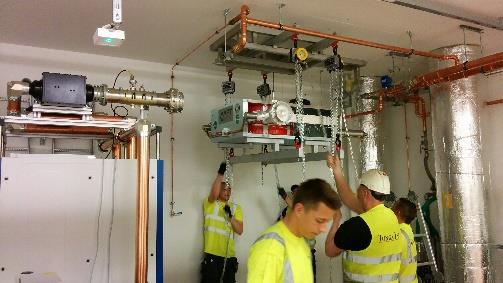
10 Ring RF System - 3 GeV Ring RF The main cavities are placed in the second short straight section of six consecutive achromats. Each RF-room contains two RF power plants. Lars Malmgren, 19th ESLS RF Workshop Lund, 30 Sept. - 1 Oct.,

11 Ring RF System GeV Ring RF Two Main Cavities and two Harmonic Cavities occupy one straight section Two 60 kw Power Plants are placed inside the ring. Lars Malmgren, 19th ESLS RF Workshop Lund, 30 Sept. - 1 Oct.,
 All")

 and four")


12 Ring RF System - Cavities Cavities (100 and 300 MHz) All main cavities including two for Solaris Poland Was Delivered October - December 2013 Eight main (two for Solaris) and four HC has been conditioned at Maxlab. Two main and one HC cavities for the 1.5 GeV remains to be conditioned. April 2013 July2013 Photo: RI Lars Malmgren, 19th ESLS RF Workshop Lund, 30 Sept. - 1 Oct.,
13 Ring RF System Main Cavities The cavities were delivered baked (3 days, 120 degree), with power coupler attached (β = 1). A 600 l/s ion pump is attached. All cavities in the low mbar range. So far, 8 main cavities (6 for MAX-IV, 2 for Solaris) have been conditioned to 25 kw. Prototype: 1 year (!) 2nd Cav # 11: 3.5 months 3rd Cav # 08: 3 months The following 5 cavities: 5 * 1 month (now a computer code was used! Robert Lindvall) When all surrounding systems work OK, 3 weeks of conditioning is sufficient. 1 week up to 50 W (!). Pressure raises up to 5*10-6 mbar! 1 week to pass multipacting regime 3-5 kw. Sometimes a need to attach a turbo! Finally 1 week to reach 25 kw stable operation, without more than 1 glitch per day. Glitch = Sudden high reflected power, however self extinguishing after 60 μs. Lars Malmgren, 19th ESLS RF Workshop Lund, 30 Sept. - 1 Oct.,


14 Ring RF System Harmonic Cavities Multipacting problem origin: Coupler or Cavity body? Lars Malmgren, 19th ESLS RF Workshop Lund, 30 Sept. - 1 Oct.,
15 Ring RF System Main Cavities After conditioning we vented and turned coupler to β = 2. We then measured f r and Q 0 carefully: Achromat # Resonant freq. N2-Vented & Force free [MHz] 100, ,019 99,93 100,13 99, ,042 Difference compared to FAT [MHz] -0,084-0,001 0,014-0,043 0,038 Unloaded Q Theory cyl-symm: Degradation due to Ports & Surfaces [%] 2,1 2,5 2,5 3,2 2,3 5,8 Shunt Impedance (linac def.) [MΩ] 3,45 3,43 3,43 3,41 3,44 3,32 Theory cyl-symm: 3,52 MΩ Required power to reach 300 kv [kw] 26,1 26,2 26,2 26,4 26,2 27,1 Lars Malmgren, 19th ESLS RF Workshop Lund, 30 Sept. - 1 Oct.,


16 Ring RF System Main Cavities A tiny defect in the ceramic window caused a leak p 1*10-8 mbar Lars Malmgren, 19th ESLS RF Workshop Lund, 30 Sept. - 1 Oct.,

17 Ring RF System Main Cavities Three probe loop ceramics (out of 16) have started leaking. Only those we forgot to 50 Ω terminate! Heating problem. Lars Malmgren, 19th ESLS RF Workshop Lund, 30 Sept. - 1 Oct.,
18 Ring RF System Harmonic Cavities The 7 series cavities (5 MAX-IV, 2 Solaris) were delivered non-baked, only leak tested. We performed ourselves the bake-out, with an Århus-coupler at β = 1 attached. Each cavity has two 100 l/s ion pumps. All cavities in the low mbar range. So far, 4 harmonic cavities have been conditioned to 4 kw. Prototype: Is situated in the MAX-III ring since 4 years. Used only at 0.5 kw. The following 4 cavities: 4 * 2 weeks (manual conditioning from a 300 MHz transm. ) 1 week up to 50 W. Pressure raises up to 5*10-7 mbar! 1 week to pass multipacting regime kw. 4 kw without problems, and without glitches. Glitch = Sudden high reflected power, however self extinguishing. Lars Malmgren, 19th ESLS RF Workshop Lund, 30 Sept. - 1 Oct.,
19 Ring RF System Harmonic Cavities After bake-out, conditioning, removal of coupler, and installation we measured f r and Q 0. A Δf r = -140 khz is expected. Achromat # Resonant FAT [MHz] 299,89 299, ,575 Resonant freq. Pumped & Force free [MHz] 299, , ,44 Unloaded Q Theory cyl-symm: Degradation due to Ports & Surfaces [%] 3,95 3,95 3,03 Shunt Impedance (linac def.) [MΩ] 5,32 5,32 5,37 Theory cyl-symm: 5,54 MΩ Lars Malmgren, 19th ESLS RF Workshop Lund, 30 Sept. - 1 Oct.,
.")
 Delivery of high power amplifiers: Two in December 2014 (January 2015) for test of circulators, two in February 2015, two in")
20 Ring RF System High Power Plants Contracts signed for High power amplifiers (Electrosys, Italy). The delivery time was delayed because of severe financial problems in the company. The risk was too large to continue so the contract was canceled (June 2014). A new contract has been signed (September 2014)for delivery of 60 kw liquid cooled solid state power amplifiers ( Rohde & Schwarz, Germany) Circulators (AFT, Germany) Transmission Lines and Integration Work (Exir Boadcasting AB, Sweden) Delivery of high power amplifiers: Two in December 2014 (January 2015) for test of circulators, two in February 2015, two in March and finally two in June 2015 (1.5 GeV). Lars Malmgren, 19th ESLS RF Workshop Lund, 30 Sept. - 1 Oct.,


21 Ring RF System High Power Plants Rohde & Schwarz 60 kw CW solid state liquid cooled amplifiers based on two 30 kw transmitters/amplifiers with additional power combiner >64% overall power efficiency High MTBF Compact: 2000 mm 600 mm 1100 mm (HxWxD) Coolant: glycol/water One pump unit and heat exchanger per rack Image: Electrosys Lars Malmgren, 19th ESLS RF Workshop Lund, 30 Sept. - 1 Oct.,
22 Ring RF System High Power Plants 12 PA units in two racks 5 kw per PA Redundant Liquid cooling system Freq. range from 87.5 MHz to 108 MHz Few changes from off-the-shelf product means lower price Modified from constant output power to constant gain Efficiency values where measured in the FAT: - Overall efficiency at full power 60,2 % - Overall efficiency at -3 db power level 45,3 % With new software with possibility to change the DC voltage of the amplifiers: - Overall efficiency at full power 66,1 % - Overall efficiency at -3 db power level 59,1 % Lars Malmgren, 19th ESLS RF Workshop Lund, 30 Sept. - 1 Oct.,


23 Ring RF System-PA moduls Nominal power 5.0 kw Constant Gain mode Controlled via CAN bus Integrated harmonics filter Voltage 3 x 230 V AC ± 15% / Hz Transistor 50V LDMOS Freescale MRFE6VP61K25H 8 Finale Stage transistors 3 single-phase power supply units 90% of nominal output power with 2 PS Harmonic attenuation up to 1 GHz at Pnom > 85 db Lars Malmgren, 19th ESLS RF Workshop Lund, 30 Sept. - 1 Oct.,


24 High Power RF Systems Installation High Power Amplifiers 120kW Circulators 120 kw 3dB Couplers 6 1/8 EIA Coaxial Lines Lars Malmgren, 19th ESLS RF Workshop Lund, 30 Sept. - 1 Oct.,


25 Ring RF Systems SAT of the High One High Power Amplifier 60 kw to load Power Plants and Circulators Two combined HPAs 120 kw to load 120 kw circulator Port 2 connected to : -50 Ohm water load -EIA 6 1/8 -Short via coax waveguide length 0, 1/8, ¼, 3/8 lambda Lars Malmgren, 19th ESLS RF Workshop Lund, 30 Sept. - 1 Oct.,


26 Ring RF System SAT of Circulators FAT/SAT and retuning of TCU was performed on 8 units Fast RF feedback control Port 2 Mached Load Two test conditions with regards to the termination at port 2: (1) matched water load and (2) short circuit of variable phase. Port 2 Short L=0 Lars Malmgren, 19th ESLS RF Workshop Lund, 30 Sept. - 1 Oct.,


27 Ring RF System SAT of Circulators Fifth circulator in row for test expiried arc att 100kW in configuration to matched load. Circulator returned to AFT Damage is visible at ferrite close to port 1. Bottom side of cooling disc with ferrites shows massive arcing damages. Bottom side of circulator housing shows arc traces on the aluminum surface. Probably very small ferrites chips or local contamination caused arcing at lower power levels already. 1: Remove damaged ferrites, clean cooling disc, replace ferrites by new ones. 2: Clean surface of inner housing. Rework surface of inner housing. 3: Reassembly of Circulator, all mech. & physical testing 4: Electrical retuning of Circulator, TCU calibration Ferrites are damaged severely. Ferrite chips and burning marks close to port 1. Aluminum surface of the house is damaged by arcs. Lars Malmgren, 19th ESLS RF Workshop Lund, 30 Sept. - 1 Oct.,


28 Digital Low Level RF Design by Angela Solom GUI by Antonio Milan The DLLRF is based on the Perseus FPGA platform from Nutaq. Two units is in operation in the 3 GeV ring controlling two cavities each. The third will be taken into operation soon. It is possible to implement two independent loops besides the tuning loop. One controlling the amplitude of the cavity field and one the phase of the forward power. Either I / Q or polar loops can be selected. It has a fast data logger for post-mortem analysis. Lars Malmgren, 19th ESLS RF Workshop Lund, 30 Sept. - 1 Oct.,


29 Chopper for Ring Injection Has two identical vertical kickers. The kickers consist of a 15 cm long stripline pair with a characteristic impedance of 50 Ω for odd TEM modes. Both electrodes are fed by RF An aperture is located downstream. The unwanted bunches will be dumped here. The aperture can be selected so the wanted bunches either passes a 1 mm iris, a 2 mm iris, or over an edge. 10 ns 2 D design If φ 1 =-φ 2 Zo=49.9Ω If φ 1 = 0 Zo=63.8Ω If φ 1 = φ 2 Zo=88.2Ω 333 ps 0.24m 0.84m Aperture Lars Malmgren, 19th ESLS RF Workshop Lund, 30 Sept. - 1 Oct.,

30 Kicker system for ring injection 50 Ω 50 Ω 300 MHz ~400 W 100 MHz ~1 kw 50 Ω Combining network Crosstalk <-31db 100 MHz 300 MHz 700 MHz ~400 W ~1 kw ~300 W 10 ns 333 ps The MAX IV thermionic pre-injector will be covered by the talk of David Olsson Lars Malmgren, 19th ESLS RF Workshop Lund, 30 Sept. - 1 Oct.,
31 Thanks for your attention Questions? Lars Malmgren, 19th ESLS RF Workshop Lund, 30 Sept. - 1 Oct.,
32 No aperture With aperture Lars Malmgren, 19th ESLS RF Workshop Lund, 30 Sept. - 1 Oct.,
FAST RF KICKER DESIGN
 FAST RF KICKER DESIGN David Alesini LNF-INFN, Frascati, Rome, Italy ICFA Mini-Workshop on Deflecting/Crabbing Cavity Applications in Accelerators, Shanghai, April 23-25, 2008 FAST STRIPLINE INJECTION KICKERS
C100 Cryomodule. Seven cell Cavity, 0.7 m long (high Q L ) 8 Cavities per Cryomodule Fits the existing Cryomodule footprint
 8 Cavities per Cryomodule Fits the existing Cryomodule footprint") 1 new module C100 Cryomodule Seven cell Cavity, 0.7 m long (high Q L ) 8 Cavities per Cryomodule Fits the existing Cryomodule footprint Fundamental frequency f 0 Accelerating gradient E acc 1497 MHz >
1 new module C100 Cryomodule Seven cell Cavity, 0.7 m long (high Q L ) 8 Cavities per Cryomodule Fits the existing Cryomodule footprint Fundamental frequency f 0 Accelerating gradient E acc 1497 MHz >
Normal-conducting high-gradient rf systems
 Normal-conducting high-gradient rf systems Introduction Motivation for high gradient Order of 100 GeV/km Operational and state-of-the-art SwissFEL C-band linac: Just under 30 MV/m CLIC prototypes: Over
The HPRF system for a new 6 GeV synchrotron light source in Beijing
 中国科学院高能物理研究所 INSTITUTE OF HIGH ENERGY PHYSICS CHINESE ACADEMY OF SCIENCES The HPRF system for a new 6 GeV synchrotron light source in Beijing (RF group, IHEP) The HEPS HPRF team Power coupler & power source
Detailed Design Report
 Detailed Design Report Chapter 2 MAX IV 3 GeV Storage Ring 2.6. The Radio Frequency System MAX IV Facility CHAPTER 2.6. THE RADIO FREQUENCY SYSTEM 1(15) 2.6. The Radio Frequency System 2.6. The Radio Frequency
Jørgen S. Nielsen Institute for Storage Ring Facilities, Aarhus, University of Aarhus Denmark
 Jørgen S. Nielsen Institute for Storage Ring Facilities, Aarhus, University of Aarhus Denmark What is ISA? ISA operates and develops the storage ring ASTRID and related facilities ISA staff assist internal
10th ESLS RF Meeting September ALBA RF System. F. Perez. on behalf of the ALBA RF Group. ALBA RF System 1/21
 ALBA RF System F. Perez on behalf of the ALBA RF Group ALBA RF System 1/21 Synchrotron Light Source in Cerdanyola (Barcelona, Spain) 3 GeV accelerator 30 beamlines (7 on day one) 50-50 Spanish Government
Commissioning of the ALICE SRF Systems at Daresbury Laboratory Alan Wheelhouse, ASTeC, STFC Daresbury Laboratory ESLS RF 1 st 2 nd October 2008
 Commissioning of the ALICE SRF Systems at Daresbury Laboratory Alan Wheelhouse, ASTeC, STFC Daresbury Laboratory ESLS RF 1 st 2 nd October 2008 Overview ALICE (Accelerators and Lasers In Combined Experiments)
R.Bachimanchi, IPAC, May 2015, Richmond, VA
 1 new module C100 Cryomodule Seven cell Cavity, 0.7 m long (high Q L ) 8 Cavities per Cryomodule Fits the existing Cryomodule footprint Fundamental frequency f 0 Accelerating gradient E acc 1497 MHz >
Status of berlinpro and BESSY II Installation of SSA. Helmholtz-Zentrum Berlin for materials and energy (HZB)
") Status of berlinpro and BESSY II Installation of SSA Wolfgang Anders, Helmholtz-Zentrum Berlin for materials and energy (HZB) 19th ESLS-RF Meeting 30.9.-1.10.2015 MaxLab outline BERLinPro Status building
Status of berlinpro and BESSY II Installation of SSA Wolfgang Anders, Helmholtz-Zentrum Berlin for materials and energy (HZB) 19th ESLS-RF Meeting 30.9.-1.10.2015 MaxLab outline BERLinPro Status building
Low-Level RF. S. Simrock, DESY. MAC mtg, May 05 Stefan Simrock DESY
 Low-Level RF S. Simrock, DESY Outline Scope of LLRF System Work Breakdown for XFEL LLRF Design for the VUV-FEL Cost, Personpower and Schedule RF Systems for XFEL RF Gun Injector 3rd harmonic cavity Main
REVIEW OF HIGH POWER CW COUPLERS FOR SC CAVITIES. S. Belomestnykh
 REVIEW OF HIGH POWER CW COUPLERS FOR SC CAVITIES S. Belomestnykh HPC workshop JLAB, 30 October 2002 Introduction Many aspects of the high-power coupler design, fabrication, preparation, conditioning, integration
RF Design of Normal Conducting Deflecting Cavity
 RF Design of Normal Conducting Deflecting Cavity Valery Dolgashev (SLAC), Geoff Waldschmidt, Ali Nassiri (Argonne National Laboratory, Advanced Photon Source) 48th ICFA Advanced Beam Dynamics Workshop
The BESSY Higher Order Mode Damped Cavity - Further Improvements -
 The BESSY Higher Order Mode Damped Cavity - Further Improvements - Ernst Weihreter Reminder of Technical Problems Solutions Conclusions BESSY HOM Damped Cavity Project collaboration: (EC funded) - BESSY
ESS-Bilbao Contribution to ESS Warm LINAC High Power RF Systems
 ESS-Bilbao Contribution to ESS Warm LINAC High Power RF Systems Arash Kaftoosian RF Group www.essbilbao.org On behalf of: Pedro Gonzalez Ibon Bustinduy RF Project Leader MEBT Project Leader ESS-Bilbao
TESLA RF POWER COUPLERS DEVELOPMENT AT DESY.
 TESLA RF POWER COUPLERS DEVELOPMENT AT DESY. Dwersteg B., Kostin D., Lalayan M., Martens C., Möller W.-D., DESY, D-22603 Hamburg, Germany. Abstract Different RF power couplers for the TESLA Test Facility
2008 JINST 3 S The RF systems and beam feedback. Chapter Introduction
 Chapter 4 The RF systems and beam feedback 4.1 Introduction The injected beam will be captured, accelerated and stored using a 400 MHz superconducting cavity system, and the longitudinal injection errors
HIGH POWER COUPLER FOR THE TESLA TEST FACILITY
 Abstract HIGH POWER COUPLER FOR THE TESLA TEST FACILITY W.-D. Moeller * for the TESLA Collaboration, Deutsches Elektronen-Synchrotron DESY, D-22603 Hamburg, Germany The TeV Energy Superconducting Linear
Project of RF System for 2.2 GeV Electron Storage Ring Zelenograd SR Source.
 Project of RF System for 2.2 GeV Electron Storage Ring Zelenograd SR Source. I.K. Sedlyarov V.S. Arbuzov, E.I Gorniker, A.A. Kondakov, S.A. Krutikhin, G.Ya. Kurkin, I.V.Kuptsov, V.N. Osipov, V.M. Petrov,
Calibrating the Cavity Voltage. Presentation of an idea
 Calibrating the Cavity Voltage. Presentation of an idea Stefan Wilke, DESY MHF-e 21st ESLS rf meeting Kraków, 15th/16th nov 2017 Accelerators at DESY. linear and circular Page 2 Accelerators at DESY. linear
ALICE SRF SYSTEM COMMISSIONING EXPERIENCE A. Wheelhouse ASTeC, STFC Daresbury Laboratory
 ALICE SRF SYSTEM COMMISSIONING EXPERIENCE A. Wheelhouse ASTeC, STFC Daresbury Laboratory ERL 09 8 th 12 th June 2009 ALICE Accelerators and Lasers In Combined Experiments Brief Description ALICE Superconducting
Tutorial on Design of RF system for Indus Accelerator. Maherdra Lad Head, Radio Frequency Systems Division RRCAT, Indore
 Tutorial on Design of RF system for Indus Accelerator Maherdra Lad Head, Radio Frequency Systems Division RRCAT, Indore Basic principle of RF Acceleration RF Power Amplifier The RF source supplies power
INSTALLATION AND FIRST COMMISSIONING OF THE LLRF SYSTEM
 INSTALLATION AND FIRST COMMISSIONING OF THE LLRF SYSTEM FOR THE EUROPEAN XFEL Julien Branlard, for the LLRF team TALK OVERVIEW 2 Introduction Brief reminder about the XFEL LLRF system Commissioning goals
J. Jacob: Status of the ESRF RF upgrade
 17th ESLS RF Meeting 2013 HZB BESSY 18th 19th September Status of the ESRF RF upgrade J. Jacob J.-M. Mercier V. Serrière M. Langlois G. Gautier [CINEL] 1 RF upgrade phase 1 until 2015 - reminder Replacement
MAX II RF system 100 MHz technology Lars Malmgren 10th ESLS RF Meeting Dortmund September 27-28, 2006
 MAX II RF system 1 MHz technology Lars Malmgren 1th ESLS RF Meeting Dortmund September 27-28, 26 Facts and figures MAX-II Frequency [MHz] Harmonic number No of cavity cells No of transmitters Cell radius
Performance of the Prototype NLC RF Phase and Timing Distribution System *
 SLAC PUB 8458 June 2000 Performance of the Prototype NLC RF Phase and Timing Distribution System * Josef Frisch, David G. Brown, Eugene Cisneros Stanford Linear Accelerator Center, Stanford University,
International Technology Recommendation Panel. X-Band Linear Collider Path to the Future. RF System Overview. Chris Adolphsen
 International Technology Recommendation Panel X-Band Linear Collider Path to the Future RF System Overview Chris Adolphsen Stanford Linear Accelerator Center April 26-27, 2004 Delivering the Beam Energy
3 General layout of the XFEL Facility
 3 General layout of the XFEL Facility 3.1 Introduction The present chapter provides an overview of the whole European X-Ray Free-Electron Laser (XFEL) Facility layout, enumerating its main components and
CEBAF Overview June 4, 2010
 CEBAF Overview June 4, 2010 Yan Wang Deputy Group Leader of the Operations Group Outline CEBAF Timeline Machine Overview Injector Linear Accelerators Recirculation Arcs Extraction Systems Beam Specifications
Status of the HOM Damped Cavity Project
 Status of the HOM Damped Cavity Project E. Weihreter / BESSY for the HOM Damped Cavity Collaboration BESSY, Daresbury Lab, DELTA, MaxLab, NTHU Project funded by the EC under contract HPRI-CT-1999-50011
Acceleration of High-Intensity Protons in the J-PARC Synchrotrons. KEK/J-PARC M. Yoshii
 Acceleration of High-Intensity Protons in the J-PARC Synchrotrons KEK/J-PARC M. Yoshii Introduction 1. J-PARC consists of 400 MeV Linac, 3 GeV Rapid Cycling Synchrotron (RCS) and 50 GeV Main synchrotron
Main Injector Cavity Simulation and Optimization for Project X
 Main Injector Cavity Simulation and Optimization for Project X Liling Xiao Advanced Computations Group Beam Physics Department Accelerator Research Division Status Meeting, April 7, 2011 Outline Background
Superconducting RF System. Heung-Sik Kang
 Design of PLS-II Superconducting RF System Heung-Sik Kang On behalf of PLS-II RF group Pohang Accelerator Laboratory Content 1. Introduction 2. Physics design 3. Cryomodules 4. Cryogenic system 5. High
Increasing the Photon Energy for Photonuclear Experiments in MAX-lab by Phase Modulating the SLED Pulse
 Increasing the Photon Energy for Photonuclear Experiments in MAX-lab by Phase Modulating the SLED Pulse Olsson, David; Lilja, Per; Malmgren, Lars 2016 Link to publication Citation for published version
ESRF RF System Status Operation & Upgrade
 14 th ESLS RF Meeting 2010 ELETTRA, 29 th 30 th September ESRF RF System Status Operation & Upgrade Jörn Jacob, ESRF on behalf of the colleagues of the RF Group and many other ESRF Groups 14th ESLS RF,
Advance on High Power Couplers for SC Accelerators
 Advance on High Power Couplers for SC Accelerators Eiji Kako (KEK, Japan) IAS conference at Hong Kong for High Energy Physics, 2017, January 23th Eiji KAKO (KEK, Japan) IAS at Hong Kong, 2017 Jan. 23 1
Linear Particle Accelerator Control Performance
 Linear Particle Accelerator Control Performance 2007 ExpertTune-TiPS Conference April 17-19, 2007 Austin, TX Johnny Tang Overview of the Spallation Neutron Source Accelerator J. Tang 2 Overview of the
Dark current Monitor for the European XFEL D. Lipka, W. Kleen, J. Lund-Nielsen, D. Nölle, S. Vilcins, V. Vogel; DESY Hamburg
 Dark current Monitor for the European XFEL D. Lipka, W. Kleen, J. Lund-Nielsen, D. Nölle, S. Vilcins, V. Vogel; DESY Hamburg Content 2 Dark current Principle of detecting weakly charged bunches with resonator
Circumference 187 m (bending radius = 8.66 m)
") 4. Specifications of the Accelerators Table 1. General parameters of the PF storage ring. Energy 2.5 GeV (max 3.0 GeV) Initial stored current multi-bunch 450 ma (max 500 ma at 2.5GeV) single bunch 70 ma
4. Specifications of the Accelerators Table 1. General parameters of the PF storage ring. Energy 2.5 GeV (max 3.0 GeV) Initial stored current multi-bunch 450 ma (max 500 ma at 2.5GeV) single bunch 70 ma
Jørgen S. Nielsen Center for Storage Ring Facilities (ISA) Aarhus University Denmark. ESLS-RF 22 (8/ ), ASTRID2 RF system 1
 Aarhus University Denmark. ESLS-RF 22 (8/ ), ASTRID2 RF system 1") Jørgen S. Nielsen Center for Storage Ring Facilities (ISA) Aarhus University Denmark ESLS-RF 22 (8/11 2018), ASTRID2 RF system 1 ASTRID2 is the new synchrotron light source in Aarhus, Denmark, since 2013
Jørgen S. Nielsen Center for Storage Ring Facilities (ISA) Aarhus University Denmark ESLS-RF 22 (8/11 2018), ASTRID2 RF system 1 ASTRID2 is the new synchrotron light source in Aarhus, Denmark, since 2013
Design considerations for the RF phase reference distribution system for X-ray FEL and TESLA
 Design considerations for the RF phase reference distribution system for X-ray FEL and TESLA Krzysztof Czuba *a, Henning C. Weddig #b a Institute of Electronic Systems, Warsaw University of Technology,
Status and Plans for the 805 MHz Box Cavity MuCool RF Workshop III 07/07/09 Al Moretti
 Status and Plans for the 805 MHz Box Cavity MuCool RF Workshop III 07/07/09 Al Moretti 7/6/2009 1 Outline : Description of the Box cavity Concept. Box Cavity Summary Plans. HFSS Models of orthogonal and
The transition for the Elettra Input Power Coupler to the standard WR1800
 The transition for the Elettra Input Power Coupler to the standard WR1800 Cristina Pasotti, Mauro Bocciai, Luca Bortolossi, Alessandro Fabris, Marco Ottobretti, Mauro Rinaldi Alessio Turchet Sincrotrone
RF test benches for electron cloud studies
 RF test benches for electron cloud studies Fritz Caspers 1, Ubaldo Iriso Ariz 2, Jean-Michel Laurent 2, Andrea Mostacci 1 1 PS/RF Group, 2 LHC/VAC Group 1. The Traveling Wave multiwire chamber 1.1. Introduction:
Project X Cavity RF and mechanical design. T. Khabiboulline, FNAL/TD/SRF
 Project X Cavity RF and mechanical design T. Khabiboulline, FNAL/TD/SRF TTC meeting on CW-SRF, 2013 Project X Cavity RF and mechanical design T 1 High ß Low ß 0.5 HWR SSR1 SSR2 0 1 10 100 1 10 3 1 10 4
Drive Beam Photo-injector Option for the CTF3 Nominal Phase
 CTF3 Review Drive Beam Photo-injector Option for the CTF3 Nominal Phase Motivation CTF3 Drive Beam Requirements CTF3 RF gun design The Laser (I. Ross / RAL) The Photocathode Cost estimate Possible schedule
Superconducting RF cavities activities for the MAX project
 1 Superconducting RF cavities activities for the MAX project OECD-NEA TCADS-2 Workshop Nantes, 22 May 2013 Marouan El Yakoubi, CNRS / IPNO 2 Contents 352 MHz spoke Cryomodule design 700 MHz test area 700
FLASH at DESY. FLASH. Free-Electron Laser in Hamburg. The first soft X-ray FEL operating two undulator beamlines simultaneously
 FLASH at DESY The first soft X-ray FEL operating two undulator beamlines simultaneously Katja Honkavaara, DESY for the FLASH team FEL Conference 2014, Basel 25-29 August, 2014 First Lasing FLASH2 > First
REVIEW OF FAST BEAM CHOPPING F. Caspers CERN AB-RF-FB
 F. Caspers CERN AB-RF-FB Introduction Review of several fast chopping systems ESS-RAL LANL-SNS JAERI CERN-SPL Discussion Conclusion 1 Introduction Beam choppers are typically used for β = v/c values between
LHC TRANSVERSE FEEDBACK SYSTEM: FIRST RESULTS OF COMMISSIONING. V.M. Zhabitsky XXI Russian Particle Accelerator Conference
 LHC TRANSVERSE FEEDBACK SYSTEM: FIRST RESULTS OF COMMISSIONING V.M. Zhabitsky XXI Russian Particle Accelerator Conference 28.09-03.10.2008, Zvenigorod LHC Transverse Feedback System: First Results of Commissioning
Progresses on China ADS Superconducting Cavities
 Progresses on China ADS Superconducting Cavities Peng Sha IHEP, CAS 2013/06/12 1 Outline 1. Introduction 2. Spoke012 cavity 3. Spoke021 cavity 4. Spoke040 cavity 5. 650MHz β=0.82 5-cell cavity 6. High
Coupler Electromagnetic Design
 Coupler Electromagnetic Design HPC Workshop, TJNAF October 30 November 1, 2002 Yoon Kang Spallation Neutron Source Oak Ridge National Laboratory Contents Fundamental Power Coupler Design Consideration
780-8 Series Constant Impedance FM Combiners
 Features Cylindrical construction provides better mechanical and electrical stability than square or rectangular cavities Factory tuned to customer s specified channel, yet can be easily field converted
New Tracking Gantry-Synchrotron Idea. G H Rees, ASTeC, RAL, U.K,
 New Tracking Gantry-Synchrotron Idea G H Rees, ASTeC, RAL, U.K, Scheme makes use of the following: simple synchrotron and gantry magnet lattices series connection of magnets for 5 Hz tracking one main
Physics Requirements Document Document Title: SCRF 1.3 GHz Cryomodule Document Number: LCLSII-4.1-PR-0146-R0 Page 1 of 7
 Document Number: LCLSII-4.1-PR-0146-R0 Page 1 of 7 Document Approval: Originator: Tor Raubenheimer, Physics Support Lead Date Approved Approver: Marc Ross, Cryogenic System Manager Approver: Jose Chan,
Manufacturers of RF and Microwave Components and Assemblies Specialist in RF Filters, Power amplifiers and RF Switches
 Manufacturers of RF and Microwave Components and Assemblies Specialist in RF Filters, Power amplifiers and RF Switches sales@cormic.com www.cormic.com P 724.940.7556 F 724.940.7707 RF & MICROWAVE FILTERS
HIGH POWER INPUT COUPLERS FOR THE STF BASELINE CAVITY SYSTEM AT KEK
 HIGH POWER INPUT COUPLERS FOR THE STF BASELINE CAVITY SYSTEM AT KEK E. Kako #, H. Hayano, S. Noguchi, T. Shishido, K. Watanabe and Y. Yamamoto KEK, Tsukuba, Ibaraki, 305-0801, Japan Abstract An input coupler,
Fast Kickers at DESY
 Fast Kickers at DESY Injection / ejection in a TESLA like DR Generation of a pulse with a pulse length of 12ns Measurement at TTF 2 Full power test Measurements at ATF XFEL activity Talk given by Hans
Beam Diagnostics, Low Level RF and Feedback for Room Temperature FELs. Josef Frisch Pohang, March 14, 2011
 Beam Diagnostics, Low Level RF and Feedback for Room Temperature FELs Josef Frisch Pohang, March 14, 2011 Room Temperature / Superconducting Very different pulse structures RT: single bunch or short bursts
MICROWAVE MICROWAVE TRAINING BENCH COMPONENT SPECIFICATIONS:
 Microwave section consists of Basic Microwave Training Bench, Advance Microwave Training Bench and Microwave Communication Training System. Microwave Training System is used to study all the concepts of
Uppsala, June 17 th - 19 th, 2013
 TIARA Workshop on RF Power Generation for Accelerators Uppsala, June 17 th - 19 th, 2013 Massamba DIOP, R. LOPES, P. MARCHAND, F. RIBEIRO SSA operation at SOLEIL BOOSTER 35 kw STORAGE RING 180 kw SOLEIL
Engineering Challenges and Solutions for MeRHIC. Andrew Burrill for the MeRHIC Team
 Engineering Challenges and Solutions for MeRHIC Andrew Burrill for the MeRHIC Team Key Components Photoinjector Design Photocathodes & Drive Laser Linac Cavities 703.75 MHz 5 cell cavities 3 rd Harmonic
Yongming Li Institute of modern physics 31/07/2017
 Yongming Li Institute of modern physics 31/07/2017 2 Outline Motivation Coupler Design Operation Feedback Summary Project HIAF (2017-2024) SRing SRing: Spectrometer ring Circumference:290m Rigidity: 13Tm
Maurizio Vretenar Linac4 Project Leader EuCARD-2 Coordinator
 Maurizio Vretenar Linac4 Project Leader EuCARD-2 Coordinator Every accelerator needs a linac as injector to pass the region where the velocity of the particles increases with energy. At high energies (relativity)
ECRH on the Levitated Dipole Experiment
 ECRH on the Levitated Dipole Experiment S. Mahar, J. Kesner, A.C. Boxer, J.E. Ellsworth, I. Karim, A. Roach MIT PSFC A.K. Hansen, D.T. Garnier, M.E. Mauel, E.E.Ortiz Columbia University Presented at the
Does the short pulse mode need energy recovery?
 Does the short pulse mode need energy recovery? Rep. rate Beam power @ 5GeV 1nC @ 100MHz 500MW Absolutely 1nC @ 10MHz 1nC @ 1MHz 50MW 5MW Maybe 1nC @ 100kHz 0.5MW No Most applications we have heard about
THE ORION PHOTOINJECTOR: STATUS and RESULTS
 THE ORION PHOTOINJECTOR: STATUS and RESULTS Dennis T. Palmer SLAC / ARDB ICFA Sardinia 4 July 2002 1. Introduction 2. Beam Dynamics Simulations 3. Photoinjector 1. RF Gun 2. Solenoidal Magnet 3. Diagnostics
MEASURES TO REDUCE THE IMPEDANCE OF PARASITIC RESONANT MODES IN THE DAΦNE VACUUM CHAMBER
 Frascati Physics Series Vol. X (1998), pp. 371-378 14 th Advanced ICFA Beam Dynamics Workshop, Frascati, Oct. 20-25, 1997 MEASURES TO REDUCE THE IMPEDANCE OF PARASITIC RESONANT MODES IN THE DAΦNE VACUUM
Grounding for EMC at the European XFEL
 Grounding for EMC at the European XFEL Herbert Kapitza, Hans-Jörg Eckoldt, Markus Faesing Deutsches Elektronensynchrotron (DESY) D-22603 Hamburg, Germany Email: herbert.kapitza@desy.de Abstract The European
Bioimaging of cells and tissues using accelerator-based sources
 Analytical and Bioanalytical Chemistry Electronic Supplementary Material Bioimaging of cells and tissues using accelerator-based sources Cyril Petibois, Mariangela Cestelli Guidi Main features of Free
 TitleThe RF Power Amplifier System for a Author(s) Fujisawa, Hiroshi Citation Bulletin of the Institute for Chemi University (1991), 69(1): 11-14 Issue Date 1991-03-30 URL http://hdl.handle.net/2433/77367
Advanced Photon Source Monopulse rf Beam Position Monitor Front-End Upgrade*
 Advanced Phon Source Monopulse rf Beam Position Monir Front-End Upgrade* Robert M. Lill and Glenn A. Decker Advanced Phon Source, Argonne National Laborary 9700 South Cass Avenue, Argonne, Illinois 60439
Lawrence Berkeley Laboratory UNIVERSITY OF CALIFORNIA
 d e Lawrence Berkeley Laboratory UNIVERSITY OF CALIFORNIA Accelerator & Fusion Research Division I # RECEIVED Presented at the International Workshop on Collective Effects and Impedance for B-Factories,
CEBAF waveguide absorbers. R. Rimmer for JLab SRF Institute
 CEBAF waveguide absorbers R. Rimmer for JLab SRF Institute Outline Original CEBAF HOM absorbers Modified CEBAF loads for FEL New materials for replacement loads High power loads for next generation FELs
The European Spallation Source. Dave McGinnis Chief Engineer ESS\Accelerator Division IVEC 2013
 The European Spallation Source Dave McGinnis Chief Engineer ESS\Accelerator Division IVEC 2013 Overview The European Spallation Source (ESS) will house the most powerful proton linac ever built. The average
Design of the magnets for the MAX IV project. Martin Johansson, Beam Dynamics meets Magnets-II workshop, Bad Zurzach, Dec.
 Design of the magnets for the MAX IV project Martin Johansson, Beam Dynamics meets Magnets-II workshop, Bad Zurzach, 01-04 Dec. 2014 MAX IV 3 GeV ring magnets key aspects: Relatively small magnet aperture
The VARIAN 250 MeV Superconducting Compact Proton Cyclotron
 The VARIAN 250 MeV Superconducting Compact Proton Cyclotron VARIAN Medical Systems Particle Therapy GmbH Friedrich-Ebert-Str. 1 D-51429 BERGISCH GLADBACH GERMANY OUTLINE 1. Why having a Superconducting
Gyroklystron Research at CCR
 Gyroklystron Research at CCR RLI@calcreek.com Lawrence Ives, Michael Read, Jeff Neilson, Philipp Borchard and Max Mizuhara Calabazas Creek Research, Inc. 20937 Comer Drive, Saratoga, CA 95070-3753 W. Lawson
Bunch-by-Bunch Broadband Feedback for the ESRF
 Bunch-by-Bunch Broadband Feedback for the ESRF ESLS RF meeting / Aarhus 21-09-2005 J. Jacob, E. Plouviez, J.-M. Koch, G. Naylor, V. Serrière Goal: Active damping of longitudinal and transverse multibunch
Current Industrial SRF Capabilities and Future Plans
 and Future Plans Capabilities in view of Design Engineering Manufacturing Preparation Testing Assembly Taking into operation Future Plans Participate in and contribute to development issues, provide prototypes
Automatic phase calibration for RF cavities using beam-loading signals. Jonathan Edelen LLRF 2017 Workshop (Barcelona) 18 Oct 2017
 18 Oct 2017") Automatic phase calibration for RF cavities using beam-loading signals Jonathan Edelen LLRF 2017 Workshop (Barcelona) 18 Oct 2017 Introduction How do we meet 10-4 energy stability for PIP-II? 2 11/9/2017
Automatic phase calibration for RF cavities using beam-loading signals Jonathan Edelen LLRF 2017 Workshop (Barcelona) 18 Oct 2017 Introduction How do we meet 10-4 energy stability for PIP-II? 2 11/9/2017
RF power tests of LEP2 main couplers on a single cell superconducting cavity
 RF power tests of LEP2 main couplers on a single cell superconducting cavity H.P. Kindermann, M. Stirbet* CERN, CH-1211 Geneva 23, Switzerland Abstract To determine the power capability of the input couplers
Status of the European XFEL Accelerator Construction Project. Reinhard Brinkmann, DESY
 Status of the European XFEL Accelerator Construction Project Reinhard Brinkmann, DESY European XFEL Introduction Some specifications Photon energy 0.3-24 kev Pulse duration ~ 10-100 fs Pulse energy few
Joachim Tückmantel CERN, Geneva
 Joachim Tückmantel CERN, Geneva Split up the problem : Linac made of different sections Section made of equivalent families Joachim Tückmantel, CERN Family: One transmitter supplies several (or 1) cavities
Pulsed 5 MeV standing wave electron linac for radiation processing
 PHYSICAL REVIEW SPECIAL TOPICS - ACCELERATORS AND BEAMS, VOLUME 7, 030101 (2004) Pulsed 5 MeV standing wave electron linac for radiation processing L. Auditore, R. C. Barnà, D. De Pasquale, A. Italiano,
Accelerator Complex U70 of IHEP-Protvino: Status and Upgrade Plans
 INSTITUTE FOR HIGH ENERGY PHYSICS () Protvino, Moscow Region, 142281, Russia Accelerator Complex U70 of -Protvino: Status and Upgrade Plans (report 4.1-1) Sergey Ivanov, on behalf of the U70 staff September
A Design Study of a 100-MHz Thermionic RF Gun for the ANL XFEL-O Injector
 A Design Study of a 100-MHz Thermionic RF Gun for the ANL XFEL-O Injector A. Nassiri Advanced Photon Source For ANL XFEL-O Injector Study Group M. Borland (ASD), B. Brajuskovic (AES), D. Capatina (AES),
High acceleration gradient. Critical applications: Linear colliders e.g. ILC X-ray FELs e.g. DESY XFEL
 High acceleration gradient Critical applications: Linear colliders e.g. ILC X-ray FELs e.g. DESY XFEL Critical points The physical limitation of a SC resonator is given by the requirement that the RF magnetic
BESSY VSR: SRF challenges and developments for a variable pulse-length next generation light source
 BESSY VSR: SRF challenges and developments for a variable pulse-length next generation light source Institut SRF - Wissenschaft und Technologie (FG-ISRF) Adolfo Vélez et al. SRF17 Lanzhou, 17-21/7/2017
LEP Couplers..a Troubled Story of a Success. HPC2002, Jefferson Lab, October 30 th, 2002 R. Losito, CERN 1
 LEP Couplers..a Troubled Story of a Success HPC2002, Jefferson Lab, October 30 th, 2002 R. Losito, CERN 1 1 Overview & development: specifications, problems, solutions Operation: field equalization, trip
Development of a 20-MeV Dielectric-Loaded Accelerator Test Facility
 SLAC-PUB-11299 Development of a 20-MeV Dielectric-Loaded Accelerator Test Facility S.H. Gold, et al. Contributed to 11th Advanced Accelerator Concepts Workshop (AAC 2004), 06/21/2004--6/26/2004, Stony
NEW MATERIALS AND DESIGNS FOR HIGH-POWER, FAST PHASE SHIFTERS
 NEW MATERIALS AND DESIGNS FOR HIGH-POWER, FAST PHASE SHIFTERS R. Madrak, D. Sun, D. Wildman, FNAL, Batavia, IL, 60510, U.S.A. E. Cherbak, D. Horan, ANL, Argonne, IL 60439, U.S.A. Abstract In the 100 MeV
System Integration of the TPS. J.R. Chen NSRRC, Hsinchu
 System Integration of the TPS J.R. Chen NSRRC, Hsinchu OUTLINE I. Main features of the TPS II. Major concerns and intersystem effects of an advanced synchrotron light source III. Subsystems and intersystem
High Gradient Studies at the NLC Test Accelerator (NLCTA)
") Chris Adolphsen High Gradient Studies at the NLC Test Accelerator (NLCTA) NLCTA Linac RF Unit (One of Two) Contributors C. Adolphsen, G. Bowden, D. Burke, J. Cornuelle, S. Dobert, V. Dolgashev, J. Frisch,
Chris Adolphsen High Gradient Studies at the NLC Test Accelerator (NLCTA) NLCTA Linac RF Unit (One of Two) Contributors C. Adolphsen, G. Bowden, D. Burke, J. Cornuelle, S. Dobert, V. Dolgashev, J. Frisch,
Dark Current Kicker Studies at FLASH
 Dark Current Kicker Studies at FLASH F. Obier, J. Wortmann, S. Schreiber, W. Decking, K. Flöttmann FLASH Seminar, DESY, 02 Feb 2010 History of the dark current kicker 2005 Vertical kicker was installed
EMMA the World's First Non-Scaling FFAG Accelerator
 EMMA the World's First Non-Scaling FFAG Accelerator Susan Smith STFC Daresbury Laboratory CONTENTS Introduction Contents What are ns-ffags? and Why EMMA? The international collaboration EMMA goals and
Thermionic Bunched Electron Sources for High-Energy Electron Cooling
 Thermionic Bunched Electron Sources for High-Energy Electron Cooling Vadim Jabotinski 1, Yaroslav Derbenev 2, and Philippe Piot 3 1 Institute for Physics and Technology (Alexandria, VA) 2 Thomas Jefferson
1.5 GHz Cavity design for the Clic Damping Ring and as Active Third Harmonic cavity for ALBA.
 1 1.5 GHz Cavity design for the Clic Damping Ring and as Active Third Harmonic cavity for ALBA. Beatriz Bravo Overview 2 1.Introduction 2.Active operation 3.Electromagnetic design 4.Mechanical design Introduction
DEVELOPMENT OF A DLLRF USING COMERCIAL UTCA PLATFORM
 ACDIV-2017-11 May 2017 DEVELOPMENT OF A DLLRF USING COMERCIAL UTCA PLATFORM A. Salom, E. Morales, F. Pérez - ALBA Synchrotron Abstract The Digital LLRF of ALBA has been implemented using commercial cpci
FAST KICKERS LNF-INFN
 ILC Damping Rings R&D Workshop - ILCDR06 September 26-28, 2006 at Cornell University FAST KICKERS R&D @ LNF-INFN Fabio Marcellini for the LNF fast kickers study group* * D. Alesini, F. Marcellini P. Raimondi,