KNIFE-EDGE RIGHT-ANGLE PRISM MIRRORS
|
|
|
- Roderick Harper
- 5 years ago
- Views:
Transcription


 Dielectric Coatings (400 nm - 1100 nm) Laser Line (532 and 1064 nm) Knife Edge (250 nm - 20 µm) range, or a")

1 KNIFE-EDGE RIGHT-ANGLE PRISM MIRRORS Precision Cut Prisms Feature Bevel-Free 90 Angle Dielectric, Silver, Gold, and Aluminum Coatings Available 25 mm x 25 mm Faces Application Idea MRAK25-M01 Mounted on a KM100B Kinematic Platform Mount MRAK25-F01 MRAK25-E02 OVERVIEW Features Right-Angle Prism with Mirror-Coated Legs "Knife Edge" Between the Two Coated Surfaces for Combining or Separating Beams 25 mm x 25 mm Reflective Surfaces Thorlabs' Knife-Edge Right-Angle Prism Mirrors feature reflective coatings on the two legs and offer a clear aperture extending across the 90 angle between the coated surfaces. They are manufactured from N-BK7 and have 25 mm x 25 mm reflective legs. These prism mirrors are offered with one of the following reflective coatings: UV enhanced aluminum, protected aluminum, protected gold, protected silver, a broadband dielectric coating for the nm Right Angle Prism Mirror Selection Guide Metallic Coatings (250 nm - 20 µm) Dielectric Coatings (400 nm nm) Laser Line (532 and 1064 nm) Knife Edge (250 nm - 20 µm) range, or a broadband dielectric coating for the nm range. Please see the Specs and Graphs tabs above for details on the reflectivity of the various coatings. The precision corner between the two coated surfaces allows two counterpropagating beams to be made collinear with the output orthogonal to the input, as shown in the figure to the left. They can also be used to split a single input beam aimed directly at the knife edge. The prisms are ideal for situations where it is undesirable to use a beamsplitting cube, such as due to the geometry of the setup. Some diffraction and scatter will occur whenever a beam is split using these prisms. These prisms feature a coating that extends to the edge of the optic. Care should be used when handling the prisms, as the coated edge is very delicate and can be chipped easily. While the hypotenuse is polished, these mirrors are not intended for use as retroreflectors due to the adhesion layers used in the coating process. As a result, no specifications are given for the polished hypotenuse of the prism. For retroreflection applications we suggest the PS911K, an uncoated version of our knife edge prism, or our selection of mounted and unmounted retroreflectors. Thorlabs also offers a selection of hypotenuse-coated right-angle prism mirrors. SPECS
2 Item # MRAK25-F01 MRAK25-G01 MRAK25-P01 Coating (On Legs) UV Enhanced Aluminum Protected Aluminum Protected Silver Reflectivity a R avg > 90% ( nm) R avg > 90% ( nm) R avg > 95% (2-20 µm) R avg > 97% ( nm) R avg > 96% (2-20 µm) L b 25.0 mm X b 35.4 mm Clear Aperture (Coated Surfaces) Clear Aperture (Hypotenuse) Surface Flatness (All Surfaces) Surface Quality Entire Face Length and Width, Excluding a 1.25 mm Border Along All Beveled Edges 90% of Face Length and Width nm Over the Clear Aperture Scratch-Dig Damage Threshold Pulse CW c 0.3 J/cm 2 at 355 nm, 10 ns, 10 Hz, Ø0.381 mm 300 W/cm at µm, Ø0.044 mm 500 W/cm at 10.6 µm, Ø0.339 mm 0.3 J/cm 2 at 1064 nm, 10 ns, 10 Hz, Ø1.000 mm 60 W/cm at µm, Ø0.044 mm 350 W/cm at 10.6 µm, Ø0.339 mm 3 J/cm 2 at 1064 nm, 10 ns, 10 Hz, Ø1.000 mm 1750 W/cm at µm, Ø0.044 mm 1500 W/cm at 10.6 µm, Ø0.339 mm Item # MRAK25-M01 MRAK25-E02 MRAK25-E03 Coating (On Legs) Protected Gold Broadband Dielectric Broadband Dielectric Reflectivity a R avg > 96% (800 nm - 20 µm) R s and R p > 99% ( nm) R s and R p > 99% ( nm) L b 25.0 mm X b 35.4 mm Clear Aperture (Coated Surfaces) Clear Aperture (Hypotenuse) Surface Flatness (All Surfaces) Surface Quality Entire Face Length and Width, Excluding a 1.25 mm Border Along All Beveled Edges 90% of Face Length and Width nm Over the Clear Aperture Scratch-Dig Damage Threshold Pulse 2 J/cm 2 at 1064 nm, 10 ns, 10 Hz, Ø1.000 mm 0.25 J/cm 2 at 532 nm, 10 ns, 10 Hz, Ø0.803 mm 1.0 J/cm 2 at 810 nm, 10 ns, 10 Hz, Ø0.133 mm 0.5 J/cm 2 at 1064 nm, 10 ns, 10 Hz, Ø0.433 mm CW c 1500 W/cm at µm, Ø0.044 mm 750 W/cm at 10.6 µm, Ø0.339 mm - - For an angle of incidence from 0 to 45. Defined in the diagram below. The power density of your beam should be calculated in terms of W/cm. For an explanation of why the linear power density provides the best metric for long pulse and CW sources, please see the Damage Thresholds tab. GRAPHS All data shown below is for unpolarized light, unless otherwise stated. The shaded regions in the graphs denote the ranges over which we guarantee the specified reflectance. Please note that the reflectance outside of these bands is typical and can vary from lot to lot, especially in out-of-band regions where the reflectance is fluctuating or sloped. UV-Enhanced Aluminum Coating ( nm)
 Excel")


 Excel Spreadsheet with Raw")


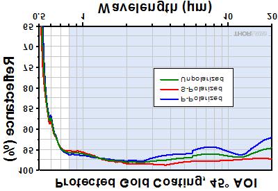
3 Excel Spreadsheet with Raw Data for UV-Enhanced Aluminum Excel Spreadsheet with Raw Data for UV-Enhanced Aluminum Excel Spreadsheet with Raw Data for UV-Enhanced Aluminum Excel Spreadsheet with Raw Data for UV-Enhanced Aluminum Protected Aluminum Coating (450 nm - 20 µm) Excel Spreadsheet with Raw Data for Protected Aluminum Excel Spreadsheet with Raw Data for Protected Aluminum Protected Silver Coating (450 nm - 20 µm) Excel Spreadsheet with Raw Data for Protected Silver Excel Spreadsheet with Raw Data for Protected Silver Protected Gold Coating (800 nm - 20 µm) Excel Spreadsheet with Raw Data for Protected Gold Excel Spreadsheet with Raw Data for Protected Gold These plots show the reflectivity of our -E02 ( nm) and -E03 ( nm) dielectric coatings for a typical coating run. The shaded region in each graph denotes the spectral range over which the coating is highly reflective. Due to variations in each run, this recommended spectral range is narrower than the actual range over which the optic will be highly reflective. If you have any concerns about the interpretation of this data, please contact Tech Support. For
 Excel Spreadsheet with Raw Data for -E02 Coating, 8 and 45 AOI -E03 Coating (750-1100 nm) Excel Spreadsheet with Raw Data for -E03 Coating, 8 and 45 AOI DAMAGE THRESHOLDS")

 0.3 J/cm 2 at 1064 nm, 10 ns, 10 Hz, Ø1.000 mm -G01 (CW) a 60 W/cm at 1.064 µm, Ø0.044 mm 350 W/cm at 10.6 µm, Ø0.339 mm -P01 (Pulse) 3 J/cm 2 at 1064 nm, 10 ns, 10 Hz, Ø1.")

4 applications that require a mirror that bridges the spectral range between the dielectric coatings, please consider a metallic mirror. -E02 Coating ( nm) Excel Spreadsheet with Raw Data for -E02 Coating, 8 and 45 AOI -E03 Coating ( nm) Excel Spreadsheet with Raw Data for -E03 Coating, 8 and 45 AOI DAMAGE THRESHOLDS Damage Threshold Data for Thorlabs' Knife- Edge Right-Angle Prism Mirrors The specifications to the right are measured data for Thorlabs' knife-edge prism mirrors. Damage threshold specifications are constant for a given coating type, regardless of the size of the mirror. Damage Threshold Specifications Coating Designation (Item # Suffix) Damage Threshold -F01 (Pulse) 0.3 J/cm 2 at 355 nm, 10 ns, 10 Hz, Ø0.381 mm -F01 (CW) a 300 W/cm at µm, Ø0.044 mm 500 W/cm at 10.6 µm, Ø0.339 mm -G01 (Pulse) 0.3 J/cm 2 at 1064 nm, 10 ns, 10 Hz, Ø1.000 mm -G01 (CW) a 60 W/cm at µm, Ø0.044 mm 350 W/cm at 10.6 µm, Ø0.339 mm -P01 (Pulse) 3 J/cm 2 at 1064 nm, 10 ns, 10 Hz, Ø1.000 mm -P01 (CW) a 1750 W/cm at µm, Ø0.044 mm 1500 W/cm at 10.6 µm, Ø0.339 mm -M01 (Pulse) 2 J/cm 2 at 1064 nm, 10 ns, 10 Hz, Ø1.000 mm -M01 (CW) a 1500 W/cm at µm, Ø0.044 mm 750 W/cm at 10.6 µm, Ø0.339 mm -E J/cm 2 at 532 nm, 10 ns, 10 Hz, Ø0.803 mm -E03 1 J/cm 2 at 810 nm, 10 ns, 10 Hz, Ø0.133 mm 0.5 J/cm 2 at 1064 nm, 10 ns, 10 Hz, Ø0.433 mm The power density of your beam should be calculated in terms of W/cm. For an explanation of why the linear power density provides the best metric for long pulse and CW sources, please see the "Continuous Wave and Long-Pulse Lasers" section below. Laser Induced Damage Threshold Tutorial The following is a general overview of how laser induced damage thresholds are measured and how the values may be utilized in determining the appropriateness of an optic for a given application. When choosing optics, it is important to understand the Laser Induced Damage Threshold (LIDT) of the optics being used. The LIDT for an optic greatly depends on the type of laser you are using. Continuous wave (CW) lasers typically cause damage from thermal effects (absorption either in the coating or in the substrate). Pulsed lasers, on the other hand, often strip electrons from the lattice structure of an optic before causing thermal damage. Note that the guideline presented here assumes room temperature operation and optics in new condition (i.e., within scratchdig spec, surface free of contamination, etc.). Because dust or other particles on the surface of an optic can cause damage at lower thresholds, we recommend keeping surfaces clean and free of debris. For more information on cleaning optics, please see our Optics Cleaning tutorial.
 or for a number of pulses (pulse repetition frequency specified).")

5 Testing Method Thorlabs' LIDT testing is done in compliance with ISO/DIS11254 and ISO specifications. First, a low-power/energy beam is directed to the optic under test. The optic is exposed in 10 locations to this laser beam for 30 seconds (CW) or for a number of pulses (pulse repetition frequency specified). After exposure, the optic is examined by a microscope (~100X magnification) for any visible damage. The number of locations that are damaged at a particular power/energy level is recorded. Next, the power/energy is either increased or decreased and the optic is exposed at 10 new locations. This process is repeated until damage is observed. The damage threshold is then assigned to be the highest power/energy that the optic can withstand without causing damage. A histogram such as that below represents the testing of one BB1-E02 mirror. The photograph above is a protected aluminumcoated mirror after LIDT testing. In this particular test, it handled 0.43 J/cm 2 (1064 nm, 10 ns pulse, 10 Hz, Ø1.000 mm) before damage. According to the test, the damage threshold of the mirror was 2.00 J/cm 2 (532 nm, 10 ns pulse, 10 Hz, Ø0.803 mm). Please keep in mind that these tests are performed on clean optics, as dirt and contamination can significantly lower the damage threshold of a component. While the test results are only representative of one coating run, Thorlabs specifies damage threshold values that account for coating variances. Continuous Wave and Long-Pulse Lasers Fluence # of Tested Locations Example Test Data Locations with Damage Locations Without Damage 1.50 J/cm J/cm J/cm J/cm J/cm When an optic is damaged by a continuous wave (CW) laser, it is usually due to 5.00 J/cm the melting of the surface as a result of absorbing the laser's energy or damage to the optical coating (antireflection) [1]. Pulsed lasers with pulse lengths longer than 1 µs can be treated as CW lasers for LIDT discussions. When pulse lengths are between 1 ns and 1 µs, laser-induced damage can occur either because of absorption or a dielectric breakdown (therefore, a user must check both CW and pulsed LIDT). Absorption is either due to an intrinsic property of the optic or due to surface irregularities; thus LIDT values are only valid for optics meeting or exceeding the surface quality specifications given by a manufacturer. While many optics can handle high power CW lasers, cemented (e.g., achromatic doublets) or highly absorptive (e.g., ND filters) optics tend to have lower CW damage thresholds. These lower thresholds are due to absorption or scattering in the cement or metal coating. Pulsed lasers with high pulse repetition frequencies (PRF) may behave similarly to CW beams. Unfortunately, this is highly dependent on factors such as absorption and thermal diffusivity, so there is no reliable method for determining when a high PRF laser will damage an optic due to thermal effects. For beams with a high PRF both the average and peak powers must be compared to the equivalent CW power. Additionally, for highly transparent materials, there is little to no drop in the LIDT with increasing PRF. In order to use the specified CW damage threshold of an optic, it is necessary to know the following: 1. Wavelength of your laser 2. Beam diameter of your beam (1/e 2 ) 3. Approximate intensity profile of your beam (e.g., Gaussian) 4. Linear power density of your beam (total power divided by 1/e 2 beam diameter) LIDT in linear power density vs. pulse length and spot size. For long pulses to CW, linear power density becomes a constant with spot size. This graph was obtained from [1]. Thorlabs expresses LIDT for CW lasers as a linear power density measured in W/cm. In this regime, the LIDT given as a linear power density can be applied to any beam diameter; one does not need to compute an adjusted LIDT to adjust for changes in spot size, as demonstrated by the graph to the right. Average linear power density can be calculated using the equation below. The calculation above assumes a uniform beam intensity profile. You must now consider
6 hotspots in the beam or other non-uniform intensity profiles and roughly calculate a maximum power density. For reference, a Gaussian beam typically has a maximum power density that is twice that of the uniform beam (see lower right). Now compare the maximum power density to that which is specified as the LIDT for the optic. If the optic was tested at a wavelength other than your operating wavelength, the damage threshold must be scaled appropriately. A good rule of thumb is that the damage threshold has a linear relationship with wavelength such that as you move to shorter wavelengths, the damage threshold decreases (i.e., a LIDT of 10 W/cm at 1310 nm scales to 5 W/cm at 655 nm): While this rule of thumb provides a general trend, it is not a quantitative analysis of LIDT vs wavelength. In CW applications, for instance, damage scales more strongly with absorption in the coating and substrate, which does not necessarily scale well with wavelength. While the above procedure provides a good rule of thumb for LIDT values, please contact Tech Support if your wavelength is different from the specified LIDT wavelength. If your power density is less than the adjusted LIDT of the optic, then the optic should work for your application. Please note that we have a buffer built in between the specified damage thresholds online and the tests which we have done, which accommodates variation between batches. Upon request, we can provide individual test information and a testing certificate. The damage analysis will be carried out on a similar optic (customer's optic will not be damaged). Testing may result in additional costs or lead times. Contact Tech Support for more information. Pulsed Lasers As previously stated, pulsed lasers typically induce a different type of damage to the optic than CW lasers. Pulsed lasers often do not heat the optic enough to damage it; instead, pulsed lasers produce strong electric fields capable of inducing dielectric breakdown in the material. Unfortunately, it can be very difficult to compare the LIDT specification of an optic to your laser. There are multiple regimes in which a pulsed laser can damage an optic and this is based on the laser's pulse length. The highlighted columns in the table below outline the relevant pulse lengths for our specified LIDT values. Pulses shorter than 10-9 s cannot be compared to our specified LIDT values with much reliability. In this ultra-short-pulse regime various mechanics, such as multiphoton-avalanche ionization, take over as the predominate damage mechanism [2]. In contrast, pulses between 10-7 s and 10-4 s may cause damage to an optic either because of dielectric breakdown or thermal effects. This means that both CW and pulsed damage thresholds must be compared to the laser beam to determine whether the optic is suitable for your application. Pulse Duration t < 10-9 s 10-9 < t < 10-7 s 10-7 < t < 10-4 s t > 10-4 s Damage Mechanism Avalanche Ionization Dielectric Breakdown Dielectric Breakdown or Thermal Thermal Relevant Damage Specification No Comparison (See Above) Pulsed Pulsed and CW CW When comparing an LIDT specified for a pulsed laser to your laser, it is essential to know the following: 1. Wavelength of your laser 2. Energy density of your beam (total energy divided by 1/e 2 area) 3. Pulse length of your laser 4. Pulse repetition frequency (prf) of your laser 5. Beam diameter of your laser (1/e 2 ) 6. Approximate intensity profile of your beam (e.g., Gaussian) The energy density of your beam should be calculated in terms of J/cm 2. The graph to the right shows why expressing the LIDT as an energy density provides the best metric for short pulse sources. In this regime, the LIDT given as an energy density can be applied to any beam diameter; one does not need to compute an adjusted LIDT to adjust for changes in spot size. This calculation assumes a uniform beam intensity profile. You must now adjust this energy density to account for hotspots or other nonuniform intensity profiles and roughly calculate a maximum energy density. For reference a Gaussian beam typically has a maximum energy density that is twice that of the 1/e 2 beam. LIDT in energy density vs. pulse length and spot size. For short pulses, energy density becomes a constant with spot size. This graph was obtained from [1]. Now compare the maximum energy density to that which is specified as the LIDT for the optic. If the optic was tested at a wavelength other than your operating wavelength, the damage threshold must be scaled appropriately [3]. A good rule of thumb is that the damage threshold has an inverse square root relationship with wavelength such that as you move to shorter wavelengths, the damage threshold decreases (i.e., a LIDT of 1 J/cm 2 at 1064 nm scales to 0.7 J/cm 2 at 532 nm): You now have a wavelength-adjusted energy density, which you will use in the following step. Beam diameter is also important to know when comparing damage thresholds. While the LIDT, when expressed in units of J/cm², scales independently of spot size; large beam sizes are more likely to illuminate a larger number of defects which can lead to greater variances in the LIDT [4]. For data presented here, a
7 <1 mm beam size was used to measure the LIDT. For beams sizes greater than 5 mm, the LIDT (J/cm2) will not scale independently of beam diameter due to the larger size beam exposing more defects. The pulse length must now be compensated for. The longer the pulse duration, the more energy the optic can handle. For pulse widths between ns, an approximation is as follows: Use this formula to calculate the Adjusted LIDT for an optic based on your pulse length. If your maximum energy density is less than this adjusted LIDT maximum energy density, then the optic should be suitable for your application. Keep in mind that this calculation is only used for pulses between 10-9 s and 10-7 s. For pulses between 10-7 s and 10-4 s, the CW LIDT must also be checked before deeming the optic appropriate for your application. Please note that we have a buffer built in between the specified damage thresholds online and the tests which we have done, which accommodates variation between batches. Upon request, we can provide individual test information and a testing certificate. Contact Tech Support for more information. [1] R. M. Wood, Optics and Laser Tech. 29, 517 (1998). [2] Roger M. Wood, Laser-Induced Damage of Optical Materials (Institute of Physics Publishing, Philadelphia, PA, 2003). [3] C. W. Carr et al., Phys. Rev. Lett. 91, (2003). [4] N. Bloembergen, Appl. Opt. 12, 661 (1973). LIDT CALCULATIONS In order to illustrate the process of determining whether a given laser system will damage an optic, a number of example calculations of laser induced damage threshold are given below. For assistance with performing similar calculations, we provide a spreadsheet calculator that can be downloaded by clicking the button to the right. To use the calculator, enter the specified LIDT value of the optic under consideration and the relevant parameters of your laser system in the green boxes. The spreadsheet will then calculate a linear power density for CW and pulsed systems, as well as an energy density value for pulsed systems. These values are used to calculate adjusted, scaled LIDT values for the optics based on accepted scaling laws. This calculator assumes a Gaussian beam profile, so a correction factor must be introduced for other beam shapes (uniform, etc.). The LIDT scaling laws are determined from empirical relationships; their accuracy is not guaranteed. Remember that absorption by optics or coatings can significantly reduce LIDT in some spectral regions. These LIDT values are not valid for ultrashort pulses less than one nanosecond in duration. CW Laser Example Suppose that a CW laser system at 1319 nm produces a 0.5 W Gaussian beam that has a 1/e 2 diameter of 10 mm. A naive calculation of the average linear power density of this beam would yield a value of 0.5 W/cm, given by the total power divided by the beam diameter: However, the maximum power density of a Gaussian beam is about twice the maximum power density of a uniform beam, as shown in the graph to the right. Therefore, a more accurate determination of the maximum linear power density of the system is 1 W/cm. A Gaussian beam profile has about twice the maximum intensity of a uniform beam profile. An AC C achromatic doublet lens has a specified CW LIDT of 350 W/cm, as tested at 1550 nm. CW damage threshold values typically scale directly with the wavelength of the laser source, so this yields an adjusted LIDT value: The adjusted LIDT value of 350 W/cm x (1319 nm / 1550 nm) = 298 W/cm is significantly higher than the calculated maximum linear power density of the laser system, so it would be safe to use this doublet lens for this application. Pulsed Nanosecond Laser Example: Scaling for Different Pulse Durations Suppose that a pulsed Nd:YAG laser system is frequency tripled to produce a 10 Hz output, consisting of 2 ns output pulses at 355 nm, each with 1 J of energy, in a Gaussian beam with a 1.9 cm beam diameter (1/e 2 ). The average energy density of each pulse is found by dividing the pulse energy by the beam area:
8 As described above, the maximum energy density of a Gaussian beam is about twice the average energy density. So, the maximum energy density of this beam is ~0.7 J/cm 2. The energy density of the beam can be compared to the LIDT values of 1 J/cm 2 and 3.5 J/cm 2 for a BB1-E01 broadband dielectric mirror and an NB1- K08 Nd:YAG laser line mirror, respectively. Both of these LIDT values, while measured at 355 nm, were determined with a 10 ns pulsed laser at 10 Hz. Therefore, an adjustment must be applied for the shorter pulse duration of the system under consideration. As described on the previous tab, LIDT values in the nanosecond pulse regime scale with the square root of the laser pulse duration: This adjustment factor results in LIDT values of 0.45 J/cm 2 for the BB1-E01 broadband mirror and 1.6 J/cm 2 for the Nd:YAG laser line mirror, which are to be compared with the 0.7 J/cm 2 maximum energy density of the beam. While the broadband mirror would likely be damaged by the laser, the more specialized laser line mirror is appropriate for use with this system. Pulsed Nanosecond Laser Example: Scaling for Different Wavelengths Suppose that a pulsed laser system emits 10 ns pulses at 2.5 Hz, each with 100 mj of energy at 1064 nm in a 16 mm diameter beam (1/e 2 ) that must be attenuated with a neutral density filter. For a Gaussian output, these specifications result in a maximum energy density of 0.1 J/cm 2. The damage threshold of an NDUV10A Ø25 mm, OD 1.0, reflective neutral density filter is 0.05 J/cm 2 for 10 ns pulses at 355 nm, while the damage threshold of the similar NE10A absorptive filter is 10 J/cm 2 for 10 ns pulses at 532 nm. As described on the previous tab, the LIDT value of an optic scales with the square root of the wavelength in the nanosecond pulse regime: This scaling gives adjusted LIDT values of 0.08 J/cm 2 for the reflective filter and 14 J/cm 2 for the absorptive filter. In this case, the absorptive filter is the best choice in order to avoid optical damage. Pulsed Microsecond Laser Example Consider a laser system that produces 1 µs pulses, each containing 150 µj of energy at a repetition rate of 50 khz, resulting in a relatively high duty cycle of 5%. This system falls somewhere between the regimes of CW and pulsed laser induced damage, and could potentially damage an optic by mechanisms associated with either regime. As a result, both CW and pulsed LIDT values must be compared to the properties of the laser system to ensure safe operation. If this relatively long-pulse laser emits a Gaussian 12.7 mm diameter beam (1/e 2 ) at 980 nm, then the resulting output has a linear power density of 5.9 W/cm and an energy density of 1.2 x 10⁻⁴ J/cm 2 per pulse. This can be compared to the LIDT values for a WPQ10E-980 polymer zero-order quarter-wave plate, which are 5 W/cm for CW radiation at 810 nm and 5 J/cm 2 for a 10 ns pulse at 810 nm. As before, the CW LIDT of the optic scales linearly with the laser wavelength, resulting in an adjusted CW value of 6 W/cm at 980 nm. On the other hand, the pulsed LIDT scales with the square root of the laser wavelength and the square root of the pulse duration, resulting in an adjusted value of 55 J/cm 2 for a 1 µs pulse at 980 nm. The pulsed LIDT of the optic is significantly greater than the energy density of the laser pulse, so individual pulses will not damage the wave plate. However, the large average linear power density of the laser system may cause thermal damage to the optic, much like a high-power CW beam. Part Number Description Price Availability MRAK25-F01 Customer Inspired!Knife-Edge Right-Angle Prism UV Enhanced Aluminum Mirror, nm $ Today MRAK25-G01 Customer Inspired!Knife-Edge Right-Angle Prism Prot. Aluminum Mirror, 450 nm-20 µm $ Today MRAK25-P01 Customer Inspired!Knife-Edge Right-Angle Prism Prot. Silver Mirror, 450 nm-20 µm $ Today MRAK25-M01 Customer Inspired!Knife-Edge Right-Angle Prism Prot. Gold Mirror, 800 nm-20 µm $ Today MRAK25-E02 Customer Inspired!Knife-Edge Right-Angle Prism Dielectric Mirror, nm $ Lead Time MRAK25-E03 Customer Inspired!Knife-Edge Right-Angle Prism Dielectric Mirror, nm $ Today
30 MM CAGE CUBE MOUNTED TURNING PRISM MIRRORS
 30 MM CAGE CUBE MOUNTED TURNING PRISM MIRRORS Metallic or Dielectric Coated Turning Prism Mirrors Premounted in 30 mm Cage Cubes Compatible with SM1 Lens Tubes and 30 mm Cage System CM1 G01 4 40 Tapped
PHW Position Pinhole Wheel
 P R E C I S I O N P I N H O L E S A N D P I N H O L E W H E E L Standard and High-Power Precision Pinholes Mounted in Ø1" Disks Single Pinhole Sizes from Ø1 μm to Ø1 mm 16-Position Pinhole Wheel with Hole
Laser Induced Damage Threshold of Optical Coatings
 White Paper Laser Induced Damage Threshold of Optical Coatings An IDEX Optics & Photonics White Paper Ronian Siew, PhD Craig Hanson Turan Erdogan, PhD INTRODUCTION Optical components are used in many applications
End Capped High Power Assemblies
 Fiberguide s end capped fiber optic assemblies allow the user to achieve higher coupled power into a fiber core by reducing the power density at the air/ silica interface, commonly the point of laser damage.
SELECTION GUIDE MULTIPLE-ORDER QUARTZ WAVEPLATES ZERO-ORDER QUARTZ WAVEPLATES DUAL-WAVELENGTH WAVEPLATES... 85
 WAVEPLATES Mirrors Waveplates are used in applications where the control, synthesis, or analysis of the polarization state of an incident beam of light is required. Our waveplates are constructed of very
Thermal Heads for Power and Single-Shot Energy - mw to KW, mj to 300J
 Thermal Heads for Power and Single-Shot Energy - mw to KW, mj to 300J The highest damage threshold in the industry Models for 1500W, 5000W and 10KW for high power laser measurement LP coating that can
FCQ1064-APC 1064 nm 1x4 Narrowband Coupler. Mounted on
 1 X 4 SINGLE MODE FIBER OPTIC COUPLERS Wavelengths from 560 nm to 1550 nm Available 25:25:25:25 Split Ratio Terminated with 2.0 mm Narrow Key or Connectors Use for Splitting Signals FCQ1064-APC 1064 nm
Title: Laser marking with graded contrast micro crack inside transparent material using UV ns pulse
 Cover Page Title: Laser marking with graded contrast micro crack inside transparent material using UV ns pulse laser Authors: Futoshi MATSUI*(1,2), Masaaki ASHIHARA(1), Mitsuyasu MATSUO (1), Sakae KAWATO(2),
High power VCSEL array pumped Q-switched Nd:YAG lasers
 High power array pumped Q-switched Nd:YAG lasers Yihan Xiong, Robert Van Leeuwen, Laurence S. Watkins, Jean-Francois Seurin, Guoyang Xu, Alexander Miglo, Qing Wang, and Chuni Ghosh Princeton Optronics,
TECHNICAL QUICK REFERENCE GUIDE MANUFACTURING CAPABILITIES GLASS PROPERTIES COATING CURVES REFERENCE MATERIALS
 TECHNICAL QUICK REFERENCE GUIDE COATING CURVES GLASS PROPERTIES MANUFACTURING CAPABILITIES REFERENCE MATERIALS TABLE OF CONTENTS Why Edmund Optics?... 3 Anti-Reflective (AR) Coatings... 4-16 Metallic Mirror
How to Avoid Thermal Sensor Damage & Out of Tolerance Conditions
 About Ophir-Spiricon With over 30 years of experience, the Ophir Photonics Group provides a complete line of instrumentation including power and energy meters, beam profilers, spectrum analyzers, and goniometric
Bandpass Edge Dichroic Notch & More
 Edmund Optics BROCHURE Filters COPYRIGHT 217 EDMUND OPTICS, INC. ALL RIGHTS RESERVED 1/17 Bandpass Edge Dichroic Notch & More Contact us for a Stock or Custom Quote Today! USA: +1-856-547-3488 EUROPE:
CVI LASER OPTICS ANTIREFLECTION COATINGS
 CVI LASER OPTICS ANTIREFLECTION COATINGS BROADBAND MULTILAYER ANTIREFLECTION COATINGS Broadband antireflection coatings provide a very low reflectance over a broad spectral bandwidth. These advanced multilayer
The LINOS Singlets. Our quality criteria:
 The LINOS From convergent lenses and diffuse lenses to best form lenses and aspheres, our extensive selection of simple lenses, or singlets, with various focal lengths and diameters guarantees that you
Beam Splitters. Diameter ET Transmission Reflectance %
 Beam Splitters Beam splitters allow a beam to be split into two beams of differing power, however, the most popular power split is 50:50 at a 45 incidence angle. The polarization needs to be considered
k λ NA Resolution of optical systems depends on the wavelength visible light λ = 500 nm Extreme ultra-violet and soft x-ray light λ = 1-50 nm
 Resolution of optical systems depends on the wavelength visible light λ = 500 nm Spatial Resolution = k λ NA EUV and SXR microscopy can potentially resolve full-field images with 10-100x smaller features
POWER DETECTORS. How they work POWER DETECTORS. Overview
 G E N T E C - E O POWER DETECTORS Well established in this field for over 30 years Gentec Electro-Optics has been a leader in the field of laser power and energy measurement. The average power density
P r i s m s I N D E X
 P r i s m s P r i s m s I N D E X Selection By processing the various forms of glass, the prism produces a special effect due to refraction. Since there is no angular offset that after manufacture, it
Pyroelectric, Photodiode and RP Heads for Repetitive Energy Measurements
 Pyroelectric, Photodiode and RP Heads for Repetitive Energy Measurements Pyroelectric and Photodiode Heads RP Heads For latest updates please visit our website: www.ophiropt.com 1 Pyroelectric and Photodiode
Practical Guide to Specifying Optical Components
 Practical Guide to Specifying Optical Components OPTI 521 Introduction to Opto-Mechanical Engineering Fall 2012 December 10, 2012 Brian Parris Introduction This paper is intended to serve as a practical
Laser Safety & the Human Eye Recall the human eye is a simple single lens system Crystalline lens provide focus Cornea: outer surface protection
 Laser Safety & the Human Eye Recall the human eye is a simple single lens system Crystalline lens provide focus Cornea: outer surface protection Iris: control light Retina: where image is focused Note
MULTI-ELEMENT LENSES. Don t see exactly what you are looking for? CVI Laser Optics specializes in prototype to volume production manufacturing!
 MULTI-ELEMENT LENSES Mirrors Multi-element lenses are an ideal solution for applications requiring specialized performance and/or a high degree of aberration correction. Our line of multi-element lenses
How to Properly Select a Laser Power or Energy Sensor
 How to Properly Select a Laser Power or Energy Sensor By Dick Rieley, Sales Manager, Mid Altantic and Southeast Regions, Ophir-Spiricon LLC The selection of a sensor to accurately measure the power of
101 W of average green beam from diode-side-pumped Nd:YAG/LBO-based system in a relay imaged cavity
 PRAMANA c Indian Academy of Sciences Vol. 75, No. 5 journal of November 2010 physics pp. 935 940 101 W of average green beam from diode-side-pumped Nd:YAG/LBO-based system in a relay imaged cavity S K
Gentec Electro-Optics, Inc
 Gentec Electro-Optics, Inc. 2013. Accessories for Beam Diagnostics Revision 1.2 2 WARRANTY The Gentec-EO accessories for beam diagnostics carry a one-year warranty (from date of shipment) against material
SURFACE ANALYSIS STUDY OF LASER MARKING OF ALUMINUM
 SURFACE ANALYSIS STUDY OF LASER MARKING OF ALUMINUM Julie Maltais 1, Vincent Brochu 1, Clément Frayssinous 2, Réal Vallée 3, Xavier Godmaire 4 and Alex Fraser 5 1. Summer intern 4. President 5. Chief technology
Understanding Optical Specifications
 Understanding Optical Specifications Optics can be found virtually everywhere, from fiber optic couplings to machine vision imaging devices to cutting-edge biometric iris identification systems. Despite
Photonics West Contact us for a Stock or Custom Quote Today! Edmund Optics BROCHURE
 Edmund Optics BROHURE Photonics West 2017 Product Highlights Beam Expanders Off-xis Parabolic Mirrors Right ngle Prisms ontact us for a Stock or ustom Quote Today! US: +1-856-547-3488 EUROPE: +44 (0) 1904
MicroSpot FOCUSING OBJECTIVES
 OFR P R E C I S I O N O P T I C A L P R O D U C T S MicroSpot FOCUSING OBJECTIVES APPLICATIONS Micromachining Microlithography Laser scribing Photoablation MAJOR FEATURES For UV excimer & high-power YAG
Gentec Electro-Optics, Inc
 Gentec Electro-Optics, Inc. 2013. Accessories for Beam Diagnostics Revision 2.0 2 WARRANTY The Gentec-EO accessories for beam diagnostics carry a one-year warranty (from date of shipment) against material
Laser-Produced Sn-plasma for Highvolume Manufacturing EUV Lithography
 Panel discussion Laser-Produced Sn-plasma for Highvolume Manufacturing EUV Lithography Akira Endo * Extreme Ultraviolet Lithography System Development Association Gigaphoton Inc * 2008 EUVL Workshop 11
Nmark AGV-HP. High Accuracy, Thermally Stable Galvo Scanner
 Nmark AGV-HP Galvanometer Nmark AGV-HP High Accuracy, Thermally Stable Galvo Scanner Highest accuracy scanner available attains single-digit, micron-level accuracy over the field of view Optical feedback
Lithium Triborate (LiB 3 O 5, LBO) Introductions
 Introductions") s Laser s NLO s Birefringent s AO and EO s Lithium Triborate (LiB 3 O 5, ) Introductions Banner Union provide the high quality Broad transparency range from 160nm to 2600nm; High optical homogeneity (δn
s Laser s NLO s Birefringent s AO and EO s Lithium Triborate (LiB 3 O 5, ) Introductions Banner Union provide the high quality Broad transparency range from 160nm to 2600nm; High optical homogeneity (δn
Laser Speckle Reducer LSR-3000 Series
 Datasheet: LSR-3000 Series Update: 06.08.2012 Copyright 2012 Optotune Laser Speckle Reducer LSR-3000 Series Speckle noise from a laser-based system is reduced by dynamically diffusing the laser beam. A
Dicing of Thin Silicon Wafers with Ultra-Short Pulsed Lasers in the Range from 200 fs up to 10 ps
 Technical Communication JLMN-Journal of Laser Micro/Nanoengineering Vol. 10, No. 2, 2015 Dicing of Thin Silicon Wafers with Ultra-Short Pulsed Lasers in the Range from 200 fs up to 10 ps C. Fornaroli 1,
ND:YAG/ND:YLF...T-26 TUNABLE LASER MIRRORS...T-28 MISCELLANEOUS MIRRORS...T-30 ANTI-REFLECTIVE OVERVIEW...T-31 0 DEGREE ANGLE OF INCIDENCE...
 COATING TRACES HIGH REFLECTION COATING TRACES Coating Backgrounder ND:YAG/ND:YLF...T-26 TUNABLE LASER MIRRORS...T-28 MISCELLANEOUS MIRRORS...T-30 ANTI-REFLECTION COATING TRACES ANTI-REFLECTIVE OVERVIEW...T-31
Optical Components. Table of Contents. Mirrors. Windows & Filters
 Optical Components Mirrors Polarizing Optics UV & IR Optics High Reflectivity...1.3 Laser Line...1.3 Broadband...1.3 Partial Reflecting...1.4 Laser Harmonic Separators...1.4 Anti-Reflection...1.5 Laser
Lithium Triborate (LiB 3 O 5, LBO)
") NLO Cr ys tals Introduction Lithium Triborate (LiB 3 O 5, LBO) Lithium Triborate (LiB 3 O 5 or LBO) is an excellent nonlinear optical crystal discovered and developed by FIRSM, CAS (Fujian Institute of
NLO Cr ys tals Introduction Lithium Triborate (LiB 3 O 5, LBO) Lithium Triborate (LiB 3 O 5 or LBO) is an excellent nonlinear optical crystal discovered and developed by FIRSM, CAS (Fujian Institute of
WARRANTY. Any unauthorized alteration or repair of the product is also not covered by the warranty.
 First Year Warranty WARRANTY The Gentec-EO thermal power and energy detectors carry a one-year warranty (from date of shipment) against material and /or workmanship defects when used under normal operating
Optical Isolator Tutorial (Page 1 of 2) νlh, where ν, L, and H are as defined below. ν: the Verdet Constant, a property of the
 νlh, where ν, L, and H are as defined below. ν: the Verdet Constant, a property of the") Aspheric Optical Isolator Tutorial (Page 1 of 2) Function An optical isolator is a passive magneto-optic device that only allows light to travel in one direction. Isolators are used to protect a source
Aspheric Optical Isolator Tutorial (Page 1 of 2) Function An optical isolator is a passive magneto-optic device that only allows light to travel in one direction. Isolators are used to protect a source
The RhySearch LIDT Testing Facility at the NTB Buchs
 The RhySearch LIDT Testing Facility at the NTB Buchs Workshop on Optical Coatings for Laser Applications, Thursday, 11 th June 2015 Dr. Roelene Botha RhySearch / NTB Buchs RhySearch: The Rheintal Research
The LINOS Plano Optics
 The LINOS Plano Optics LINOS is known for high-quality plane plates from optical glass, fused silica and sapphire, as well as a variety of prisms, filters, beam splitters, reticles and dispersion plates.
Information & Instructions
 KEY FEATURES 1. USB 3.0 For the Fastest Transfer Rates Up to 10X faster than regular USB 2.0 connections (also USB 2.0 compatible) 2. High Resolution 4.2 MegaPixels resolution gives accurate profile measurements
StockOptics. CATALOG 2018 Europe
 StockOptics CATALOG 2018 Europe Dear asphericon customer Within the StockOptics product line, you can choose from an extensive portfolio of precision-polished aspheric lenses, cylinders and axicons. Benefit
Hamidreza Karbasi, P. Eng., PhD Conestoga College ITAL Oct. 7, 2010
 Presented at the COMSOL Conference 2010 Boston Presented by: Hamidreza Karbasi, P. Eng., PhD Conestoga College ITAL Oct. 7, 2010 Creating and Building Sustainable Environments Outline Background Objectives
Nmark AGV-HP. High Accuracy, Thermally Stable Galvo Scanner
 Nmark AGV-HP High Accuracy, Thermally Stable Galvo Scanner Highest accuracy scanner available attains single-digit, micron-level accuracy over the field of view Optical feedback technology significantly
why TECHSPEC? From Design to Prototype to Volume Production
 high volume stock optics Lenses From Design to Prototype to Volume Production Prisms Filters why TECHSPEC? Volume Discounts from 6 to 100,000 Pieces Certified Edmund Optics Quality Continual Availability
Examination Optoelectronic Communication Technology. April 11, Name: Student ID number: OCT1 1: OCT 2: OCT 3: OCT 4: Total: Grade:
 Examination Optoelectronic Communication Technology April, 26 Name: Student ID number: OCT : OCT 2: OCT 3: OCT 4: Total: Grade: Declaration of Consent I hereby agree to have my exam results published on
DISPERSION COMPENSATING FIBER
 DISPERSION COMPENSATING FIBER Dispersion-Compensating SM Fiber for Telecom Wavelengths (1520-1625 nm) DCF38 is Specifically Designed to Compensate Corning SMF-28e+ Fiber Short Pulse Broad Pulse due to
ICALEO 2007, October 29 November 1, Hilton in the WALT DISNEY WORLD Resort, Orlando, FL, USA
 WHAT IS THE BEST CHOICE FOR LASER MATERIAL PROCESSING ROD, DISK, SLAB OR FIBER? Paper 201 Erwin Steiger Erwin Steiger LaserService, Graf-Toerring-Strasse 68, Maisach, Bavaria, 82216, Germany Abstract Laser
Lithography. 3 rd. lecture: introduction. Prof. Yosi Shacham-Diamand. Fall 2004
 Lithography 3 rd lecture: introduction Prof. Yosi Shacham-Diamand Fall 2004 1 List of content Fundamental principles Characteristics parameters Exposure systems 2 Fundamental principles Aerial Image Exposure
Novel laser power sensor improves process control
 Novel laser power sensor improves process control A dramatic technological advancement from Coherent has yielded a completely new type of fast response power detector. The high response speed is particularly
Single frequency MOPA system with near diffraction limited beam
 Single frequency MOPA system with near diffraction limited beam quality D. Chuchumishev, A. Gaydardzhiev, A. Trifonov, I. Buchvarov Abstract Near diffraction limited pulses of a single-frequency and passively
CHIRPED FIBER BRAGG GRATING (CFBG) BY ETCHING TECHNIQUE FOR SIMULTANEOUS TEMPERATURE AND REFRACTIVE INDEX SENSING
 BY ETCHING TECHNIQUE FOR SIMULTANEOUS TEMPERATURE AND REFRACTIVE INDEX SENSING") CHIRPED FIBER BRAGG GRATING (CFBG) BY ETCHING TECHNIQUE FOR SIMULTANEOUS TEMPERATURE AND REFRACTIVE INDEX SENSING Siti Aisyah bt. Ibrahim and Chong Wu Yi Photonics Research Center Department of Physics,
CHIRPED FIBER BRAGG GRATING (CFBG) BY ETCHING TECHNIQUE FOR SIMULTANEOUS TEMPERATURE AND REFRACTIVE INDEX SENSING Siti Aisyah bt. Ibrahim and Chong Wu Yi Photonics Research Center Department of Physics,
Faraday Rotators and Isolators
 Faraday Rotators and I. Introduction The negative effects of optical feedback on laser oscillators and laser diodes have long been known. Problems include frequency instability, relaxation oscillations,
capabilities Infrared Contact us for a Stock or Custom Quote Today!
 Infrared capabilities o 65+ Stock Components Available for Immediate Delivery o Design Expertise in SWIR, Mid-Wave, and Long-Wave Assemblies o Flat, Spherical, and Aspherical Manufacturing Expertise Edmund
Vertical External Cavity Surface Emitting Laser
 Chapter 4 Optical-pumped Vertical External Cavity Surface Emitting Laser The booming laser techniques named VECSEL combine the flexibility of semiconductor band structure and advantages of solid-state
EE119 Introduction to Optical Engineering Spring 2003 Final Exam. Name:
 EE119 Introduction to Optical Engineering Spring 2003 Final Exam Name: SID: CLOSED BOOK. THREE 8 1/2 X 11 SHEETS OF NOTES, AND SCIENTIFIC POCKET CALCULATOR PERMITTED. TIME ALLOTTED: 180 MINUTES Fundamental
Infrared wire grid polarizers: metrology, modeling, and laser damage threshold
 Infrared wire grid polarizers: metrology, modeling, and laser damage threshold Matthew George, Bin Wang, Jonathon Bergquist, Rumyana Petrova, Eric Gardner Moxtek Inc. Calcon 2013 Wire Grid Polarizer (WGP)
A Novel Multipass Optical System Oleg Matveev University of Florida, Department of Chemistry, Gainesville, Fl
 A Novel Multipass Optical System Oleg Matveev University of Florida, Department of Chemistry, Gainesville, Fl BACKGROUND Multipass optical systems (MOS) are broadly used in absorption, Raman, fluorescence,
Practical Applications of Laser Technology for Semiconductor Electronics
 Practical Applications of Laser Technology for Semiconductor Electronics MOPA Single Pass Nanosecond Laser Applications for Semiconductor / Solar / MEMS & General Manufacturing Mark Brodsky US Application
BEAMAGE-3.0 KEY FEATURES BEAM DIAGNOSTICS AVAILABLE MODELS MAIN FUNCTIONS SEE ALSO ACCESSORIES. CMOS Beam Profiling Cameras
 BEAM DIAGNOSTICS BEAM DIAGNOSTICS SPECIAL PRODUCTS OEM DETECTORS THZ DETECTORS PHOTO DETECTORS HIGH POWER DETECTORS POWER DETECTORS ENERGY DETECTORS MONITORS CMOS Beam Profiling Cameras AVAILABLE MODELS
REAL-TIME DETECTION OF OPTICAL DAMAGE INDUCED BY HIGH-POWER LASER PULSES
 U.P.B. Sci. Bull., Series A, Vol. 75, Iss. 4, 2013 ISSN 1223-7027 REAL-TIME DETECTION OF OPTICAL DAMAGE INDUCED BY HIGH-POWER LASER PULSES Alexandru ZORILA 1, Sandel SIMION 2, Laurentiu RUSEN 3, Aurel
Adaptive optics for laser-based manufacturing processes
 Adaptive optics for laser-based manufacturing processes Rainer Beck 1, Jon Parry 1, Rhys Carrington 1,William MacPherson 1, Andrew Waddie 1, Derryck Reid 1, Nick Weston 2, Jon Shephard 1, Duncan Hand 1
Atlantic. Industrial High Power Picosecond Lasers. features
 Atlantic Industrial High Power Picosecond Lasers lasers have been designed as a versatile tool for a variety of industrial material processing applications. They are compact, OEM rugged, with up to 8 W
plasmonic nanoblock pair
 Nanostructured potential of optical trapping using a plasmonic nanoblock pair Yoshito Tanaka, Shogo Kaneda and Keiji Sasaki* Research Institute for Electronic Science, Hokkaido University, Sapporo 1-2,
Pockels Cells. Selection Guide. BBO Pockels Cells page 3.4. DQ High Repetition Rate Pockels Cell Driver for Q-Switching page 3.6
 Selection Guide Drivers & High Voltage Supplies KTP page 3.2 Mounting Stage for of Ø25.4 mm page 3.5 DPB High Voltage Pockels Cell Driver page 3.12 KD*P page 3.3 Pulse Picking Solutions page 3.15 Mounting
EUV Plasma Source with IR Power Recycling
 1 EUV Plasma Source with IR Power Recycling Kenneth C. Johnson kjinnovation@earthlink.net 1/6/2016 (first revision) Abstract Laser power requirements for an EUV laser-produced plasma source can be reduced
Comparison of FRD (Focal Ratio Degradation) for Optical Fibres with Different Core Sizes By Neil Barrie
 for Optical Fibres with Different Core Sizes By Neil Barrie") Comparison of FRD (Focal Ratio Degradation) for Optical Fibres with Different Core Sizes By Neil Barrie Introduction The purpose of this experimental investigation was to determine whether there is a dependence
Comparison of FRD (Focal Ratio Degradation) for Optical Fibres with Different Core Sizes By Neil Barrie Introduction The purpose of this experimental investigation was to determine whether there is a dependence
Aspheric Lenses. Contact us for a Stock or Custom Quote Today! Edmund Optics BROCHURE
 Edmund Optics BROCHURE Aspheric Lenses products & capabilities Contact us for a Stock or Custom Quote Today! USA: +1-856-547-3488 EUROPE: +44 (0) 1904 788600 ASIA: +65 6273 6644 JAPAN: +81-3-3944-6210
IntroOptical Filters. Windows
 IntroOptical Filters Filter Specifications............ 286 Filter Selection Guide........... 288 Custom and Image Filters........ 291 Interference Filters............. 292 High Rejection Laser Line Filters...
BEAMAGE KEY FEATURES AVAILABLE MODELS. CMOS Beam Profiling Cameras
 BEAM DIAGNOS TICS Beam Profiling Cameras KEY FEATURES SPECIAL PRODUCTS OEM DETECTORS THZ DETECTORS PHOTO DETECTORS HIGH POWER SOLUTIONS POWER DETECTORS ENERGY DETECTORS MONITORS AVAILABLE MODELS Beamage-3.0
High Power and Energy Femtosecond Lasers
 High Power and Energy Femtosecond Lasers PHAROS is a single-unit integrated femtosecond laser system combining millijoule pulse energies and high average powers. PHAROS features a mechanical and optical
BMC s heritage deformable mirror technology that uses hysteresis free electrostatic
 Optical Modulator Technical Whitepaper MEMS Optical Modulator Technology Overview The BMC MEMS Optical Modulator, shown in Figure 1, was designed for use in free space optical communication systems. The
EDMUND OPTICS ULTRAVIOLET OPTICS
 Edmund Optics BROCHURE EDMUND OPTICS ULTRAVIOLET OPTICS TECHNICAL RESOURCES PRODUCTS CASE STUDY Contact us for a Stock or Custom Quote Today! USA: +1-856-547-3488 EUROPE: +44 (0) 1904 788600 ASIA: +65
PREPARED BY: I. Miller DATE: 2004 May 23 CO-OWNERS REVISED DATE OF ISSUE/CHANGED PAGES
 Page 1 of 30 LIGHTMACHINERY TEST REPORT LQT 30.11-1 TITLE: HMI Michelson Interferometer Test Report Serial Number 1 - Wideband FSR INSTRUCTION OWNER HMI Project Manager PREPARED BY: I. Miller DATE: 2004
1.2 BeamTrack Power / Position / Size Sensors
 1.2 BeamTrack Power / Position / Size Ophir now has the new BeamTrack line of thermal sensors that can measure beam position and beam size while measuring power. This innovative device will provide an
ECEN. Spectroscopy. Lab 8. copy. constituents HOMEWORK PR. Figure. 1. Layout of. of the
 ECEN 4606 Lab 8 Spectroscopy SUMMARY: ROBLEM 1: Pedrotti 3 12-10. In this lab, you will design, build and test an optical spectrum analyzer and use it for both absorption and emission spectroscopy. The
Filters for Dual Band Infrared Imagers
 Filters for Dual Band Infrared Imagers Thomas D. Rahmlow, Jr.* a, Jeanne E. Lazo-Wasem a, Scott Wilkinson b, and Flemming Tinker c a Rugate Technologies, Inc., 353 Christian Street, Oxford, CT 6478; b
Laser Speckle Reducer LSR-3000 Series
 Laser Speckle Reducer LSR-3000 Series Speckle noise from a laser-based system is reduced by dynamically diffusing the laser beam. A diffuser is bonded to a thin elastic membrane, which includes four independent
Instruction manual and data sheet ipca h
 1/15 instruction manual ipca-21-05-1000-800-h Instruction manual and data sheet ipca-21-05-1000-800-h Broad area interdigital photoconductive THz antenna with microlens array and hyperhemispherical silicon
High Power Laser Delivery Assemblies COPPER FERRULE PVC COVERED SST MONOCOIL. fiberguide ANODIZED ALUMINUM HEATSINK AIRGAP TECHNOLOGY - NO EPOXY
 DESCRIPTION Multimode, step-index fibers offer a simple, efficient way to accurately deliver high power laser beams without the use of bulky, inconvenient and often heavy articulated arms. Much care has
ERS KEY FEATURES BEAM DIAGNOSTICS MAIN FUNCTIONS AVAILABLE MODEL. CMOS Beam Profiling Camera. 1 USB 3.0 for the Fastest Transfer Rates
 POWER DETECTORS ENERGY DETECTORS MONITORS SPECIAL PRODUCTS OEM DETECTORS THZ DETECTORS PHOTO DETECTORS HIGH POWER DETECTORS CAMERA PROFIL- CMOS Beam Profiling Camera KEY FEATURES ERS 1 USB 3.0 for the
Pockels Cells. Selection Guide. KD*P Pockels Cells page 3.3. DQ High Repetition Rate Pockels Cell Driver for Q-Switching page 3.6
 Selection Guide Drivers & High Voltage Supplies KTP page 3.2 Mounting Stages for of Ø25.4 mm page 3.5 DPB High Voltage Pockels Cell Driver page 3.12 Pulse Picking Solutions page 3.15 Mounting Stages for
Rear Side Processing of Soda-Lime Glass Using DPSS Nanosecond Laser
 Lasers in Manufacturing Conference 215 Rear Side Processing of Soda-Lime Glass Using DPSS Nanosecond Laser Juozas Dudutis*, Paulius Gečys, Gediminas Račiukaitis Center for Physical Sciences and Technology,
ESCC2006 European Supply Chain Convention
 ESCC2006 European Supply Chain Convention PCB Paper 20 Laser Technology for cutting FPC s and PCB s Mark Hüske, Innovation Manager, LPKF Laser & Electronics AG, Germany Laser Technology for cutting FPCs
Physics 431 Final Exam Examples (3:00-5:00 pm 12/16/2009) TIME ALLOTTED: 120 MINUTES Name: Signature:
 TIME ALLOTTED: 120 MINUTES Name: Signature:") Physics 431 Final Exam Examples (3:00-5:00 pm 12/16/2009) TIME ALLOTTED: 120 MINUTES Name: PID: Signature: CLOSED BOOK. TWO 8 1/2 X 11 SHEET OF NOTES (double sided is allowed), AND SCIENTIFIC POCKET CALCULATOR
Physics 431 Final Exam Examples (3:00-5:00 pm 12/16/2009) TIME ALLOTTED: 120 MINUTES Name: PID: Signature: CLOSED BOOK. TWO 8 1/2 X 11 SHEET OF NOTES (double sided is allowed), AND SCIENTIFIC POCKET CALCULATOR
The RSH Catalogue. Laser Optics & Lenses
 The RSH Catalogue Laser Optics & Lenses 2013 2014 1 Company Profile RSH Optronics, Headquartered in Ajmer, Rajasthan, India, is the leading supplier & manufacturer for Photonics Products (Optics, Laser
High Power Laser Delivery Assemblies COPPER FERRULE PVC COVERED SST MONOCOIL. fiberguide AIRGAP TECHNOLOGY - NO EPOXY
 DESCRIPTION Multimode, step-index fibers offer a simple, efficient way to accurately deliver high power laser beams without the use of bulky, inconvenient and often heavy articulated arms. Much care has
Applications of Optics
 Nicholas J. Giordano www.cengage.com/physics/giordano Chapter 26 Applications of Optics Marilyn Akins, PhD Broome Community College Applications of Optics Many devices are based on the principles of optics
Kit for building your own THz Time-Domain Spectrometer
 Kit for building your own THz Time-Domain Spectrometer 16/06/2016 1 Table of contents 0. Parts for the THz Kit... 3 1. Delay line... 4 2. Pulse generator and lock-in detector... 5 3. THz antennas... 6
High Average Power, High Repetition Rate Side-Pumped Nd:YVO 4 Slab Laser
 High Average Power, High Repetition Rate Side-Pumped Nd:YVO Slab Laser Kevin J. Snell and Dicky Lee Q-Peak Incorporated 135 South Rd., Bedford, MA 173 (71) 75-9535 FAX (71) 75-97 e-mail: ksnell@qpeak.com,
- Optics Design - Lens - Mirror - Window - Filter - Prism
 - Optics Design - Lens - Mirror - Window - Filter - Prism Optics Design Camera lens Design Laser Line Beam Design Lithography lens Design F-theta lens Design Beam Expender Design Zoom Lens Design, etc.
Using Stock Optics. ECE 5616 Curtis
 Using Stock Optics What shape to use X & Y parameters Please use achromatics Please use camera lens Please use 4F imaging systems Others things Data link Stock Optics Some comments Advantages Time and
dnx/dt = -9.3x10⁻⁶ / C dny/dt = -13.6x10⁻⁶ / C dnz/dt = ( λ)x10-6 / C
x10-6 / C") Lithium Triborate Crystal LBO Lithium triborate (LiB3O5 or LBO) is an excellent nonlinear optical crystal for many applications. It is grown by an improved flux method. AOTK s LBO is Featured by High damage
Lithium Triborate Crystal LBO Lithium triborate (LiB3O5 or LBO) is an excellent nonlinear optical crystal for many applications. It is grown by an improved flux method. AOTK s LBO is Featured by High damage
Laser tests of Wide Band Gap power devices. Using Two photon absorption process
 Laser tests of Wide Band Gap power devices Using Two photon absorption process Frederic Darracq Associate professor IMS, CNRS UMR5218, Université Bordeaux, 33405 Talence, France 1 Outline Two-Photon absorption
Effects of spherical aberrations on micro welding of glass using ultra short laser pulses
 Available online at www.sciencedirect.com Physics Procedia 39 (2012 ) 563 568 LANE 2012 Effects of spherical aberrations on micro welding of glass using ultra short laser pulses Kristian Cvecek a,b,, Isamu
Experimental Physics. Experiment C & D: Pulsed Laser & Dye Laser. Course: FY12. Project: The Pulsed Laser. Done by: Wael Al-Assadi & Irvin Mangwiza
 Experiment C & D: Course: FY1 The Pulsed Laser Done by: Wael Al-Assadi Mangwiza 8/1/ Wael Al Assadi Mangwiza Experiment C & D : Introduction: Course: FY1 Rev. 35. Page: of 16 1// In this experiment we
White Paper: Modifying Laser Beams No Way Around It, So Here s How
 White Paper: Modifying Laser Beams No Way Around It, So Here s How By John McCauley, Product Specialist, Ophir Photonics There are many applications for lasers in the world today with even more on the
PREPARED BY: I. Miller DATE: 2004 May 23 CO-OWNERS REVISED DATE OF ISSUE/CHANGED PAGES
 Page 1 of 34 LIGHTMACHINERY TEST REPORT LQT 30.11-3 TITLE: HMI Michelson Interferometer Test Report Serial Number 3 wide band FSR INSTRUCTION OWNER HMI Project Manager PREPARED BY: I. Miller DATE: 2004