30 MM CAGE CUBE MOUNTED TURNING PRISM MIRRORS
|
|
|
- Evan Skinner
- 6 years ago
- Views:
Transcription


1 30 MM CAGE CUBE MOUNTED TURNING PRISM MIRRORS Metallic or Dielectric Coated Turning Prism Mirrors Premounted in 30 mm Cage Cubes Compatible with SM1 Lens Tubes and 30 mm Cage System CM1 G Tapped Holes Provide Compatibility with Thorlabs 30 mm Cage System, Rods Sold Seperately
 Compatible with Our SM1 Lens Tubes and 30 mm Cage System Part Number and Coating are Engraved on the Housing for Easy Identification Post Mountable These Cage Cube Mounted")


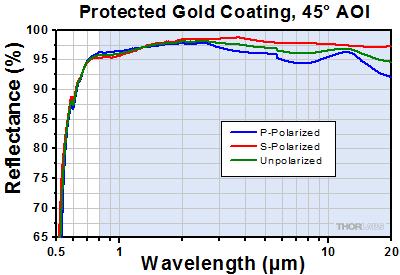
2 O V E R V I E W Features Choose from Seven Coating Options Metallic: UV Enhanced Aluminum, Protected Aluminum, Protected Silver, Protected Gold Dielectric: E02 ( nm), E03 ( nm), or K13 Nd:YAG (532 nm and 1064 nm) Compatible with Our SM1 Lens Tubes and 30 mm Cage System Part Number and Coating are Engraved on the Housing for Easy Identification Post Mountable These Cage Cube Mounted Turning Mirrors provide additional flexibility when building optical devices from our 30 mm cage system and SM1 lens tube products. The mounted turning mirrors are prealigned so that the reflected beam exits to within ±20 arcmin of 90º, which can reduce the time needed for aligning the mirror in a setup. For higher accuracy or more alignment flexibility, see our 90º turning mirror kinematic mounts. The turning mirrors are available with any of seven reflective coatings: UV enhanced aluminum, protected aluminum, CM1 M01 with SM1 Lens Tubes protected silver, protected gold, E02 broadband dielectric ( nm), E03 broadband Mounted to the Entrance and Exit Ports dielectric ( nm), or K13 Nd:YAG dielectric (532 nm and 1064 nm). A complete list of mirror specifications is provided on the Specs tab. Reflectance plots and data are provided on the Graphs tab. Two Mirrors Can be Connected Using ERSCA adapters and 30 mm Cage Rods A bottom located M6 x 0.5 or M4 x 0.7 tap is included for post mounting. Cubes with M6 x 0.5 taps come with 8 32 and M4 adapters for imperial and metric post compatibility (the M6 x 0.5 tap is only compatible with the included adapters). The entrance and exit ports feature our SM1 (1.035" 40) threading for compatibility with Thorlabs' SM1 lens tubes (as seen in the photo to the right) and four 4 40 taps that accept our Ø6 mm cage rods. The mounted turning mirrors can be connected to other cage cubes through the use of our cage rods and ERSCA adapters, as shown to the far right. Please note that two turning mirrors cannot be connected using the CM1 CC Cage Cube Connector (available below) due to a lack of Ø6 mm cage rod holes on two sides of the cube. However, the CM1 CC can be used to attach the turning mirrors to other CM1 style cubes. Each mirror is epoxied within the cage cube and cannot be removed. However, empty 30 mm cage cubes are available below that are compatible with our line of unmounted Prism Mirrors. For a complete selection of our cube mounted optics please see the Mounted Optics Guide tab. Item # CM1 F01 and CCM1 F01/M CM1 G01 and CCM1 G01/M CM1 P01 and CCM1 P01/M CM1 M01 and CCM1 M01/M CM1 E02 and CCM1 E02/M CM1 E03 and CCM1 E03/M CM1 K13 and CCM1 K13/M Unmounted Prism Item # MRA25 F01 MRA25 G01 MRA25 P01 MRA25 M01 MRA25 E02 MRA25 E03 MRA25 K13 Reflective Coating UV Enhanced Aluminum Protected Aluminum Protected Silver Protected Gold E02 Dielectric E03 Dielectric Nd:YAG Dielectric Reflectance (Wavelength Range) R avg > 90% ( nm) R avg > 90% (450 nm 2 μm) R avg > 95% (2 20 μm) R avg > 97.5% (450 nm 2 μm) R avg > 96% (2 20 μm) R avg > 96% (800 nm 20 μm) R avg > 99% ( nm) R avg > 99% ( nm) R s and R p : >98% (532 nm) >99% (1064 nm)
3 S P E C S Metallic Coated Mirrors Item # CM1 F01 and CCM1 F01/M CM1 G01 and CCM1 G01/M CM1 P01 and CCM1 P01/M CM1 M01 and CCM1 M01/M Unmounted Prism Item # MRA25 F01 MRA25 G01 MRA25 P01 MRA25 M01 Reflective Coating UV Enhanced Aluminum Protected Aluminum Protected Silver Protected Gold Reflectance (Wavelength Range) R avg > 90% ( nm) R avg > 90% (450 nm 2 μm) R avg > 95% (2 20 μm) R avg > 97.5% (450 nm 2 μm) R avg > 96% (2 20 μm) R avg > 96% (800 nm 20 μm) Damage Threshold with 10 ns pulse, 10 Hz CW Damage Threshold a 0.3 J/cm 2 (355 nm, Ø W/cm (1.064 µm, Ø W/cm (10.6 µm, Ø J/cm 2 (1064 nm, Ø W/cm (1.064 µm, Ø W/cm (10.6 µm, Ø J/cm 2 (1064 nm, Ø J/cm 2 (1064 nm, Ø W/cm (1.064 µm, Ø W/cm (10.6 µm, Ø0.339 Ports 2 Ports, Each with SM1 (1.035" 40) Threading and Four 4 40 Taps for Cage Rods Post Mounting Mirror Substrate M6 x 0.5 Tapped Hole with 8 32 and M4 x 0.7 Adapters (for Item #s Starting with CM1) M4 x 0.7 Tapped Hole (for Item #s Starting with CCM1) N BK7 Material Housing Engraved Black Anodized Aluminum Housing Surface Flatness (@633 nm) Clear Aperture Surface Quality Beam Path Deviation <λ/10 (Over Clear Aperture) >Ø17.5 mm Scratch Dig 90 ± 20 arcmin 1500 W/cm (1.064 µm, Ø W/cm (10.6 µm, Ø0.339 The power density of your beam should be calculated in terms of W/cm. For an explanation of why the linear power density provides the best metric for long pulse and CW sources, please see the Damage Thresholds tab. Dielectric Coated Mirrors Item # CM1 E02 and CCM1 E02/M CM1 E03 and CCM1 E03/M CM1 K13 and CCM1 K13/M Unmounted Prism Item # MRA25 E02 MRA25 E03 MRA25 K13 Reflective Coating E02 Dielectric E03 Dielectric Nd:YAG Dielectric Reflectance (Wavelength Range) R avg > 99% ( nm) R avg > 99% ( nm) R s and R p : >98% (532 nm) >99% (1064 nm) Damage Threshold with 10 ns pulse, 10 Hz 0.25 J/cm 2 (532 nm, Ø J/cm 2 (810 nm, Ø J/cm 2 (1064 nm, Ø0.433 Ports 2 Ports, Each with SM1 (1.035" 40) Threading and Four 4 40 Taps for Cage Rods Post Mounting Mirror Substrate M6 x 0.5 Tapped Hole with 8 32 and M4 x 0.7 Adapters (for Item #s Starting with CM1) M4 x 0.7 Tapped Hole (for Item #s Starting with CCM1) N BK7 Material Housing Engraved Black Anodized Aluminum Housing Surface Flatness (@633 nm) Clear Aperture Surface Quality Beam Path Deviation <λ/10 (Over Clear Aperture) >Ø17.5 mm 10 5 Scratch Dig 90 ± 20 arcmin 8 J/cm 2 (532 nm, Ø J/cm 2 (1064 nm, Ø1.010

 Protected Silver Coating")

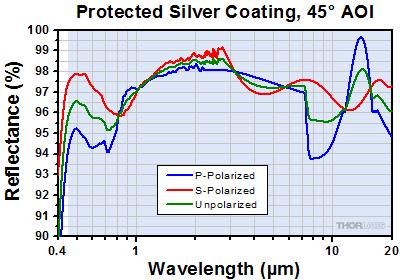
4 Excel Spreadsheet with Raw Data for UV Enhanced Aluminum, 12 and 45 AOI Protected Aluminum Coating (450 nm 20 µm) Excel Spreadsheet with Raw Data for UV Enhanced Aluminum, 12 and 45 AOI Protected Silver Coating (450 nm 20 µm) Excel Spreadsheet with Raw Data for Protected Aluminum, 12 and 45 AOI Excel Spreadsheet with Raw Data for Protected Silver, 12 and 45 AOI


 E03 Coating (750 1100 nm) Excel Spreadsheet with Raw Data for E02 Coating, 8 and 45 AOI Excel Spreadsheet with Raw Data for E03 Coating, 8 and")

5 These plots show the reflectance of our E02 ( nm) and E03 ( nm) dielectric coatings for a typical coating run. The shaded region in each graph denotes the spectral range over which the coating is highly reflective. Due to variations in each run, this recommended spectral range is narrower than the actual range over which the optic will be highly reflective. If you have any concerns about the interpretation of this data, please contact Tech Support. For applications that require a mirror that bridges the spectral range between the dielectric coatings, please consider a metallic mirror. E02 Coating ( nm) E03 Coating ( nm) Excel Spreadsheet with Raw Data for E02 Coating, 8 and 45 AOI Excel Spreadsheet with Raw Data for E03 Coating, 8 and 45 AOI K13 Coating (532 nm and 1064 nm) These plots show the reflectance of our Nd:YAG (532 nm and 1064 nm) dielectric coating for a typical coating run. Although there will be variations in the broadband reflectance from run to run, this optic is guaranteed to meet the reflectance specification at 532 nm and 1064 nm (see the table on the Overview tab). If you have any concerns about the interpretation of this data, please contact Tech Support. Excel Spreadsheet with Raw Data for Dielectric Nd:YAG Laser Line Coating, 8 (Unpolarized) and 45 (S and P Polarized) AOI


6 M O U N T E D O P T I C S G U I D E 30 mm Cage Cube Mounted Optics Selection Guide The table below provides links to all of our 30 mm Cage Cube Mounted optics. For our selection of 16 mm Cage Cube Mounted Optics, please see our 16 mm Cage Systems guide. Non Polarizing Beamsplitter Cube Polarizing Beamsplitter Cube High Power Polarizing Beamsplitter Cube Pellicle Beamsplitters Laser Line Polarizing Beamsplitter Cube Circular / Variable Polarizers Penta Prisms Turning Mirrors Variable Beamsplitters / Attenuators 30 mm Cage Cube Empty Optic Mounts Selection Guide Rectangular Dichroic Mirrors and Filters Empty Compact 30 mm Cage Cube


7 Damage Threshold Data for Thorlabs' Turning Mirrors The specifications to the right are measured data for Thorlabs' turning mirrors. Damage Threshold Specifications Item # Type Damage Threshold CM1 F01 and CCM1 F01/M CM1 G01 and CCM1 G01/M CM1 P01 and CCM1 P01/M CM1 M01 and CCM1 M01/M Pulse CW a Pulse CW a Pulse CW a Pulse CW a 0.3 J/cm 2 (355 nm,10 ns, 10 Hz, Ø W/cm (1.064 µm, Ø W/cm (10.6 µm, Ø J/cm 2 (1064 nm,10 ns, 10 Hz, Ø W/cm (1.064 µm, Ø W/cm (10.6 µm, Ø J/cm 2 (1064 nm,10 ns, 10 Hz, Ø W/cm (1.064 µm, Ø W/cm (10.6 µm, Ø J/cm 2 (1064 nm, 10 ns, 10 Hz, Ø W/cm (1.064 µm, Ø W/cm (10.6 µm, Ø0.339 CM1 E02 and CCM1 E02/M Pulse 0.25 J/cm 2 (532 nm,10 ns, 10 Hz, Ø0.803 CM1 E03 and CCM1 E03/M CM1 K13 and CCM1 K13/M Pulse Pulse 1.0 J/cm 2 (810 nm,10 ns, 10 Hz, Ø J/cm 2 (1064 nm,10 ns, 10 Hz, Ø J/cm 2 (532 nm, 10 ns, 10 Hz, Ø J/cm 2 (1064 nm, 10 ns, 10 Hz, Ø1.010 The power density of your beam should be calculated in terms of W/cm. For an explanation of why the linear power density provides the best metric for long pulse and CW sources, please see the "Continuous Wave and Long Pulse Lasers" section below. Laser Induced Damage Threshold Tutorial The following is a general overview of how laser induced damage thresholds are measured and how the values may be utilized in determining the appropriateness of an optic for a given application. When choosing optics, it is important to understand the Laser Induced Damage Threshold (LIDT) of the optics being used. The LIDT for an optic greatly depends on the type of laser you are using. Continuous wave (CW) lasers typically cause damage from thermal effects (absorption either in the coating or in the substrate). Pulsed lasers, on the other hand, often strip electrons from the lattice structure of an optic before causing thermal damage. Note that the guideline presented here assumes room temperature operation and optics in new condition (i.e., within scratch dig spec, surface free of contamination, etc.). Because dust or other particles on the surface of an optic can cause damage at lower thresholds, we recommend keeping surfaces clean and free of debris. For more information on cleaning optics, please see our Optics Cleaning tutorial. Testing Method Thorlabs' LIDT testing is done in compliance with ISO/DIS11254 specifications. A standard 1 on 1 testing regime is performed to test the damage threshold. First, a low power/energy beam is directed to the optic under test. The optic is exposed in 10 locations to this laser beam for a set duration of time (CW) or number of pulses (pulse repetition frequency specified). After exposure, the optic is examined by a microscope (~100X magnification) for any visible damage. The number of locations that are damaged at a particular power/energy level is recorded. Next, the power/energy is either increased or decreased and the optic is exposed at 10 new locations. This process is repeated until damage is observed. The damage threshold is then assigned to be the highest power/energy that the optic can withstand without causing damage. A histogram such as that below represents the testing of one BB1 E02 mirror. The photograph above is a protected aluminum
8 coated mirror after LIDT testing. In this particular test, it handled 0.43 J/cm 2 (1064 nm, 10 ns pulse, 10 Hz, Ø1.000 before damage. According to the test, the damage threshold of the mirror was 2.00 J/cm 2 (532 nm, 10 ns pulse, 10 Hz, Ø Please keep in mind that these tests are performed on clean optics, as dirt and contamination can significantly lower the damage threshold of a component. While the test results are only representative of one coating run, Thorlabs specifies damage threshold values that account for coating variances. Continuous Wave and Long Pulse Lasers Fluence # of Tested Locations Example Test Data Locations with Damage Locations Without Damage 1.50 J/cm J/cm J/cm J/cm J/cm When an optic is damaged by a continuous wave (CW) laser, it is usually due to the 5.00 J/cm melting of the surface as a result of absorbing the laser's energy or damage to the optical coating (antireflection) [1]. Pulsed lasers with pulse lengths longer than 1 µs can be treated as CW lasers for LIDT discussions. Additionally, when pulse lengths are between 1 ns and 1 µs, LIDT can occur either because of absorption or a dielectric breakdown (must check both CW and pulsed LIDT). Absorption is either due to an intrinsic property of the optic or due to surface irregularities; thus LIDT values are only valid for optics meeting or exceeding the surface quality specifications given by a manufacturer. While many optics can handle high power CW lasers, cemented (e.g., achromatic doublets) or highly absorptive (e.g., ND filters) optics tend to have lower CW damage thresholds. These lower thresholds are due to absorption or scattering in the cement or metal coating. Pulsed lasers with high pulse repetition frequencies (PRF) may behave similarly to CW beams. Unfortunately, this is highly dependent on factors such as absorption and thermal diffusivity, so there is no reliable method for determining when a high PRF laser will damage an optic due to thermal effects. For beams with a large PRF both the average and peak powers must be compared to the equivalent CW power. Additionally, for highly transparent materials, there is little to no drop in the LIDT with increasing PRF. In order to use the specified CW damage threshold of an optic, it is necessary to know the following: 1. Wavelength of your laser 2. Linear power density of your beam (total power divided by 1/e 2 beam diameter) 3. Beam diameter of your beam (1/e 2 ) 4. Approximate intensity profile of your beam (e.g., Gaussian) The power density of your beam should be calculated in terms of W/cm. The graph to the right shows why expressing the LIDT as a linear power density provides the best metric for long pulse and CW sources. In this regime, the LIDT given as a linear power density can be applied to any beam diameter; one does not need to compute an adjusted LIDT to adjust for changes in spot size. This calculation assumes a uniform beam intensity profile. You must now consider hotspots in the beam or other non uniform intensity profiles and roughly calculate a maximum power density. For reference, a Gaussian beam typically has a maximum power density that is twice that of the uniform beam (see lower right). LIDT in linear power density vs. pulse length and spot size. For long pulses to CW, linear power density becomes a constant with spot size. This graph was obtained from [1]. Now compare the maximum power density to that which is specified as the LIDT for the optic. If the optic was tested at a wavelength other than your operating wavelength, the damage threshold must be scaled appropriately. A good rule of thumb is that the damage threshold has a linear relationship with wavelength such that as you move to shorter wavelengths, the damage threshold decreases (i.e., a LIDT of 10 W/cm at 1310 nm scales to 5 W/cm at 655 nm): While this rule of thumb provides a general trend, it is not a quantitative analysis of LIDT vs wavelength. In CW applications, for instance, damage scales more strongly with absorption in the coating and substrate, which does not necessarily scale well with wavelength. While the above procedure provides a good rule of thumb for LIDT values, please contact Tech Support if your wavelength is different from the specified LIDT wavelength. If your power density is less than the adjusted LIDT of the optic, then the optic should work for your application. Please note that we have a buffer built in between the specified damage thresholds online and the tests which we have done, which accommodates variation between batches. Upon request, we can provide individual test information and a testing certificate. The damage analysis will be carried out on a similar optic (customer's optic will not be damaged). Testing may result in additional costs or lead times. Contact Tech Support for more information. Pulsed Lasers
9 As previously stated, pulsed lasers typically induce a different type of damage to the optic than CW lasers. Pulsed lasers often do not heat the optic enough to damage it; instead, pulsed lasers produce strong electric fields capable of inducing dielectric breakdown in the material. Unfortunately, it can be very difficult to compare the LIDT specification of an optic to your laser. There are multiple regimes in which a pulsed laser can damage an optic and this is based on the laser's pulse length. The highlighted columns in the table below outline the relevant pulse lengths for our specified LIDT values. Pulses shorter than 10 9 s cannot be compared to our specified LIDT values with much reliability. In this ultra short pulse regime various mechanics, such as multiphoton avalanche ionization, take over as the predominate damage mechanism [2]. In contrast, pulses between 10 7 s and 10 4 s may cause damage to an optic either because of dielectric breakdown or thermal effects. This means that both CW and pulsed damage thresholds must be compared to the laser beam to determine whether the optic is suitable for your application. Pulse Duration t < 10 9 s 10 9 < t < 10 7 s 10 7 < t < 10 4 s t > 10 4 s Damage Mechanism Avalanche Ionization Dielectric Breakdown Dielectric Breakdown or Thermal Thermal Relevant Damage Specification N/A Pulsed Pulsed and CW CW When comparing an LIDT specified for a pulsed laser to your laser, it is essential to know the following: 1. Wavelength of your laser 2. Energy density of your beam (total energy divided by 1/e 2 area) 3. Pulse length of your laser 4. Pulse repetition frequency (prf) of your laser 5. Beam diameter of your laser (1/e 2 ) 6. Approximate intensity profile of your beam (e.g., Gaussian) The energy density of your beam should be calculated in terms of J/cm 2. The graph to the right shows why expressing the LIDT as an energy density provides the best metric for short pulse sources. In this regime, the LIDT given as an energy density can be applied to any beam diameter; one does not need to compute an adjusted LIDT to adjust for changes in spot size. This calculation assumes a uniform beam intensity profile. You must now adjust this energy density to account for hotspots or other nonuniform intensity profiles and roughly calculate a maximum energy density. For reference a Gaussian beam typically has a maximum energy density that is twice that of the 1/e 2 beam. LIDT in energy density vs. pulse length and spot size. For short pulses, energy density becomes a constant with spot size. This graph was obtained from [1]. Now compare the maximum energy density to that which is specified as the LIDT for the optic. If the optic was tested at a wavelength other than your operating wavelength, the damage threshold must be scaled appropriately [3]. A good rule of thumb is that the damage threshold has an inverse square root relationship with wavelength such that as you move to shorter wavelengths, the damage threshold decreases (i.e., a LIDT of 1 J/cm 2 at 1064 nm scales to 0.7 J/cm 2 at 532 nm): You now have a wavelength adjusted energy density, which you will use in the following step. Beam diameter is also important to know when comparing damage thresholds. While the LIDT, when expressed in units of J/cm², scales independently of spot size; large beam sizes are more likely to illuminate a larger number of defects which can lead to greater variances in the LIDT [4]. For data presented here, a <1 mm beam size was used to measure the LIDT. For beams sizes greater than 5 mm, the LIDT (J/cm2) will not scale independently of beam diameter due to the larger size beam exposing more defects. The pulse length must now be compensated for. The longer the pulse duration, the more energy the optic can handle. For pulse widths between ns, an approximation is as follows: Use this formula to calculate the Adjusted LIDT for an optic based on your pulse length. If your maximum energy density is less than this adjusted LIDT maximum energy density, then the optic should be suitable for your application. Keep in mind that this calculation is only used for pulses between 10 9 s and 10 7 s. For pulses between 10 7 s and 10 4 s, the CW LIDT must also be checked before deeming the optic appropriate for your application.
10 Please note that we have a buffer built in between the specified damage thresholds online and the tests which we have done, which accommodates variation between batches. Upon request, we can provide individual test information and a testing certificate. Contact Tech Support for more information. [1] R. M. Wood, Optics and Laser Tech. 29, 517 (1997). [2] Roger M. Wood, Laser Induced Damage of Optical Materials (Institute of Physics Publishing, Philadelphia, PA, 2003). [3] C. W. Carr et al., Phys. Rev. Lett. 91, (2003). [4] N. Bloembergen, Appl. Opt. 12, 661 (1973).
11 In order to illustrate the process of determining whether a given laser system will damage an optic, a number of example calculations of laser induced damage threshold are given below. For assistance with performing similar calculations, we provide a spreadsheet calculator that can be downloaded by clicking the button to the right. To use the calculator, enter the specified LIDT value of the optic under consideration and the relevant parameters of your laser system in the green boxes. The spreadsheet will then calculate a linear power density for CW and pulsed systems, as well as an energy density value for pulsed systems. These values are used to calculate adjusted, scaled LIDT values for the optics based on accepted scaling laws. This calculator assumes a Gaussian beam profile, so a correction factor must be introduced for other beam shapes (uniform, etc.). The LIDT scaling laws are determined from empirical relationships; their accuracy is not guaranteed. Remember that absorption by optics or coatings can significantly reduce LIDT in some spectral regions. These LIDT values are not valid for ultrashort pulses less than one nanosecond in duration. CW Laser Example Suppose that a CW laser system at 1319 nm produces a 0.5 W Gaussian beam that has a 1/e 2 diameter of 10 mm. A naive calculation of the average linear power density of this beam would yield a value of 0.5 W/cm, given by the total power divided by the beam diameter: However, the maximum power density of a Gaussian beam is about twice the maximum power density of a uniform beam, as shown in the graph to the right. Therefore, a more accurate determination of the maximum linear power density of the system is 1 W/cm. A Gaussian beam profile has about twice the maximum intensity of a uniform beam profile. An AC C achromatic doublet lens has a specified CW LIDT of 350 W/cm, as tested at 1550 nm. CW damage threshold values typically scale directly with the wavelength of the laser source, so this yields an adjusted LIDT value: The adjusted LIDT value of 350 W/cm x (1319 nm / 1550 nm) = 298 W/cm is significantly higher than the calculated maximum linear power density of the laser system, so it would be safe to use this doublet lens for this application. Pulsed Nanosecond Laser Example: Scaling for Different Pulse Durations Suppose that a pulsed Nd:YAG laser system is frequency tripled to produce a 10 Hz output, consisting of 2 ns output pulses at 355 nm, each with 1 J of energy, in a Gaussian beam with a 1.9 cm beam diameter (1/e 2 ). The average energy density of each pulse is found by dividing the pulse energy by the beam area: As described above, the maximum energy density of a Gaussian beam is about twice the average energy density. So, the maximum energy density of this beam is ~0.7 J/cm 2. The energy density of the beam can be compared to the LIDT values of 1 J/cm 2 and 3.5 J/cm 2 for a BB1 E01 broadband dielectric mirror and an NB1 K08 Nd:YAG laser line mirror, respectively. Both of these LIDT values, while measured at 355 nm, were determined with a 10 ns pulsed laser at 10 Hz. Therefore, an adjustment must be applied for the shorter pulse duration of the system under consideration. As described on the previous tab, LIDT values in the nanosecond pulse regime scale with the square root of the laser pulse duration: This adjustment factor results in LIDT values of 0.45 J/cm 2 for the BB1 E01 broadband mirror and 1.6 J/cm 2 for the Nd:YAG laser line mirror, which are to be compared with the 0.7 J/cm 2 maximum energy density of the beam. While the broadband mirror would likely be damaged by the laser, the more specialized laser line mirror is appropriate for use with this system. Pulsed Nanosecond Laser Example: Scaling for Different Wavelengths Suppose that a pulsed laser system emits 10 ns pulses at 2.5 Hz, each with 100 mj of energy at 1064 nm in a 16 mm diameter beam (1/e 2 ) that must be


 at 980 nm, then the resulting output has a linear power density of 5.9 W/cm and an energy density of 1.2 x 10 4 J/cm 2 per pulse.")


12 attenuated with a neutral density filter. For a Gaussian output, these specifications result in a maximum energy density of 0.1 J/cm 2. The damage threshold of an NDUV10A Ø25 mm, OD 1.0, reflective neutral density filter is 0.05 J/cm 2 for 10 ns pulses at 355 nm, while the damage threshold of the similar NE10A absorptive filter is 10 J/cm 2 for 10 ns pulses at 532 nm. As described on the previous tab, the LIDT value of an optic scales with the square root of the wavelength in the nanosecond pulse regime: This scaling gives adjusted LIDT values of 0.08 J/cm 2 for the reflective filter and 14 J/cm 2 for the absorptive filter. In this case, the absorptive filter is the best choice in order to avoid optical damage. Pulsed Microsecond Laser Example Consider a laser system that produces 1 µs pulses, each containing 150 µj of energy at a repetition rate of 50 khz, resulting in a relatively high duty cycle of 5%. This system falls somewhere between the regimes of CW and pulsed laser induced damage, and could potentially damage an optic by mechanisms associated with either regime. As a result, both CW and pulsed LIDT values must be compared to the properties of the laser system to ensure safe operation. If this relatively long pulse laser emits a Gaussian 12.7 mm diameter beam (1/e 2 ) at 980 nm, then the resulting output has a linear power density of 5.9 W/cm and an energy density of 1.2 x 10 4 J/cm 2 per pulse. This can be compared to the LIDT values for a WPQ10E 980 polymer zero order quarter wave plate, which are 5 W/cm for CW radiation at 810 nm and 5 J/cm 2 for a 10 ns pulse at 810 nm. As before, the CW LIDT of the optic scales linearly with the laser wavelength, resulting in an adjusted CW value of 6 W/cm at 980 nm. On the other hand, the pulsed LIDT scales with the square root of the laser wavelength and the square root of the pulse duration, resulting in an adjusted value of 55 J/cm 2 for a 1 µs pulse at 980 nm. The pulsed LIDT of the optic is significantly greater than the energy density of the laser pulse, so individual pulses will not damage the wave plate. However, the large average linear power density of the laser system may cause thermal damage to the optic, much like a high power CW beam. N D : Y A G O P T I C S Thorlabs offers a wide selection of optics optimized for use with Nd:YAG lasers. Please see below for more information. Nd:YAG Optics Selection Dielectric Mirrors Beamsplitters Laser Line Mirrors, 1064 nm, 532 nm, 355 nm, 266 nm Right Angle Prism Mirrors, 1064 nm, 532 nm Cage Cube Mounted Prism Mirrors, 1064 nm, 532 nm Harmonic Beamsplitters, 1064 nm, 532 nm, 355 nm, 266 nm Lenses Objectives Filters High Power Polarizing Beamsplitter Cubes, 1064 nm, 532 nm: Unmounted or Mounted UVFS Plano Convex Lenses, 1064 nm, 532 nm: Unmounted or Mounted Air Spaced Doublets, 1064 nm, 532 nm High Power Focusing Objectives, 1064 nm, 532 nm Laser Line Filters, 1064 nm: Standard or Premium Laser Line Filters, 532 nm: Standard or Premium

13 30 mm Cage Cube Mounted Turning Prism Mirrors Part Number Description Price Availability CCM1 F01/M Customer Inspired!30 mm Cage Cube Mounted UV Enhanced Aluminum Turning Mirror, M4 Tap $ Today CCM1 G01/M Customer Inspired!30 mm Cage Cube Mounted Protected Aluminum Turning Mirror, M4 Tap $ Today CCM1 P01/M Customer Inspired!30 mm Cage Cube Mounted Protected Silver Turning Mirror, M4 Tap $ Today CCM1 M01/M Customer Inspired!30 mm Cage Cube Mounted Protected Gold Turning Mirror, M4 Tap $ Today CCM1 E02/M Customer Inspired!30 mm Cage Cube Mounted E02 Dielectric Turning Mirror, nm, M4 Tap $ Today CCM1 E03/M Customer Inspired!30 mm Cage Cube Mounted E03 Dielectric Turning Mirror, nm, M4 Tap $ Today CCM1 K13/M Customer Inspired!30 mm Cage Cube Mounted Nd:YAG Turning Mirror, 532 and 1064 nm, M4 Tap $ Today CM1 F01 30 mm Cage Cube Mounted UV Enhanced Aluminum Turning Mirror $ Today CM1 G01 30 mm Cage Cube Mounted Protected Aluminum Turning Mirror $ Today CM1 P01 30 mm Cage Cube Mounted Protected Silver Turning Mirror $ Today CM1 M01 30 mm Cage Cube Mounted Protected Gold Turning Mirror $ Today CM1 E02 30 mm Cage Cube Mounted E02 Dielectric Turning Mirror, nm $ Today CM1 E03 30 mm Cage Cube Mounted E03 Dielectric Turning Mirror, nm $ Today CM1 K13 30 mm Cage Cube Mounted Nd:YAG Turning Mirror, 532 and 1064 nm $ Today Cage Cube Connector Connect Two 1.5" Wide Cage Cubes Side by Side Compatible with CM1 and CCM1 Series Cage Cubes The CM1 CC cube connector allows two or more cubes to be connected as shown in the image to the right. Many of our cage cubes are compatible with this connector, including empty cubes, empty dichroic cubes, mounted beamsplitters, mounted penta prisms, and mounted turning mirrors. Two cage cube mounted turning mirrors cannot be connected using the CM1 CC due to a lack of Ø6 mm cage rod holes on two sides of the cube. Alignment Pins Please note that because dowel alignment pins are used, the connector requires drilled holes on the cube face between the SM1 Two CM1 CC Connectors used to Connect Multiple 1.5" Wide Cage Cubes threaded (1.035" 40) ports. If you have an older cube and would like it updated to have alignment holes for free, please contact Technical Support. Alternatively, the alignment pins are press fit inside their mounting holes, and can be pressed out for use with cubes that do not have these alignment holes. Part Number Description Price Availability CM1 CC Cage Cube Connector for Compact 30 mm Cage Cubes $44.10 Today
 Tap 3 Prism Alignment Stops Provide Accuracy of ±20 arcmin CCM1 4ER with Penta Prism")
, 10 mm (0.39\"), 12.7 mm (0.50\"), or 20 mm (0.79\") beamsplitter cube. The base of the cube has an 8 32 (M4) tap to attach to Ø1/2\" Posts. Shown to the far right is a 12.7 mm (0.50\") beamsplitter cube being mounted in the CCM1 4ER using the BS127CAM Beamsplitter Cube Adapter.")
14 Compact 30 mm Cage Cube for Prisms and Beamsplitter Cubes Compatible with 30 mm Cage System and SM1 Lens Tubes Directly Accepts 1" Cubes and 25 mm Right Angle Prisms Mounting Adapters Available for Thorlabs' Beamsplitter Cubes Smaller than 25 mm Four SM1 Threaded Ports Base is Post Mountable via 8 32 (M4) Tap 3 Prism Alignment Stops Provide Accuracy of ±20 arcmin CCM1 4ER with Penta Prism (Optic Sold Separately) These 1.5" wide cage cubes directly accept a 1" or 25 mm square optic, such as a beamsplitter cube or right angle prism, with adapters available here for mounting a 5 mm (0.20"), 10 mm (0.39"), 12.7 mm (0.50"), or 20 mm (0.79") beamsplitter cube. The base of the cube has an 8 32 (M4) tap to attach to Ø1/2" Posts. Shown to the far right is a 12.7 mm (0.50") beamsplitter cube being mounted in the CCM1 4ER using the BS127CAM Beamsplitter Cube Adapter. Two cage cubes can be connected using ER rods and ERSCA Cage Rod Adapters. BS127CAM Beamsplitter Cube Adapter Mounted in the CCM1 4ER Cage Cube (Optic and Adapter Sold Separately) The optic is clamped within the cube by tightening three 1.5 mm hex screws of a tension plate (see image to the right), allowing the user to replace the optic with any other compatible optic when necessary. The optic must sit flush against the three corners of the cube base. Do not overtighten the tension plate, this could damage the optic. The image to the right shows a penta prism mounted in a CCM1 4ER with the outer housing removed. Part Number Description Price Availability CCM1 4ER/M Customer Inspired!Compact Clamping 4 Port Prism/Mirror 30 mm Cage Cube, M4 Tap $ Today CCM1 4ER NEW! Customer Inspired!Compact Clamping 4 Port Prism/Mirror 30 mm Cage Cube, 8 32 Tap $ Today
KNIFE-EDGE RIGHT-ANGLE PRISM MIRRORS
 KNIFE-EDGE RIGHT-ANGLE PRISM MIRRORS Precision Cut Prisms Feature Bevel-Free 90 Angle Dielectric, Silver, Gold, and Aluminum Coatings Available 25 mm x 25 mm Faces Application Idea MRAK25-M01 Mounted on
PHW Position Pinhole Wheel
 P R E C I S I O N P I N H O L E S A N D P I N H O L E W H E E L Standard and High-Power Precision Pinholes Mounted in Ø1" Disks Single Pinhole Sizes from Ø1 μm to Ø1 mm 16-Position Pinhole Wheel with Hole
Laser Induced Damage Threshold of Optical Coatings
 White Paper Laser Induced Damage Threshold of Optical Coatings An IDEX Optics & Photonics White Paper Ronian Siew, PhD Craig Hanson Turan Erdogan, PhD INTRODUCTION Optical components are used in many applications
End Capped High Power Assemblies
 Fiberguide s end capped fiber optic assemblies allow the user to achieve higher coupled power into a fiber core by reducing the power density at the air/ silica interface, commonly the point of laser damage.
Bandpass Edge Dichroic Notch & More
 Edmund Optics BROCHURE Filters COPYRIGHT 217 EDMUND OPTICS, INC. ALL RIGHTS RESERVED 1/17 Bandpass Edge Dichroic Notch & More Contact us for a Stock or Custom Quote Today! USA: +1-856-547-3488 EUROPE:
SELECTION GUIDE MULTIPLE-ORDER QUARTZ WAVEPLATES ZERO-ORDER QUARTZ WAVEPLATES DUAL-WAVELENGTH WAVEPLATES... 85
 WAVEPLATES Mirrors Waveplates are used in applications where the control, synthesis, or analysis of the polarization state of an incident beam of light is required. Our waveplates are constructed of very
FCQ1064-APC 1064 nm 1x4 Narrowband Coupler. Mounted on
 1 X 4 SINGLE MODE FIBER OPTIC COUPLERS Wavelengths from 560 nm to 1550 nm Available 25:25:25:25 Split Ratio Terminated with 2.0 mm Narrow Key or Connectors Use for Splitting Signals FCQ1064-APC 1064 nm
High power VCSEL array pumped Q-switched Nd:YAG lasers
 High power array pumped Q-switched Nd:YAG lasers Yihan Xiong, Robert Van Leeuwen, Laurence S. Watkins, Jean-Francois Seurin, Guoyang Xu, Alexander Miglo, Qing Wang, and Chuni Ghosh Princeton Optronics,
Gentec Electro-Optics, Inc
 Gentec Electro-Optics, Inc. 2013. Accessories for Beam Diagnostics Revision 1.2 2 WARRANTY The Gentec-EO accessories for beam diagnostics carry a one-year warranty (from date of shipment) against material
Gentec Electro-Optics, Inc
 Gentec Electro-Optics, Inc. 2013. Accessories for Beam Diagnostics Revision 2.0 2 WARRANTY The Gentec-EO accessories for beam diagnostics carry a one-year warranty (from date of shipment) against material
Optical Isolator Tutorial (Page 1 of 2) νlh, where ν, L, and H are as defined below. ν: the Verdet Constant, a property of the
 νlh, where ν, L, and H are as defined below. ν: the Verdet Constant, a property of the") Aspheric Optical Isolator Tutorial (Page 1 of 2) Function An optical isolator is a passive magneto-optic device that only allows light to travel in one direction. Isolators are used to protect a source
Aspheric Optical Isolator Tutorial (Page 1 of 2) Function An optical isolator is a passive magneto-optic device that only allows light to travel in one direction. Isolators are used to protect a source
Thermal Heads for Power and Single-Shot Energy - mw to KW, mj to 300J
 Thermal Heads for Power and Single-Shot Energy - mw to KW, mj to 300J The highest damage threshold in the industry Models for 1500W, 5000W and 10KW for high power laser measurement LP coating that can
TECHNICAL QUICK REFERENCE GUIDE MANUFACTURING CAPABILITIES GLASS PROPERTIES COATING CURVES REFERENCE MATERIALS
 TECHNICAL QUICK REFERENCE GUIDE COATING CURVES GLASS PROPERTIES MANUFACTURING CAPABILITIES REFERENCE MATERIALS TABLE OF CONTENTS Why Edmund Optics?... 3 Anti-Reflective (AR) Coatings... 4-16 Metallic Mirror
MicroSpot FOCUSING OBJECTIVES
 OFR P R E C I S I O N O P T I C A L P R O D U C T S MicroSpot FOCUSING OBJECTIVES APPLICATIONS Micromachining Microlithography Laser scribing Photoablation MAJOR FEATURES For UV excimer & high-power YAG
The LINOS Singlets. Our quality criteria:
 The LINOS From convergent lenses and diffuse lenses to best form lenses and aspheres, our extensive selection of simple lenses, or singlets, with various focal lengths and diameters guarantees that you
Photonics West Contact us for a Stock or Custom Quote Today! Edmund Optics BROCHURE
 Edmund Optics BROHURE Photonics West 2017 Product Highlights Beam Expanders Off-xis Parabolic Mirrors Right ngle Prisms ontact us for a Stock or ustom Quote Today! US: +1-856-547-3488 EUROPE: +44 (0) 1904
EE119 Introduction to Optical Engineering Spring 2003 Final Exam. Name:
 EE119 Introduction to Optical Engineering Spring 2003 Final Exam Name: SID: CLOSED BOOK. THREE 8 1/2 X 11 SHEETS OF NOTES, AND SCIENTIFIC POCKET CALCULATOR PERMITTED. TIME ALLOTTED: 180 MINUTES Fundamental
StockOptics. CATALOG 2018 Europe
 StockOptics CATALOG 2018 Europe Dear asphericon customer Within the StockOptics product line, you can choose from an extensive portfolio of precision-polished aspheric lenses, cylinders and axicons. Benefit
why TECHSPEC? From Design to Prototype to Volume Production
 high volume stock optics Lenses From Design to Prototype to Volume Production Prisms Filters why TECHSPEC? Volume Discounts from 6 to 100,000 Pieces Certified Edmund Optics Quality Continual Availability
Optical Components. Table of Contents. Mirrors. Windows & Filters
 Optical Components Mirrors Polarizing Optics UV & IR Optics High Reflectivity...1.3 Laser Line...1.3 Broadband...1.3 Partial Reflecting...1.4 Laser Harmonic Separators...1.4 Anti-Reflection...1.5 Laser
CVI LASER OPTICS ANTIREFLECTION COATINGS
 CVI LASER OPTICS ANTIREFLECTION COATINGS BROADBAND MULTILAYER ANTIREFLECTION COATINGS Broadband antireflection coatings provide a very low reflectance over a broad spectral bandwidth. These advanced multilayer
MULTI-ELEMENT LENSES. Don t see exactly what you are looking for? CVI Laser Optics specializes in prototype to volume production manufacturing!
 MULTI-ELEMENT LENSES Mirrors Multi-element lenses are an ideal solution for applications requiring specialized performance and/or a high degree of aberration correction. Our line of multi-element lenses
k λ NA Resolution of optical systems depends on the wavelength visible light λ = 500 nm Extreme ultra-violet and soft x-ray light λ = 1-50 nm
 Resolution of optical systems depends on the wavelength visible light λ = 500 nm Spatial Resolution = k λ NA EUV and SXR microscopy can potentially resolve full-field images with 10-100x smaller features
Title: Laser marking with graded contrast micro crack inside transparent material using UV ns pulse
 Cover Page Title: Laser marking with graded contrast micro crack inside transparent material using UV ns pulse laser Authors: Futoshi MATSUI*(1,2), Masaaki ASHIHARA(1), Mitsuyasu MATSUO (1), Sakae KAWATO(2),
The LINOS Plano Optics
 The LINOS Plano Optics LINOS is known for high-quality plane plates from optical glass, fused silica and sapphire, as well as a variety of prisms, filters, beam splitters, reticles and dispersion plates.
Physics 431 Final Exam Examples (3:00-5:00 pm 12/16/2009) TIME ALLOTTED: 120 MINUTES Name: Signature:
 TIME ALLOTTED: 120 MINUTES Name: Signature:") Physics 431 Final Exam Examples (3:00-5:00 pm 12/16/2009) TIME ALLOTTED: 120 MINUTES Name: PID: Signature: CLOSED BOOK. TWO 8 1/2 X 11 SHEET OF NOTES (double sided is allowed), AND SCIENTIFIC POCKET CALCULATOR
Physics 431 Final Exam Examples (3:00-5:00 pm 12/16/2009) TIME ALLOTTED: 120 MINUTES Name: PID: Signature: CLOSED BOOK. TWO 8 1/2 X 11 SHEET OF NOTES (double sided is allowed), AND SCIENTIFIC POCKET CALCULATOR
Pyroelectric, Photodiode and RP Heads for Repetitive Energy Measurements
 Pyroelectric, Photodiode and RP Heads for Repetitive Energy Measurements Pyroelectric and Photodiode Heads RP Heads For latest updates please visit our website: www.ophiropt.com 1 Pyroelectric and Photodiode
POWER DETECTORS. How they work POWER DETECTORS. Overview
 G E N T E C - E O POWER DETECTORS Well established in this field for over 30 years Gentec Electro-Optics has been a leader in the field of laser power and energy measurement. The average power density
High Volume Stock optics
 High Volume Stock optics From Design to Prototype to Volume Production TECHSPEC Lenses TECHSPEC prisms TECHSPEC filters COPYRIGHT COPYRIGHT 2011 EDMUND 2014 EDMUND OPTICS, OPTICS, INC. ALL INC. RIGHTS
Laser Speckle Reducer LSR-3000 Series
 Datasheet: LSR-3000 Series Update: 06.08.2012 Copyright 2012 Optotune Laser Speckle Reducer LSR-3000 Series Speckle noise from a laser-based system is reduced by dynamically diffusing the laser beam. A
High Power Laser Delivery Assemblies COPPER FERRULE PVC COVERED SST MONOCOIL. fiberguide ANODIZED ALUMINUM HEATSINK AIRGAP TECHNOLOGY - NO EPOXY
 DESCRIPTION Multimode, step-index fibers offer a simple, efficient way to accurately deliver high power laser beams without the use of bulky, inconvenient and often heavy articulated arms. Much care has
Beam Splitters. Diameter ET Transmission Reflectance %
 Beam Splitters Beam splitters allow a beam to be split into two beams of differing power, however, the most popular power split is 50:50 at a 45 incidence angle. The polarization needs to be considered
ND:YAG/ND:YLF...T-26 TUNABLE LASER MIRRORS...T-28 MISCELLANEOUS MIRRORS...T-30 ANTI-REFLECTIVE OVERVIEW...T-31 0 DEGREE ANGLE OF INCIDENCE...
 COATING TRACES HIGH REFLECTION COATING TRACES Coating Backgrounder ND:YAG/ND:YLF...T-26 TUNABLE LASER MIRRORS...T-28 MISCELLANEOUS MIRRORS...T-30 ANTI-REFLECTION COATING TRACES ANTI-REFLECTIVE OVERVIEW...T-31
High Power Laser Delivery Assemblies COPPER FERRULE PVC COVERED SST MONOCOIL. fiberguide AIRGAP TECHNOLOGY - NO EPOXY
 DESCRIPTION Multimode, step-index fibers offer a simple, efficient way to accurately deliver high power laser beams without the use of bulky, inconvenient and often heavy articulated arms. Much care has
Nmark AGV-HP. High Accuracy, Thermally Stable Galvo Scanner
 Nmark AGV-HP Galvanometer Nmark AGV-HP High Accuracy, Thermally Stable Galvo Scanner Highest accuracy scanner available attains single-digit, micron-level accuracy over the field of view Optical feedback
The RSH Catalogue. Laser Optics & Lenses
 The RSH Catalogue Laser Optics & Lenses 2013 2014 1 Company Profile RSH Optronics, Headquartered in Ajmer, Rajasthan, India, is the leading supplier & manufacturer for Photonics Products (Optics, Laser
Laser Safety & the Human Eye Recall the human eye is a simple single lens system Crystalline lens provide focus Cornea: outer surface protection
 Laser Safety & the Human Eye Recall the human eye is a simple single lens system Crystalline lens provide focus Cornea: outer surface protection Iris: control light Retina: where image is focused Note
P r i s m s I N D E X
 P r i s m s P r i s m s I N D E X Selection By processing the various forms of glass, the prism produces a special effect due to refraction. Since there is no angular offset that after manufacture, it
Where Image Quality Begins
 Where Image Quality Begins Filters are a Necessity Not an Accessory Inexpensive Insurance Policy for the System The most cost effective way to improve repeatability and stability in any machine vision
101 W of average green beam from diode-side-pumped Nd:YAG/LBO-based system in a relay imaged cavity
 PRAMANA c Indian Academy of Sciences Vol. 75, No. 5 journal of November 2010 physics pp. 935 940 101 W of average green beam from diode-side-pumped Nd:YAG/LBO-based system in a relay imaged cavity S K
Understanding Optical Specifications
 Understanding Optical Specifications Optics can be found virtually everywhere, from fiber optic couplings to machine vision imaging devices to cutting-edge biometric iris identification systems. Despite
How to Avoid Thermal Sensor Damage & Out of Tolerance Conditions
 About Ophir-Spiricon With over 30 years of experience, the Ophir Photonics Group provides a complete line of instrumentation including power and energy meters, beam profilers, spectrum analyzers, and goniometric
Optical Systems. Selection Guide. Simple Telescope Kit page 6.4. Variable Attenuators for linearly polarized laser beam page 6.
 Selection Guide F-Theta Lens page 6. Compact Beam Expander page 6.3 Zoom Beam Expander page 6.3 Simple Telescope Kit page 6.4 Gauss-to-Top Hat Beam Shaping Lens page 6.5 Continuously Variable Attenuator
Practical Applications of Laser Technology for Semiconductor Electronics
 Practical Applications of Laser Technology for Semiconductor Electronics MOPA Single Pass Nanosecond Laser Applications for Semiconductor / Solar / MEMS & General Manufacturing Mark Brodsky US Application
Laser Diode Bar Assemblies
 Product Division Laser Diode Bar Assemblies Product PH-800-QCW Description 800W QCW pumping power, Ø3mm rod Main Features This compact laser pumping head consists of six water-cooled diode laser bars arranged
Examination Optoelectronic Communication Technology. April 11, Name: Student ID number: OCT1 1: OCT 2: OCT 3: OCT 4: Total: Grade:
 Examination Optoelectronic Communication Technology April, 26 Name: Student ID number: OCT : OCT 2: OCT 3: OCT 4: Total: Grade: Declaration of Consent I hereby agree to have my exam results published on
Pockels Cells. Selection Guide. BBO Pockels Cells page 3.4. DQ High Repetition Rate Pockels Cell Driver for Q-Switching page 3.6
 Selection Guide Drivers & High Voltage Supplies KTP page 3.2 Mounting Stage for of Ø25.4 mm page 3.5 DPB High Voltage Pockels Cell Driver page 3.12 KD*P page 3.3 Pulse Picking Solutions page 3.15 Mounting
Components. Table of Contents. FemtoLine Laser Crystals. FemtoLine Laser Optics. Cleaning Instructions
 Components Table of Contents Laser Mirrors...5. Low GDD Ultrafast Mirrors...5. Dual Band Mirrors...5. Broadband Low GDD Ultrafast Mirrors...5.5 Laser Harmonic Separators...5.6 Laser Output Couplers...5.7
COLLIMATORS AND FOCUSERS RECEPTACLE STYLE
 COLLIMATORS AND FOCUSERS RECEPTACLE STYLE FEATURES: High power handling Rugged and compact design Low insertion loss Wide wavelength range 200-2100 nm Wide range of beam diameters GRIN, aspheric, achromatic,
IntroOptical Filters. Windows
 IntroOptical Filters Filter Specifications............ 286 Filter Selection Guide........... 288 Custom and Image Filters........ 291 Interference Filters............. 292 High Rejection Laser Line Filters...
Nmark AGV-HP. High Accuracy, Thermally Stable Galvo Scanner
 Nmark AGV-HP High Accuracy, Thermally Stable Galvo Scanner Highest accuracy scanner available attains single-digit, micron-level accuracy over the field of view Optical feedback technology significantly
directly on each side of the crystal to form a rugged, monolithic oscillator that is end pumped by a CW diode laser.
 Product Bulletin MicroChip NanoPulse, NanoGreen, and NanoEyeSafe CDRH Solid-State Lasers The JDS Uniphase MicroChip NanoLaser produces high peak power, high repetition rates, and short pulses from compact,
DISPERSION COMPENSATING FIBER
 DISPERSION COMPENSATING FIBER Dispersion-Compensating SM Fiber for Telecom Wavelengths (1520-1625 nm) DCF38 is Specifically Designed to Compensate Corning SMF-28e+ Fiber Short Pulse Broad Pulse due to
Machine Vision Lyte-MV 2
 Machine Vision Lyte-MV 2 The Lyte-MV 2 Range The Lyte-MV 2 provides a reliable industrial light source for a wide range of machine vision applications including triangulation, 3D inspection and alignment.
Atlantic. Industrial High Power Picosecond Lasers. features
 Atlantic Industrial High Power Picosecond Lasers lasers have been designed as a versatile tool for a variety of industrial material processing applications. They are compact, OEM rugged, with up to 8 W
Precision Micro-Aperture Catalog
 National Aperture, Inc. Precision Micro-Aperture Catalog Version 2012 PLEASE CONTACT: Data Optics, Inc. Distributor for National Aperture, Inc. Phone: (734) 483-8228 (800) 321-9026 Fax: (734) 483-9879
Comparison of FRD (Focal Ratio Degradation) for Optical Fibres with Different Core Sizes By Neil Barrie
 for Optical Fibres with Different Core Sizes By Neil Barrie") Comparison of FRD (Focal Ratio Degradation) for Optical Fibres with Different Core Sizes By Neil Barrie Introduction The purpose of this experimental investigation was to determine whether there is a dependence
Comparison of FRD (Focal Ratio Degradation) for Optical Fibres with Different Core Sizes By Neil Barrie Introduction The purpose of this experimental investigation was to determine whether there is a dependence
ICALEO 2007, October 29 November 1, Hilton in the WALT DISNEY WORLD Resort, Orlando, FL, USA
 WHAT IS THE BEST CHOICE FOR LASER MATERIAL PROCESSING ROD, DISK, SLAB OR FIBER? Paper 201 Erwin Steiger Erwin Steiger LaserService, Graf-Toerring-Strasse 68, Maisach, Bavaria, 82216, Germany Abstract Laser
Laser Speckle Reducer LSR-3000 Series
 Laser Speckle Reducer LSR-3000 Series Speckle noise from a laser-based system is reduced by dynamically diffusing the laser beam. A diffuser is bonded to a thin elastic membrane, which includes four independent
1. INTRODUCTION 2. LASER ABSTRACT
 Compact solid-state laser to generate 5 mj at 532 nm Bhabana Pati*, James Burgess, Michael Rayno and Kenneth Stebbins Q-Peak, Inc., 135 South Road, Bedford, Massachusetts 01730 ABSTRACT A compact and simple
BEAM PROFILING CAMERAS
 PRESENTATION CAMERAS PRESENTATION SPECIAL PRODUCTS OEM DETECTORS THZ DETECTORS PHOTO DETECTORS HIGH POWER SOLUTIONS POWER DETECTORS ENERGY DETECTORS MONITORS MAIN SPECIFICATIONS Wavelength Range BEAM PROFILING
Practical Guide to Specifying Optical Components
 Practical Guide to Specifying Optical Components OPTI 521 Introduction to Opto-Mechanical Engineering Fall 2012 December 10, 2012 Brian Parris Introduction This paper is intended to serve as a practical
High Power and Energy Femtosecond Lasers
 High Power and Energy Femtosecond Lasers PHAROS is a single-unit integrated femtosecond laser system combining millijoule pulse energies and high average powers. PHAROS features a mechanical and optical
WARRANTY. Any unauthorized alteration or repair of the product is also not covered by the warranty.
 First Year Warranty WARRANTY The Gentec-EO thermal power and energy detectors carry a one-year warranty (from date of shipment) against material and /or workmanship defects when used under normal operating
SURFACE ANALYSIS STUDY OF LASER MARKING OF ALUMINUM
 SURFACE ANALYSIS STUDY OF LASER MARKING OF ALUMINUM Julie Maltais 1, Vincent Brochu 1, Clément Frayssinous 2, Réal Vallée 3, Xavier Godmaire 4 and Alex Fraser 5 1. Summer intern 4. President 5. Chief technology
Power Sensors Introduction
 Introduction Introduction and Selection Charts & Coherent uses three primary coatings to capture the incident radiation on our thermal sensors. The specifications for each sensor list which coating is
Micro Precision Apertures
 National Aperture, Inc. Micro Precision Apertures Product Guide Precision apertures, targets and patterns, including round, slit, square, etc., for universal and high power applications National Aperture,
Acculase Green PWM. Direct Drive Green Laser Diode Module
 Acculase Green PWM Direct Drive Green Laser Diode Module Acculase Direct Drive Green Available in 520nm wavelength and with powers output powers up to 35mW the Acculase Direct Drive Green PWM represents
Pockels Cells. Selection Guide. KD*P Pockels Cells page 3.3. DQ High Repetition Rate Pockels Cell Driver for Q-Switching page 3.6
 Selection Guide Drivers & High Voltage Supplies KTP page 3.2 Mounting Stages for of Ø25.4 mm page 3.5 DPB High Voltage Pockels Cell Driver page 3.12 Pulse Picking Solutions page 3.15 Mounting Stages for
The Laser Processing of Diamond and Sapphire
 The Laser Processing of Diamond and Sapphire Neil Sykes Micronanics Limited neil@micronanics.com Diamond Diamond has the highest hardness and thermal conductivity of any bulk material 10/10 on the Mohs
WL Photonics Inc. Leading Provider of Fiber Optic Wavelength Tuning and Conditioning Solutions
 Faraday Optical Isolator FI-PS-, FI-PI- & FI-BP- Faraday optical isolators of FI- series are built with the superior materials of large Verdet constant, high thermal conductivity, low absorption coefficient
NL300 series. Compact Flash-Lamp Pumped Q-switched Nd:YAG Lasers FEATURES APPLICATIONS NANOSECOND LASERS
 NL200 NL210 NL230 NL300 NL740 electro-optically Q-switched nanosecond Nd:YAG lasers produce high energy pulses with 3 6 ns duration. Pulse repetition rate can be selected in range of 5 20 Hz. NL30 HT models
CHAPTER 9 POSITION SENSITIVE PHOTOMULTIPLIER TUBES
 CHAPTER 9 POSITION SENSITIVE PHOTOMULTIPLIER TUBES The current multiplication mechanism offered by dynodes makes photomultiplier tubes ideal for low-light-level measurement. As explained earlier, there
Will contain image distance after raytrace Will contain image height after raytrace
 Name: LASR 51 Final Exam May 29, 2002 Answer all questions. Module numbers are for guidance, some material is from class handouts. Exam ends at 8:20 pm. Ynu Raytracing The first questions refer to the
CONFOCAL MICROSCOPE CM-1
 CONFOCAL MICROSCOPE CM-1 USER INSTRUCTIONS Scientific Instruments Dr. J.R. Sandercock Im Grindel 6 Phone: +41 44 776 33 66 Fax: +41 44 776 33 65 E-Mail: info@jrs-si.ch Internet: www.jrs-si.ch 1. Properties
How-to guide. Working with a pre-assembled THz system
 How-to guide 15/06/2016 1 Table of contents 0. Preparation / Basics...3 1. Input beam adjustment...4 2. Working with free space antennas...5 3. Working with fiber-coupled antennas...6 4. Contact details...8
Multi-Element Overview
 Intro Lenses Overview........ 128 Windows Achromats 425-675nm Cemented Doublets. 132 425-675nm Fast Achromats..... 133 1064/633nm Air-Spaced...... 134 1064/532nm Air-Spaced...... 135 Aplanats Visible....................
Novel laser power sensor improves process control
 Novel laser power sensor improves process control A dramatic technological advancement from Coherent has yielded a completely new type of fast response power detector. The high response speed is particularly
Hamidreza Karbasi, P. Eng., PhD Conestoga College ITAL Oct. 7, 2010
 Presented at the COMSOL Conference 2010 Boston Presented by: Hamidreza Karbasi, P. Eng., PhD Conestoga College ITAL Oct. 7, 2010 Creating and Building Sustainable Environments Outline Background Objectives
PREPARED BY: I. Miller DATE: 2004 May 23 CO-OWNERS REVISED DATE OF ISSUE/CHANGED PAGES
 Page 1 of 30 LIGHTMACHINERY TEST REPORT LQT 30.11-1 TITLE: HMI Michelson Interferometer Test Report Serial Number 1 - Wideband FSR INSTRUCTION OWNER HMI Project Manager PREPARED BY: I. Miller DATE: 2004
How to Properly Select a Laser Power or Energy Sensor
 How to Properly Select a Laser Power or Energy Sensor By Dick Rieley, Sales Manager, Mid Altantic and Southeast Regions, Ophir-Spiricon LLC The selection of a sensor to accurately measure the power of
Laser-Produced Sn-plasma for Highvolume Manufacturing EUV Lithography
 Panel discussion Laser-Produced Sn-plasma for Highvolume Manufacturing EUV Lithography Akira Endo * Extreme Ultraviolet Lithography System Development Association Gigaphoton Inc * 2008 EUVL Workshop 11
ABSTRACT 1. INTRODUCTION
 Control of pulse duration and shape in a 4-W Q-switched 532-nm laser Simon Chard, Timothy S. McComb, Ying Chen, Michael Barty, Young Key Kwon Andritz Powerlase Limited, 3 & 4 Meadowbrook Industrial Centre,
capabilities Infrared Contact us for a Stock or Custom Quote Today!
 Infrared capabilities o 65+ Stock Components Available for Immediate Delivery o Design Expertise in SWIR, Mid-Wave, and Long-Wave Assemblies o Flat, Spherical, and Aspherical Manufacturing Expertise Edmund
Premier & Acculase Range Modular Modulatable Lasers
 Premier & Acculase Range Modular Modulatable Lasers Features Flexible design accommodating wide range of lens and diode options High bore sight accuracy on Acculase model Visible and Infra red versions
Silicon Photomultiplier Evaluation Kit. Quick Start Guide. Eval Kit SiPM. KETEK GmbH. Hofer Str Munich Germany.
 KETEK GmbH Hofer Str. 3 81737 Munich Germany www.ketek.net info@ketek.net phone +49 89 673 467 70 fax +49 89 673 467 77 Silicon Photomultiplier Evaluation Kit Quick Start Guide Eval Kit Table of Contents
1.2 BeamTrack Power / Position / Size Sensors
 1.2 BeamTrack Power / Position / Size Ophir now has the new BeamTrack line of thermal sensors that can measure beam position and beam size while measuring power. This innovative device will provide an
Vision 1. Physical Properties of Light. Overview of Topics. Light, Optics, & The Eye Chaudhuri, Chapter 8
 Vision 1 Light, Optics, & The Eye Chaudhuri, Chapter 8 1 1 Overview of Topics Physical Properties of Light Physical properties of light Interaction of light with objects Anatomy of the eye 2 3 Light A
High power UV from a thin-disk laser system
 High power UV from a thin-disk laser system S. M. Joosten 1, R. Busch 1, S. Marzenell 1, C. Ziolek 1, D. Sutter 2 1 TRUMPF Laser Marking Systems AG, Ausserfeld, CH-7214 Grüsch, Switzerland 2 TRUMPF Laser
Infrared wire grid polarizers: metrology, modeling, and laser damage threshold
 Infrared wire grid polarizers: metrology, modeling, and laser damage threshold Matthew George, Bin Wang, Jonathon Bergquist, Rumyana Petrova, Eric Gardner Moxtek Inc. Calcon 2013 Wire Grid Polarizer (WGP)
Dicing of Thin Silicon Wafers with Ultra-Short Pulsed Lasers in the Range from 200 fs up to 10 ps
 Technical Communication JLMN-Journal of Laser Micro/Nanoengineering Vol. 10, No. 2, 2015 Dicing of Thin Silicon Wafers with Ultra-Short Pulsed Lasers in the Range from 200 fs up to 10 ps C. Fornaroli 1,
FireFly Green. It is a self-contained laser that offers the user increased stability over a wide operating temperature and with a faster warm up time.
 FireFly Green FireFly Green The FireFly Green range sets a new standard for industrial grade, green laser diode modules. A radically new design provides TE stabilised performance without TE cost and power
Design Description Document
 UNIVERSITY OF ROCHESTER Design Description Document Flat Output Backlit Strobe Dare Bodington, Changchen Chen, Nick Cirucci Customer: Engineers: Advisor committee: Sydor Instruments Dare Bodington, Changchen
EDMUND OPTICS ULTRAVIOLET OPTICS
 Edmund Optics BROCHURE EDMUND OPTICS ULTRAVIOLET OPTICS TECHNICAL RESOURCES PRODUCTS CASE STUDY Contact us for a Stock or Custom Quote Today! USA: +1-856-547-3488 EUROPE: +44 (0) 1904 788600 ASIA: +65
ECEN. Spectroscopy. Lab 8. copy. constituents HOMEWORK PR. Figure. 1. Layout of. of the
 ECEN 4606 Lab 8 Spectroscopy SUMMARY: ROBLEM 1: Pedrotti 3 12-10. In this lab, you will design, build and test an optical spectrum analyzer and use it for both absorption and emission spectroscopy. The
EXPRIMENT 3 COUPLING FIBERS TO SEMICONDUCTOR SOURCES
 EXPRIMENT 3 COUPLING FIBERS TO SEMICONDUCTOR SOURCES OBJECTIVES In this lab, firstly you will learn to couple semiconductor sources, i.e., lightemitting diodes (LED's), to optical fibers. The coupling
CORPORATE PRESENTATION
 CORPORATE PRESENTATION WHO WE ARE Edmund Optics is a global OPTICS and IMAGING company that manufactures and supplies the worldwide technical community with precision optical components and subassemblies.
Autotracker III. Applications...
 Autotracker III Harmonic Generation System Model AT-III Applications... Automatic Second Harmonic and Third Harmonic Generation of UV Wavelengths Automatic Production of IR Wavelengths by Difference Frequency
ADVANCED OPTICS LAB -ECEN Basic Skills Lab
 ADVANCED OPTICS LAB -ECEN 5606 Basic Skills Lab Dr. Steve Cundiff and Edward McKenna, 1/15/04 Revised KW 1/15/06, 1/8/10 Revised CC and RZ 01/17/14 The goal of this lab is to provide you with practice
Miniature collimator for POF fiber: large aperture Model 011-TU2
 Example testing Report for: M011-TU2 Miniature collimator for POF fiber: large aperture Model 011-TU2 Testing report Move along this direction to adjust lens Model 011_TU2 with glass lens Part Number: