Geo/SAT 2 MAP MAKING IN THE INFORMATION AGE
|
|
|
- Julian Reed
- 5 years ago
- Views:
Transcription

1 Geo/SAT 2 MAP MAKING IN THE INFORMATION AGE Professor Paul R. Baumann Department of Geography State University of New York College at Oneonta Oneonta, New York USA COPYRIGHT 2008 Paul R. Baumann
2 INTRODUCTION: As the World rapidly enters the Information Age, the need for better and up-to-date maps becomes essential. People are finding it difficult, through the traditional written methods of communication, to absorb all the items with which they must deal during this new age. Basically, they are being overwhelmed with information. To handle partially this situation, more and more information is being presented graphically rather than textually. The map is a graphical communication medium by which a tremendous amount of information can be conveyed quickly. However, in order for the map to be an effective means of communication, it must be understood and it must be up-to-date and accurate. For more than two decades British educator William Balchin has promoted the idea that K-12 school curricula should include geography with English and mathematics as foundation subjects. He notes that the four types of basic intelligence - verbal, social, numerical, and visual-spatial - relate to literacy, articulacy, numeracy, and graphicacy. He defines graphicacy as the communication of spatial information that cannot be conveyed adequately by verbal or numerical means. The tools of graphicacy are maps, diagrams, photographs, and other spatial documents. Many maps are not accurate and are out-of-date, which can create problems for people using them to make decisions. It is a very difficult and time-consuming task to keep maps accurate and current. Like other map agencies throughout the world, the United States Geological Survey (USGS) is constantly striving to address this problem. In one map series alone it has to deal with the more than 54,000 large-scale topographic maps covering the 48 contiguous States and Hawaii. Remotely sensed imagery has become a valuable means for keeping maps accurate and up-to-date. The goal of this instructional is to present a methodology for updating the location and size of certain water bodies within a particular area of a USGS 7.5 minute topographic map. This methodology employs a Landsat TM (Thematic Mapper) data set, which covers a study area of 96.3 square miles or square kilometers. The data set depicts conditions present on May 29, 1994 over the Kossuth, Indiana USGS topographic sheet. The USGS 7.5 Minute Topographic Quadrangle(Map)for Kossuth was originally produced in 1963, photorevised in 1980, and updated with minor revision in BACKGROUND: Kossuth Topographic Map The Kossuth USGS 7.5-minute topographic sheet is situated in the northern portion of Washington County, in southern Indiana. The Kossuth topographic sheet is typical of most of the USGS maps throughout the United States in that it covers a landscape which is not particularly spectacular but nonetheless interesting. The area is very rural with the major community being the hamlet of Kossuth (population 50, 1990). Some of the more appealing place names found on the map sheet, which reflect the southern Indiana milieu, are Potato Knob, Crossroads Church, Pumpkin Center, and Suicide Cave. Figure 1 is a generalized map (scale 1:250,000), which covers the Kossuth topographic sheet and

3 beyond. Click on this map and the Kossuth 7.5-minute topographic sheet will appear. This is a large file, which may take a few monuments to display. FIGURE 1 The most prominent landscape feature on the Kossuth USGS 7.5 minute topographic map is the Delaney Creek valley with the surrounding roughly dissected uplands. The valley floor is relatively flat and ranges from 550 to 600 feet in elevation. Deciduous trees grow along Delaney Creek, and corn and soybean fields cover the lower portions of the valley. Small fields of tobacco exist near the edges of the valley. The creek with its many small tributaries forms a classical dendritic drainage pattern. The uplands sharply rise from the valley floor and reach elevations of 850 to 900 feet. Mainly mixed forests of deciduous and evergreen trees cover them. Most of the area falls within the Jackson-Washington State Forest.


4 FIGURE 2 Figure 2 shows the typical small tobacco field with the uplands immediately behind it. This section of Indiana rests at the northern edge of the Kentucky tobacco region. Many old families in this section of Indiana trace their heritage back to Virginia by way of Kentucky. In such families tobacco has been a cash crop for generations and it has become as much a habit to grow it as to smoke and chew it. FIGURE 3 In Figure 3 a cornfield spreads across the valley bottom. Note the sudden contrast in slope and elevation between the valley bottom and the uplands. Also, note the haze over

5 the hills, which generally indicates the beginning of a late summer, afternoon thunderstorm. This type of haze makes it difficult to obtain sharp satellite imagery over this region in the late summer. In addition, the heavy cover of green crops reduces significantly the contrast between the valley floor and the uplands. The imagery used in the module was taken in late May when the crops in the fields have just started to appear and most of the land cover is still bare ground, which helps to differentiate the valley floor from the uplands. See Figure 6. FIGURE 4 The Kossuth topographic map cuts across three physiographic regions. The Scottsburg Lowland extends along the northern edge of the map. This is a low (500 to 550 feet), flat area on which the Muscatatuck River meanders. Muscatatuck does not appear on the map but can be seen on the data set imagery. The Delaney Creek flows northward into the Muscatatuck, which eventually enters the East Fork of the White River and then the Wabash. The Norman Uplands occupy the major portion of the map area. Along the edge of the Norman Uplands and Scottsburg Lowland is the Knobstone escarpment, which has thin beds of soft fine-grained bluish-gray sandstones and shales. These sandstones and shales erode easily and are responsible for the deep dissections into the Norman Upland, which are clearly evident on the map. The southern portion of the map relates to the Mitchell Plain. This is a limestone plain, which dips quickly away from the Norman Uplands. As one drives south out of the Delaney Creek valley, one is crossing a divide where the Blue River starts its southern journey to the Ohio River. The Mitchell Plain with its limestone formations is a karst region with caves and sinkholes. Some of the small, dot size ponds on the bottom section of the topographic map are sinkholes with water in them. Figure 4 shows the major physiographic regions of southern Indiana with the political boundaries of Washington County superimposed on the three regions just described. It also identifies the location of the southern boundaries of the Illinoian and
 entering the Delaney Creek valley.")
6 Wisconsin glaciers. The continental glaciers never covered a large section of southern Indiana, including most of Washington County. The Kossuth topographic map shows several reservoirs nestled into the tributary valleys (hollows) entering the Delaney Creek valley. The reservoirs are colored purple on the map, which means that they were added to the map at a later date. The information on the reservoirs was obtained from aerial photographs and other sources but the information was not field checked. The reservoirs provide flood control for the Delaney Creek valley. With the steep slopes of the uplands and the frequent heavy summer thunderstorms associated with southern Indiana, small but devastating floods can occur suddenly in the valley area. The large reservoir (Figure 5) in Clay Hill Hollow is also used for recreation and forms the heart of Delaney Creek Park, which is maintained by the county. Note that the reservoirs are situated on the valley floor and are covering good farmland. Water Bodies FIGURE 5 The Kossuth map was originally produced in 1963 and photorevised in As previously indicated, producing an accurate and up-to-date map is a long and complex process. It normally takes five years from the identification of a USGS 7.5 minute mapping project to the printing of the final map. This process requires a team of professionals and a series of closely coordinated steps. It used to take longer to produce a map because much of the needed information was gathered by field work and surveying, which are very expensive procedures. In recent decades the USGS has turned more toward aerial photography to obtain the required information. Most photographs used for the USGS s topographic mapping program are now acquired through the National Aerial Photography Program (NAPP). NAPP flights are flown in a north-south direction along carefully determined flight lines. It takes 10 precisely positioned NAPP aerial photographs to provide the stereoscope coverage needed for each 7.5 minute map. At this
7 coverage level NAPP photographs are mainly at the scale of 1:40,000. They are also generally black-and-white photographs. At this scale and with only black-and-white photographs an aerial photo interpreter might overlook some features. An examination of the satellite data set (Figure 6) being used in this module shows the location of several more reservoirs in the Delaney Creek valley, which do not appear on the 1980 photorevised map. These reservoirs could have been built after 1980, and thus, would not appear on the NAPP photographs. However, the map states that minor revisions were made in 1994, the year that the satellite data set was acquired. The minor revisions were noted on the map in the following manner: Photoinspected from 1992 source; no major culture or drainage changes observed. Boundaries revised and names verified The missing reservoirs probably were not constructed within the two year period between 1992, the date of the photo source, and 1994, the date of the satellite imagery. It would take several years to build and fill such reservoirs. It would also take time for vegetation to cover the earth dams and other disturbed lands around the reservoirs. Disturbed land surfaces would produce bright reflectances on the imagery. No such reflectances occur around these reservoirs indicating no recent construction. In addition, the minor revisions were dated Funds for building these reservoirs came from the Soil Conservation Service of the U.S. Department of Agriculture; thus, their existence had to be known. The problem most likely rests with the pressure and demand to provide up-to-date information, in this case map information, without giving full consideration to accuracy. The objective of this instructional module is to locate and measure these missing reservoirs using satellite imagery. Figure 6 is a false color composite image of the study area. The bright red areas indicate healthy, green vegetation, and correspond mainly to the forested uplands. The gray areas are related to bare agricultural fields found basically in the lowlands. The black areas are water bodies. Note that the dam areas immediately in front of the reservoirs are also bright red. These are earth dams with grass vegetation growing on them. Concrete dams would have a quite different reflectance. Two yellow boxes outline the reservoirs that do not appear on the topographic map. Check these areas with the full topographic map provided by clicking on Figure 1. Data Sets The main data set employed in this module was acquired on May 29, 1994 by Landsat-5 using its TM sensor. The TM sensor collects data based on a 30 x 30 meter ground resolution cell for each of its bands except the thermal band, which has a 120 x 120 meter resolution. A ground cell is referred to as a picture element (pixel) when dealing with imagery. The data set is 640 by 480 pixels in total size. Many TM data sets are geometrically registered to the Space Oblique Mercator (SOM) cartographic projection, which is the case with this particular data set. This rectification results in the pixel size being 28.5 x 28.5 meters rather than the original size of 30 x 30 meters. The TM sensor records in seven sections of the electromagnetic spectrum. These sections are called spectral bands and a band has a distinct wavelength. Table 1 lists the seven TM bands along with their wavelengths and locations. Radiometrically, TM converts its analog-todigital signal over a range of 256 digital numbers, which relates to eight binary bits or

8 one computer byte. In other words, each pixel in each band has a value between 0 and 255. These values are measurements of reflected or emitted energy. FIGURE 6 This module has a second data set, which covers the same geographic area and was also acquired on May 29, 1994, by another satellite. The second satellite was the IRS-1B, which is maintained by the National Remote Sensing Agency of India. This satellite collects data with three Linear Self Scanning Sensors (LISS-I and LISS-II a and b) at 72 x 72 meter and x meter spatial resolution. A data set has four spectral bands, all of which are nearly identical to the TM visible and near-infrared bands. See Table 1. The particular data set for this lesson was acquired by the LISS-II b sensor. This data set, like the TM data set, was geometrically registered to the SOM projection making its pixel size 36 x 36 meters. However, radiometrically the data range between 0 and 127 and are not as sensitive to variations in reflected energy as the TM data. The results of the second data set will be compared to the findings from the TM data set. Due to its higher spatial resolution and wider spectral data range, the TM data set has better quality data.
 bands shows that the three visible bands (1-3), even when stretched, provide little evidence of the various water surfaces across the image.")
9 TABLE 1: COMPARISON OF TM AND LISS-II SONSORS ANALYSIS: The first thing to be done is to select an appropriate band to be used throughout the analysis. An examination of the seven Thematic Mapper (TM) bands shows that the three visible bands (1-3), even when stretched, provide little evidence of the various water surfaces across the image. Band 4, the near infrared band, clearly separates water bodies from other surfaces and this differentiation is more apparent when the band is stretched. Band 5, a mid-infrared band, also differentiates between water bodies and other surfaces but the separation is not as strong as Band 4. Due to its spatial resolution and limited spectral data range Band 6 is not an acceptable choice for this project. Band 7, another mid-infrared band, is too dark and does not differentiate water well from other surfaces. Thus, Band 4, by far, is the best band for undertaking this project. Figure 7 shows four bands within the data set. Starting in the upper left and moving clockwise, the bands are 1, 3, 4, and 5, respectively. Band 4 stands out from the bands especially in detecting water. The next step is to stretch Band 4. The minimum and maximum values are 6 and 167 respectively and they are stretched to 1 and 250. An examination of the histogram of the stretched band clearly shows that most of the data values are clustered in the upper portion of the histogram from 90 and above. The lower portion of the histogram contains a small cluster in the very low end of the value range followed by a rather straight-line pattern. The small cluster represents the main portions of the water bodies and a portion of the straight-line pattern corresponds to the edge areas of the water and other wet surfaces.

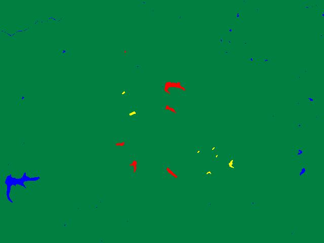
10 FIGURE 7 Using the software s pixel read-out and zoom function (Figure 8), the value range for water can be determined. The low values of 1 to 15 are obviously water but it becomes difficult to ascertain the upper value for the edge areas of the water bodies. After checking several of the water bodies an upper level value of 70 was selected. One might select a different upper level value producing slightly different results. Once this value is determined, the next step is to do a density slice classification of Band 4, the stretched version. This will be a two-level classification with the first class being water (data range 1-70) and the second class being non-water surfaces (date range ). This classification is saved as a new picture file within the software s data base. This new picture has data values of only 1s (water) and 2s (non-water). In addition to the classified image, the classification produced a count of the number of data (pixel) values associated with each class. These numbers were 2,410 and 304,790 for class 1 and 2, respectively. Figure 9 shows the classified image from the density slice classification. The color blue represents the water bodies across the image and the color green relates to all other surfaces. This classification clearly detects all of the major water surfaces within the Delaney Creek valley, not only those shown on the topographic map but also those shown on the infrared image. In addition, some of the water bodies cover larger areas than indicated on the map.
.")
11 FIGURE 8 The new classified picture file is now exported as a bitmap (.BMP) file so that it can be viewed and modified in Microsoft Paint. Load the bitmap file into Paint and edit two of the colors on the color box. Select Custom Colors under Edit Color (Figure 10). Develop two gray-tone colors by inserting the same value in each of the three boxes for red, green, and blue. The minimum and maximum value levels are 0 and 255. Do not select 1 or 2 since they already relate to the existing classes. It is best to select something like 50 and 100. Once the two new gray colors have been developed and their values known, use Paint s brush function to paint the reservoirs within the Delaney Creek valley. Use one of the gray-tone colors to paint all the reservoirs within the valley that appear on the Kossuth topographic map. Use the second gray-tone color to paint the new reservoirs within the valley that appear on the image but not the map. With the brush function this step should take less than a minute to complete. Save the modified bitmap file. Return to the image processing software and import the bitmap modified file into the software s data base as a new picture. Next, do a four-class density slice classification on the new picture. Assign the first color to the data value of 1, which now relates to all the water bodies shown on the image outside the Delaney Creek valley. Select the second color for the data value of 2, which corresponds to the non-water areas throughout the image. The last two colors are assigned to the gray-tone values used in Paint to separate the reservoirs. This density slice classification will produce a new classified image file, which will be saved in the software s data base. This picture will have values ranging
12 from 1 to 4, corresponding to the four classes. A pixel count is also generated, which in this case has 1,364 pixels for class 1 (water areas outside the valley), 304,790 pixels for class 2 (non-water bodies), 209 pixels for class 3 (the new reservoirs shown on the image), and 837 pixels for class 4 (the reservoirs shown on the topographic map). See Figure 11. These pixel values can be converted into standard area measurements (Table 2). FIGURE 9 The area measurements in Table 2 were ascertained by first determining the number of square feet in one pixel. One meter equals inches or 3.28 feet. The number of feet, 3.28, is multiplied by the number of meters along one side of a pixel, which is 28.5 for the TM data set. This calculation provides the number of feet along one side of a pixel, which is This number is squared to obtain the total number of square feet in one pixel ( ), which is then divided by 43,560, the number of square feet in an acre, to determine the proportion of an acre covered by one pixel. This proportion ( ) is finally multiplied by the number of pixels in each land cover class to obtain the number of acres in each class. For example, The number of acres in Class 1 equals: x 1,364 pixels, or acres. Multiply the number of acres by.4047 to obtain the number of hectares.

13 FIGURE 10 FIGURE 11

14 TABLE 2: TM LAND COVER RESULTS Although both data sets are the same size with respect to the number of elements and lines (640 x 480), the LISS-II data set covers a larger geographic area due to its larger pixel size. This point must be considered when examining the area measurements in Table 3. Class 1, reservoirs and other water bodies outside the Delaney Creek valley, has more area identified as water since it extends geographically beyond the area associated with the TM data set and incorporates additional water area. The same situation holds true for Class 2, non-water areas. Classes 3 and 4 are centered on the reservoirs in the Delaney Creek valley, which is situated in the middle of both data sets. Thus, the geographic difference in coverage by the two data sets should play a minor role in the area measurements for these two classes. In fact, the area measurements from both satellites are identical for Class 3, the new reservoirs. However, a 6.54 acre (2.65 hectare) difference exists for Class 4, the older reservoirs. This difference might be due to several factors. One factor might relate to the size of a pixel. The numerical value associated with a pixel is an average of the ground cell's surface reflectance. If a large portion, but not all, of a pixel covers a water surface, and thereby, generates a data value identified with water, the area of the entire pixel is then classified as water. This situation might add to the number of pixels being grouped with the water class. It is less of a problem in dealing with smaller pixels. The second factor might be due to the size of the wetlands areas found at the end of some of the older reservoirs. Determining the cut-off point between wetland areas and water areas is very difficult in a density slice classification. A different cut-off point for water might produce better results. The new reservoirs do not appear to have any major wetlands. A final factor might be the time of day when the two satellites crossed the study area. The sun elevation at the time that Landsat 5 passed over was 59 degrees; whereas, the sun elevation for the IRS-1B satellite was 70 degrees. The difference in sun elevation might create a difference in reflectance conditions. Figure 12 illustrates graphically the results of the two classifications for the Delaney Creek valley area. The results are basically identical. The TM classified image is a larger scale than the LISS-II B because it covers a smaller geographic area, and thereby, provides more detail.


15 TABLE 3: COMPARISON OF TM AND LISS-II LAND COVER RESULTS FIGURE 12 This lack of accurate and up-to-date information on the Kossuth topographic map as well as other maps could be avoided if the USGS would use satellite data on a regular basis in conjunction with aerial photography in updating maps. Water surfaces are basic map features and are, in general, easy to detect on near infrared satellite imagery. Several remote sensing satellites provide such imagery. In addition, satellite imagery gives a synoptic overview of a topographic map surface in comparison to trying to mosaic ten or more aerial photographs. Water surfaces are basic map features on topographic maps, which should be conveyed in an accurate and up-to-date manner.
16 MATERIALS AND REFERENCES: Kossuth, Indiana, United States Geological Survey 7.5 Minute Topographic Quadrangle (Map) corresponds directly with the data sets in area and clearly helps in identifying various physical and cultural features.
Geo/SAT 2 INTRODUCTION TO REMOTE SENSING
 Geo/SAT 2 INTRODUCTION TO REMOTE SENSING Paul R. Baumann, Professor Emeritus State University of New York College at Oneonta Oneonta, New York 13820 USA COPYRIGHT 2008 Paul R. Baumann Introduction Remote
Introduction to Remote Sensing
 Introduction to Remote Sensing Spatial, spectral, temporal resolutions Image display alternatives Vegetation Indices Image classifications Image change detections Accuracy assessment Satellites & Air-Photos
Digital Image Processing
 Digital Image Processing 1 Patrick Olomoshola, 2 Taiwo Samuel Afolayan 1,2 Surveying & Geoinformatic Department, Faculty of Environmental Sciences, Rufus Giwa Polytechnic, Owo. Nigeria Abstract: This paper
Remote Sensing Part 3 Examples & Applications
 Remote Sensing Part 3 Examples & Applications Review: Spectral Signatures Review: Spectral Resolution Review: Computer Display of Remote Sensing Images Individual bands of satellite data are mapped to
Land Cover Analysis to Determine Areas of Clear-cut and Forest Cover in Olney, Montana. Geob 373 Remote Sensing. Dr Andreas Varhola, Kathry De Rego
 1 Land Cover Analysis to Determine Areas of Clear-cut and Forest Cover in Olney, Montana Geob 373 Remote Sensing Dr Andreas Varhola, Kathry De Rego Zhu an Lim (14292149) L2B 17 Apr 2016 2 Abstract Montana
Lecture Series SGL 308: Introduction to Geological Mapping Lecture 8 LECTURE 8 REMOTE SENSING METHODS: THE USE AND INTERPRETATION OF SATELLITE IMAGES
 LECTURE 8 REMOTE SENSING METHODS: THE USE AND INTERPRETATION OF SATELLITE IMAGES LECTURE OUTLINE Page 8.0 Introduction 114 8.1 Objectives 115 115 8.2 Remote Sensing: Method of Operation 8.3 Importance
APCAS/10/21 April 2010 ASIA AND PACIFIC COMMISSION ON AGRICULTURAL STATISTICS TWENTY-THIRD SESSION. Siem Reap, Cambodia, April 2010
 APCAS/10/21 April 2010 Agenda Item 8 ASIA AND PACIFIC COMMISSION ON AGRICULTURAL STATISTICS TWENTY-THIRD SESSION Siem Reap, Cambodia, 26-30 April 2010 The Use of Remote Sensing for Area Estimation by Robert
Enhancement of Multispectral Images and Vegetation Indices
 Enhancement of Multispectral Images and Vegetation Indices ERDAS Imagine 2016 Description: We will use ERDAS Imagine with multispectral images to learn how an image can be enhanced for better interpretation.
Radar Imagery for Forest Cover Mapping
 Purdue University Purdue e-pubs LARS Symposia Laboratory for Applications of Remote Sensing 1-1-1981 Radar magery for Forest Cover Mapping D. J. Knowlton R. M. Hoffer Follow this and additional works at:
Spatial Analyst is an extension in ArcGIS specially designed for working with raster data.
 Spatial Analyst is an extension in ArcGIS specially designed for working with raster data. 1 Do you remember the difference between vector and raster data in GIS? 2 In Lesson 2 you learned about the difference
A map says to you, 'Read me carefully, follow me closely, doubt me not.' It says, 'I am the Earth in the palm of your hand. Without me, you are alone
 A map says to you, 'Read me carefully, follow me closely, doubt me not.' It says, 'I am the Earth in the palm of your hand. Without me, you are alone and lost. Beryl Markham (West With the Night, 1946
AmericaView EOD 2016 page 1 of 16
 Remote Sensing Flood Analysis Lesson Using MultiSpec Online By Larry Biehl Systems Manager, Purdue Terrestrial Observatory (biehl@purdue.edu) v Objective The objective of these exercises is to analyze
Aerial Photo Interpretation
 Aerial Photo Interpretation Aerial Photo Interpretation To date, course has focused on skills of photogrammetry Scale Distance Direction Area Height There s another side to Aerial Photography: Interpretation
COMPARISON OF INFORMATION CONTENTS OF HIGH RESOLUTION SPACE IMAGES
 COMPARISON OF INFORMATION CONTENTS OF HIGH RESOLUTION SPACE IMAGES H. Topan*, G. Büyüksalih*, K. Jacobsen ** * Karaelmas University Zonguldak, Turkey ** University of Hannover, Germany htopan@karaelmas.edu.tr,
Sommersemester Prof. Dr. Christoph Kleinn Institut für Waldinventur und Waldwachstum Arbeitsbereich Fernerkundung und Waldinventur.
 Basics of Remote Sensing Some literature references Franklin, SE 2001 Remote Sensing for Sustainable Forest Management Lewis Publishers 407p Lillesand, Kiefer 2000 Remote Sensing and Image Interpretation
Exploring the Earth with Remote Sensing: Tucson
 Exploring the Earth with Remote Sensing: Tucson Project ASTRO Chile March 2006 1. Introduction In this laboratory you will explore Tucson and its surroundings with remote sensing. Remote sensing is the
Preparing Remote Sensing Data for Natural Resources Mapping (image enhancement, rectifications )
") Preparing Remote Sensing Data for Natural Resources Mapping (image enhancement, rectifications ) Why is this important What are the major approaches Examples of digital image enhancement Follow up exercises
Preparing Remote Sensing Data for Natural Resources Mapping (image enhancement, rectifications ) Why is this important What are the major approaches Examples of digital image enhancement Follow up exercises
First Exam: Thurs., Sept 28
 8 Geographers Tools: Gathering Information Prof. Anthony Grande Hunter College Geography Lecture design, content and presentation AFG 0917. Individual images and illustrations may be subject to prior copyright.
First Exam. Geographers Tools: Gathering Information. Photographs and Imagery. SPIN 2 Image of Downtown Atlanta, GA 1995 REMOTE SENSING 9/19/2016
 First Exam Geographers Tools: Gathering Information Prof. Anthony Grande Hunter College Geography Lecture design, content and presentation AFG 0616. Individual images and illustrations may be subject to
Land Cover Change Analysis An Introduction to Land Cover Change Analysis using the Multispectral Image Data Analysis System (MultiSpec )
") Land Cover Change Analysis An Introduction to Land Cover Change Analysis using the Multispectral Image Data Analysis System (MultiSpec ) Level: Grades 9 to 12 Windows version With Teacher Notes Earth Observation
Land Cover Change Analysis An Introduction to Land Cover Change Analysis using the Multispectral Image Data Analysis System (MultiSpec ) Level: Grades 9 to 12 Windows version With Teacher Notes Earth Observation
CanImage. (Landsat 7 Orthoimages at the 1: Scale) Standards and Specifications Edition 1.0
 Standards and Specifications Edition 1.0") CanImage (Landsat 7 Orthoimages at the 1:50 000 Scale) Standards and Specifications Edition 1.0 Centre for Topographic Information Customer Support Group 2144 King Street West, Suite 010 Sherbrooke, QC
CanImage (Landsat 7 Orthoimages at the 1:50 000 Scale) Standards and Specifications Edition 1.0 Centre for Topographic Information Customer Support Group 2144 King Street West, Suite 010 Sherbrooke, QC
Lecture 13: Remotely Sensed Geospatial Data
 Lecture 13: Remotely Sensed Geospatial Data A. The Electromagnetic Spectrum: The electromagnetic spectrum (Figure 1) indicates the different forms of radiation (or simply stated light) emitted by nature.
Urban Classification of Metro Manila for Seismic Risk Assessment using Satellite Images
 Urban Classification of Metro Manila for Seismic Risk Assessment using Satellite Images Fumio YAMAZAKI/ yamazaki@edm.bosai.go.jp Hajime MITOMI/ mitomi@edm.bosai.go.jp Yalkun YUSUF/ yalkun@edm.bosai.go.jp
Exercise 4-1 Image Exploration
 Exercise 4-1 Image Exploration With this exercise, we begin an extensive exploration of remotely sensed imagery and image processing techniques. Because remotely sensed imagery is a common source of data
Introduction. Introduction. Introduction. Introduction. Introduction
 Identifying habitat change and conservation threats with satellite imagery Extinction crisis Volker Radeloff Department of Forest Ecology and Management Extinction crisis Extinction crisis Conservationists
Blacksburg, VA July 24 th 30 th, 2010 Remote Sensing Page 1. A condensed overview. For our purposes
 A condensed overview George McLeod Prepared by: With support from: NSF DUE-0903270 in partnership with: Geospatial Technician Education Through Virginia s Community Colleges (GTEVCC) The art and science
REMOTE SENSING INTERPRETATION
 REMOTE SENSING INTERPRETATION Jan Clevers Centre for Geo-Information - WU Remote Sensing --> RS Sensor at a distance EARTH OBSERVATION EM energy Earth RS is a tool; one of the sources of information! 1
INTRODUCTORY REMOTE SENSING. Geob 373
 INTRODUCTORY REMOTE SENSING Geob 373 Landsat 7 15 m image highlighting the geology of Oman http://www.satimagingcorp.com/gallery-landsat.html ASTER 15 m SWIR image, Escondida Mine, Chile http://www.satimagingcorp.com/satellite-sensors/aster.html
Contents Remote Sensing for Studying Earth Surface and Changes
 Contents Remote Sensing for Studying Earth Surface and Changes Anupma Prakash Day : Tuesday Date : September 26, 2008 Audience : AMIDST Participants What is remote sensing? How does remote sensing work?
Apply Colour Sequences to Enhance Filter Results. Operations. What Do I Need? Filter
 Apply Colour Sequences to Enhance Filter Results Operations What Do I Need? Filter Single band images from the SPOT and Landsat platforms can sometimes appear flat (i.e., they are low contrast images).
MSB Imagery Program FAQ v1
 MSB Imagery Program FAQ v1 (F)requently (A)sked (Q)uestions 9/22/2016 This document is intended to answer commonly asked questions related to the MSB Recurring Aerial Imagery Program. Table of Contents
First Exam: New Date. 7 Geographers Tools: Gathering Information. Photographs and Imagery REMOTE SENSING 2/23/2018. Friday, March 2, 2018.
 First Exam: New Date Friday, March 2, 2018. Combination of multiple choice questions and map interpretation. Bring a #2 pencil with eraser. Based on class lectures supplementing chapter 1. Review lecture
REMOTE SENSING. Topic 10 Fundamentals of Digital Multispectral Remote Sensing MULTISPECTRAL SCANNERS MULTISPECTRAL SCANNERS
 REMOTE SENSING Topic 10 Fundamentals of Digital Multispectral Remote Sensing Chapter 5: Lillesand and Keifer Chapter 6: Avery and Berlin MULTISPECTRAL SCANNERS Record EMR in a number of discrete portions
Remote Sensing. The following figure is grey scale display of SPOT Panchromatic without stretching.
 Remote Sensing Objectives This unit will briefly explain display of remote sensing image, geometric correction, spatial enhancement, spectral enhancement and classification of remote sensing image. At
Interpreting land surface features. SWAC module 3
 Interpreting land surface features SWAC module 3 Interpreting land surface features SWAC module 3 Different kinds of image Panchromatic image True-color image False-color image EMR : NASA Echo the bat
NRS 415 Remote Sensing of Environment
 NRS 415 Remote Sensing of Environment 1 High Oblique Perspective (Side) Low Oblique Perspective (Relief) 2 Aerial Perspective (See What s Hidden) An example of high spatial resolution true color remote
Geo/SAT 2 TROPICAL WET REALMS OF CENTRAL AFRICA, PART II
 Geo/SAT 2 TROPICAL WET REALMS OF CENTRAL AFRICA, PART II Paul R. Baumann Professor of Geography (Emeritus) State University of New York College at Oneonta Oneonta, New York 13820 USA COPYRIGHT 2009 Paul
Due Date: September 22
 Geography 309 Lab 1 Page 1 LAB 1: INTRODUCTION TO REMOTE SENSING Due Date: September 22 Objectives To familiarize yourself with: o remote sensing resources on the Internet o some remote sensing sensors
Spectral Signatures. Vegetation. 40 Soil. Water WAVELENGTH (microns)
") Spectral Signatures % REFLECTANCE VISIBLE NEAR INFRARED Vegetation Soil Water.5. WAVELENGTH (microns). Spectral Reflectance of Urban Materials 5 Parking Lot 5 (5=5%) Reflectance 5 5 5 5 5 Wavelength (nm)
Spectral Signatures % REFLECTANCE VISIBLE NEAR INFRARED Vegetation Soil Water.5. WAVELENGTH (microns). Spectral Reflectance of Urban Materials 5 Parking Lot 5 (5=5%) Reflectance 5 5 5 5 5 Wavelength (nm)
Chapter 1 Overview of imaging GIS
 Chapter 1 Overview of imaging GIS Imaging GIS, a term used in the medical imaging community (Wang 2012), is adopted here to describe a geographic information system (GIS) that displays, enhances, and facilitates
SEMI-SUPERVISED CLASSIFICATION OF LAND COVER BASED ON SPECTRAL REFLECTANCE DATA EXTRACTED FROM LISS IV IMAGE
 SEMI-SUPERVISED CLASSIFICATION OF LAND COVER BASED ON SPECTRAL REFLECTANCE DATA EXTRACTED FROM LISS IV IMAGE B. RayChaudhuri a *, A. Sarkar b, S. Bhattacharyya (nee Bhaumik) c a Department of Physics,
Module 4, Investigation 2: Log 1 What features do archaeologists look for on an image?
 What are the seven elements used by geoarchaeologists to analyze and interpret remotely sensed images? Geoarchaeologists face several issues when using remotely sensed images. They must determine the location
REMOTE SENSING OF RIVERINE WATER BODIES
 REMOTE SENSING OF RIVERINE WATER BODIES Bryony Livingston, Paul Frazier and John Louis Farrer Research Centre Charles Sturt University Wagga Wagga, NSW 2678 Ph 02 69332317, Fax 02 69332737 blivingston@csu.edu.au
Mod. 2 p. 1. Prof. Dr. Christoph Kleinn Institut für Waldinventur und Waldwachstum Arbeitsbereich Fernerkundung und Waldinventur
 Histograms of gray values for TM bands 1-7 for the example image - Band 4 and 5 show more differentiation than the others (contrast=the ratio of brightest to darkest areas of a landscape). - Judging from
Module 11 Digital image processing
 Introduction Geo-Information Science Practical Manual Module 11 Digital image processing 11. INTRODUCTION 11-1 START THE PROGRAM ERDAS IMAGINE 11-2 PART 1: DISPLAYING AN IMAGE DATA FILE 11-3 Display of
An Introduction to Geomatics. Prepared by: Dr. Maher A. El-Hallaq خاص بطلبة مساق مقدمة في علم. Associate Professor of Surveying IUG
 An Introduction to Geomatics خاص بطلبة مساق مقدمة في علم الجيوماتكس Prepared by: Dr. Maher A. El-Hallaq Associate Professor of Surveying IUG 1 Airborne Imagery Dr. Maher A. El-Hallaq Associate Professor
PROCEEDINGS - AAG MIDDLE STATES DIVISION - VOL. 21, 1988
 PROCEEDINGS - AAG MIDDLE STATES DIVISION - VOL. 21, 1988 SPOTTING ONEONTA: A COMPARISON OF SPOT 1 AND landsat 1 IN DETECTING LAND COVER PATTERNS IN A SMALL URBAN AREA Paul R. Baumann Department of Geography
An Introduction to Remote Sensing & GIS. Introduction
 An Introduction to Remote Sensing & GIS Introduction Remote sensing is the measurement of object properties on Earth s surface using data acquired from aircraft and satellites. It attempts to measure something
White Paper. Medium Resolution Images and Clutter From Landsat 7 Sources. Pierre Missud
 White Paper Medium Resolution Images and Clutter From Landsat 7 Sources Pierre Missud Medium Resolution Images and Clutter From Landsat7 Sources Page 2 of 5 Introduction Space technologies have long been
to Geospatial Technologies
 What s in a Pixel? A Primer for Remote Sensing What s in a Pixel Development UNH Cooperative Extension Geospatial Technologies Training Center Shane Bradt UConn Cooperative Extension Geospatial Technology
Module 3 Introduction to GIS. Lecture 8 GIS data acquisition
 Module 3 Introduction to GIS Lecture 8 GIS data acquisition GIS workflow Data acquisition (geospatial data input) GPS Remote sensing (satellites, UAV s) LiDAR Digitized maps Attribute Data Management Data
Visualizing a Pixel. Simulate a Sensor s View from Space. In this activity, you will:
 Simulate a Sensor s View from Space In this activity, you will: Measure and mark pixel boundaries Learn about spatial resolution, pixels, and satellite imagery Classify land cover types Gain exposure to
How to Access Imagery and Carry Out Remote Sensing Analysis Using Landsat Data in a Browser
 How to Access Imagery and Carry Out Remote Sensing Analysis Using Landsat Data in a Browser Including Introduction to Remote Sensing Concepts Based on: igett Remote Sensing Concept Modules and GeoTech
Using Color-Infrared Imagery for Impervious Surface Analysis. Chris Behee City of Bellingham Planning & Community Development
 Using Color-Infrared Imagery for Impervious Surface Analysis. Chris Behee City of Bellingham Planning & Community Development NW GIS Users Group - March 18, 2005 Outline What is Color Infrared Imagery?
CHAPTER 7: Multispectral Remote Sensing
 CHAPTER 7: Multispectral Remote Sensing REFERENCE: Remote Sensing of the Environment John R. Jensen (2007) Second Edition Pearson Prentice Hall Overview of How Digital Remotely Sensed Data are Transformed
In late April of 1986 a nuclear accident damaged a reactor at the Chernobyl nuclear
 CHERNOBYL NUCLEAR POWER PLANT ACCIDENT Long Term Effects on Land Use Patterns Project Introduction: In late April of 1986 a nuclear accident damaged a reactor at the Chernobyl nuclear power plant in Ukraine.
Remote Sensing for Rangeland Applications
 Remote Sensing for Rangeland Applications Jay Angerer Ecological Training June 16, 2012 Remote Sensing The term "remote sensing," first used in the United States in the 1950s by Ms. Evelyn Pruitt of the
Digital Image Processing - A Remote Sensing Perspective
 ISSN 2278 0211 (Online) Digital Image Processing - A Remote Sensing Perspective D.Sarala Department of Physics & Electronics St. Ann s College for Women, Mehdipatnam, Hyderabad, India Sunita Jacob Head,
FOR 353: Air Photo Interpretation and Photogrammetry. Lecture 2. Electromagnetic Energy/Camera and Film characteristics
 FOR 353: Air Photo Interpretation and Photogrammetry Lecture 2 Electromagnetic Energy/Camera and Film characteristics Lecture Outline Electromagnetic Radiation Theory Digital vs. Analog (i.e. film ) Systems
GIS Data Collection. Remote Sensing
 GIS Data Collection Remote Sensing Data Collection Remote sensing Introduction Concepts Spectral signatures Resolutions: spectral, spatial, temporal Digital image processing (classification) Other systems
2017 REMOTE SENSING EVENT TRAINING STRATEGIES 2016 SCIENCE OLYMPIAD COACHING ACADEMY CENTERVILLE, OH
 2017 REMOTE SENSING EVENT TRAINING STRATEGIES 2016 SCIENCE OLYMPIAD COACHING ACADEMY CENTERVILLE, OH This presentation was prepared using draft rules. There may be some changes in the final copy of the
A (very) brief introduction to Remote Sensing: From satellites to maps!
 brief introduction to Remote Sensing: From satellites to maps!") Spatial Data Analysis and Modeling for Agricultural Development, with R - Workshop A (very) brief introduction to Remote Sensing: From satellites to maps! Earthlights DMSP 1994-1995 https://wikimedia.org/
Spatial Data Analysis and Modeling for Agricultural Development, with R - Workshop A (very) brief introduction to Remote Sensing: From satellites to maps! Earthlights DMSP 1994-1995 https://wikimedia.org/
Remote Sensing. Measuring an object from a distance. For GIS, that means using photographic or satellite images to gather spatial data
 Remote Sensing Measuring an object from a distance For GIS, that means using photographic or satellite images to gather spatial data Remote Sensing measures electromagnetic energy reflected or emitted
Lab #4 Topographic Maps and Aerial Photographs
 Lab #4 Topographic Maps and Aerial Photographs Purpose To familiarize you with using topographic maps. Visualizing the shape of landforms from topographic maps is an essential skill in geology. Proficiency
Introduction of Satellite Remote Sensing
 Introduction of Satellite Remote Sensing Spatial Resolution (Pixel size) Spectral Resolution (Bands) Resolutions of Remote Sensing 1. Spatial (what area and how detailed) 2. Spectral (what colors bands)
Land cover change methods. Ned Horning
 Land cover change methods Ned Horning Version: 1.0 Creation Date: 2004-01-01 Revision Date: 2004-01-01 License: This document is licensed under a Creative Commons Attribution-Share Alike 3.0 Unported License.
REMOTE SENSING FOR FLOOD HAZARD STUDIES.
 REMOTE SENSING FOR FLOOD HAZARD STUDIES. OPTICAL SENSORS. 1 DRS. NANETTE C. KINGMA 1 Optical Remote Sensing for flood hazard studies. 2 2 Floods & use of remote sensing. Floods often leaves its imprint
University of Texas at San Antonio EES 5053 Term Project CORRELATION BETWEEN NDVI AND SURFACE TEMPERATURES USING LANDSAT ETM + IMAGERY NEWFEL MAZARI
 University of Texas at San Antonio EES 5053 Term Project CORRELATION BETWEEN NDVI AND SURFACE TEMPERATURES USING LANDSAT ETM + IMAGERY NEWFEL MAZARI Introduction and Objectives The present study is a correlation
The (False) Color World
 Color World") There s more to the world than meets the eye In this activity, your group will explore: The Value of False Color Images Different Types of Color Images The Use of Contextual Clues for Feature Identification
There s more to the world than meets the eye In this activity, your group will explore: The Value of False Color Images Different Types of Color Images The Use of Contextual Clues for Feature Identification
Remote Sensing. in Agriculture. Dr. Baqer Ramadhan CRP 514 Geographic Information System. Adel M. Al-Rebh G Term Paper.
 Remote Sensing in Agriculture Term Paper to Dr. Baqer Ramadhan CRP 514 Geographic Information System By Adel M. Al-Rebh G199325390 May 2012 Table of Contents 1.0 Introduction... 4 2.0 Objective... 4 3.0
Important Missions. weather forecasting and monitoring communication navigation military earth resource observation LANDSAT SEASAT SPOT IRS
 Fundamentals of Remote Sensing Pranjit Kr. Sarma, Ph.D. Assistant Professor Department of Geography Mangaldai College Email: prangis@gmail.com Ph. No +91 94357 04398 Remote Sensing Remote sensing is defined
NON-PHOTOGRAPHIC SYSTEMS: Multispectral Scanners Medium and coarse resolution sensor comparisons: Landsat, SPOT, AVHRR and MODIS
 NON-PHOTOGRAPHIC SYSTEMS: Multispectral Scanners Medium and coarse resolution sensor comparisons: Landsat, SPOT, AVHRR and MODIS CLASSIFICATION OF NONPHOTOGRAPHIC REMOTE SENSORS PASSIVE ACTIVE DIGITAL
Image interpretation I and II
 Image interpretation I and II Looking at satellite image, identifying different objects, according to scale and associated information and to communicate this information to others is what we call as IMAGE
RGB colours: Display onscreen = RGB
 RGB colours: http://www.colorspire.com/rgb-color-wheel/ Display onscreen = RGB DIGITAL DATA and DISPLAY Myth: Most satellite images are not photos Photographs are also 'images', but digital images are
Land Cover Change Analysis An Introduction to Land Cover Change Analysis using the Multispectral Image Data Analysis System (MultiSpec )
") Land Cover Change Analysis An Introduction to Land Cover Change Analysis using the Multispectral Image Data Analysis System (MultiSpec ) Level: Grades 9 to 12 Macintosh version Earth Observation Day Tutorial
Land Cover Change Analysis An Introduction to Land Cover Change Analysis using the Multispectral Image Data Analysis System (MultiSpec ) Level: Grades 9 to 12 Macintosh version Earth Observation Day Tutorial
Keywords: Agriculture, Olive Trees, Supervised Classification, Landsat TM, QuickBird, Remote Sensing.
 Classification of agricultural fields by using Landsat TM and QuickBird sensors. The case study of olive trees in Lesvos island. Christos Vasilakos, University of the Aegean, Department of Environmental
Lesson 3: Working with Landsat Data
 Lesson 3: Working with Landsat Data Lesson Description The Landsat Program is the longest-running and most extensive collection of satellite imagery for Earth. These datasets are global in scale, continuously
7 Geographers Tools: Gathering Information
 FIRST EXAM TODAY ExCr ATLAS EXERCISE for EXAM I is DUE. Bubble in your vtues., Feb. 26, 2019. Pass Scantrons forward. name on the back. Combination of multiple choice questions and map interpretation.
High Resolution Sensor Test Comparison with SPOT, KFA1000, KVR1000, IRS-1C and DPA in Lower Saxony
 High Resolution Sensor Test Comparison with SPOT, KFA1000, KVR1000, IRS-1C and DPA in Lower Saxony K. Jacobsen, G. Konecny, H. Wegmann Abstract The Institute for Photogrammetry and Engineering Surveys
Preserving the Past: The Development of a Digital Historical Aerial Photography Archive
 DONALD E. LUMAN Preserving the Past: The Development of a Digital Historical Aerial Photography Archive The University of Illinois Map and Geography Library maintains a collection of approximately 60,000
FOR 474: Forest Inventory. FOR 474: Forest Inventory. Why do we Care About Forest Sampling?
 FOR 474: Forest Inventory 1. Advanced Forest Inventory The Need for Forest Sampling Brief Intro to Remote Sensing and GIS Readings: FOR 474: Forest Inventory Related Courses! FOR 274: Forest Measurements
Abstract Quickbird Vs Aerial photos in identifying man-made objects
 Abstract Quickbird Vs Aerial s in identifying man-made objects Abdullah Mah abdullah.mah@aramco.com Remote Sensing Group, emap Division Integrated Solutions Services Department (ISSD) Saudi Aramco, Dhahran
EXAMPLES OF TOPOGRAPHIC MAPS PRODUCED FROM SPACE AND ACHIEVED ACCURACY CARAVAN Workshop on Mapping from Space, Phnom Penh, June 2000
 EXAMPLES OF TOPOGRAPHIC MAPS PRODUCED FROM SPACE AND ACHIEVED ACCURACY CARAVAN Workshop on Mapping from Space, Phnom Penh, June 2000 Jacobsen, Karsten University of Hannover Email: karsten@ipi.uni-hannover.de
Introduction to Remote Sensing Part 1
 Introduction to Remote Sensing Part 1 A Primer on Electromagnetic Radiation Digital, Multi-Spectral Imagery The 4 Resolutions Displaying Images Corrections and Enhancements Passive vs. Active Sensors Radar
Application of Satellite Imagery for Rerouting Electric Power Transmission Lines
 Application of Satellite Imagery for Rerouting Electric Power Transmission Lines T. LUEMONGKOL 1, A. WANNAKOMOL 2 & T. KULWORAWANICHPONG 1 1 Power System Research Unit, School of Electrical Engineering
Introduction to Remote Sensing Fundamentals of Satellite Remote Sensing. Mads Olander Rasmussen
 Introduction to Remote Sensing Fundamentals of Satellite Remote Sensing Mads Olander Rasmussen (mora@dhi-gras.com) 01. Introduction to Remote Sensing DHI What is remote sensing? the art, science, and technology
Remote sensing in archaeology from optical to lidar. Krištof Oštir ModeLTER Scientific Research Centre of the Slovenian Academy of Sciences and Arts
 Remote sensing in archaeology from optical to lidar Krištof Oštir ModeLTER Scientific Research Centre of the Slovenian Academy of Sciences and Arts Introduction Optical remote sensing Systems Search for
Remote Sensing Platforms
 Types of Platforms Lighter-than-air Remote Sensing Platforms Free floating balloons Restricted by atmospheric conditions Used to acquire meteorological/atmospheric data Blimps/dirigibles Major role - news
Black Dot shows actual Point location
 207 Plate 1 Use of scanned archive aerial photographs, digital photogrammetry and GIS to plot river channel erosion along the Afon Trannon, Wales (part of the study by Mount et al 2000, 2003). Plate 2
Digital database creation of historical Remote Sensing Satellite data from Film Archives A case study
 Digital database creation of historical Remote Sensing Satellite data from Film Archives A case study N.Ganesh Kumar +, E.Venkateswarlu # Product Quality Control, Data Processing Area, NRSA, Hyderabad.
Documenting Land Cover and Vegetation Productivity Changes in the NWT using the Landsat Satellite Archive
 Documenting Land Cover and Vegetation Productivity Changes in the NWT using the Landsat Satellite Archive Fraser, R.H 1, Olthof, I. 1, Deschamps, A. 1, Pregitzer, M. 1, Kokelj, S. 2, Lantz, T. 3,Wolfe,
Saturation And Value Modulation (SVM): A New Method For Integrating Color And Grayscale Imagery
: A New Method For Integrating Color And Grayscale Imagery") 87 Saturation And Value Modulation (SVM): A New Method For Integrating Color And Grayscale Imagery By David W. Viljoen 1 and Jeff R. Harris 2 Geological Survey of Canada 615 Booth St. Ottawa, ON, K1A 0E9
87 Saturation And Value Modulation (SVM): A New Method For Integrating Color And Grayscale Imagery By David W. Viljoen 1 and Jeff R. Harris 2 Geological Survey of Canada 615 Booth St. Ottawa, ON, K1A 0E9
Application of GIS to Fast Track Planning and Monitoring of Development Agenda
 Application of GIS to Fast Track Planning and Monitoring of Development Agenda Radiometric, Atmospheric & Geometric Preprocessing of Optical Remote Sensing 13 17 June 2018 Outline 1. Why pre-process remotely
Aerial photography and Remote Sensing. Bikini Atoll, 2013 (60 years after nuclear bomb testing)
") Aerial photography and Remote Sensing Bikini Atoll, 2013 (60 years after nuclear bomb testing) Computers have linked mapping techniques under the umbrella term : Geomatics includes all the following spatial
Aerial photography and Remote Sensing Bikini Atoll, 2013 (60 years after nuclear bomb testing) Computers have linked mapping techniques under the umbrella term : Geomatics includes all the following spatial
Separation of crop and vegetation based on Digital Image Processing
 Separation of crop and vegetation based on Digital Image Processing Mayank Singh Sakla 1, Palak Jain 2 1 M.TECH GEOMATICS student, CEPT UNIVERSITY 2 M.TECH GEOMATICS student, CEPT UNIVERSITY Word Limit
CHAPTER 5. Image Interpretation
 CHAPTER 5 Image Interpretation Introduction To translate images into information, we must apply a specialized knowlage, image interpretation, which we can apply to derive useful information from the raw
USING LANDSAT MULTISPECTRAL IMAGES IN ANALYSING FOREST VEGETATION
 Technical Sciences 243 USING LANDSAT MULTISPECTRAL IMAGES IN ANALYSING FOREST VEGETATION Teodor TODERA teotoderas@yahoo.com Traian CR CEA traiancracea@yahoo.com Alina NEGOESCU alina.negoescu@yahoo.com
Supervised Land Cover Classification An introduction to digital image classification using the Multispectral Image Data Analysis System (MultiSpec )
") Supervised Land Cover Classification An introduction to digital image classification using the Multispectral Image Data Analysis System (MultiSpec ) Level: Grades 9 to 12 Windows version With Teacher Notes
Supervised Land Cover Classification An introduction to digital image classification using the Multispectral Image Data Analysis System (MultiSpec ) Level: Grades 9 to 12 Windows version With Teacher Notes
Govt. Engineering College Jhalawar Model Question Paper Subject- Remote Sensing & GIS
 Govt. Engineering College Jhalawar Model Question Paper Subject- Remote Sensing & GIS Time: Max. Marks: Q1. What is remote Sensing? Explain the basic components of a Remote Sensing system. Q2. What is
Monitoring agricultural plantations with remote sensing imagery
 MPRA Munich Personal RePEc Archive Monitoring agricultural plantations with remote sensing imagery Camelia Slave and Anca Rotman University of Agronomic Sciences and Veterinary Medicine - Bucharest Romania,