Welcome! Bill of Materials
|
|
|
- Amos Lloyd
- 5 years ago
- Views:
Transcription

1 Welcome! Congratulations! You ve just taken one of your first steps into the world of 3D Laser Engraving! This guide will take you through the steps of installing Opt Laser s PLH3D 6W engraving laser head onto your X-Carve! We ve tried to make it as easy as possible to get you from unpacking your parts to engraving. The PLH3D engraving laser head allows you to engrave or cut your designs in a wide variety of materials such as wood, plastic, rubber, foam, cardboard, leather and many more. Bill of Materials This is all you need to have in order to get your X-Carve upgraded with Opt Laser s PLH3D 6W laser engraving head: From the left: 1) 12V 3A power supply 2) PLH3D nozzle & 43mm spindle holder adapter with screws (optional) 3) PLH3D engraving laser head 4) Additional nm collimator
 of 0,5 mm2 (20 AWG) 4-core wire to carry power and control signals from power supply and")

2 Aside from the kit purchased at OptLasers.com you will need regular 3-core household wire with a plug for the power adapter and 2,4m (95") of 0,5 mm2 (20 AWG) 4-core wire to carry power and control signals from power supply and X-Controller to the laser head: Getting Started We recommend to swap X-Carve s spindle and replace it with a laser for the laser engraving tasks. It is really easy to do and takes almost no time at all. By doing so you will minimize the risk of dust getting into your laser head and optics while carving with the spindle and having the laser head mounted right beside it. It is of course possible to mount the laser head directly on the Z-axis however, not recommended. Before wiring the laser up we could cut our own laser head mount using the X-Carve:

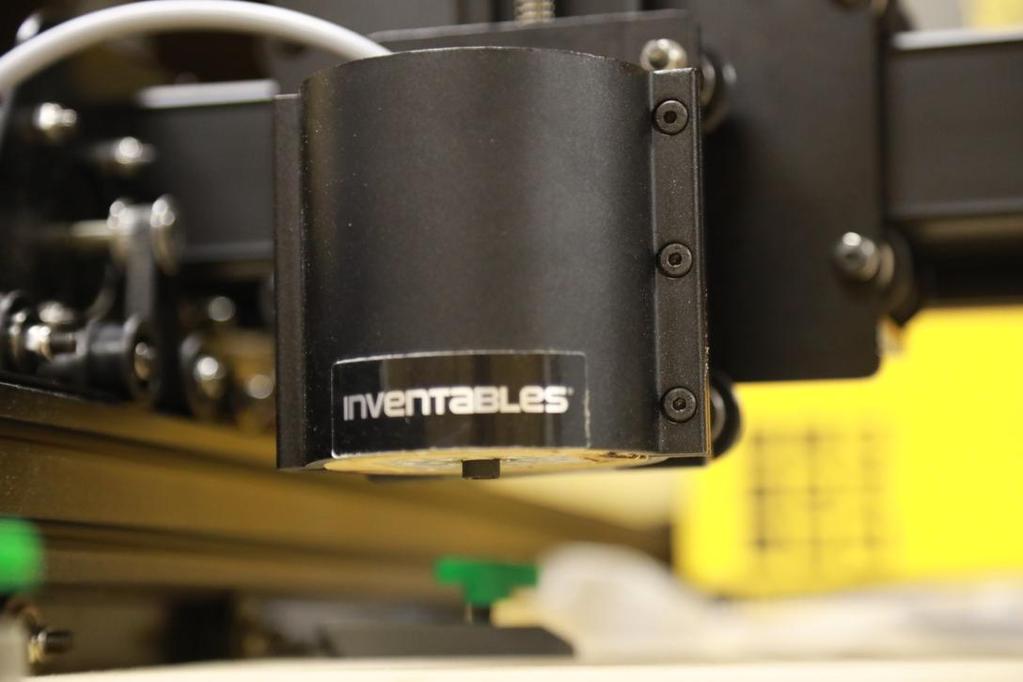
3 The mount's outer diameter is 68 mm (the same as DeWalt s 611 or D26200 spindle) The square inside is 40,1mm x 40,1mm and positioned 5mm off-center to account for aluminum protective can on the laser head. This can protect the laser driver which is mounted directly on the laser head. Easel project for this mount can be found here: Here's how the laser head looks with the mount: To mount the laser head in the spindle holder, loosen 3 spindle clamp screws and take the spindle out. Insert the laser holder into the spindle mount, push it all the way down, to the bottom and re-tighten the clamp screws. Push the laser head into the holder. The holder is designed for a tight fit with the laser head. The opening is only 0,1mm bigger than the laser head itself. Once installed it should look like this:


4

5 Wiring Feed the 4-core wire through the drag chain and connect it to the laser head using the terminal block (included): On the picture, the red and black wires are going to the power supply. Green and white wires are going to X-Controller. Recommended wiring: Laser Head Brown (12V) Green (Ground) Yellow (Analog/PWM Ground) White (Analog/PWM In) 4-core wire Red Black White Green Wire up the power supply. First connect the mains lead: brown to L, Blue to N, yellow/green to earth. Next, connect red wire coming from the 4-core wire to V+ terminal and black to V- terminal. It should look like this:

")
6 Connect green and white wires from the 4-core wire to the X-Controller. Green wire goes to Spindle (PWM) and white wire goes to GND:

7 PLH3D nozzle & 43mm spindle holder adapter It is recommended to use an additional nozzle while performing cuts with PLH3D laser head. The nozzle will direct the air stream much better in cases where the laser head is position more than 50 mm from material surface. Here s how the nozzle looks like: Nozzle attaches directly to the laser head with 4 attached screws. Here s a photo of a laser head with the nozzle attached:


8 The nozzle can also be used as a mount if your X-Carve has the stock 43mm 24V spindle. If your X-Carve was delivered with DeWalt 611 or D26200 trim router, you ll have to either use the mount described Getting started chapter of this guide or cut another one that fits the nozzle only, just like the one on picture below: Easel project for this mount can be found here: This is how PLH3D laser head with the nozzle fits into the mount and the X-Carve:


9
 signal has to be enabled. There is few ways to do that but we will focus on the most user friendly one. Go to Easel s setup (http://easel.")
10 Setup Congratulations! Your X-Carve is now upgraded with 3D engraving laser head. Before you can use it however, you will have to set-up your X-Carve first. In order for the laser head to work the Spindle (PWM) signal has to be enabled. There is few ways to do that but we will focus on the most user friendly one. Go to Easel s setup ( and choose the correct settings for your machine. The setup is probably similar to this: Change your Spindle from DeWalt 611 to Other and set maximum RPM to (or 255). Continue with the setup procedure until you get to Spindle Settings screen:
11 Set "Spindle control preference" to "Automatic" and click "Save spindle preference". Proceed to the end of the setup procedure. The spindle control is now enabled and X-Controller can control the laser head. Keep in mind that Easel software is not meant to work with laser heads and it will not work properly. You need to prepare your g-code using Opt Laser s G-Code Generator software (or other software). Once you have your G-Code ready you may use Easel, Universal Gcode Sender or Chillipeppr to send it to your X-Carve. First engraving Finally, it s time to fire up the laser and engrave something. G-Code commands to operate the laser are: 1) M3 S<value> - this command turns the laser on and expects a value between 0 and (or 255 depends on the RPM value entered during the setup). This value defines the power of the laser, for example M3 S6000 (M3 S127) Will turn the laser on with 50% power. 2) M5 (or M3 S0) this command turns the laser off. Keep in mind that when the laser is in use, Z-axis should remain stationary to preserve laser s focus. Let s start with a simple logo:

12 G-Code for this logo is available here: LINK to PLH3D_logo.g Here s the result on scrap piece of MDF:


13 Congratulations!
14 You're all set. Now you can use your X-Carve to laser-cut and laser-engrave your projects. Once you're done with the laser head and want to swap it with the spindle, remember to unplug the Spindle (PWM) connector from X-Controller to avoid shorts. Safety Note: Looking at the laser beam may irreversibly damage your sight. Opt Laser offers 445nm protective googles. Always wear protective gear when working with lasers.
Installing the 3 Indexer: PRS Standard Tools
 888-680-4466 ShopBotTools.com Installing the 3 Indexer: PRS Standard Tools Copyright 2016 ShopBot Tools, Inc. page 1 Copyright 2016 ShopBot Tools, Inc. page 2 Table of Contents Route Cable into Box...5
CNC Router. Cnc Course
 CNC Router A CNC Router is a computer numerically-controlled machine where the tool paths are controlled via computer. It can cut and mill various hard materials, such as wood, composites, aluminium, plastics,
T R U E. Start by building the example boat, then turn it into your own unique design.
 T R U E Start by building the example boat, then turn it into your own unique design. For use with TeacherGeek Build-a-Boat Activity, or Maker Cart. To find documents and activity materials, click here.
E3 CNC Router Assembly Instructions
 E3 CNC Router Assembly Instructions Specifications... 3 Getting Started... 3 Safety First... 3 Required Tools... 4 Building the E3 CNC Engraver... 4 1. Z Spindle Mount Assembly... 5 3. Frame Assembly...
Service Manual for XLE/XLT Series Laser Engravers
 Service Manual for XLE/XLT Series Laser Engravers Table of Contents Maintenance...1 Beam alignment...3 Auto focus alignment...8 Bridge alignment...10 Electronics panel replacement...11 X motor change...12
-Eagle Edger Jr Linear Edge Add-on for the Blue Ripper Jr
 -Eagle Edger Jr Linear Edge Add-on for the Blue Ripper Jr (Blade shown might not ship with tool, or be available.) Operation, Safety, and Instruction Manual v20150521 Page 2 Operating/Safety Instructions
Carvey Quick Start & Resource Guide
 Carvey Quick Start & Resource Guide Carvey Manual and Guide Carvey FAQs: https://inventables.desk.com/customer/en/portal/topics/820856-carveyfaq/articles?b_id=9565 Carvey Manual: http://carvey-instructions.inventables.com
PLH3D-6W Series Operating Manual
 1 PLH3D-6W Series Operating Manual Contact and Shipping: Company Information: Tomorrow's System Sp. Z o.o. Tomorrow's System Sp. Z o.o. Okulickiego 7/9 hala G39 Pułaskiego 125/35 05-500 Piaseczno 15-337
HQ Pole Upgrade Kit for HQ Adjustable Table and HQ QuilTable Assembly Instructions 1
 HQ Pole Upgrade Kit for HQ Adjustable Table and HQ QuilTable Assembly Instructions QF09775 The pole upgrade kit can be used with or without the QF09700 HQ Precison-Glide track upgrade kit. What s Included
a.k.a. casegoods instructions
 a.k.a. casegoods instructions a a.k.a. workwall installation IMPORTANT NOTES Failure to install product according to installation instruction will result in loss of warranty. Tools required for assembly
ABM International, Inc.
 ABM International, Inc. Lightning Stitch required 1 1.0: Parts List head and motor assembly (Qty. 1) Reel stand (Qty. 1) Needle bar frame clamp (Qty. 1) Motor drive (Qty. 1) 2 Cable harness with bracket
Installing a 3 Indexer: Desktop Tools
 888-680-4466 ShopBotTools.com Installing a 3 Indexer: Desktop Tools built after October, 2012 Copyright 2016 ShopBot Tools, Inc. page 1 Copyright 2016 ShopBot Tools, Inc. page 2 Table of Contents Overview...5
Install the Housing. Installation Instructions for Entra Round or Square Type IC, Air-tight New Construction Adjustable LED Housing EN3_-LH9_ 1.
 Installation Instructions for Entra Round or Square Type IC, Air-tight New Construction Adjustable LED Housing 90ENTRA EN_-LH9_. LED - ROUND/ SQUARE GENERAL PRODUCT I NFORMATION: This product is safety
Diode Pointer Quick Start Guide
 Important Note: Read all Danger, Warning, Caution terms, symbols, and instructions located on our website. The diode pointer provides a safety measure by enabling operators to monitor the location of the
Custom Front Panel Upgrade Instructions
 Custom Front Panel Upgrade Instructions Here are the directions for upgrading your SP-II to an SP-IIB, with a custom blackanodized front panel and engraved lettering. There are only forty SP-IIB s in existence
HQ Precision-Glide Track Upgrade 2 Extension Kit for HQ Studio Frame Part# QF09750
 HQ Precision-Glide Track Upgrade 2 Extension Kit for HQ Studio Frame Part# QF09750 Important Note: Upgrading the track system on the HQ Studio Frame requires the use of this 2 Extension Kit (Part #QF09750),
Round or Square Chicago Plenum Down Light Housing with Lamp
 Installation Instructions for 90ELED-DCP Round or Square Chicago Plenum Down Light Housing with Lamp LED E_-L_DC. LED - ROUND/ SQUARE GENERAL PRODUCT I NFORMATION: This product is suitable for indoor locations.
so you want to get to know Onsrud... Onsrud1 : machine set up
 so you want to get to know Onsrud... Onsrud1 : machine set up What does CNC mean? CNC: Computer Numerical Control The router is controlled by a computer, that tells the router where to go through a series
Enjoy the instructions for changing the window motor. These instructions merged content from VO7848 and kwadell. Use at your own risk.
 Enjoy the instructions for changing the window motor. These instructions merged content from VO7848 and kwadell. Use at your own risk. These are draft instructions since I am still working on improvements.
Z Axis Check & Adjustment (MVX Class Machines)
") Z Axis Check & Adjustment (MVX Class Machines) Part 1: Check the 3 focusing positions for correct table height. DO THE FOLLOWING PROCEDURE WITH THE FLAT ALUMINUM TABLE IN PLACE ONLY. DO NOT USE THE HONEYCOMB
Z Axis Check & Adjustment (MVX Class Machines) Part 1: Check the 3 focusing positions for correct table height. DO THE FOLLOWING PROCEDURE WITH THE FLAT ALUMINUM TABLE IN PLACE ONLY. DO NOT USE THE HONEYCOMB
Removing outter components
 Y Axis Motor Replacement Replacing the Y axis motor is a process that requires the individual to be somewhat mechanically inclined and can follow detailed instructions. If any of the following steps are
LED Thin Frame Fixed Frame Screen User Guide
 LED Thin Frame Fixed Frame Screen User Guide INTRODUCTION INTRODUCTION WARNING - Sharp Edges This product may contain sharp edges, please handle with care. Protective gloves are recommended. WARNING -
Instruction Sheet 2 mm Common Termination (CT) Head Assembly
 Head Assembly") Instruction Sheet 2 mm Common Termination (CT) 408-9426 Head Assembly 58372-1 05 MAY 14 Wire Inserter (Shown In Up Position) Carriage Drag Wire Guide Feed Pawl (Portion of Head Assembly Shown Cut Away
Instruction Sheet 2 mm Common Termination (CT) 408-9426 Head Assembly 58372-1 05 MAY 14 Wire Inserter (Shown In Up Position) Carriage Drag Wire Guide Feed Pawl (Portion of Head Assembly Shown Cut Away
AX1001. Smith/Functional training Combo-free weight ASSEMBLY INSTRUCTIONS
 AX1001 Smith/Functional training Combo-free weight ASSEMBLY INSTRUCTIONS EXPLODED DIAGRAM 83 84 84 85/86 87 87 88 89 90 91 62 64 64 64 64 64 64 65 65 65 65 66 66 65 66 66 65 63 63 66 67 68 55 66 66 70
LU6X-130 Instructions and Parts List (including LU6X Basic) Operating Instructions
 Operating Instructions") LORTONE LU6X-130 Item # 061-092 LU6X Basic Item # 061-090 LU6X-130 Instructions and Parts List (including LU6X Basic) Operating Instructions Introduction The LU6X is one the most versatile pieces of equipment
LORTONE LU6X-130 Item # 061-092 LU6X Basic Item # 061-090 LU6X-130 Instructions and Parts List (including LU6X Basic) Operating Instructions Introduction The LU6X is one the most versatile pieces of equipment
NOVA LABS CNC 101: SHOPSABRE OPERATION AND SAFETY
 NOVA LABS CNC 101: SHOPSABRE OPERATION AND SAFETY What is unique about our ShopSabre RC4 CNC? Creates large projects Computer operated from digital model or drawing Dimensions are accurate to +/- 0.004in
Round or Square Type IC Down Light Housing with LED Lamp for Flangeless Trims E3_L_-L_DI 1.4
 Installation Instructions for 90ELED-DIC Round or Square Type IC Down Light Housing with LED Lamp for Flangeless Trims E_L_-L_DI. LED - ROUND/ SQUARE FLANGELESS GENERAL PRODUCT I NFORMATION: This product
Door window. Front door window, assembly overview
 64-50 Door window Front door window, assembly overview 1 - Window channel Pushed onto flange 2 - Door window Removing Page 64-52 Adjusting Page 64-53 3 - Door 4 - Outer window channel Pushed onto flange
ASSEMBLING YOUR L&L EASY-FIRE KILN
 TABLE OF CONTENTS TOOLS NEED FOR THE JOB............ 1 UNPACKING........................... 2 Inspect for visible damage.......................... 2 Remove Top from Carton........................... 2
INSTALLATION INSTRUCTIONS REPLACING EXISTING DEADBOLT ASSEMBLY
 INSTALLATION INSTRUCTIONS REPLACING EXISTING DEADBOLT ASSEMBLY A B C L M N D E F G O P Q H I J Tools provided in Amesbury installation kit: (A) door router fixture, (B) doorframe router fixture, (C) ½
RACER TECH COMMANDER HD TIE ROD INSTALLATION
 RACER TECH COMMANDER HD TIE ROD INSTALLATION NOTE: These instructions are a universal explanation of how to install our HD Tie Rods. All kits are identical for all inner joints and nearly identical for
Code Product Qty 1 Top Vertex 3 2 Hot End Housing 1 3 Bottom Vertex 3 4 Print Platform Lock 3 5 End Stop Holder 3 6 Filament Feeder Motor Bracket 1 7
 List of Parts Code Product Qty 1 680mm Extrusion 3 2 Power Supply 1 3 240mm Extrusion 9 4 42mm Nema 17 Stepper Motor 3 5 Slider-Hotend Connecting Rod 6 6 48mm Nema 17 Stepper Motor 1 7 Linear Rail with
ENSC 470/894 Lab 3 Version 6.0 (Nov. 19, 2015)
") ENSC 470/894 Lab 3 Version 6.0 (Nov. 19, 2015) Purpose The purpose of the lab is (i) To measure the spot size and profile of the He-Ne laser beam and a laser pointer laser beam. (ii) To create a beam expander
ENSC 470/894 Lab 3 Version 6.0 (Nov. 19, 2015) Purpose The purpose of the lab is (i) To measure the spot size and profile of the He-Ne laser beam and a laser pointer laser beam. (ii) To create a beam expander
POWER PET. Low-E Automatic Patio Pet Door Installation and Operating Instructions
 POWER PET Low-E Automatic Patio Pet Door Installation and Operating Instructions Power Pet, Regular Height, Patio Door Assembly Steps Estimated assembly time: Under 1 hour STEP 1: Assemble the tools you
Installation Manual for the Rockmeister Roof Ladder
 Installation Manual for the Rockmeister Roof Ladder Exclusively for Mercedes-Benz Geländewagen W460, W461 & W463 with single rear door NOTE: W460 & W461 models have a different Frame Bracket than the W463.
Customers should turn off the machine with the power cable and USB data cable pulled down from it when installing or removing extruder.
 INSTALLATION &REMOVAL of the EXTURDER Customers should turn off the machine with the power cable and USB data cable pulled down from it when installing or removing extruder. I.How to disassemble the extruder
Accessories & Instructions
 Accessories & Instructions Table of Contents 2 Vacuum System 3 Engraving Table Tacky Mat 5 Burnishing Tool Accessories-&-Instructions-June2016 Vacuum System A B C Assembly Instructions 1 Install the air
Pic-Convert Board Instructions
 Pic-Convert Board Instructions This is the fifth version of the Pic-Convert board and now has fully isolated inputs and provides a power supply to make the solution completely industrial. This DAC+PWM
Quick Start Guide. Contents
 1 Quick Start Guide Contents Powering on the Machine Login/Password Entry Jaw Set Up High Security Cut by Code High Security Jaw Set Up Edge Cut Cut by Code Edge Cut Cut by Decode Cutter Replacement Tracer
SDS TAP Retrofit Install Bartlett 3 Key Installation of TAP Control for Models Originally Built with the Bartlett 3 Key Control
 SDS TAP Retrofit Install Bartlett 3 Key Installation of TAP Control for Models Originally Built with the Bartlett 3 Key Control This SDS Industries TAP Retrofit kit and installation instructions are intended
D25122(K) D25123(K) D25124(K) D25213(K)
 D25123(K) D25124(K) D25213(K)") D25122(K) D25123(K) D25124(K) D25213(K) English 6 Copyright DEWALT 2 3 1 5 4 9 7 6 11 10 D25213 5 4 3 9 7 6 11 10 1 2 D25123 8 4 A D25122 D25124 3 5 4 6 B1 5 4 7 12 B2 C 10 9 11 D 4 E 3 3 F1 F2 6 8 13
D25122(K) D25123(K) D25124(K) D25213(K) English 6 Copyright DEWALT 2 3 1 5 4 9 7 6 11 10 D25213 5 4 3 9 7 6 11 10 1 2 D25123 8 4 A D25122 D25124 3 5 4 6 B1 5 4 7 12 B2 C 10 9 11 D 4 E 3 3 F1 F2 6 8 13
Motorized M3 AX7200 Rotary-Style Gasket Cutter Operating Instructions
 Motorized M3 AX7200 Rotary-Style Gasket Cutter Operating Instructions INTRODUCTION Congratulations! You are the owner of the finest rotary-style gasket cutter in the world. Originally developed and patented
Start by building the example racer, then turn it into your own unique design.
 Start by building the example racer, then turn it into your own unique design. For use with TeacherGeek Air Racer Activity Pack, or Maker Cart. To find documents and activity materials, click here. Page
INSTALL/REMOVAL INSTRUCTIONS: WINDOW REGULATOR
 REMOVAL/INSTALL OF WINDOW REGULATOR (741-584) Ford Focus 2000-2007 General Tech Tips: Use painter s tape rather than duct tape to secure window. It will not damage paint or leave sticky residue. A plastic
Written By: Brook Drumm
 Simple 1401 Assembly For kits produced between 1/15/14-6/1/14. This guide is for kits with the Fan Shroud. Instructions for metal and wood extruder (and bed) included below. Written By: Brook Drumm TOOLS:
General Wood Shop Notes
 General Wood Shop Notes Restricted Materials No METAL or BONE of any kind on any machine or in the room o See additional restrictions individual machine All reclaimed and other than new lumber must be
The Instructions should be read, prior to commencing the installation, failure to follow these instructions will void your warranty.
 Low Voltage System The Platinum Low Voltage lighting system can power up to 120 candle pods depending on the length of cables used during the installation this can reduce the number of pods to 24 per outlet
ELECTRIC SLIP ROLL MACHINE. Model: ESR-1300X2.5/ESR-1300X4.5 ESR-1550X3.5/ESR-1580X2.0
 ELECTRIC SLIP ROLL MACHINE Model: ESR-1300X2.5/ESR-1300X4.5 ESR-1550X3.5/ESR-1580X2.0 Operation Manual Table of contents I MAIN SPECIFICATION...2 II SAFETY INSTRUCTIONS.. 2 III OPERATION INSTRUCTIONS..4
The Useless Machine. Parts Only - Build Guide v0001
 TM The Useless Machine Parts Only - Build Guide v0001 For the best outcome, follow each step in order. We recommend reading this guide entirely before you get started. Tools required: One phillips screwdriver,
PRS Retro Z-Axis Installation
 PRS Retro Z-Axis Installation Page -1- PRS Retro Z-Axis Installation This document is a guide to installing the PRS Retro Z-axis on early ShopBot models. It describes installation for PR models with PK299
Legacy Woodworking Machinery a division of Phantom Engineering. The Legacy CNC. Assembly Manual
 Legacy Woodworking Machinery a division of Phantom Engineering The Legacy CNC Assembly Manual New Orientation of the Legacy Step one: Re-orientation of the machine Remove the X-axis screw and supports.
CNC Using the FlexiCam CNC and HMI Software. Guldbergsgade 29N, P0 E: T:
 CNC Using the FlexiCam CNC and HMI Software Guldbergsgade 29N, P0 E: makerlab@kea.dk T: +46 46 03 90 This grey box is the NC controller. Let s start by turning the red switch to the ON position, then press
Giraud Tool Company, Inc.
 Motor Upgrade for Gracey Trimmer This package is intended to allow the user to upgrade their Gracey trimmer with a higher rpm motor and convenience features not found in the production offering. This upgrade
Exp. No. 13 Measuring the runtime of light in the fiber
 Exp. No. 13 Measuring the runtime of light in the fiber Aim of Experiment The aim of experiment is measuring the runtime of light in optical fiber with length of 1 km and the refractive index of optical
2.2 Laser Etching with BoXZY. This manual will get you started laser etching with BoXZY. Written By: BoXZY boxzy.dozuki.
 2.2 Laser Etching with BoXZY This manual will get you started laser etching with BoXZY. Written By: BoXZY 2018 boxzy.dozuki.com/ Page 1 of 18 INTRODUCTION This manual will guide you through a two-part
FBX-PA-2AC. Third edition : April No
 FBX-PA-2AC Third edition : April 2006 No. 060058 INTRODUCTION Thank you very much for purchasing Kansai Special FBX series. Read and study this Instruction Manual carefully before you start any of the
Using the Roller-Type Rotary attachment...
 Using the Roller-Type Rotary attachment... Our customer was very interested in purchasing our laser machine, and also interested in using the roller-style rotary attachment. **** Make sure the main door
Congratulations on your decision to purchase the Triquetra Auto Zero Touch Plate for All Three Axis.
 Congratulations on your decision to purchase the Triquetra Auto Zero Touch Plate for All Three Axis. This user guide along with the videos included on the CD should have you on your way to perfect zero
Major 5001 Wire Stripper
 Major 5001 Wire Stripper F e a t u r e s Stripping of 14 to 30 awg wire without blade changes Complete or partial removal of the insulation Small space required 7" x 15" 120 VAC Power Virtually maintenance
EmagiKit. Privacy Pod Plus. Quiet. Easy. Affordable. INSTRUCTIONS ASSEMBLY
 EmagiKit Privacy Pod Plus Quiet. Easy. Affordable. INSTRUCTIONS ASSEMBLY DIMENSIONS AND COMPONENTS 47 47 Ceiling Unit 2-B 2-L 2-R Glass Door Corner Trim Door Handle 90 Adjustable Height Work Surface 1-B
Assembly Instructions. Beta Prusa DualX 3D Printer
 Assembly Instructions Beta Prusa DualX 3D Printer Version 2.6 Date Page 1 / 72 General data about the assembly instructions for an incomplete machine according to appendix VI of the EG machinery directive
Kossel Rev B Build Guide V1.0
 Kossel Rev B Build Guide V1.0 1 Table of Contents: Step 1: BASE ASSEMBLY Gathering parts: Building the Corners and Base: Step 2: UPPER ASSEMBLY Building Upper: Step 3: VERTICAL RAIL INSTALLATION Building
BIGBOT ASSEMBLY INSTRUCTIONS. 1/18/2017 V0.5
 BIGBOT ASSEMBLY INSTRUCTIONS www.bigbot-3d.com 1/18/2017 V0.5 FOREWORD: PLEASE TAKE CARE WHEN HANDLING THE GANTRY. THE ASSEMBLY SHOULD BE HANDLED ONLY BY THE ALUMINUM FRAME, AND AVOID TOUCHING OR LIFTING
Elara NanoEdge Fixed Frame Screen User Guide
 Elara NanoEdge Fixed Frame Screen User Guide INTRODUCTION INTRODUCTION WARNING This product may contain sharp edges, please handle with care. Protective gloves are recommended. A minimum of two people
VYTEX PREMIUM SLIDING GLASS DOOR. Table of Contents. Precautions and Safety 2. Tools Required...3. Inspect and Prepare Door...4
 VYTEX PREMIUM SLIDING GLASS DOOR Table of Contents Precautions and Safety 2 Tools Required...3 Inspect and Prepare Door...4 Hardware and Parts Check List....4 Master Frame Assembly 5 Master Frame Installation..7
FBX1104P FBX1104 FBX1106P FBX1106
 FBX1104P FBX1104 FBX1106P FBX1106 Second edition : September 2004 No. 040037 INTRODUCTION Thank you for your purchasing Kansai Special's FBX Series. Read and study this instruction manual carefully before
BX2173 Installation Instructions Ford Focus (including the 2.3L engine) 2003 Ford Focus SVT
 2003 Ford Focus SVT") BX2173 Installation Instructions 2000-04 Ford Focus (including the 2.3L engine) 2003 Ford Focus SVT Serial No. The front fascia, coolant line bracket and anti-pollution devices are removed for baseplate
BX2173 Installation Instructions 2000-04 Ford Focus (including the 2.3L engine) 2003 Ford Focus SVT Serial No. The front fascia, coolant line bracket and anti-pollution devices are removed for baseplate
INSTALLATION INSTRUCTIONS 3 BULL BAR 99-04, 04 "HERITAGE" F-150/250LD 2WD, 97-04, 04 "HERITAGE" 4WD WD EXPEDITION/ WD EXPEDITION PART
 INSTALLATION INSTRUCTIONS 3 BULL BAR PART #B-F1971;B-F2971 PARTS LIST: 1 Bull Bar 2 12-1.75mm x 130mm x 40mm Hex Bolts 1 Driver/Left Mounting Bracket 4 12-1.75mm x 35mm Hex Bolts 1 Passenger/Right Mounting
Pro-Doweling Kit USER S MANUAL #840. Visit us at
 Pro-Doweling Kit USER S MANUAL #840 99 Washington Street Melrose, MA 02176 Phone 781-665-1400 Toll Free 1-800-517-8431 Visit us at www.testequipmentdepot.com Please read this manual carefully and thoroughly
788XL Dado Jig Owners Manual Please Read Carefully!
 788XL Dado Jig Owners Manual Please Read Carefully! 788XL Dado Jig Hardware List: Identify and verify that you have all of the hardware shown below prior to assembly. Tools needed for assembly: #2 & 3
100mm (3in) Slide Stop Cut to 6mm (1/4in) Sections. Quantity: mm (10in) Skewers Quanity: 10. Material to Lift. Material for Blades.
 Slide Stop Cut to 6mm (1/4in) Sections. Quantity: mm (10in) Skewers Quanity: 10. Material to Lift. Material for Blades.") Wind Lift Page 1 The Activity This guide will take you through the process of creating a wind powered lift. You ll start by creating the stand. The lift mechanism, hub and blades are then added. Before
Wind Lift Page 1 The Activity This guide will take you through the process of creating a wind powered lift. You ll start by creating the stand. The lift mechanism, hub and blades are then added. Before
OWNER S MANUAL. Safety. Please read this owner s manual before use and keep it at hand for reference. Warranty
 Please read this owner s manual before use and keep it at hand for reference. OWNER S MANUAL Safety Important safety instructions for using the INCRA Miter5000 Before using the INCRA Miter5000, read and
Arisaka Type 38 Rifle Disassembly and Reassembly
 Page 1 of 27 Arisaka Type 38 Rifle Disassembly and Reassembly Disassembly Instructions 1) Open the bolt as show in figure 1. Page 2 of 27 2) Open the bolt release. 3) Remove the bolt. 4) Remove the bolt/receiver
ASSEMBLY INSTRUCTIONS FOR THE MILLRIGHT CNC CARVE KING
 ASSEMBLY INSTRUCTIONS FOR THE MILLRIGHT CNC CARVE KING Version 1.05 Important safety rules for operating your MillRight CNC Carve King: Never place your hands near a spinning end mill or bit. Unplug the
AUDI A8 D3 REPLACING THE OUTSIDE DRIVER DOOR HANDLE
 AUDI A8 D3 REPLACING THE OUTSIDE DRIVER DOOR HANDLE The keyless entry system in the D3 is a great feature. If you have the car key fob in your pocket, putting your hand under the door handle will unlock
TECHNICAL INFORMATION GoldPanther Forensic Light Source Kit (Patent Pending) Cat. Nos. FAL2000, FAL
 Cat. Nos. FAL2000, FAL") SIRCHIE FINGER PRINT LABORATORIES, INC. Website: www.sirchie.com E-mail: sirchie@mindspring.com 100 HUNTER PLACE YOUNGSVILLE, NC 27596 USA Phone: (919) 554-2244, (800) 356-7311 Fax: (919) 554-2266, (800)
SIRCHIE FINGER PRINT LABORATORIES, INC. Website: www.sirchie.com E-mail: sirchie@mindspring.com 100 HUNTER PLACE YOUNGSVILLE, NC 27596 USA Phone: (919) 554-2244, (800) 356-7311 Fax: (919) 554-2266, (800)
Z-Axis Assembly Replacement / Adjustment
 Z-Axis Assembly Replacement / Adjustment TOOLS NEEDED: 1 Set of L-Shaped Allen Wrenches 3 blocks of wood, plastic, or acrylic cut to approximately 2 inches by 3 inches Household grade White Lithium grease
Rugged Ridge 2 Receiver Hitch Kit (J21068)
") Rugged Ridge 2 Receiver Hitch Kit (J21068) Installation Time: 1-2 Hours Tools Required: ¾ Open End Wrench 18 mm Socket ¼ drive Pliers/Needle nose pliers/channel locks, etc. Torque wrench Phillips head
Rugged Ridge 2 Receiver Hitch Kit (J21068) Installation Time: 1-2 Hours Tools Required: ¾ Open End Wrench 18 mm Socket ¼ drive Pliers/Needle nose pliers/channel locks, etc. Torque wrench Phillips head
EMB Manufacturing Inc Boomer Line St. Clements, On N0B 2M0 Canada Ph: (519) Fax: (519) P200
 Fax: (519) P200") BY EMB MFG INC. EMB Manufacturing Inc. 4144 Boomer Line St. Clements, On N0B 2M0 Canada Ph: (519) 699-9283 Fax: (519) 699-4146 www.embmfg.com P200 Pivoting Chainsaw Holder Accessory Installation Instructions
BY EMB MFG INC. EMB Manufacturing Inc. 4144 Boomer Line St. Clements, On N0B 2M0 Canada Ph: (519) 699-9283 Fax: (519) 699-4146 www.embmfg.com P200 Pivoting Chainsaw Holder Accessory Installation Instructions
AutoSeal FD 1506 Plus / FE 1506 Plus
 AutoSeal FD 1506 Plus / FE 1506 Plus FK / FL SERIES 06/2018 OPERATOR MANUAL FIRST EDITION TABLE OF CONTENTS DESCRIPTION 1 UNPACKING AND SET-UP 2 CONTROL PANEL 3 OPERATION 3 FOLD PLATE ADJUSTMENT 4 SETTING
Bend-Tech Dragon Assembly Manual
 p.1 Bend-Tech Dragon Assembly Manual IMPORTANT: Please read before unpacking. Place shipping container in a wide open area where you will have room to work and assemble this product. Shipping The Dragon
Guide for CNC Carving
 Guide for CNC Carving A Before you Start B Transform into a CNC Carver C Start CNC Carving Prepare Start Support 2 Before You Start Get the Screwdriver Ready The screwdriver is dual-purpose. Change the
Ladybird Project - Vacuum Mould
 - Vacuum Mould Prerequisite Mould drawn and saved as an STL file in SolidWorks Focus of the Lesson On completion of this exercise you will have: Opened an STL file Set Machining Constraints Set up Tools
SCITEX Dual Roll Kit. User s guide
 SCITEX Dual Roll Kit User s guide 2011 Hewlett-Packard Development Company, L.P. First edition Legal notices The information contained herein is subject to change without notice. The only warranties for
24" x 24" OSCILLATING SPINDLE MANUAL
 24" x 24" OSCILLATING SPINDLE MANUAL LAGUNA TOOLS 2072 Alton Parkway Irvine, California 92606 Ph: 800.234.1976 www.lagunatools.com 2018, Laguna Tools, Inc. LAGUNA and the LAGUNA Logo are the registered
Open Air. Kit includes: Drawer Full Indicator board assembly, (2) retainers, and (4) screws. PREPARATION
 retainers, and (4) screws. PREPARATION") Open Air Installation Video You will need: 8-inch #2 Phillips screwdriver Needle-nose pliers DFI INSTALLATION GUIDE For installation videos, visit the Customer Service playlist at www.youtube.com/user/thelitterrobot
Open Air Installation Video You will need: 8-inch #2 Phillips screwdriver Needle-nose pliers DFI INSTALLATION GUIDE For installation videos, visit the Customer Service playlist at www.youtube.com/user/thelitterrobot
(2) Plastic Plugs (2) Frame Bracket. Spacers. License Plate Bracket. (2) 12mm Single Bolt Plates. (2) 12mm Double Bolt Plates
 Plastic Plugs (2) Frame Bracket. Spacers. License Plate Bracket. (2) 12mm Single Bolt Plates. (2) 12mm Double Bolt Plates") LDB-CSIL26-FB PARTS LIST: 1 LD1 Bumper Assembly 10 12mm Hex Nuts 1 Driver/left Frame Mounting 6 10-1.5mm x 35mm Hex Bolts 1 Passenger/right Frame Mounting 12 10mm x 27mm OD x 3mm Flat Washers 2 Spacers
LDB-CSIL26-FB PARTS LIST: 1 LD1 Bumper Assembly 10 12mm Hex Nuts 1 Driver/left Frame Mounting 6 10-1.5mm x 35mm Hex Bolts 1 Passenger/right Frame Mounting 12 10mm x 27mm OD x 3mm Flat Washers 2 Spacers
LIGHT BEAM ANTENNA MaxRange Antenna Series Assembly Instructions MaxRange Ultra Digital / High Definition Television Antennas
 LIGHT BEAM ANTENNA MaxRange Antenna Series Assembly Instructions MaxRange Ultra Digital / High Definition Television Antennas Assembly Instructions 1 MaxRange Ultra Antenna These instructions will lead
Germ City Storage Box Inventory
 Germ City Storage Box Inventory 4 Wide connector bars 11 Thin connector bars (4 with Velcro on one side) 12 Channel parts (6 with extensions) 1 Black fabric exhibit cover 2 Black decorated burlap panels
RC4WD Diablo V2 Instruction Manual
 Version 1.1 RC4WD Diablo V2 Instruction Manual Thank you for your purchase. Welcome to the RC4WD family. This kit is a combination of many specially engineered and manufactured parts. Enjoy your build.
Compact Router Ellipse/ Circle Jig Instructions
 Compact Router Ellipse/ Circle Jig Instructions The Compact Router Ellipse/Circle Jig allows you to use your compact plunge router to easily cut precise ellipses and circles for picture frames, mirrors,
X-Carve Quick Start & Resource Guide
 X-Carve Quick Start & Resource Guide X-Carve Manual and Guide X-Carve FAQs: https://inventables.desk.com/customer/en/portal/topics/820499-x-carve-faq/articles?b_id=9563 X-Carve Manual: http://x-carve-instructions.inventables.com/1000mm/
PLATE JOINER 4 INCH. ASSEMBLY and OPERATING INSTRUCTIONS. Distributed Exclusively by Harbor Freight Tools
 PLATE JOINER 4 INCH 38437 ASSEMBLY and OPERATING INSTRUCTIONS Distributed Exclusively by Harbor Freight Tools 3491 Mission Oaks Blvd., Camarillo, CA 93011 Copyright 1998 by Harbor Freight Tools. All rights
SALICE AIR TEMPLATE KIT
 SALICE AIR TEMPLATE KIT There are two separate templates available for the machining of the AIR hinge; one is used for machining both the top and bottom of the door while the other is used for machining
Ribcage Installation. Part 2 - Assembly. Back-Bone V1.06
 Ribcage Installation Part 2 - Assembly Back-Bone V1.06 Contents Section 1 Before You Get Started... 2 Included With Your Kit:... 2 Figure: A... 3 CAUTION!... 4 Note:... 4 Tools Required... 5 Section 2:
AM8 Printer A metal frame for your Anet A8 By Pheneeny v1.0 April 20, 2017
 AM8 Printer A metal frame for your Anet A8 By Pheneeny v1.0 April 20, 2017 Please read this entire document before printing parts or building this frame Disclaimer: This guide is for informational purposes
V4 Premium Kit. Prusa i3 Build Guide
 V4 Premium Kit Prusa i3 Build Guide Hi! Congratulations on your purchase of the DIYElectronics.co.za Prusa I3 kit, the best South African 3D Printer Kit! Hopefully this should serve as complete guide to
Maintenance Manual for Auto Lab
 Version 1.1 9/30/2012 Maintenance Manual for Auto Lab Lubricate X axis There are two locations for lubrication at the back side of the gantry as shown in the below picture. The left one (from the backside
Top spin Nr /
 Top spin Nr. 1840 0000 / 1840 1000 Bedienungsanleitung 21-6680 28052014 / A Made in Germany Ideas for dental technology Top spin Nr. 1840 0000 / 1840 1000 Contents 1. Introduction...2 1.1 Symbols...2 2.
R7 Build Instructions
 R7 Build Instructions 1. INTRODUCTION The R7 is so named as this was the revision the SMW3D team released; this DIY CNC router kit. The kit is fully open source. In addition, the kit was released in beta