Arisaka Type 38 Rifle Disassembly and Reassembly
|
|
|
- Samantha Allison
- 6 years ago
- Views:
Transcription


 Open")
1 Page 1 of 27 Arisaka Type 38 Rifle Disassembly and Reassembly Disassembly Instructions 1) Open the bolt as show in figure 1.

 Remove the")

2 Page 2 of 27 2) Open the bolt release. 3) Remove the bolt. 4) Remove the bolt/receiver cover and set aside. 5) Remove the cleaning rod.


3 Page 3 of 27 6) Depress the floor plate catch located at the front inside of the trigger guard as shown in figure 6. 7) Remove the floor plate, follower, and follower spring and set the assembly aside. 8) Loosen the front guard screw.


4 Page 4 of 27 9) Remove the front guard screw. Important Note: Make sure you remember the length and type of screw you pulled and where it will be returned when reassembling the rifle. The Type 38 rifle has at least a half dozen screws of varying lengths and threads. 10) Loosen the rear guard screw. 11) Remove the rear guard screw.

 Remove the")

5 Page 5 of 27 12) Loosen the tang screw. 13) Remove the tang screw. 14) Remove the lower tang and set aside.


6 Page 6 of 27 15) Remove the trigger guard/magazine assembly from the stock by pulling it straight up. 16) Figure 16 shows the trick I use to depress the bayonet band retaining spring. I take a punch and lay it on top of the spring and then using a "quick clamp" I depress the spring and then my hands are free to work and the rubber edges of the clamp do not mar the rifle in any way. 17) Figure 17 shows the removing of the bayonet stud
 Depress the lower")
 While depressing the")

7 Page 7 of 27 band. 18) Depress the lower band spring. 19) While depressing the spring slide the lower band over it. 20) Remove the lower band and set aside.

 Remove the handguard")
 Lift out the barreled")
8 Page 8 of 27 21) Lift the rear sight tang and slide the handguard forward. 22) Remove the handguard and set aside. 23) Lift out the barreled receiver and set aside.


9 Page 9 of 27 24) Lift out the upper tang. 25) Remove the upper tang and set aside. 26) Loosen the rear swivel screw and remove.

 Remove the front")
 Remove the rear")
10 Page 10 of 27 27) Loosen the front swivel screw. 28) Remove the front swivel screw. Note screw length. 29) Remove the rear sling swivel.

 Remove the lower")
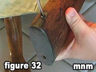
11 Page 11 of 27 30) Unscrew the lower butt plate screw. 31) Remove the lower butt plate screw. 32) Unscrew the upper butt plate screw.

 Remove the butt")
 Figure 35 shows")
12 Page 12 of 27 33) Remove the upper butt plate screw. 34) Remove the butt plate and set aside. 35) Figure 35 shows the sear pin.

 Remove the sear spring and set")

13 Page 13 of 27 36) Lightly tap out the sear pin. 37) Remove the sear pin and set aside. 38) Remove the sear spring and set both the trigger and sear spring aside. You have completed the rifle disassembly. Reassembly Instructions

 A trick to easily install the trigger assembly and")

14 Page 14 of 27 39) Place the sear spring on the sear spring pin on the sear as shown in figure ) Place trigger and sear back onto receiver. 41) A trick to easily install the trigger assembly and sear pin is to use a quick grip or other non marring clamp and clamp the trigger assembly to the receiver as shown in figure 41.

 Reinstall the")
 Return the barrel")
15 Page 15 of 27 42) Lightly tap the sear pin into the sear. 43) Reinstall the upper tang. 44) Return the barrel and receiver to the stock.

 Reinstall the")

16 Page 16 of 27 45) Figure 45 shows the receiver properly sitting on top of the upper tang. 46) Reinstall the trigger and magazine assembly. 47) Reinstall the lower tang.


17 Page 17 of 27 48) Insert the front guard screw. 49) Tighten the front guard screw. 50) Install the rear guard screw.

 Install the")
 Tighten the")
18 Page 18 of 27 51) Tighten the rear guard screw. 52) Install the tang screw. 53) Tighten the tang screw.

 Install the rear")
 Install the")
19 Page 19 of 27 54) Reinstall the rear sling swivel. 55) Install the rear swivel screw. 56) Install the front swivel screw.


20 Page 20 of 27 57) Tighten the front swivel screw. 58) Tighten the rear swivel screw. 59) Reinstall the butt plate.

 Tighten the lower")

21 Page 21 of 27 60) Reinstall the lower butt plate screw. 61) Tighten the lower butt plate screw. 62) Reinstall the upper butt plate screw.


 Slide the lower band")
22 Page 22 of 27 63) Tighten the upper butt plate screw. 64) Lift the rear sight and slide the hand guard into place. 65) Slide the lower band over the front sight.

 Figure 67 shows the direction that")

23 Page 23 of 27 66) While depressing the lower band spring slide the lower band into place. 67) Figure 67 shows the direction that the bayonet lug should point in relation to the muzzle. 68) Slide the bayonet band over the front sight.

 Insert cleaning rod.")

24 Page 24 of 27 69) Depress the bayonet band spring and slide the bayonet band into place. 70) Insert cleaning rod. 71) Reinsert the floor plate and follower into the magazine well.

 Reinstall the")

25 Page 25 of 27 72) Push down on the floor plate until is locks in place. 73) Reinstall the bolt/receiver cover back onto the bolt. 74) Figure 74 shows the left hand receiver cover groove.

 Insert the bolt and")

26 Page 26 of 27 75) Figure 75 shows the right hand receiver cover groove. 76) Insert the bolt and bolt/receiver cover into the grooves. 77) Press down on the follower and push the bolt forward.

27 Page 27 of 27 78) Figure 78 shows the reassembled rifle.
1) Place the magazine cut-off in the center position between off and on (as shown in figure 1). 2) Remove the bolt.
 Place the magazine cut-off in the center position between off and on (as shown in figure 1). 2) Remove the bolt.") 1) Place the magazine cut-off in the center position between off and on (as shown in figure 1). 2) Remove the bolt. 3) Unscrew upper band screw. 4) Remove the upper band screw. 5) Loosen the stacking swivel
1) Place the magazine cut-off in the center position between off and on (as shown in figure 1). 2) Remove the bolt. 3) Unscrew upper band screw. 4) Remove the upper band screw. 5) Loosen the stacking swivel
M14 MODULAR CHASSIS SYSTEM (MOD 1) INSTRUCTION MANUAL. West Springfield, MA Phone: (866) FAX: (413)
 INSTRUCTION MANUAL. West Springfield, MA Phone: (866) FAX: (413)") M14 MODULAR CHASSIS SYSTEM (MOD 1) INSTRUCTION MANUAL Troy Industries, Inc. WWW.TROYIND.COM West Springfield, MA 01089 Phone: (866) 788-6412 FAX: (413) 383-0339 Thank You M14/M1A MODULAR CHASSIS SYSTEM
M14 MODULAR CHASSIS SYSTEM (MOD 1) INSTRUCTION MANUAL Troy Industries, Inc. WWW.TROYIND.COM West Springfield, MA 01089 Phone: (866) 788-6412 FAX: (413) 383-0339 Thank You M14/M1A MODULAR CHASSIS SYSTEM
How to: Disassemble and Reassemble the M1 Garand.
 Yugo M-48 M1 Garand Russian Mosin Nagant Swiss Schmidt Rubin Swedish Mauser German Mauser 98k Finnish Nagant Nagant Carbines How to: Disassemble and Reassemble the M1 Garand. So, you just purchased a surplus
M*CARBO Winchester Model 70 Trigger Spring Kit Download or Print Instructions Contact: Page 1
 Download or Print Instructions Contact: help@mcarbo.com Page 1 Step 1: Clear your Firearm - Remove the magazine, check the chamber, bolt face and magazine well. Step 2: Gather Parts and Tools Needed Step
HOW TO TUNE A QB SERIES CO2 AIRGUN FOR NOOBS.
 THE UK CHINESE AIRGUN FORUM PRESENTS... HOW TO TUNE A QB SERIES CO2 AIRGUN FOR NOOBS. DISCLAIMER: THE FOLLOWING GUIDE WILL IMPROVE THE PERFORMANCE AND SMOOTHNESS OF THESE AIRGUNS, IT IS ESSENTIAL THAT
AXIOM Rifle Stock. Owner s Manual. Installation Instructions
 AXIOM Rifle Stock Owner s Manual Page 1 Installation Instructions ATTENTION: Read and follow all instructions and warnings prior to installation and/or firing a Axiom equipped firearm. Take extra time
HDL(M)6 Nut/Screw Assembly
6 Nut/Screw Assembly") HDL(M)6 Nut/Screw Assembly Remove, repair, and reassemble the nut and screw assembly in your HDL series double lock vise. In these instructions when we refer to the front of the vise or nut/screw assembly,
HDL(M)6 Nut/Screw Assembly Remove, repair, and reassemble the nut and screw assembly in your HDL series double lock vise. In these instructions when we refer to the front of the vise or nut/screw assembly,
WESTERN PISTOL.22 CALIBER SINGLE SHOT. Entire pamphlet Copyrighted by JACO Designs 1972
 WESTERN PISTOL.22 CALIBER SINGLE SHOT Entire pamphlet Copyrighted by JACO Designs 1972 This pamphlet contains the plans and instructions necessary to construct the Western pistol. This pistol breaks open
2014 Lancer Systems all rights reserved
 2014 Lancer Systems all rights reserved PROPRIETARY NOTICE: This contains Lancer Systems confidential, proprietary and/or competition sensitive data. ITAR NOTICE: Warning This document contains technical
AR15 SUPER SLIM AND ULTRA SLIM FREE FLOAT RAIL SYSTEMS
 MUM066011803 AR15 SUPER SLIM AND ULTRA SLIM FREE FLOAT RAIL SYSTEMS Proudly Designed and Made in USA Super Lightweight, Flush Fitting, and Continuous with Flat Top AR15 Upper Receiver Features Integral
QB78 CO 2 Pellet Rifle
 QB78 CO 2 Pellet Rifle Maintenance Instructions Text and photos by George Fox Lang The Chinese QB78 pellet rifle is one of the nicest and most popular CO 2 rifles ever produced. Here are the long-wanted
and ps is ready to help!
 these m14 rifles have real stopping power. I m impressed. yeah, they re good all right, but I m not sure how we re supposed to take care of the m14. ah 1961, a good year for the m14. we don t have a tm,
To install new top weight plate bushings in G7 strength units.
 1/5 PURPOSE To install new top weight plate bushings in G7 strength units. RE-WORK PARTS REQUIRED - ZMS4000424 Top Weight Plate Bushing (Quantity 4 per machine). - Matrix Top Weight Plate Bushing Removal
CHICKEN COOP & CHICKEN RUN. Tools required for assembly (not included)
") CHICKEN COOP & CHICKEN RUN ASSEMBLY MANUAL SKU# 6839 Tools required for assembly (not included) Distributed by: TRACTOR SUPPLY COMPANY 0 VIRGINIA WAY, BRENTWOOD, TN 3707 For customer support, call: -888-376-960
CHICKEN COOP & CHICKEN RUN ASSEMBLY MANUAL SKU# 6839 Tools required for assembly (not included) Distributed by: TRACTOR SUPPLY COMPANY 0 VIRGINIA WAY, BRENTWOOD, TN 3707 For customer support, call: -888-376-960
Procedures to clean your P1853 Enfield Rifled Musket
 1 Procedures to clean your P1853 Enfield Rifled Musket Regimental Quartermaster, Inc. has prepared these instructions to assist you in the care and maintenance of your P1853 Enfield black powder musket.
Replacing the Reciprocator on the SWF Compact Series Machine (601C and 1201C)
") Follow the instructions below to replace the reciprocator in the SWF Compact series machines. The tools required can be found in the tool kit that came with the machine. Preparation 1. First, place the
Follow the instructions below to replace the reciprocator in the SWF Compact series machines. The tools required can be found in the tool kit that came with the machine. Preparation 1. First, place the
Procedures to clean your M1842 Springfield Musket (Smoothbore and/or Rifled)
") 1 Procedures to clean your M1842 Springfield Musket (Smoothbore and/or Rifled) Regimental Quartermaster, Inc. has prepared these instructions to assist you in the care and maintenance of your M1842 Springfield
1 Procedures to clean your M1842 Springfield Musket (Smoothbore and/or Rifled) Regimental Quartermaster, Inc. has prepared these instructions to assist you in the care and maintenance of your M1842 Springfield
REVERSE DRAW CROSSBOW ASSEMBLY MANUAL
 REVERSE DRAW CROSSBOW ASSEMBLY MANUAL FOR ALL REVERSE DRAW CROSSBOW MODELS MANUFACTURED BY TENPOINT CROSSBOW TECHNOLOGIES HORTON CROSSBOW INNOVATIONS WICKED RIDGE CROSSBOWS TO REDUCE YOUR RISK OF SERIOUS
CALIBURN ASSEMBLY INSTRUCTIONS
 CALIBURN ASSEMBLY INSTRUCTIONS The Caliburn is a Mag-Fed Pump-Action Homemade Nerf Blaster design released as a Public Domain license file set by Captain Slug (http://www.captainslug.com). You are welcome
Ford Pick Up Rear leaf Spring Kit Installation Instructions
 1948-1956 Ford Pick Up Rear leaf Spring Kit Installation Instructions 1-800-984-6259 www.totalcostinvolved.com Parts 48 inch leaf (2) springs (4) U-bolts 3/8-24 x l 1/4bolts (16) & nuts (2) 1/2-20 x 4
Maintenance & Parts list for:
 Maintenance & Parts list for: Industrial gun GB 2 Juni 2017 This Maintenance & Parts list for industrial gun is prepared by : Winchester Europe Service V. Parbst & Søn as a comprehensive maintenance guide
OD1505 MAINTENANCE OF THE M249 MACHINEGUN
 SUBCOURSE OD1505 EDITION 7 MAINTENANCE OF THE M249 MACHINEGUN US ARMY TANK TURRET REPAIRER CORRESPONDENCE COURSE MOS/SKILL LEVEL: 45K30 MAINTENANCE OF THE M249 MACHINEGUN SUBCOURSE NO. OD1505 US Army
JARVIS. Model Brisket Scissor EQUIPMENT... TABLE OF
 Model 423-17 Brisket Scissor EQUIPMENT SELECTION... Ordering No. TABLE OF CONTENTS... Page Model 423--17... 4037003 Air Filter / Regulator / Lubricator 3022003 Air Hose Assembly... 3059018 Balancer...
CALIBURN ASSEMBLY INSTRUCTIONS
 CALIBURN ASSEMBLY INSTRUCTIONS The Caliburn is a Mag-Fed Pump-Action Homemade Nerf Blaster design released as a Public Domain license file set by Captain Slug (http://www.captainslug.com). You are welcome
Homecrest Style Sling Standard Chair Installation Instructions
 1 Homecrest Style Sling Standard Chair Installation Instructions Tools Required Sheppard Hook Spreader Tool Rubber Mallet 7/16 Ratchet/Wrench OPTIONAL NEW HARDWARE PER CHAIR Although your existing Homecrest
Remington 2014 Parts Price List
 Remington 204 Parts Price List )FFL 5)RARC )Factory Remington 204 Parts Price List F9745 V-3 AUTO SAFETY ACTUATING ROD F9735 V- AUTO SAFETY ACTUATOR F97822 V-2 AUTO SAFETY ACTUATOR PIN V- BARREL SELECTOR
REPLACEMENT TARP for SRT-2 SPOOL ROLL TARP
 REPLACEMENT TARP for SRT-2 SPOOL ROLL TARP NOTICE TO INSTALLER: Even if familiar with product, read instructions prior to installation as improvements may be made without notice. Always handle components
CALIBURN ASSEMBLY INSTRUCTIONS
 CALIBURN ASSEMBLY INSTRUCTIONS The Caliburn is a Mag-Fed Pump-Action Homemade Nerf Blaster design released as a Public Domain license file set by Captain Slug (http://www.captainslug.com). You are welcome
Practical Scrap Metal Small Arms Vol.10 By Professor Parabellum
 Practical Scrap Metal Small Arms Vol.10 By Professor Parabellum Introduction The 9mm submachine gun design described here is extremely basic and can be put together using very limited tools and materials.
ASSEMBLY INSTRUCTIONS
 ASSEMBLY INSTRUCTIONS Main illustration: Premier Combo Chair with Arm Rest deployed Arm Rest extended Rifle Stock Rest Shotgun Format Premier Combo Chair (Rifle and Shotgun Chair Combined) with Arm Rest
TOYOTA TUNDRA CARGO DIVIDER Preparation. Part Number: PT
 Preparation Part Number: PT767-34070 Kit Contents 1 1 Divider Screen 2 1 LH Bracket with Warning Label 3 1 RH Bracket without Warning Label NOTE: Part number of this accessory may not be the same as the
Ringblaster Mark IV Maintenance Guide. Version 1.5
 Ringblaster Mark IV Maintenance Guide Version 1.5 WARNING Winchester Industrial Equipment and Loads must be properly stored, handled and maintained for safe and proper function. Mishandling or failure
Hardware and Components:
 Hardware and Components: (A) 5/16 x 2 Hex Bolt (B) 5/16 x 2-1/4 Hex Bolt (C) 5/16 x 2-1/2 Hex Bolt (D) 4X 5/16 x 3/4 Hex Bolt (E) 4X 5/16 x 1-1/4 Hex Bolt (F) 11X 5/16 Flat Washer (G) 12X 5/16 Nylock Nut
Introduction. Rocky Mountain Westy Swing Away Carrier Kit Installation Instructions
 Rocky Mountain Westy Swing Away Carrier Kit Installation Instructions Introduction Thank you for purchasing the Rocky Mountain Westy Swing Away Carrier Kit. We pride ourselves in the products we develop
1) Place the reactor stand on a sturdy bench with the bottom plate facing toward the front.
 Place the reactor stand on a sturdy bench with the bottom plate facing toward the front.") Assembly Instructions for ChemRxnHub Reactor Systems 1) Place the reactor stand on a sturdy bench with the bottom plate facing toward the front. Loosen knobs on the right and left using 2 hands of the
Assembly Instructions for ChemRxnHub Reactor Systems 1) Place the reactor stand on a sturdy bench with the bottom plate facing toward the front. Loosen knobs on the right and left using 2 hands of the
RIVAL CALIBURN ASSEMBLY
 RIVAL CALIBURN ASSEMBLY 08/02/18 The RIVAL Caliburn is a Mag-Fed Pump-Action Homemade Nerf Blaster design released as a Public Domain license file set by Captain Slug (http://www.captainslug.com). You
Exponents Bench Cushion
 Exponents Bench Cushion Power Drill #2 Phillips Bit Bit Holder Page 1 of 2 939500640 Rev A 1. Place cushion on top of the bench, so the black Coalesse tag is in the right rear corner of the bench. 2. From
CALIBURN ASSEMBLY INSTRUCTIONS
 CALIBURN ASSEMBLY INSTRUCTIONS The Caliburn is a Mag-Fed Pump-Action Homemade Nerf Blaster design released as a Public Domain license file set by Captain Slug (http://www.captainslug.com). You are welcome
Replacing the build plate clamps
 Repair manual Replacing the build plate clamps Instructions The build plate clamps hold the glass plate in place on the heated bed. There are two fixed in place at the back of the heated bed and two at
Rugged Ridge Engine Transmission Skid Plate JK
 Installation Time: 1-2 Hours Tools Required: Rugged Ridge Engine Transmission Skid Plate 2012-2017 JK Sockets: 16mm, 17mm, 18mm deep well Socket Wrench Wrenches: 16mm, 18mm Torque Wrench Drill ½ Drill
Replacing the build plate clamps
 Repair manual Replacing the build plate clamps Instructions The build plate clamps hold the glass plate in place on the heated bed. There are two fixed in place at the back of the heated bed and two at
MULTI-ACTIVITY PLAY TABLE
 ASSEMBLY INSTRUCTIONS! WARNING: CHOKING HAZARD - Small parts. Not for children under 3 years.! CAUTION: Adult assembly required. C 2006 Melissa and Doug, Inc. All Rights Reserved www.melissaanddoug.com
Model 209 Fireback Replacement
 Model 209 Fireback Replacement Please read all the instructions before you begin the procedure. Confirm that you have all the necessary tools and materials. If you have any questions, technical support
`48-`56 Ford Pickup Rear leaf Spring Kit Installation Instructions Tech Line:
 `48-`56 Ford Pickup Rear leaf Spring Kit Installation Instructions Tech Line: 1-855-693-1259 www.totalcostinvolved.com CHECK ALL PARTS INCLUDED IN THIS KIT TO THE PARTS LIST BEFORE INSTALLING THE KIT.
Maintenance Information
 16601023 Edition 2 January 2014 Air Impact Wrench 2705P1 Maintenance Information Save These Instructions Product Safety Information WARNING Failure to observe the following warnings, and to avoid these
F-150 Structural Holding System
 F-150 Structural Holding System Users Manual December 2013 by Vehicle Service Group. All rights reserved. CO8812.2 502073 Rev. - 12/11/2013 CHIEF'S LIMITED ONE-YEAR WARRANTY & LIABILITY Chief Automotive
RACER TECH COMMANDER HD TIE ROD INSTALLATION
 RACER TECH COMMANDER HD TIE ROD INSTALLATION NOTE: These instructions are a universal explanation of how to install our HD Tie Rods. All kits are identical for all inner joints and nearly identical for
mila-wall (Series100) General Operating Instructions page 1 of 15
 General Operating Instructions page 1 of 15") mila-wall (Series100) General Operating Instructions page 1 of 15 Step #1: Before setting up walls, lower adjustable leveling feet on each panel approximately 1". This will allow access to the threaded
mila-wall (Series100) General Operating Instructions page 1 of 15 Step #1: Before setting up walls, lower adjustable leveling feet on each panel approximately 1". This will allow access to the threaded
Midwest RDH Handpiece Repair Procedure
 Midwest RDH Handpiece Repair Procedure The Midwest RDH handpiece is fairly common and is used by hygienists to clean teeth. The most common problems for this handpiece include a bad prophy head or a dirty
Arc Trainer Main Frame Assembly
 Arc Trainer Main Frame Assembly Kit No. 610AK019-4 Kit No. 630AK019-4 NOTE: This instruction sheet describes how to replace the main frame assembly in the Arc Trainer 610A. Tools Required 3/16 Allen wrench
Installation Guide for Rough Country 1.25 inch Body Lift Kit w/o Shocks (07-15 Wrangler JK 4 Door) Item # J10048 Option B; Manual
 Item # J10048 Option B; Manual") Installation Guide for Rough Country 1.25 inch Body Lift Kit w/o Shocks (07-15 Wrangler JK 4 Door) Item # J10048 Option B; Manual Installation Time: 3 Hours Tools Required: Jack (Tall enough to reach body
Installation Guide for Rough Country 1.25 inch Body Lift Kit w/o Shocks (07-15 Wrangler JK 4 Door) Item # J10048 Option B; Manual Installation Time: 3 Hours Tools Required: Jack (Tall enough to reach body
INSTRUCTIONS FOR ARMOURERS PART II SMALL ARMS
 INSTRUCTIONS FOR ARMOURERS PART II SMALL ARMS CHAPTER I RIFLES Drawing Nos. S.A.I.D. 2058; 2059; 2267; 2268; 2269. Section 1. Stripping and Re-assembling 1. To strip Rifles No. 1, Mk. III & III*, and Rifles
CALIBURN ASSEMBLY INSTRUCTIONS
 CALIBURN ASSEMBLY INSTRUCTIONS The Caliburn is a Mag-Fed Pump-Action Homemade Nerf Blaster design released as a Public Domain license file set by Captain Slug (http://www.captainslug.com). You are welcome
WILLIS WALL-MOUNT FAUCET INSTALLATION
 SKU(s): 924620 BEFORE YOU BEGIN We recommend consulting a professional if you are unfamiliar with installing bathroom fixtures and plumbing. Signature Hardware accepts no liability for any damage to the
ASSEMBLY INSTRUCTIONS DIY WALL BED KIT QUEEN BI FOLD DOOR CABINET & MECHANISM. Tools Required For Assembly. 6.5mm Masonry Drill Bit
 ASSEMBLY INSTRUCTIONS DIY WALL BED KIT QUEEN BI FOLD DOOR CABINET & MECHANISM Tools Required For Assembly No 2 & No 4 Phillips Head Screwdrivers No 2 Slot Head Screwdriver Hammer Electric Drill (Hammer
DYNATRAC BALL JOINT REBUILD INSTRUCTIONS V4.0
 DYNATRAC PRODUCTS 2007-2016 4X4 JEEP JK HEAVY DUTY BALL JOINT JP44-2X3050-C DYNATRAC BALL JOINT REBUILD INSTRUCTIONS V4.0 WARNING: Improper use or installation of this product can cause major failures
STOP. V00029AC Rev. 04 READ ALL OF THE FOLLOWING INSTRUCTIONS BEFORE REMOVING CABINET FROM SKID TOOL LIST. NET-ACCESS S-Type Network Cabinets
 Rev. 04 STOP READ ALL OF THE FOLLOWING INSTRUCTIONS BEFORE REMOVING CABINET FROM SKID NET-ACCESS S-Type Network Cabinets -Phillips screwdriver -Flatblade screwdriver -22mm socket wrench -15mm socket wrench
TASK: Replace Control Mechanism/Drive End for G71 Supervue/Everglide Vertical headrail
 1. Locate the clear plastic louver stems where louvers are attached. 2. Rotate louvers open. Slide a hard plastic card between the louver and the long side of the louver stem. Push the card and louver
PROSTEER BALL JOINT REBUILD INSTRUCTIONS V1.0
 DYNATRAC PRODUCTS 2003-2010 4X4 DODGE 2500/3500 HEAVY DUTY BALL JOINT PROSTEER BALL JOINT REBUILD INSTRUCTIONS V1.0 WARNING: Improper use or installation of this product can cause major failures that could
CALIBURN ASSEMBLY INSTRUCTIONS
 CALIBURN ASSEMBLY INSTRUCTIONS The Caliburn is a Mag-Fed Pump-Action Homemade Nerf Blaster design released as a Public Domain license file set by Captain Slug (http://www.captainslug.com). You are welcome
Removing and Replacing the Y-truck
 Service Documentation Removing and Replacing the Y-truck To remove and replace the Y-truck you will need the following tools: 4mm Allen wrench 12mm stamped flat wrench #2 Phillips screwdriver (magnetic
SCHACHT STANDARD FLOOR LOOMTM
 SCHACHT STANDARD FLOOR LOOMTM FL3109 FL3111 FL3113 FL3115 FL3121 FL3123 FL3125 FL3127 FL3310 FL3312 FL3314 FL3316 FL3322 FL3324 FL3326 FL3328 Assembly instructions LOW CASTLE LOOM IN MAPLE Find out more
CARBINE BOLT ASSEMBLY AND DISASSEMBLY WITHOUT THE BOLT TOOL
 March 2016, page 1 of 7 CARBINE BOLT ASSEMBLY AND DISASSEMBLY WITHOUT THE BOLT TOOL The below article was scanned from the Army magazine, The Ordnance Sergeant, dated March 1945. Thanks to John Spangler
Revised
 Indentify Non-powered panels and separate from Powered panels. Non-powered panel shown at left.. Powered panel shown at left has powerway mounted at factory. Also separate panels by surface type, width
Rev B C-RING TOOL VA0375 ½ in. OPERATING MANUAL
 Rev B 4-30-0 C-RING TOOL VA0375 ½ in. OPERATING MANUAL Operational Instructions for Vertex C-Ring Tool VA0375 Vertex Fasteners is committed to providing our customers with world-class customer service
Footprint Mobile Assembly Instructions
 Footprint Mobile Assembly Instructions 1998754 Revision -1 Complete Series Master Packet If you have any questions concerning these instructions, please call Kimball Office Customer Service. 20 Kimball
1. Turn off or disconnect power to unit (machine). 2. Push IN the release bar on the quick change base plate. Locking latch will pivot downward.
. 2. Push IN the release bar on the quick change base plate. Locking latch will pivot downward.") Figure 1 Miniature Quick Change Applicators, of the end feed type, are designed to crimp end feed strip terminals to prestripped wires. Each applicator is set up to accept the strip form of certain specific
Figure 1 Miniature Quick Change Applicators, of the end feed type, are designed to crimp end feed strip terminals to prestripped wires. Each applicator is set up to accept the strip form of certain specific
Strata. urniture. Adriana Instructions. Parts in the Arm Box: Parts in the Body Box: Watch our assembly videos at
 1A Watch our assembly videos at www.strataf.com/videos Parts in the Arm Box: Arm - Outside View Arm - Inside View 1B Parts in the Body Box: Back Deck x 1 Seat Deck x 1 with the Feet attached Back Panel
Astro-Physics Inc. 400QMD Lubrication/Maintenance Guide
 Astro-Physics Inc. 400QMD Lubrication/Maintenance Guide The following guidelines should be followed to lubricate the three main parts of the 400QMD mount. The QMD stands for Quartz Micro-Drive controller.
INSTALLING YOUR NEW SPRING LIFT ARM KIT
 INSTALLING YOUR NEW SPRING LIFT ARM KIT 1. Measure the distance that the roof is to be raised. [If your lift system is completely non-functional, you will need to calculate or estimate this distance as
Now you are only cutting a groove in the lower half of the receiver, if your 46
 The picture on the left shows the shape of the cutter that I ground. The picture on the right shows a picture of a cut off tool replaceable cutting bit that I used as a pattern to grind my own cutter.
ROSS RIFLE HANDBOOK OTI'AWA. GovERNMENT PRINTING BuREAU
 ROSS RIFLE HANDBOOK 1907 OTI'AWA GovERNMENT PRINTING BuREAU 2686 1907 2686-lt 3 ROSS RIFLE HANDBOOK CONTENTS THE MARK I. RIFLE. P.~GE. Names of the parts of Ross Rifle, Mark I..............................
White Quail Auto Trap
 White Quail Auto Trap WARNING SAFETY, STORAGE & USE IF THE MAIN SPRING IS ATTACHED AND THE TRAP ARM IS IN THE 6 O CLOCK POSITION, THE TRAP IS ARMED AND EXTREME CAUTION IS REQUIRED. TO DISARM, TURN THE
BIFOLD FUTON FRAME TRINITY ARM. Seat Rails and Slats x 1. *Note: Use 4pc of 100mm Bolts and 4pc of 60mm Bolts to attach the arms to the Stretchers.
 1A Parts in this box. 2pc with extra holes 2pc with extra holes & plastic stoppers Arms x 2 Back Rails and Slats x 1 Full Size: Slat Supports x 6 3pc are longer for the Back deck Back Side Rails x 2 Seat
DYNATRAC BALL JOINT REBUILD INSTRUCTIONS V5.0
 DYNATRAC PRODUCTS 2007-2018 JEEP JK HEAVY DUTY BALL JOINT JP44-2X3050-C DYNATRAC BALL JOINT REBUILD INSTRUCTIONS V5.0 WARNING: Improper use or installation of this product can cause major failures that
Two Piece Chaise Install Process
 Two Piece Chaise Install Process Carefully cut the original sling material to be replaced down the middle with scissors or a box cutter. Before beginning be sure to have the following items at hand: Chair
VB36 SHORTBED.TAILSTOCK
 VB36 SHORTBED.TAILSTOCK (Principal Components) PART REF. SBT 1 SBT2 SBT3 SBT4 SBT5 SBT6 SBT7 SBT8 SBT9 DESCRIPTION Tailstock Body Casting Taper Block Handle Bracket Han41eLink Handle Bed Tube Tailstock
Bend-Tech Dragon Assembly Manual
 p.1 Bend-Tech Dragon Assembly Manual IMPORTANT: Please read before unpacking. Place shipping container in a wide open area where you will have room to work and assemble this product. Shipping The Dragon
KWM Gutterman Inc. 5 /6 IRONMAN COMBO CONVERSION
 5 /6 IRONMAN COMBO CONVERSION SECTION: 2 6 To 5 Conversion This section will direct you in converting your combo machine from a 6 to 5 machine. BEFORE BEGINNING CHANGEOVER Eliminate electrical power source
LAN84207 Installation Instructions Single Point Hydraulic Kit for 50 Series STS Combines. 270 West Park Avenue Huron, SD
 LAN84207 Installation Instructions Single Point Hydraulic Kit for 50 Series STS Combines. 270 West Park Avenue Huron, SD 57350 866-526-5682 1 Numerical Parts List Part Numbers Description Quantity LANH201368
Hardware and Components:
 Hardware and Components: (A) 4X 5/16 x 1 Carriage Bolt (B) 2X 5/16 x 2-1/4 Carriage Bolt (C) 2X 5/16 x 3-1/4 Hex Bolt (D) 2X 5/16 x 3/4 Hex Bolt (E) 2X 5/16 x 1-1/4 Hex Bolt (F) 5/16 x 2-1/4 Hex Bolt (G)
Hammerli SP20. Hammerli SP20. Rear Sight Adjustments. (1 of 7) :22:02
 :22:02") Hammerli SP20 Rear Sight Adjustments http://www.pilkguns.com/tenp/sphsp20.htm (1 of 7)30.05.2005 14:22:02 Clockwise down (screw 69). 1 click = 100 @ 25m. Clockwise left (screw 64). 1 click = 8mm @ 25m.
Hammerli SP20 Rear Sight Adjustments http://www.pilkguns.com/tenp/sphsp20.htm (1 of 7)30.05.2005 14:22:02 Clockwise down (screw 69). 1 click = 100 @ 25m. Clockwise left (screw 64). 1 click = 8mm @ 25m.
FACTORY CAT TOMCAT CORPORATION
 FACTORY CAT RPS TOMCAT CORPORATION Artificial Turf and Carpet Sweeping Install Kit #349-641 & #349-642 1. Detach batteries so that there is no power running through the machine before starting. 2. Start
AUTO STABILIZING AND LEVELLING SYSTEM
 Installation Manual Make sure the caravan is parked in a safe place. Make sure the caravan brake is on. Remove all 4 corner steady legs from the caravan. Remove the corner steady legs by removing the 3
3/2004. Core Barrel Tool Assembly and Disassembly
 3/2004 Core Barrel Tool Assembly and Disassembly Core Barrel Tool Assembly and Disassembly This document covers the assembly and disassembly procedure for two variants of the Core Barrel modular system:
Clearview Railing System Installation Instructions
 Clearview Railing System Installation Instructions Disclaimer: AGS Stainless, Inc. has its Clearview Railing Systems designed by a professional engineer to meet the requirements of the latest national
LASER ENHANCED REVOLVER GRIP OWNER S MANUAL RED LASER GREEN LASER
 LASER ENHANCED RED LASER GREEN LASER REVOLVER GRIP OWNER S MANUAL LASER ENHANCED GRIP Installation Instructions Caution... 3 Safety Labels... 4 Installation...5-7 Programming...8-10 Batteries (Red Laser)...
Replacing the Reciprocator on an SWF Multi-head.
 Replacing the Reciprocator on an SWF Multi-head. Follow the instructions below to replace the reciprocator in the SWF multi-head machines. The tools required are found in the tool kit that came with the
Door window. Front door window, assembly overview
 64-50 Door window Front door window, assembly overview 1 - Window channel Pushed onto flange 2 - Door window Removing Page 64-52 Adjusting Page 64-53 3 - Door 4 - Outer window channel Pushed onto flange
AR-15 Armorer s Essentials Kit. Product # Instructions # Revision: B
 AR-15 Armorer s Essentials Kit Product #156111 Instructions #1025769 Revision: B 1 INDEX 3 AR-15 Adjustable Receiver Link 3 Pivot Pin and Roll Pin Installation Tool 4 Mag well Vise Block 7 Upper Vise Block
Special Z-Axis Ballscrew Replacement
 To replace Z-axis ballscrew without removing X-axis components When rebuilding an OmniTurn slide, all the precision components are replaced. The tooling plate and saddle are removed to gain access to the
08+ KAWASAKI KLR PD NERF
 08+ KAWASAKI KLR PD NERF 0505-1299 Before you begin, place the bike on a hard level surface where you have room to work. Lay out the parts included in this kit and compare to the parts list on page 5 of
Regulator installation guide Air Arms S4xx/S5xx
 Welcome to Huma-Air. We design and manufacture brand- and model specific precision regulators for PCP air rifles. By using only the highest quality materials such as aircraft grade aluminum, aluminumbronze,
KIT. Assembly Instructions. HayDay, LLC
 KIT Assembly Instructions HayDay, LLC 1-800-732-1654 www.stablegrazer.com Read completely through the assembly instructions before starting assembly. The Stable Grazer Kit comes in two boxes. Remove all
INSTALLATION INSTRUCTIONS FOR HAND OPERATED MODELS: 170, 171-R, 171-N, 172, 260
 INSTALLATION INSTRUCTIONS FOR HAND OPERATED MODELS: 170, 171-R, 171-N, 172, 260 I. SUSPENDED INSTALLATIONS NOTE: MODEL 260 FENSTEEL TRACK IS ASSEMBLED IN THE SAME MANNER AS DESCRIBED BELOW WITH THE EXCEPTION
OPERATIONAL MANUAL V1.0. Removing/Replacing Blades
 OPERATIONAL MANUAL V1.0 BLUEROCK WS-212 Wire Stripper Removing/Replacing Blades CAUTION!! IMPORTANT!! DANGER!! WARNING!! DISCONNECT MACHINE FROM POWER BEFORE PROCEEDING!! Estimated Completion Time: 90
STRAIGHT HANDLEBAR KIT
 STRAIGHT HANDLEBAR KIT P/N 2881973 APPLICATION All straight bar applications, excluding 550 Indy and Voyageur models BEFORE YOU BEGIN Read these instructions and check to be sure all parts and tools are
a.k.a. casegoods instructions
 a.k.a. casegoods instructions a a.k.a. workwall installation IMPORTANT NOTES Failure to install product according to installation instruction will result in loss of warranty. Tools required for assembly