Daytime Running Lights - Splice-in (10-12 All):
|
|
|
- Nickolas Matthews
- 6 years ago
- Views:
Transcription

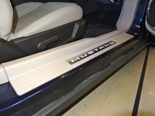
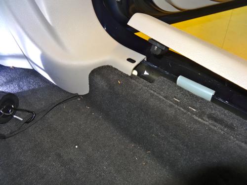
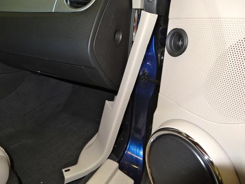
1 Time Necessary: Approximately 1 hour Tools Required: Heat Gun Installation Procedure: Daytime Running Lights - Splice-in (10-12 All): 1. It is recommended that the positive terminal be removed from the battery prior to any electrical installation. A good tip to follow once the terminal is loosened and removed, is to place a workshop rag over the battery. Battery cables have a tendency to creep back to their original location and this will prevent any surprises while you are under the dash. 2. Remove the fuse panel cover at the back of the passenger kick panel. Four clips on the carpet side and doublesided tape on the exterior body side hold the sill plate in place and there is no need to remove the entire sill plate. The tape is very adhesive and there is a tendency to bend the metal Mustang nameplate if you try to remove the entire sill. Pull up on the carpet side at the front of the sill along with the front adhesive tape. Your goal here is to allow the passenger kick plate to be removed from under the sill plate without pulling the entire sill plate off. Next pull back on the kick plate, as there are a number of clips holding it on.
2
 covering the connectors and fuse box.")

 Connector C2280D Connector")

3 3. Now that the Smart Junction Box area is exposed lift up on the thin black plastic sheet (A) covering the connectors and fuse box. The second black plastic sheet (B) is held in place by white tape. Peel this off the junction box and keep it on the plastic sheet for later reassembly. Plastic Sheet - A Plastic Sheet B (c/w tape) Connector C2280D Connector C2280F 4. If you elect to use the synchronizing wire as described in the instructions you will need to prepare the module, which is easier done outside of the car. Cut the white wire in half and use the quick splice connector to attach it to the green wire.


4 5. Snap and slide the white clip on top of connector C2280F to the left to release the connector from the junction box. Carefully cut the black wrap tape from the wire harness and locate the blue/green and yellow/violet wires. Cut the two wires half way up the wiring harness and strip the ends. The DRL kit is supplied with white Marrett or Wire-nut joiners, which at this point you can use to join the wires. If you have access to a soldering iron and heat shrink tubing this would be the best method to connect the wires in all electrical projects. 6. Slide a 1.5 length of 3/16 heat tubing over the red wire from the DRL module. Twist the blue/green wire from the connector to the red wire. Solder and then fold over one of the wires. Slide the heat shrink tubing over the solder joint and warm with a heat gun.


5 7. Slide a 1.5 length of 3/16 heat tubing over the pink wire from the DRL module. Twist the yellow/violet wire from the connector to the red wire. Solder and then fold over one of the wires. Slide the heat shrink tubing over the solder joint and warm with a heat gun. 8. Slide a 1.5 length of 3/16 heat tubing over the violet wire from the DRL module. Twist the yellow/violet wire from the wiring harness to the red wire. Solder and then fold over one of the wires. Slide the heat shrink tubing over the solder joint and warm with a heat gun. 9. Slide a 1.5 length of 3/16 heat tubing over the brown wire from the DRL module. Twist the blue/green wire from the wiring harness to the brown wire. Solder and then fold over one of the wires. Slide the heat shrink tubing over the solder joint and warm with a heat gun. 10. Pull down on the white tab to remove connector C2280D from the junction box. Carefully cut the black wrap tape from the wire harness and locate the yellow/gray, the violet/white and the black/white wires. You may wish to insert a small screwdriver into the backside of the connector to unclip the connector cover. This will allow you to separate all the wires and verify the correct wires and pins inside the connector since a few of them look quite similar.
6 11. Using the quick splice connectors supplied, connect the blue wire to the violet/white wire of the harness. 12. Using the quick splice connectors supplied, connect the yellow wire to the yellow/gray wire of the harness. 13. Using the quick splice connectors supplied, connect the green wire to the black/white wire of the harness. Use the supplied wire ties to secure the module to a convenient fix point along with using a wire tie to tidy up any loose wires. This guide is to be used in conjunction with the instructions provided by the manufacturer and or vendor. Installation Instructions written by AmericanMuscle customer David Orlando
GEN II Toyota Prius Back Door Opener Switch Replacement & License Plate Lights
 GEN II Toyota Prius Back Door Opener Switch Replacement & License Plate Lights Rubber Surface of Switch had Degraded to Tar-like Substance Vehicle Manufacture Date 10/06 OLD SWITCH IN GARNISH SWITCH REMOVED
PSU for LawMate 500mW Transmitters. Assembly and Operation Manual
 PSU for LawMate 500mW Transmitters Assembly and Operation Manual Introduction Thank you for purchasing LawMate 500mW Power Supply. This power supply was specifically designed for the 500mW LawMate transmitter
05-17 Mustang Fuel System Wire Upgrade Installation
 PARTS LIST: -10AWG INLINE FUSE HOLDER WITH 30AMP BLADE FUSE -16FT 10AWG HIGH CURRENT PRIMARY WIRE -40AMP AUTOMOTIVE RELAY -1FT 10AWG GROUND WIRE -1FT 10AWG HIGH CURRENT PRIMARY WIRE OUTPUT TO FPDM -1FT
Mustang Door Sill Plates Installation Guide
 Mustang Door Sill Plates Installation Guide The below installation instructions work for the following products: 1994-2004 Ford Mustang Steeda Polished Door Sill Plates Congratulations on purchasing a
Team Xecuter Joycon Mod By: XxWiReDxX
 Team Xecuter Joycon Mod By: XxWiReDxX Works With Every Switch SX OS Works with every Nintendo Switch and every firmware version! Play Every Game With SX OS you can play all your favorite games straight
PSU V2 for LawMate 500mW Transmitters. Assembly and Operation Manual
 PSU V2 for LawMate 500mW Transmitters Assembly and Operation Manual Introduction Thank you for purchasing the V2 LawMate 500mW Power Supply. This power supply was specifically designed for the 500mW LawMate
Signal Mirror Installation Instructions Honda Odyssey
 Signal Mirror Installation Instructions 2005-2009 Honda Odyssey THE safety accessory of the 21st Century. P/N 210-0122-0 Rev. A4 (6/9/09), BTV 2006 Muth Company, LLC PROFESSIONAL INSTALLATION RECOMMENDED
Conflicts Note: Drop-in Bed liner
 Toyota Tundra 2015 LED Bed Lights Preparation Part Number: 00016-34089 Accessory Code: BU1000 Conflicts Note: Drop-in Bed liner Kit Contents Item # Quantity Reqd. Description 1 1 Hardware Kit 2 1 Driver
TOYOTA TACOMA LED BED LIGHTS Preparation
 Preparation Part Number: PT948-35160 Kit Contents Item # Quantity Reqd. Description 1 1 Hardware Kit 2 1 Driver Side LED assembly 3 1 Passenger Side LED assembly 4 1 Main Wire Harness Hardware Bag Contents
MM Strut Tower Brace, Cobra (MMSTB-7)
") The MM strut Tower Brace attaches to each strut tower and to the firewall. 3430 Sacramento Dr., Unit D San Luis Obispo, CA 93401 Telephone: 805/544-8748 Fax: 805/544-8645 www.maximummotorsports.com MM
The MM strut Tower Brace attaches to each strut tower and to the firewall. 3430 Sacramento Dr., Unit D San Luis Obispo, CA 93401 Telephone: 805/544-8748 Fax: 805/544-8645 www.maximummotorsports.com MM
LED Cup Holder Lights Installation Guide
 LED Cup Holder Lights Installation Guide (20112015 Kia Optima) Thanks for purchasing this LED Cup Holder Light Kit! If you have any questions or feedback please email us direct at Sales@K5OptimaStore.com
Bi-Color Signal Mirror Installation Instructions
 Bi-Color Signal Mirror Installation Instructions 2005-2009 Toyota Tacoma THE safety accessory of the 21 st Century. P/N 210-0141-0 Rev. A2 (3/30/09), BTV 2007 Muth Mirror Systems, LLC Page 3 of 13PplPage
ROVs in a Bucket Building an Underwater Robot. 5.0 Building the Tether
 5.0 A professional ROV is connected to the controller box by strands of wire. The bundle of wires are encased in a single sheath. The connecting wire is called the tether. In our project the tether is
Instructions for Lighting an S Scale Caboose
 Instructions for Lighting an S Scale Caboose The S Scale Caboose lighting kit is adaptable for most caboose models of rolling stock including American Flyer (TM) and contains the same components as found
Splice-In Sequential Tail Lights Installation Guide (96-04)
") Splice-In Sequential Tail Lights Installation Guide (96-04) The below installation instructions work for the following products: Mustang Sequential Taillights Kit - Splice-in (96-04) Please read through
Splice-In Sequential Tail Lights Installation Guide (96-04) The below installation instructions work for the following products: Mustang Sequential Taillights Kit - Splice-in (96-04) Please read through
Signal Mirror Installation Instructions
 Signal Mirror Installation Instructions 2005-2010 Chevy Corvette C6 THE safety accessory of the 21 st Century. P/N 210-0144-0 Rev. A3 (9/29/2011), BTV 2007 Muth Mirror Systems, LLC Page 3 of 10PplPage
irobot Roomba 980 Motherboard Replacement
 You will be able to remove the device's motherboard and replace it in case it is damaged. Written By: Ernesto Rodriguez Romero ifixit CC BY-NC-SA www.ifixit.com Page 1 of 13 INTRODUCTION Replacing the
INSTALLATION INSTRUCTIONS
 3b Fig. A Fig. C Fig. B Fig. D KIT FEATURES ISO and DIN unit provisions Pocket (holds jewel cases) KIT COMPONENTS Radio Housing 99-7898 INSTALLATION INSTRUCTIONS APPLICATIONS ACCORD 990-97, CIVIC 999-00,
Cover Page. Factory Radio Other Documents Available For This Vehicle:
 Factory Radio Other Documents Available For This Vehicle: No documents available at this time Adobe Acrobat Reader Printing Tips: 1) Select FLE then PRNT and select your printer. 2) n the print options
QUALITY MANAGEMENT SYSTEM
 Not controlled in hard copy Rev. 1.0 Date: Page 1 of 18 Subject The following instructions provide a step-by-step procedure to replace the heating element for DEF/SCR/UREA/ADBLUE/DIESEL After Treatment
Installation instructions, accessories. TV receiver, digital
 Installation instructions, accessories Instruction No 30756561 Version 1.1 5 Part. No. 30756181, 30756569 TV receiver, digital Volvo Car Corporation TV receiver, digital- 30756561 - V1.1 Page 1 / 36 Equipment
Ram Truck /2500/3500
 Publication, Duplication, or Retransmission Of This Document Not Expressly Authorized n Writing By The nstall Doctor s Prohibited. Protected By U.S. Copyright Laws.,1998,1999,2000. Factory Radio Other
Pacific Antenna 20 and 40M Lightweight Dipole Kit
 Pacific Antenna 20 and 40M Lightweight Dipole Kit Antenna diagram showing configuration and lengths when assembled 7 8 16 9 16 9 Description The Pacific Antenna lightweight dual band dipole kit provides
Asus ZenFone 2 Display Replacement
 Asus ZenFone 2 Display Replacement Replace your display if it isn't functioning correctly or if it is cracked or broken. Written By: Jessica Nguyen ifixit CC BY-NC-SA www.ifixit.com Page 1 of 14 INTRODUCTION
Signal Mirror Installation Instructions Toyota Tacoma
 Signal Mirror Installation Instructions 2005-2015 Toyota Tacoma THE safety accessory of the 21 st Century. P/N 210-0115-0 Rev. A4 (3/11/15), BTV 2005 Muth Mirror Systems, LLC Page 3 of 12PplPage 3 of 12
The Useless Machine. Parts Only - Build Guide v0001
 TM The Useless Machine Parts Only - Build Guide v0001 For the best outcome, follow each step in order. We recommend reading this guide entirely before you get started. Tools required: One phillips screwdriver,
626 - Mazda MX-6 - Mazda
 Factory Radio Other Documents Available For This Vehicle: No additional documents available at this time Adobe Acrobat Reader Printing Tips: 1) Select FLE then PRNT and select your printer. 2) n the print
No crimping is required just solder the the wire to the crimp piece and use some heat shrink tubing to cover the end of the crimp.
 In this section we will be wiring up the IEC socket (AC plug) with the rocker switch and the Mains transformer primaries. Follow these instructions if you live in an area with 100, 110, 220 or 230 Volts!"
V Ford Mustang
 V8 2011 Ford Mustang N2MB WOT Box Installation Instructions NOTE: If you have a CDI (capacitive discharge ignition system) please contact us at support@n2mb.com for additional instructions. Damage to your
TOYOTA TACOMA TRAILER WIRE HARNESS Preparation
 Preparation Part Number: PT725-35120 Kit Contents Item Quantity Reqd. Description # 1 1 Flasher Assembly (F/A) 2 1 Wire Harness 3 1 Sub Wire Harness 4 2 Plastic Tie (300mm) 5 4 Plastic Tie (200mm) 6 13
Signal Mirror Installation Instructions
 Signal Mirror Installation Instructions Honda CRV 1997-2003 THE safety accessory of the 21 st Century. P/N 210-0032-0 Rev B2 (6-26-04), GG 2003 Muth Mirror Systems, LLC. Note: Professional Installation
Neon Dodge/Chrysler/Plymouth Radio Replacement Document #:
 & nstall Publication, Duplication, or Retransmission Of This Document Not Expressly Authorized n Writing By The nstall Doctor s Prohibited. Protected By U.S. Copyright Laws. 1997,1998,1999,2000. Factory
Assembly Instructions
 Unite Panel System Hinge Door July 2016 #12 x / slotted hex washer head bolt Figure 1 threshold bracket frame Detail F threshold bracket threshold bracket (installed) #12 x / slotted hex washer head bolt
I Click on a link tab to jump to that page. Cover Page
 Publication, Duplication, or Retransmission Of This Document Not Expressly Authorized n Writing By The nstall Doctor s Prohibited. Protected By U.S. Copyright Laws. 1997,1998,1999,2000. & nstall Factory
3DR ArduCopter Quad-C
 3DR ArduCopter Quad-C 3DR ArduCopter Quad-C Thank you for purchasing a 3DR ArduCopter Quad kit. The 3DR ArduCopter Quad is a stable and supported multi-rotor frame in the ongoing development of the ArduCopter
Pacific Antenna 20 and 40M Lightweight Dipole Kit
 Pacific Antenna 20 and 40M Lightweight Dipole Kit Diagram showing configuration and approximate lengths 8 6 16 9 16 9 8 6 Description The Pacific Antenna lightweight dual band, trap dipole kit provides
Signal Mirror Installation Instructions
 Signal Mirror Installation Instructions 2006 2007 Honda Ridgeline THE safety accessory of the 21 st Century. P/N 210 0142 0 Rev. A (9/5/07), BTV 2007 Muth Company, LLC Professional Installation Recommended:
IMPORTANT! Recommended Tools. 7/16 Deep socket Phillips screwdriver
 IMPORTANT! Read all instructions carefully before commencing any work. Always wear proper safety equipment. Some installation steps will require two or more installers. Recommended Tools Ratchet 10-mm
MM Strut Tower Brace, GT (MMSTB-5.1)
") 3430 Sacramento Dr., Unit D San Luis Obispo, CA 93401 Telephone: 805/544-8748 Fax: 805/544-8645 www.maximummotorsports.com MM Strut Tower Brace, 1996-97 GT (MMSTB-5.1) MMSTB-5.1 is for 1996-97 GT s with
3430 Sacramento Dr., Unit D San Luis Obispo, CA 93401 Telephone: 805/544-8748 Fax: 805/544-8645 www.maximummotorsports.com MM Strut Tower Brace, 1996-97 GT (MMSTB-5.1) MMSTB-5.1 is for 1996-97 GT s with
MacBook Pro 15" Unibody 2.53 GHz Mid 2009 Front Display Glass Replacement
 MacBook Pro 15" Unibody 2.53 GHz Mid 2009 Front Display Glass Replacement Replacing the front display glass. Written By: Andrew Bookholt ifixit CC BY-NC-SA www.ifixit.com Page 1 of 25 INTRODUCTION Use
INSTALLATION INSTRUCTIONS FOR PART TOOLS REQUIRED: Small Flat Blade Screwdriver/ Panel Removal Tool Phillips Screwdriver Socket Set
 INSTLLTION INSTRUCTIONS FOR PRT 99-65 PPLICTIONS Chrysler Sebring 007 Chrysler Town and Country 008 Dodge venger 007-008 Dodge Dakota 008 Dodge Grand Caravan 008 Dodge Nitro 007 Jeep Wrangler 007 (Modifications
Taurus - Ford Sable - Mercury
 & nstall Publication, Duplication, or Retransmission Of This Document Not Expressly Authorized n Writing By The nstall Doctor s Prohibited. Protected By U.S. Copyright Laws. 1997,1998,1999,2000. Factory
INSTALLATION INSTRUCTIONS FOR PART APPLICATIONS Toyota Matrix Pontiac Vibe
 INSTLLTION INSTRUCTIONS FOR PRT 99-8205 KIT FETURES DIN head unit provision ISO DIN head unit provision DDIN head unit provision - Excluding 2005-2008 Matrix Stacked ISO DIN head unit provision - Excluding
GORE Aerospace Ethernet Cables
 Termination Instructions The following procedures are based on Gore s best practices for terminating GORE Aerospace with the Amphenol Oval Contact System (OCS) for both plug and receptacle versions. These
TOYOTA COROLLA EC REARVIEW MIRROR Section I Installation Preparation
 Section I Installation Preparation Part Number: PT374-02030 Section I Installation Preparation Kit Contents Item # Quantity Reqd. Description 1 1 AD Mirror Assembly w/compass & Maplights 2 1 Hardware Bag
I Click on a link tab to jump to that page. Cover Page
 Publication, Duplication, or Retransmission Of This Document Not Expressly Authorized n Writing By The nstall Doctor s Prohibited. Protected By U.S. Copyright Laws. 1997,1998,1999,2000. & nstall Factory
Repairing Microsoft Wedge Touch Mouse Battery Cover Retaining Clip
 Repairing Microsoft Wedge Touch Mouse Battery Cover Retaining Clip Disassembly, repair and reassembly of Wedge Touch mouse when the battery cover will not stay closed. Also is a good guide to repair other
QUANTUM 2 TRAPEZOID 2509 Installation Instructions
 Installation Instructions #CH-T-2509-KIT #CH-T-2509-2FT #CH-T-2509-4FT #CH-T-2509-6FT #CH-T-2509-8FT Custom #CH-T-2509 Sections: Pg. 2 Fixture Kit Channel Preparation Pg. 6 Suspension Installation Version
Volvo 240/260 New Face Overlay Installation Models By Dave Barton
 Volvo 240/260 New Face Overlay Installation 1975-80 Models By Dave Barton These custom faces are the product of years of research and experimentation. They are printed with a special printer using waterproof
Temperature Controller Replacement
 DRSC & R Series Temperature Controller Replacement Replacing your Athena or Cal 00 temperature controller. Also, upgrading from Athena to Cal 00 Section.0 CONTENTS.0 Athena & Cal 00 replacement...-.0 Cal
B Cut the Old Terminal from the Harness. Replace the terminal. 2. Select the correct replacement terminal with lead, from the supply parts.
 B 27 Step 3. Existing terminal Replace the terminal. 1. Cut the Old Terminal from the Harness. Use the new wire lead as a guide for proper length. NOTE: If the length of wire removed is not approximately
INSTALLATION INSTRUCTIONS FOR PART APPLICATIONS. A) Radio Housing I B) ISO Snap-In Brackets I C) Trim Plates (upper & lower) TOOLS REQUIRED:
 Radio Housing I B) ISO Snap-In Brackets I C) Trim Plates (upper & lower) TOOLS REQUIRED:") INSTLLTION INSTRUCTIONS FOR PRT 99-6507 99-6507 KIT FETURES DIN Radio Provision with Pocket ISO DIN Radio Provision with Pocket KIT COMPONENTS Dodge Caliber 007 Charger 005-007 Dakota 005-007 Durango 00-007
INSTLLTION INSTRUCTIONS FOR PRT 99-6507 99-6507 KIT FETURES DIN Radio Provision with Pocket ISO DIN Radio Provision with Pocket KIT COMPONENTS Dodge Caliber 007 Charger 005-007 Dakota 005-007 Durango 00-007
Subwoofer. - F required in S40 with low cargo compartment floor - G always required in V50 - H required in V50 with low cargo compartment floor
 1 of 26 Subwoofer 2 of 26 INTRODUCTION - NOTE! Read through the whole installation instruction before starting the work. - The front page gives the date of this edition and the edition it replaces - The
unit 3: GENErAL ElectriCAL SySTEM DiAGNOSiS
 Electrical/Electronic Systems unit 3: GENErAL ElectriCAL SySTEM DiAGNOSiS lesson 4: wire and connector repairs I. Connector repairs A. Connector repairs involve fixing damaged wires. Wires are marred due
GMC - Jimmy Chevy - S-10 / S-15 Series Olds - Bravado
 Publication, Duplication, or Retransmission Of This Document Not Expressly Authorized n Writing By The nstall Doctor s Prohibited. Protected By U.S. Copyright Laws. 1997,1998,1999,2000. & nstall Factory
Signal Mirror Installation Instructions
 Signal Mirror Installation Instructions Ford Explorer 1996-2001, Ford Explorer SportTrac 2001, Ford Ranger 1996-2001, Mazda B-2500\B-3000\B-4000 1998-2001, Mercury Mountaineer 1997-2001 THE safety accessory
Written By: Walter Galan
 iphone 4S Logic Board Replacement Replace a dead logic board in your iphone 4S. Written By: Walter Galan ifixit CC BY-NC-SA www.ifixit.com Page 1 of 22 INTRODUCTION Use this guide to replace your iphone's
Cover Page. Factory Radio Other Documents Available For This Vehicle:
 Factory Radio Other Documents Available For This Vehicle: No documents available at this time Adobe Acrobat Reader Printing Tips: Factory Radio with dash radio installation kit 1) Select FLE then PRNT
Application Note. Athearn RTR AC4400CW Tsunami Digital Sound Decoder Installation Notes
 Application Note Overview This application note describes how to install a TSU-AT1000 Digital Sound Decoder into an HO Athearn Ready To Roll AC4400CW. Skill Level 2: The entire installation can be completed
RH-412 STEEL DOORS INSTALLATION INSTRUCTIONS
 RH-412 STEEL DOORS INSTALLATION INSTRUCTIONS By following the steps outlined below, the assembly, installation and adjustment of the steel doors, will be a simple process. Let s start with the Driver Side.
Electrical - Wiring Soldering/Crimping Service Tips
 TSB 05-18-7 09/22/05 22 septembre 2005 - Wiring Soldering and Crimping Repairs - Service Tips WIRING SOLDERING AND CRIMPING REPAIRS FORD: 2000-2006 Crown Victoria, Focus, Mustang, Taurus 2002-2005 Thunderbird
GENUINE PARTS INSTALLATION INSTRUCTIONS
 GENUINE PARTS INSTALLATION INSTRUCTIONS DESCRIPTION: APPLICATION: PART NUMBER: REAR SPOILER KIT - CARBON FIBER INFINITI Q60 T99J1 5CH0B KIT CONTENTS: Item Qty. Part Description A 1 Spoiler Assembly B 4
Deluxe Exterior Solar Shades
 Deluxe Exterior Solar Shades Installation Instructions Email: customerservice@blindster.com Call us: (888) 256-8672 Mon - Fri 8am - 7pm (CT) Thank you for purchasing Deluxe Exterior Solar Shades from Blindster.
INSTALLATION INSTRUCTIONS RH 412 STEEL DOORS
 By following the steps outlined below, the assembly, installation and adjustment of the steel doors, will be a simple process. Let s start with the Driver Side. Note: Having the hood open makes the job
Signal Mirror Installation Instructions
 Signal Mirror Installation Instructions Pontiac Grand Prix 1997-2003; Sedan and oupe THE safety accessory of the 21st entury. P/N 210-0018-0 Rev 2 (6-24-04), GG 2002 Muth Mirror Systems, LL. Note: Professional
Connectors for Strip and Soldering Tips
 Connectors for Strip and Soldering Tips Instructions for Connecting Power or Control Signals to 12 or 24 Volt DC LED Strip 11235 West Bernardo Court, Suite 102 San Diego, CA 92127 888-880-1880 Fax: 707-281-0567
Pacific Antenna RF Probe assembly
 Pacific Antenna RF Probe assembly Parts In the Kit: 1 1/2 x 3 Blue PEX tube 2 5/8 O.D. vinyl caps 2 3/32 dia x 2 brass tube sections 2 Pogo spring contacts 1 4-40 x 7/16 pan head screw 1 4-40 x 1/4 pan
Athearn RTR AMD103/P42 Tsunami Digital Sound Decoder Installation Notes
 Athearn RTR AMD103/P42 Tsunami Digital Sound Decoder Installation Notes Overview This application note describes how to install a TSU-AT1000 into an Athearn HO Ready-To-Roll GE AMD103/P42. Skill Level
Pacific Antenna 20 and 40M Lightweight Dipole Kit
 Pacific Antenna 20 and 40M Lightweight Dipole Kit Diagram showing configuration and approximate lengths 8 3 16 9 16 9 8 3 Description The Pacific Antenna lightweight dual band, trap dipole kit provides
Part # 4463 & Ford Mustang C-Series Upper & Lower Grilles
 Rev. 3/18 Page 1 Part # 4463 & 4464 2018 Ford Mustang C-Series Upper & Lower Grilles Notice: Install new, parts according to these instructions! Altered Parts are Non-Refundable! Part #4464 Notice: Part
AW-200GM APPLICATIONS GM MULTI KIT KIT FEATURES KIT COMPONENTS A B C TOOLS REQUIRED:
 APPLICATIONS GM MULTI KIT 99-2001 AW-200GM KIT FEATURES DIN Head Unit w/ Equalizer Provision KIT COMPONENTS A) Radio Housing B) Spacer C) Equalizer Dummy Plate D) Shaft Masks A B C D TOOLS REQUIRED: Phillips
Explorer Wiring Kit (assembled)
") Explorer Wiring Kit (assembled) For Vintage, Firestorm & Standard Series Please Read All Instructions Before Beginning. Tools you will need: Soldering Iron (35 watt preferably) Solder Wet Sponge Wire Clippers
Explorer Wiring Kit (assembled) For Vintage, Firestorm & Standard Series Please Read All Instructions Before Beginning. Tools you will need: Soldering Iron (35 watt preferably) Solder Wet Sponge Wire Clippers
How to Hard- Wire your Zumo 665 to the Slingshot Infotainment Center
 How to Hard- Wire your Zumo 665 to the Slingshot Infotainment Center You need a Zumo 665 kit that comes with Your Zumo 665. If you left it on a bike that you traded, then go to garmin. com or Amazon. com
Full Size Pick Ups - GM Suburban/Yukon/Tahoe - GM Escalade - Cadillac Click on a link tab to jump to that page.
 Publication, Duplication, or Retransmission Of This Document Not Expressly Authorized n Writing By The nstall Doctor s Prohibited. Protected By U.S. Copyright Laws. 1997,1998,1999,2000. Factory Radio Other
Section 5 BATTERY REPLACEMENT
 u Section 5 BATTERY REPLACEMENT j i 5.1 General The internal battery is used for preserving the clock and programming memory in the models 5000 and 7000. I i The procedure for each is given separately.
QUANTUM 2 CIRCLE 24 Installation Instructions
 Installation Instructions #CH-C-24-KIT #CH-C-24-2FT #CH-C-24-4FT #CH-C-24-6FT #CH-C-24-8FT Custom #CH-C-24 Sections: Pg. 2 Fixture Kit Channel Preparation Pg. 6 Suspension Installation Version 3 Page 1
Signal Mirror Installation Instructions Dodge Charger, Dodge Magnum, Chrysler 300
 Signal Mirror Installation Instructions 2006-2009 Dodge Charger, 2005-2008 Dodge Magnum, 2005-2009 Chrysler 300 THE safety accessory of the 21st Century. P/N 210-0123-0 Rev. A4 (10/7/09), BTV 2007 Muth
Signal Mirror Installation Instructions
 Signal Mirror Installation Instructions Toyota RAV4 1996-2000 THE safety accessory of the 21 st Century. P/N 210-0034-0 Rev B1 (11-19-02), GG 2002 Muth Co. LLC. Note: Professional Installation Recommended
(WD) Dodge Durango (WK) Jeep Grand Cherokee
 Dodge Durango (WK) Jeep Grand Cherokee") Dealer Service Instructions for: Safety Recall R09 / NHTSA 15V-115 Fuel Pump Relay Models 2012-2013 (WD) Dodge Durango (WK) Jeep Grand Cherokee July 2015 IMPORTANT: Many of the vehicles within the above
Dealer Service Instructions for: Safety Recall R09 / NHTSA 15V-115 Fuel Pump Relay Models 2012-2013 (WD) Dodge Durango (WK) Jeep Grand Cherokee July 2015 IMPORTANT: Many of the vehicles within the above
General Prisoner Transport Install Instructions PT-2-INST
 General Prisoner Transport Install Instructions PT-2-INST 50 or 60 high x 80, 100 & 120 inch long / Double Compartment Inserts Also refer to PT-A-3XX instructions for vehicle specific mounting measurements
I Click on a link tab to jump to that page. Cover Page
 Publication, Duplication, or Retransmission Of This Document Not Expressly Authorized n Writing By The nstall Doctor s Prohibited. Protected By U.S. Copyright Laws. 1997,1998,1999,2000. Factory Radio Other
Telecaster Wiring Kits Please Read All Instructions Before Beginning. Tools you will need: Soldering tips: Removing Current Wiring: Step 1. Step 2.
 Telecaster Wiring Kits Please Read All Instructions Before Beginning. Tools you will need: Soldering Iron (35 watt preferably) Solder Wet Sponge Wire Clippers Wire Strippers 3/8 Drill Bit 5/32 Drill Bit
AAG CloudWatcher Update Humidity sensor (*)
") AAG CloudWatcher Update Humidity sensor (*) (*) For AAG CloudWatcher units SN 400 onwards. For a better understanding of these instructions we have divided them into two sections: to units with serial
AAG CloudWatcher Update Humidity sensor (*) (*) For AAG CloudWatcher units SN 400 onwards. For a better understanding of these instructions we have divided them into two sections: to units with serial
INSTALLATION INSTRUCTIONS
 KIT FEATURES ISO Stack and Double-DIN head unit provisions KIT COMPONENTS 99-780 INSTALLATION INSTRUCTIONS ACURA CL 997-99 Radio Housing Rear Support Tray Mounting Bracket (ACURA Legend) ISO Brackets ()
I Click on a link tab to jump to that page. Cover Page
 Factory Radio Other Documents Available For This Vehicle: No documents available at this time Adobe Acrobat Reader Printing Tips: 1) Select FLE then PRNT and select your printer. 2) n the print options
Water Level Meter: Op Instructions
 Equipment Check 1. Turn sensitivity switch fully clockwise. Notes: 1. Clockwise rotation of sensitivity swsitch turns meter on and increases sensitivity. 2. Always set switch to highest sensitivity position,
The Useless Machine. DIY Soldering Edition. Instruction Guide v0004
 The Useless Machine DIY Soldering Edition Instruction Guide v0004 TM For the best outcome, follow each step in order. We recommend reading this guide entirely before you get started. Tools required: Soldering
Cover Page. Factory Radio Other Documents Available For This Vehicle:
 Factory Radio Other Documents Available For This Vehicle: No documents available at this time Adobe Acrobat Reader Printing Tips: Factory Radio with dash radio installation kit 1) Select FLE then PRNT
Ford Mustang, SVT, Cobra
 1996 2004 Ford Mustang, SVT, Cobra N2MB WOT Box Installation Instructions NOTE: If you have a CDI (capacitive discharge ignition system) please contact us at support@n2mb.com for additional instructions.
Spiderbeam Balun Construction Guide
 BALUN CONSTRUCTION GUIDE Ver. 1.0 1 The components of the Balun Kit are in a plastic bag. Most of the components are inside the plastic case of the balun. The aluminum U-profile and the RG-142 Teflon Coax
1997 I Click on a link tab to jump to that page. Cover Page
 & nstall Publication, Duplication, or Retransmission Of This Document Not Expressly Authorized n Writing By The nstall Doctor s Prohibited. Protected By U.S. Copyright Laws.,1998,1999,2000. Factory Radio
Written By: Christopher Hartigan
 Fender Starcaster Pickups Replacement Written By: Christopher Hartigan ifixit CC BY-NC-SA www.ifixit.com Page 1 of 10 INTRODUCTION Pickups may become scratchy or unresponsive and may require replacement.
NORMAN SHUTTERS INSTALLATION INSTRUCTIONS. Hang Strip. (Inside Mount 2 Panel) Getting Started
 Getting Started") NORMAN SHUTTERS INSTALLATION INSTRUCTIONS Hang Strip (Inside Mount 2 Panel) Getting Started Recommended Tools: Nail Gun or Drill, Tape Measure, Torpedo Level, Box Knife, 6 Philips head driver Make sure
NORMAN SHUTTERS INSTALLATION INSTRUCTIONS Hang Strip (Inside Mount 2 Panel) Getting Started Recommended Tools: Nail Gun or Drill, Tape Measure, Torpedo Level, Box Knife, 6 Philips head driver Make sure
Jeep Wrangler JK & 4-Door Front Pair Part # Revision H
 Jeep Wrangler JK 2007 2 & 4-Door Front Pair Part # 10045 Revision H 03-25-09 Step 1: Prior to Installation: A) Bushwacker only approves installing the flares according to these written instructions with
Installation Instructions
 Installation Instructions Complete 19-piece carpet set for Porsche 911 77 through 86 Complete 16-piece carpet set for Porsche 911 69 through 73 2 B E FORE YOU BEGIN Installation of your carpet set takes
I Click on a link tab to jump to that page. Cover Page
 Publication, Duplication, or Retransmission Of This Document Not Expressly Authorized n Writing By The nstall Doctor s Prohibited. Protected By U.S. Copyright Laws. 1997,1998,1999,2000. & nstall Factory
HP Envy M6-1205DX Screen Replacement
 HP Envy M6-1205DX Screen Replacement This guide will show you how to replace your computer's screen. Written By: Alex Wasilewski ifixit CC BY-NC-SA www.ifixit.com Page 1 of 16 INTRODUCTION We will be showing
ELECTRICAL WIRING SOLDERING AND CRIMPING Article No. REPAIRS SERVICE TIPS
 ELECTRICAL WIRING SOLDERING AND CRIMPING Article No. REPAIRS SERVICE TIPS 03-11-6 FORD: LINCOLN: MERCURY: 1997 PROBE, THUNDERBIRD 1997-2000 CONTOUR 1997-2002 ESCORT 1997-2003 CROWN VICTORIA, MUSTANG, TAURUS
Written By: Walter Galan
 Replace the small antenna attached to the headphone jack of your iphone 4S. Written By: Walter Galan ifixit CC BY-NC-SA www.ifixit.com Page 1 of 23 INTRODUCTION Use this guide to replace your iphone's
Repairing your Porsche 928 Central Warning System (CWS) controller
 controller") Repairing your Porsche 928 Central Warning System (CWS) controller Disclaimer: This procedure is for a 1984 Porsche 928 S controller. Overview: Under the left foot pedal (dead pedal) of the Porsche 928
Repairing your Porsche 928 Central Warning System (CWS) controller Disclaimer: This procedure is for a 1984 Porsche 928 S controller. Overview: Under the left foot pedal (dead pedal) of the Porsche 928