Team Xecuter Joycon Mod By: XxWiReDxX
|
|
|
- Silvester Palmer
- 5 years ago
- Views:
Transcription
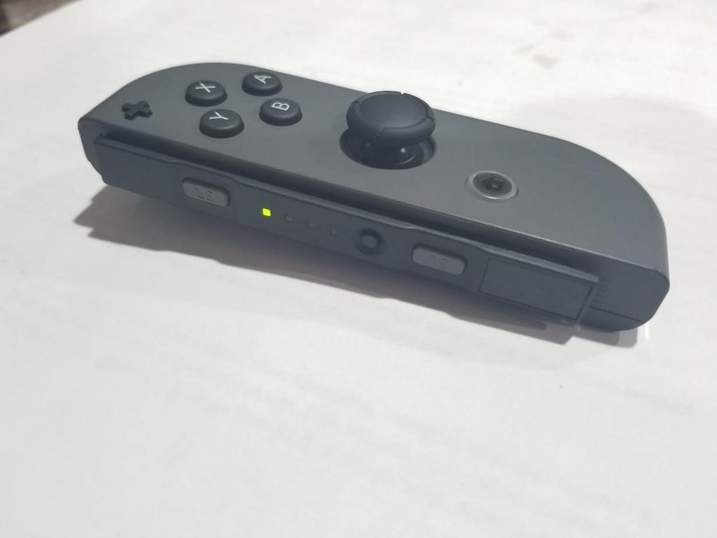
1 Team Xecuter Joycon Mod By: XxWiReDxX Works With Every Switch SX OS Works with every Nintendo Switch and every firmware version! Play Every Game With SX OS you can play all your favorite games straight off of the microsd card inserted into your Nintendo Switch. Homebrew Games & Apps Using SX OS homebrew menu launcher you can enjoy all the quality games and software created by independent developers. Continued Support Team Xecuter is always actively working to bring more exciting features to SX OS. Dual Functionality Using the SX OS Launcher you can easily boot into the normal Nintendo Switch firmware to enjoy your original games. How it Works / How to Use If your modified Joycon button is installed properly, with your Switch powered off, press and hold the Mod Button and Volume Up+. While holding these 2 buttons, power the Switch on with the power button. (If you see the Nintendo logo, it did not boot properly. If it boots to a blank black screen, you are now in RCM and have access to the bootloader. If you are using Xecuter's CFW, then you should boot into SX OS automatically). 1
2 Starting Notes 1. Take your time. Do not rush through the project. The JoyCon hardware is sensitive (Ribbon Cables can come loose if pulled hard) and the components are small. 2. Measure twice and Mod once. Make sure the placement of you button is in a location free of the existing hardware to ensure the device closes back up again. 3. A little goes a long way. When you are glueing or securing your button, use just a small amount of adhesive to prevent freezing up the momentary button. Recommended Supplies 1. Adhesive o Hot glue and Hot glue Gun OR o Liquid-Plastic Welding Tool Pen ( I have not tested this yet. 2. 6x6 Push Button Switch ( For $10.00 it is worth getting various button heights. 3. Wire and Connector (I recommend a connector to easily connect and disconnect from the button). o Female to Female 4 Inch Solderless Ribbon Dupont Jumper Wires (This is what I used) OR o Wire and solder 4. Soldering Iron (Try and use a fine tip soldering iron for lower heat and better control) & Solder. 5. Drilling Device o Dremel with a bit slightly larger than the button of the switch OR o Drill with a bit slightly larger than the button of the switch. 6. Shrink Tubing ( I recommend getting a kit of various sizes at $ Heat Gun or Lighter (Used for the Shrink Tubing). 8. Solder Flux (Optional, but it helps solder flow). 9. Security Screw Driver Set (YBit & Phillips used to open the JoyCon). I used my own set, but here is a link to one ( 10. Right JoyCon controller. (This will not work with the left JoyCon) Disclaimer Please keep in mind that I am not responsible for any issues caused by this modification. With that said, follow instructions and you should be okay. 2
.")
3 HOW TO Prep the Jumper/Connector Wire On my project I used a female jumper cable (link above). (Image 1 - Female Jumper) 3
. The housing is to long for the pins on the switch to reach the metal connector, so it must go! Do this twice. You will need two wires.")
4 1. Remove the female housing from the jumper. I used a small Philips screwdriver to get under the locking tab to lift it up and free it from the crimp connector. Lift the tab up and slide the connector off (Images 2-4). The housing is to long for the pins on the switch to reach the metal connector, so it must go! Do this twice. You will need two wires. (Image 2 - Lifting the Locking Tab) 4


5 (Image 3 - Removing the Jumper Housing) (Image 4 - Jumper Housing Removed) 5

6 2. Measure the protective shrink tubing before cutting. (Image 5 - Measuring the Shrink Tubing) 6

7 3. Cut the shrink tubing x2 for the two wires. (Image 6 - Cut Shrink Tubing) 7
. (Image 7 - Heated Shrink Tubing) Prep the Momentary Switch On my project I used a simple pushbutton momentary switch (Images 8-9 - link above).")
8 4. Slide the shrink tubing around the crimp connector, covering all exposed metal, and apply light heat with a heat gun or lighter to shrink the tube around the connector. It should look like (Image 7). (Image 7 - Heated Shrink Tubing) Prep the Momentary Switch On my project I used a simple pushbutton momentary switch (Images link above). 8
 (Image")
 9")
9 (Image 8 - Momentary Switch - Top) (Image 9 - Momentary Switch - Side & Bottom) 9
.")
10 1. Verify which posts you are going to use. Most of these switches use the two side post in pairs, resulting in two circuit paths for one switch (Essentially you can control two devices with one switch). If your switch came with a wiring diagram, refer to that, or you can always do a connectivity test with a multimeter (Image 10) or even a battery & led. (Image 10 - Multimeter and Momentary Switch) 10
.")
11 2. Remove unused side posts to prevent unnecessary exposure (Image 11). (You can bend them back and forth until they break, which is fairly easy). (Image 11 - Momentary Switch with Side Posts Removed) 11
.")
12 3. Straighten the remaining posts out to the side as seen in (Image 12). (Be very careful to not break them. Bend them in warm conditions if possible and slowly. Try to only bend them once). (Image 12 - Momentary Switch with Side Posts Bent Straight) 12

13 4. Test the connection with your fabricated jumpers to make sure they fit right. (Image 13) (Image 13 - Momentary Switch Connected to Jumpers) 13
. Set them in a secure location so you do not lose them and then carefully remove the back as in (Image 14).")
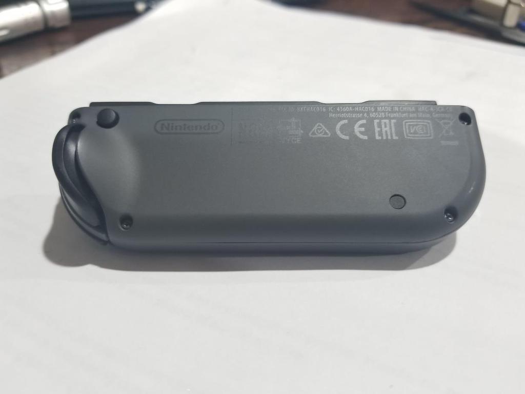
14 Prep the JoyCon Back 1. Remove the 4 YBit Screws from the back of the JoyCon. (You may have to press hard and turn slowly to initially break them free. Be very careful not to strip them). Set them in a secure location so you do not lose them and then carefully remove the back as in (Image 14). (Image 14 - JoyCon Back Removed) 14
. I fully disconnected mine as seen in (Image 15), but I do not recommend it. (Image 15 - JoyCon Slide Connector Board Fully Removed) 3.")
15 2. Use a Phillips screwdriver to remove the JoyCon slide connector board in (Image 15) and then carefully slide it off the main housing without disconnecting the ribbon cables (It should just fold over). I fully disconnected mine as seen in (Image 15), but I do not recommend it. (Image 15 - JoyCon Slide Connector Board Fully Removed) 3. Mark the back of the JoyCon controller to where you are going to drill the button hole. Use the switch to help find the proper location (Image 16). (I recommend tight to the rumble housing, the rectangle box, all the way to the back before the case curves). Once you have marked your drilling location, drill the hole in the back of the JoyCon (Use the low speed setting, and drill slow. You do not want the plastic to melt). In (Image 17) I drilled my hole a little to far too the left, but it still works. 15
 (Image 17 -")

16 (Image 16 - Using Momentary Switch to Find the Drill Location) (Image 17 - Drilled Hole on the Back of the JoyCon Controller (A Little too Far to the Left)) 16

17 4. Ensure your momentary switch button properly fits in the drilled hole. If it does not slowly increase the hole size with a larger bit or sandpaper. Connect the Momentary Switch to the JoyCon Back On my project I used a hot glue gun. I really wanted to give the recommended UV glue a go, but I was currently out. 1. Place your momentary switch in the intended place orientated with the pins toward the JoyCon slide connector board. While holding it in place, apply a small amount of adhesive to the most exposed and easiest accessed side. Hold until set. Once the momentary switch is tacked in place, continue to secure the rest of the sides like in (Image 18). (Image 18 - Momentary Switch Secured with Hot Glue) 17

18 Connect the Jumper Wires to the JoyCon Slide Connector Board 1. Measure the length of wire you need to cut off of your jumper wires to properly connect the JoyCon Slide Connector Board to the momentary switch. (I recommend leaving just a little bit of room for error). Once you have your measurement, cut your wire and strip the ends exposing just a mm long (This will reduce the error of over exposed wire shorting). 2. Prep your wire to be soldered to the JoyCon Slide Connector Board by pre-soldering the wire as seen in (Image 19). (I use flux to help the solder flow, but it is especially useful when soldering the jumper wire to the JoyCon board) (Image 19 - Jumper Wire with Soldered Ends) 18


19 3. Find the locations on the JoyCon Slide Connector Board that you are going to solder to. I used a voltmeter to find the solder posts for pins 1 & 10 (Images 20-21), which will be what we will solder to. (Image 20 - Testing Pins to Find the Associated Solder Posts) (Image 21 - Solder Posts for Pins 1 & 10 Circled in Red) 19
.")
20 4. Solder the jumper wires to the located solder posts with a soldering iron like in (Images 22-23) (I recommend using flux). (Be very cautious of the ribbon cable and plastic and only using the soldering iron for short bursts to prevent burning or melting). (Image 22 - Jumper Wires Soldered to the JoyCon Slide Connector Board) 20
 21")
21 (Image 23 - Jumper Wires Soldered to the JoyCon Slide Connector Board) 21
 2. Button the JoyCon controller back up.")
22 Connect and Close Everything Up 1. Connect the jumpers to the momentary switch and then screw the JoyCon Slide Connector Board back to the JoyCon back plate as seen in (Image 24). (Image 24 - JoyCon Slide Connector Board Connected to the Momentary Switch and JoyCon Back) 2. Button the JoyCon controller back up. It may take some playing around with to close them together, so be patient. It should never take excessive force to close them together. If you cannot close them, look to see if there is something catching and make the movements or adjustments needed. (I needed to trim some hot glue and slide the wires as close to the rumble pack box as I could). Once you have it all connected together, reinstall the 4 security screws you placed off to the side. 22
23 Congratulations! You re Done! 23
Instructions for Lighting an S Scale Caboose
 Instructions for Lighting an S Scale Caboose The S Scale Caboose lighting kit is adaptable for most caboose models of rolling stock including American Flyer (TM) and contains the same components as found
Repairing Microsoft Wedge Touch Mouse Battery Cover Retaining Clip
 Repairing Microsoft Wedge Touch Mouse Battery Cover Retaining Clip Disassembly, repair and reassembly of Wedge Touch mouse when the battery cover will not stay closed. Also is a good guide to repair other
PS4. Ragnarok Flex Modchip Installation Instructions.
 PS4 Ragnarok Flex Modchip Installation Instructions Revised 11/25/2013 Tools needed PS4 Controller Viking PS4 Ragnarok Flex modchip DIY Kit (includes mod chip, LED board, and LED lense) Two diodes (included
U-bass Kit Assembly Instructions
 U-bass Kit Assembly Instructions Compiled by playubass.com This guide is built from the instructions found here: http://kalabrand.com/ubass-kit/index.html Tools Needed 5/8 (16 mm) Wrench 7/16 (~11 mm)
Telecaster Wiring Kits Please Read All Instructions Before Beginning. Tools you will need: Soldering tips: Removing Current Wiring: Step 1. Step 2.
 Telecaster Wiring Kits Please Read All Instructions Before Beginning. Tools you will need: Soldering Iron (35 watt preferably) Solder Wet Sponge Wire Clippers Wire Strippers 3/8 Drill Bit 5/32 Drill Bit
Installation tutorial for Console Customs Xbox 360 Dual Rapid fire Microchip for wired and wireless controllers (all versions)
") Installation tutorial for Console Customs Xbox 360 Dual Rapid fire Microchip for wired and wireless controllers (all versions) This tutorial is designed to aid you in installation of a console customs
Installation tutorial for Console Customs Xbox 360 Dual Rapid fire Microchip for wired and wireless controllers (all versions) This tutorial is designed to aid you in installation of a console customs
GEN II Toyota Prius Back Door Opener Switch Replacement & License Plate Lights
 GEN II Toyota Prius Back Door Opener Switch Replacement & License Plate Lights Rubber Surface of Switch had Degraded to Tar-like Substance Vehicle Manufacture Date 10/06 OLD SWITCH IN GARNISH SWITCH REMOVED
Daytime Running Lights - Splice-in (10-12 All):
:") Time Necessary: Approximately 1 hour Tools Required: Heat Gun Installation Procedure: Daytime Running Lights - Splice-in (10-12 All): 1. It is recommended that the positive terminal be removed from the
Time Necessary: Approximately 1 hour Tools Required: Heat Gun Installation Procedure: Daytime Running Lights - Splice-in (10-12 All): 1. It is recommended that the positive terminal be removed from the
Mac mini Model A1176 SSD Installation
 Mac mini Model A1176 SSD Installation Installing an SSD in the Mac Mini A1176 Written By: Dozuki System 2017 guides.crucial.com Page 1 of 13 INTRODUCTION Upgrade your hard drive for more storage capacity.
Ribcage Installation. Part 2 - Assembly. Back-Bone V1.06
 Ribcage Installation Part 2 - Assembly Back-Bone V1.06 Contents Section 1 Before You Get Started... 2 Included With Your Kit:... 2 Figure: A... 3 CAUTION!... 4 Note:... 4 Tools Required... 5 Section 2:
Installation tutorial for Console Customs Xbox Mode Dual Button (RFX-5B) Rapid fire Microchip for all Wired and Wireless controllers
 Rapid fire Microchip for all Wired and Wireless controllers") Installation tutorial for Console Customs Xbox 360 5-Mode Dual Button (RFX-5B) Rapid fire Microchip for all Wired and Wireless controllers This tutorial is designed to aid you in installation of a console
Installation tutorial for Console Customs Xbox 360 5-Mode Dual Button (RFX-5B) Rapid fire Microchip for all Wired and Wireless controllers This tutorial is designed to aid you in installation of a console
Installation tutorial for Console Customs PS3 TrueFire Standard Rapid fire Microchip for Sixaxis and Dualshock 3 controllers
 Installation tutorial for Console Customs PS3 TrueFire Standard Rapid fire Microchip for Sixaxis and Dualshock 3 controllers This tutorial is designed to aid you in installation of a console customs rapid
PSU for LawMate 500mW Transmitters. Assembly and Operation Manual
 PSU for LawMate 500mW Transmitters Assembly and Operation Manual Introduction Thank you for purchasing LawMate 500mW Power Supply. This power supply was specifically designed for the 500mW LawMate transmitter
Never power this piano with anything other than a standard 9V battery!
 Welcome to the exciting world of Digital Electronics! Who is this kit intended for? This kit is intended for anyone from ages 13 and above and assumes no previous knowledge in the field of hobby electronics.
BrewsBySmith.com STC DIY Kit
 BrewsBySmith.com STC-1000 + DIY Kit Contact Information: Greg Smith www.brewsbysmith.com greg@boostbysmith.com I. Hardware Included: STC-1000 flashed with latest software (v1.06 currently) (if purchased)
Hardware Installation. Do this first:
 1 Do this first: Hardware Installation Need some help? Here s what you ll need: 4 AA Batteries Phillips screwdriver Visit us online. support.remotelock.com We re here to help. 1 (877) 254 5625 support@remotelock.com
Custom Front Panel Upgrade Instructions
 Custom Front Panel Upgrade Instructions Here are the directions for upgrading your SP-II to an SP-IIB, with a custom blackanodized front panel and engraved lettering. There are only forty SP-IIB s in existence
Written By: Brett Hartt
 Replace the battery in your ipad 3 4G. Written By: Brett Hartt ifixit CC BY-NC-SA www.ifixit.com Page 1 of 36 INTRODUCTION When your ipad can't stay awake for longer than a few hours, it is time to replace
PSU V2 for LawMate 500mW Transmitters. Assembly and Operation Manual
 PSU V2 for LawMate 500mW Transmitters Assembly and Operation Manual Introduction Thank you for purchasing the V2 LawMate 500mW Power Supply. This power supply was specifically designed for the 500mW LawMate
7878 K940. Checkpoint Antenna. Kit Instructions. Issue B
 7878 K940 Checkpoint Antenna Kit Instructions Issue B Revision Record Issue Date Remarks A July 7, 2009 First issue B Nov2013 Revised the Checkpoint installation procedures for 7878 and 7874 scanners Added
Section 5 BATTERY REPLACEMENT
 u Section 5 BATTERY REPLACEMENT j i 5.1 General The internal battery is used for preserving the clock and programming memory in the models 5000 and 7000. I i The procedure for each is given separately.
Pacific Antenna 20 and 40M Lightweight Dipole Kit
 Pacific Antenna 20 and 40M Lightweight Dipole Kit Diagram showing configuration and approximate lengths 8 6 16 9 16 9 8 6 Description The Pacific Antenna lightweight dual band, trap dipole kit provides
iphone 1st Generation Battery Replacement Written By: irobot ifixit CC BY-NC-SA Page 1 of 15
 Written By: irobot ifixit CC BY-NC-SA www.ifixit.com Page 1 of 15 INTRODUCTION Battery not lasting long? Swap it out (requires soldering). TOOLS: Probe and Pick Set (1) Desoldering Braid (1) SIM Card Eject
ARP AVATAR PATCH PANEL INSTALLATION MANUAL
 ARP AVATAR PATCH PANEL INSTALLATION MANUAL Introduction Thank you for purchasing an Avatar Patch Panel Kit! These instructions are intended to guide you through installing and using this kit. Before we
Catch The Bug. Body Build. Where are we? Process # You are. here.
 Catch The Bug Body Build Process # 1 Where are we? 1) Body Build- The mechanical part of the bug is constructed. 2) Electronics Lab- Bug Experiments teach the fundementals of electronics. 3) Final Wiring-
Cabinet Mount Lifter Instructions
 PART LIST 2 @ Side Pivot Arms 1 @ Coupler Tube 1 @ Left Hand Bracket 1 @ Right Hand Bracket 2 @ Cover Support Arms w/ Foam Grip 1 set of Cover Saver 4 @ 4 Wood Screw 8 @ 1 Wood Screw 12 @ 1 Black Tek Screw
Iphone 5 Glass/Lcd REPAIR GUIDE. Version Edition
 Iphone 5 Glass/Lcd REPAIR GUIDE Version 1 2016 Edition IPhone 5 Glass/LCd REPAIR GUIDE RiAna Soto Repair Training Specialist rsoto@cellairis.com FOR EVERY REPAIR MAKE SURE TO COMPLETE, INITIAL, AND HAVE
Harmony Remote Repair
 Harmony Remote Repair harmonyremoterepair.com How to install your new Harmony One Front Cover/Touch Screen Important! Before you begin working on your Harmony One, you must discharge any static electricity
Written By: Ben Eisenman
 iphone 3GS Front Panel Replacement Replace a cracked front panel on an iphone 3GS. Written By: Ben Eisenman ifixit CC BY-NC-SA www.ifixit.com Page 1 of 18 INTRODUCTION Use this guide to separate and replace
Asus ZenFone 2 Display Replacement
 Asus ZenFone 2 Display Replacement Replace your display if it isn't functioning correctly or if it is cracked or broken. Written By: Jessica Nguyen ifixit CC BY-NC-SA www.ifixit.com Page 1 of 14 INTRODUCTION
Written By: Andrew Optimus Goldberg
 Replace the screen your GSM/AT&T iphone 4. Written By: Andrew Optimus Goldberg ifixit CC BY-NC-SA www.ifixit.com Page 1 of 25 INTRODUCTION [video: http://www.youtube.com/watch?v=obpfpfx5abw] Use this guide
The brackets have been tested on the 2017 and 2018 versions of the Spirit Proton pack and also with two separate A.L.I.C.E.
 Introduction Congratulations on purchasing the Spirit Brackets Kit that allows very secure attachment of an A.L.I.C.E. pack frame to your Spirit Halloween Proton Pack. The Spirit Brackets Kit is designed
Installation tutorial for Console Customs Xbox 360 MaxFire LITE rapid fire Mod Chip.
 Installation tutorial for Console Customs Xbox 360 MaxFire LITE rapid fire Mod Chip. This tutorial is designed to aid you in installation of a console customs MaxFire LITE modchip. This tutorial covers
EmagiKit. Privacy Pod Plus. Quiet. Easy. Affordable. INSTRUCTIONS ASSEMBLY
 EmagiKit Privacy Pod Plus Quiet. Easy. Affordable. INSTRUCTIONS ASSEMBLY DIMENSIONS AND COMPONENTS 47 47 Ceiling Unit 2-B 2-L 2-R Glass Door Corner Trim Door Handle 90 Adjustable Height Work Surface 1-B
Pacific Antenna 20 and 40M Lightweight Dipole Kit
 Pacific Antenna 20 and 40M Lightweight Dipole Kit Antenna diagram showing configuration and lengths when assembled 7 8 16 9 16 9 Description The Pacific Antenna lightweight dual band dipole kit provides
3 Shielded Compact Ribbon (SCR) Wiremount Plug, XX, and Shell Kit, F200-XXX
 Wiremount Plug, XX, and Shell Kit, F200-XXX") 3 Shielded Compact Ribbon (SCR) Wiremount Plug, 36110-3000XX, and Shell Kit, 36310-F200-XXX Instructions June 2007 78-9100-4282-5 General This instruction manual explains the method of assembling the 3M
3 Shielded Compact Ribbon (SCR) Wiremount Plug, 36110-3000XX, and Shell Kit, 36310-F200-XXX Instructions June 2007 78-9100-4282-5 General This instruction manual explains the method of assembling the 3M
Star Trek TOS communicator upgrade kit Install instructions Hyperdyne Labs 2002
 Star Trek TOS communicator upgrade kit Install instructions Hyperdyne Labs 2002 Package Your package should include: Assembled TOS sound/motor/light board with LEDs and sound chip Moiré motor 9V snap connector
ScaleRCHelis.com V Light Controller Kit
 Thank you for purchasing the ScaleRCHelis.com V1.1 450 Light Controller Kit. This is something you can build in under a hour with some simple soldering equipment. Your kit will include all the parts necessary
The Useless Machine. Parts Only - Build Guide v0001
 TM The Useless Machine Parts Only - Build Guide v0001 For the best outcome, follow each step in order. We recommend reading this guide entirely before you get started. Tools required: One phillips screwdriver,
Warm Tube Clock. Before we start, please make sure that you have all required parts that come for the IN-16 Nixie shield :
 Warm Tube Clock Assembly Instructions for the IN-16 Nixie shield Introduction Congratulations on your purchase of OSH Nixie Tube Clock. In this document you will see all steps you need to follow in order
Installation tutorial for Console Customs Xbox ONE MaxFire ONE V2 PCB
 Installation tutorial for Console Customs Xbox ONE MaxFire ONE V2 PCB This tutorial is designed to aid you in installation of a console customs MaxFire ONE V2 Circuit board in the newer Xbox One Controllers
The Useless Machine. DIY Soldering Edition. Instruction Guide v0004
 The Useless Machine DIY Soldering Edition Instruction Guide v0004 TM For the best outcome, follow each step in order. We recommend reading this guide entirely before you get started. Tools required: Soldering
Nano v3 pinout 19 AUG ver 3 rev 1.
 Nano v3 pinout NANO PINOUT www.bq.com 19 AUG 2014 ver 3 rev 1 Nano v3 Schematic Reserved Words Standard Arduino ( C / C++ ) Reserved Words: int byte boolean char void unsigned word long short float double
2 Recommended Tools / Supplies
 Bias Scout TM Kit Assembly Manual Version 3.1 25 March 2015 1 Inventory of Parts 1 ea octal socket 1 ea octal base, brown (1 3/16" dia x 7/8" high) 1 ea 1.0 / 1W metal oxide, flame proof resistor 1 ea
Removing and Replacing the Y-truck
 Service Documentation Removing and Replacing the Y-truck To remove and replace the Y-truck you will need the following tools: 4mm Allen wrench 12mm stamped flat wrench #2 Phillips screwdriver (magnetic
ipad 2 GSM Right Cellular Data Antenna Replacement
 ipad 2 GSM Right Cellular Data Antenna Replacement Replace the right cellular data antenna in your ipad 2 GSM. Written By: Brett Hartt ifixit CC BY-NC-SA www.ifixit.com Page 1 of 43 INTRODUCTION Use this
SeeMeCNC Guides. Rostock Max v1/v2 HE280 Hotend Upgrade. This How-to Guide will walk you through the steps of upgrading to the HE280 Hotend.
 SeeMeCNC Guides Rostock Max v1/v2 HE280 Hotend Upgrade This How-to Guide will walk you through the steps of upgrading to the HE280 Hotend. Written By: SeeMeCNC 2018 seemecnc.dozuki.com/ Page 1 of 33 Step
unit 3: GENErAL ElectriCAL SySTEM DiAGNOSiS
 Electrical/Electronic Systems unit 3: GENErAL ElectriCAL SySTEM DiAGNOSiS lesson 4: wire and connector repairs I. Connector repairs A. Connector repairs involve fixing damaged wires. Wires are marred due
05-17 Mustang Fuel System Wire Upgrade Installation
 PARTS LIST: -10AWG INLINE FUSE HOLDER WITH 30AMP BLADE FUSE -16FT 10AWG HIGH CURRENT PRIMARY WIRE -40AMP AUTOMOTIVE RELAY -1FT 10AWG GROUND WIRE -1FT 10AWG HIGH CURRENT PRIMARY WIRE OUTPUT TO FPDM -1FT
RH-412 STEEL DOORS INSTALLATION INSTRUCTIONS
 RH-412 STEEL DOORS INSTALLATION INSTRUCTIONS By following the steps outlined below, the assembly, installation and adjustment of the steel doors, will be a simple process. Let s start with the Driver Side.
Written By: Walter Galan
 Replace the small antenna attached to the headphone jack of your iphone 4S. Written By: Walter Galan ifixit CC BY-NC-SA www.ifixit.com Page 1 of 23 INTRODUCTION Use this guide to replace your iphone's
ipad 3 4G Home Button Control Board Replacement
 ipad 3 4G Home Button Control Board Replacement Replace the home button control board in your ipad 3. Written By: Brett Hartt ifixit CC BY-NC-SA www.ifixit.com Page 1 of 28 INTRODUCTION This guide will
Pacific Antenna 20 and 40M Lightweight Dipole Kit
 Pacific Antenna 20 and 40M Lightweight Dipole Kit Diagram showing configuration and approximate lengths 8 3 16 9 16 9 8 3 Description The Pacific Antenna lightweight dual band, trap dipole kit provides
Explorer Wiring Kit (assembled)
") Explorer Wiring Kit (assembled) For Vintage, Firestorm & Standard Series Please Read All Instructions Before Beginning. Tools you will need: Soldering Iron (35 watt preferably) Solder Wet Sponge Wire Clippers
Explorer Wiring Kit (assembled) For Vintage, Firestorm & Standard Series Please Read All Instructions Before Beginning. Tools you will need: Soldering Iron (35 watt preferably) Solder Wet Sponge Wire Clippers
21st Century Fashion Kit: Inflation
 Page 1 of 6 21st Century Fashion Kit: Inflation CONTRIBUTORS: DIA, MEMBER #313449 Introduction Inflatables are a great way to make fashion that transforms shape, or has a large exaggerated silhouette.
ipad 3 4G Home Button Assembly Replacement
 ipad 3 4G Home Button Assembly Replacement Replace the home button assembly in your ipad 3 4G. Written By: Brett Hartt ifixit CC BY-NC-SA www.ifixit.com Page 1 of 29 INTRODUCTION Use this guide to replace
Circuit Board Assembly Instructions for Babuinobot 1.0
 Circuit Board Assembly Instructions for Babuinobot 1.0 Brett Nelson January 2010 1 Features Sensor4 input Sensor3 input Sensor2 input 5v power bus Sensor1 input Do not exceed 5v Ground power bus Programming
Written By: Brett Hartt
 ipad 3 4G LCD Replacement Removing the LCD Written By: Brett Hartt ifixit CC BY-NC-SA www.ifixit.com Page 1 of 25 INTRODUCTION The third generation ipad loses a lot of luster when its gorgeous retina display
Standard Kit #1 (3-way switch)
") Standard Kit #1 (3-way switch) Please Read All Instructions Before Beginning. Tools you will need: Soldering Iron (35 watt preferably) Solder Wet Sponge Wire Clippers 3/8 Drill Bit 1/4 Drill Bit Variable
Standard Kit #1 (3-way switch) Please Read All Instructions Before Beginning. Tools you will need: Soldering Iron (35 watt preferably) Solder Wet Sponge Wire Clippers 3/8 Drill Bit 1/4 Drill Bit Variable
WARNING. BX Jeep Liberty Installation Instructions. Serial Number
 Please read BOTH these and the General Towing Instructions before attempting to install or operate this equipment. 1. Blue Ox towing products and accessories are intended to be installed by Blue Ox Dealers
Installing Your New Creature From The Black Lagoon Tail Light DMD Panel MOD
 Installing Your New Creature From The Black Lagoon Tail Light DMD Panel MOD A few things before we start: The wooden speaker panel provided in this MOD was manufactured using a Precision CNC machine and
QUALITY MANAGEMENT SYSTEM
 Not controlled in hard copy Rev. 1.0 Date: Page 1 of 18 Subject The following instructions provide a step-by-step procedure to replace the heating element for DEF/SCR/UREA/ADBLUE/DIESEL After Treatment
C-Bot. User Guide. Cautionary and Warning Statements
 C-Bot User Guide Cautionary and Warning Statements This kit is designed and intended for educational purposes only. Use only under the direct supervision of an adult who has read and understood the instructions
WARNING: Prior to installation, turn the power off to the vending machine and unplug it from its power source. Also, make sure to level the machine.
 Installation of Gum and Mint Tray for National 147, 157, 167 Important Note: Please read all instructions thoroughly before continuing with installation of kit. If you are having problems installing the
Written By: Walter Galan
 iphone 4S Logic Board Replacement Replace a dead logic board in your iphone 4S. Written By: Walter Galan ifixit CC BY-NC-SA www.ifixit.com Page 1 of 22 INTRODUCTION Use this guide to replace your iphone's
INSTALLING YOUR NEW SPRING LIFT ARM KIT
 INSTALLING YOUR NEW SPRING LIFT ARM KIT 1. Measure the distance that the roof is to be raised. [If your lift system is completely non-functional, you will need to calculate or estimate this distance as
Repairing Apple Wireless Keyboard without destroying it.
 Repairing Apple Wireless Keyboard without destroying it. An Apple keyboard with non-functioning keys may be due to damaged traces on the two thin sheets of plastic inside, called the membrane. This is
Pacific Antenna RF Probe assembly
 Pacific Antenna RF Probe assembly Parts In the Kit: 1 1/2 x 3 Blue PEX tube 2 5/8 O.D. vinyl caps 2 3/32 dia x 2 brass tube sections 2 Pogo spring contacts 1 4-40 x 7/16 pan head screw 1 4-40 x 1/4 pan
Written By: Walter Galan
 Replace the logic board in your ipad 3 Wi-Fi. Written By: Walter Galan ifixit CC BY-NC-SA www.ifixit.com Page 1 of 29 INTRODUCTION Use this guide to replace the logic board. TOOLS: iopener (1) Phillips
LP-200 Dummy Load / Wattmeter
 LP-200 Dummy Load / Wattmeter Enclosure Retrofit Assembly Instructions March 2009 TelePost Incorporated LP-200 is a trademark of TelePost Inc. Material in this document copyrighted 2009 TelePost Inc. 1
SIGNATURE FRONT BUMPER INSTALL
 SIGNATURE FRONT BUMPER INSTALL JL **PLEASE READ THROUGH THE INSTRUCTIONS BEFORE BEGINNING ANY PART OF THE INSTALLATION PROCESS** 1. You can now remove the trim strip (2 vertical clips, 4 horizontal, 2
Written By: Jeff Suovanen
 iphone XS Max Lower Speaker Replacement Remove or replace the main loudspeaker on the bottom edge of the iphone XS Max. Written By: Jeff Suovanen ifixit CC BY-NC-SA www.ifixit.com Page 1 of 23 INTRODUCTION
WARNING. BX Ford Explorer With Adaptive Cruise Control & Eco Boost Installation Instructions
 Please read BOTH these and the General Instructions before attempting to install or operate this equipment. 1. Blue Ox towing products and accessories are intended to be installed by Blue Ox Dealers who
POWERPOLE CONNECTORS. Fountain Valley RACES 05 Feb 2008
 POWERPOLE CONNECTORS Fountain Valley RACES 05 Feb 2008 ACCESORIES SPLITTER WITH OEM T-CONNECTOR ACCESSORIES RED DEE 2 SPLITTER Any connection point is an input / any connection point is an outlet ACCESSORIES
CommScope Tool-less IDC Instruction Sheet Connector Block Issue 3, February 2004 Material ID
 CommScope Tool-less IDC 201-208-101-02 Instruction Sheet Connector Block Issue 3, February 2004 Material ID 848 586 103 General This instruction sheet provides general procedures for mounting Tool-less
Applications: Section 1: Getting Started Tools Needed: BEFORE
 Installation of KBD Body Kits Porsche GT 3 Look/Style 2 Piece Polyurethane Front Bumper & Lip Applications: Porsche 996: 1999-2001 Porsche Boxster 986: 1997-2004 Page 1 Tools Needed: Philips Head Screwdriver
Congratulations on purchasing the Spirit Rails Magnetic Attach that allows easy wand to pack removal and reattachment by just getting close!
 Introduction Congratulations on purchasing the Spirit Rails Magnetic Attach that allows easy wand to pack removal and reattachment by just getting close! The Spirit Rails Magnetic Attach Kit is designed
Installation Instructions Road King Classic Saddlebag Bezels
 Installation Instructions Road King Classic Saddlebag Bezels Thank you for your purchase of Bagger Audio Road King Classic Saddlebag Bezels for your Harley-Davidson motorcycle. We have carefully engineered
& ' (wire, inches) 16 black Tef-Flex 16 Black Lex 32 Red Lex 48 Blue Tef-Flex 32 White Tef-Flex
 16 black Tef-Flex 16 Black Lex 32 Red Lex 48 Blue Tef-Flex 32 White Tef-Flex") ! " # $! " % Qty Part (woofer) 1 4.40mH 16 AWG inductor 1 10.0uF Yellow film capacitor 1 5.62 Ohm NORTH resistor (tweeter) 1 8uF Yellow film capacitor 1 0.56mH 16 AWG inductor 1 3.32 Ohm NORTH resistor
! " # $! " % Qty Part (woofer) 1 4.40mH 16 AWG inductor 1 10.0uF Yellow film capacitor 1 5.62 Ohm NORTH resistor (tweeter) 1 8uF Yellow film capacitor 1 0.56mH 16 AWG inductor 1 3.32 Ohm NORTH resistor
tinycylon Assembly Instructions Contents Written by Dale Wheat Version August 2016 Visit dalewheat.com for the latest update!
 tinycylon Assembly Instructions Written by Dale Wheat Version 2.1 10 August 2016 Visit dalewheat.com for the latest update! Contents Assembly Instructions...1 Contents...1 Introduction...2 Quick Start
Hatchback Wing Riser Kit
 Hatchback Wing Riser Kit 2015-06-11 Thank you for purchasing this PERRIN product for your car! Installation of this product should only be performed by persons experienced with installation of aftermarket
Bushwacker Jeep Flat Style Fender Flares Front Pair
 Bushwacker Jeep Flat Style Fender Flares Front Pair Note: These instructions involve cutting parts of your vehicle. Please read all instructions prior to starting. Installation Time: 3-4 Hours Tools Required:
Repairing iphone 4 LCD Backlight Dim spot issue
 Repairing iphone 4 LCD Backlight Dim spot issue found a way to fix a liquid damaged iphone screen back light issue Written By: Pranav Singh ifixit CC BY-NC-SA www.ifixit.com Page 1 of 26 INTRODUCTION found
Written By: Brett Hartt
 Replacing the Wi-Fi antenna in the third generation ipad Written By: Brett Hartt ifixit CC BY-NC-SA www.ifixit.com Page 1 of 31 INTRODUCTION Wireless internet is awesome. A third generation ipad without
Repairing your Porsche 928 Central Warning System (CWS) controller
 controller") Repairing your Porsche 928 Central Warning System (CWS) controller Disclaimer: This procedure is for a 1984 Porsche 928 S controller. Overview: Under the left foot pedal (dead pedal) of the Porsche 928
Repairing your Porsche 928 Central Warning System (CWS) controller Disclaimer: This procedure is for a 1984 Porsche 928 S controller. Overview: Under the left foot pedal (dead pedal) of the Porsche 928
Written By: Sam Lionheart
 Replace the SIM Board in your ipad 4 GSM. Written By: Sam Lionheart ifixit CC BY-NC-SA www.ifixit.com Page 1 of 29 INTRODUCTION Use this guide to replace the SIM Board. TOOLS: SIM Card Eject Tool (1) iopener
gently pry up all your door switches.. disconnect them.. same with the mirror control on the drivers side..
 How To Recover Door Panels By: Crispy SUPPLY/TOOL LIST NEEDED Dremel with drill cutter attachment (or drill with drill bit) contact cement 1/2 inch self tapping screws Carpet/Headliner spray on glue Phillips
BX3615. Subaru Impreza WRX (Include STI) Subaru 2012 Impreza Premium 2010 Outback Sport Installation Instructions Attachment Tab Height: 15
 Subaru 2012 Impreza Premium 2010 Outback Sport Installation Instructions Attachment Tab Height: 15") 1. Blue Ox towing products and accessories are intended to be installed by Blue Ox Dealers who are familiar with our products and have the equipment and knowledge necessary to do fit work. If needed, Blue
1. Blue Ox towing products and accessories are intended to be installed by Blue Ox Dealers who are familiar with our products and have the equipment and knowledge necessary to do fit work. If needed, Blue
Growler Getter. Supplies: ½ yard main fabric. ½ yard Insul-Shine. 8 x 10 piece of Fusible Fleece 2. ¼ yard or fat quarter of coordinating fabric
 Supplies: ½ yard main fabric ½ yard Insul-Shine 8 x 10 piece of Fusible Fleece 2 ¼ yard or fat quarter of coordinating fabric 1 9 x 12 sheet of Steam-A-Seam 2 1 yard nylon cord 1 cord stop Coordinating
PAC-12 Kit Contents. Tools Needed Soldering iron Phillips screwdriver Wire stripper Wrenches, 7/16 and 1/2 Terminal crimp tool Pliers Solder
 PAC-2 Kit Contents Part Quantity Screws: 8/32 x 3/8 Screws: 8-32 x 5/6 Screw: 8-32 x /4 #8 internal tooth washers #8 solder lug ring terminals Bolt: Aluminum, /4-20 x.5 /4 internal tooth washer Nut: Aluminum
Please read BOTH these Installation Instructions and the General Instructions before attempting to install or operate this equipment.
 Please read BOTH these and the General Instructions before attempting to install or operate this equipment. 1. Blue Ox towing products and accessories are intended to be installed by Blue Ox Dealers who
Elecraft AF1 Audio Filter Enclosure
 Elecraft AF1 Audio Filter Enclosure by W8FGU Elecraft AF1 Audio Filter Mounted in the AF1 Enclosure (Courtesy of Ron D Eau Claire). The AF1 enclosure is made of Lexan, a polycarbonate, which is very strong.
INSTALLATION INSTRUCTIONS RH 412 STEEL DOORS
 By following the steps outlined below, the assembly, installation and adjustment of the steel doors, will be a simple process. Let s start with the Driver Side. Note: Having the hood open makes the job
Progeny Integrated Mobile Unit Unpacking/Assembly Guide
 Summary: The following instruction will guide you through the unpacking and installation of the Progeny Mobile Unit. Any question or concerns or suggestions should be directed to Progeny Technical Support
======================================================================================== ( DR / DR) JK WRANGLER MOD RACK
 JK WRANGLER MOD RACK") (10984 4DR / 10982 2DR) JK WRANGLER MOD RACK INSTALLATION SHEET Important Notes: Some brands of windshield light brackets and snorkels may not be compatible with the 10984 MOD Rack System. Body lifts are
(10984 4DR / 10982 2DR) JK WRANGLER MOD RACK INSTALLATION SHEET Important Notes: Some brands of windshield light brackets and snorkels may not be compatible with the 10984 MOD Rack System. Body lifts are
Mustang RTR Rear Diffuser Splitter Assembly Installation Instructions CDC#
 2010-2012 Mustang RTR Rear Diffuser Splitter Assembly Installation Instructions CDC# 1098-7006-01 About the Product: This product is designed by Classic Design Concepts, and installs using all factory
Pivot Frame Mounting Instructions
 A D E I J What Is In The Box B C F * Some Pivot Frames include Extra Spring Clips for Mat if spring clips are lost or to flatten mat in frame. G H Description QTY A. Pivot Frame 1 B. Upper Catch Bracket
Installation Instructions Jeep JL Front Grumper Product Number: GR4600 Application: 18+ JEEP JL
 ! IMPORTANT SAFETY GUIDE Your safety and the safety of others is very important. In order to help you make informed decisions about safety, we have provided the following warnings, safety precautions,
Darin Pitts Phoenix Arcade: How To - Tron Control Panel Overlay October 31, 2011
 Step 1: Flattening the Artwork Tron artwork purchased from Phoenix Arcade will be shipped rolled. At least one week prior to application the artwork should be laid out on a flat surface in order for the
Written By: Walter Galan
 Replace the Logic Board in your ipad 4 Wi-Fi. Written By: Walter Galan ifixit CC BY-NC-SA www.ifixit.com Page 1 of 32 INTRODUCTION Use this guide to replace the logic board. TOOLS: iopener (1) Phillips