Telecaster Wiring Kits Please Read All Instructions Before Beginning. Tools you will need: Soldering tips: Removing Current Wiring: Step 1. Step 2.
|
|
|
- Carmel Hawkins
- 6 years ago
- Views:
Transcription
 Solder Wet Sponge Wire Clippers Wire Strippers 3/8 Drill Bit 5/32 Drill Bit Phillips Screwdriver Pliers Small bowl to hold screws and knobs")

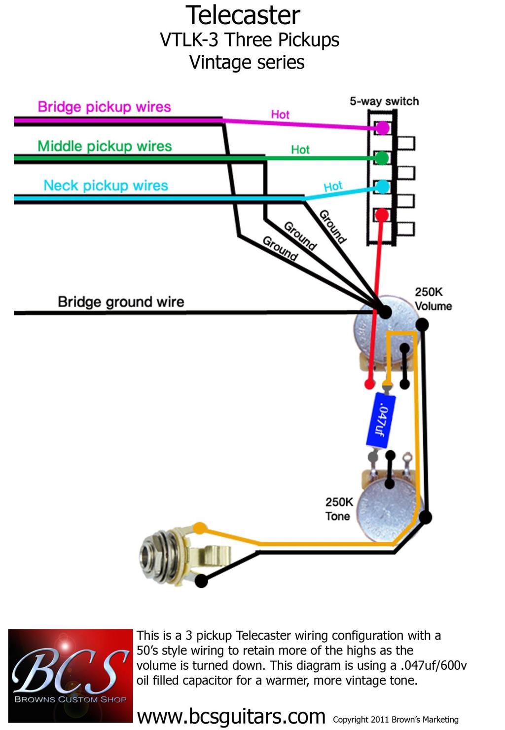
1 Telecaster Wiring Kits Please Read All Instructions Before Beginning. Tools you will need: Soldering Iron (35 watt preferably) Solder Wet Sponge Wire Clippers Wire Strippers 3/8 Drill Bit 5/32 Drill Bit Phillips Screwdriver Pliers Small bowl to hold screws and knobs ATTENTION: At the very least basic soldering skills are needed to install this kit. If you do not have these skills or are not confident enough in your skills to install this kit than please take it to someone who does, such as a certified guitar technician. Soldering tips: Remember to clean the tip of your soldering iron before soldering each connection, a dirty or bad solder joint can add excessive noise into your guitar, especially when using distortion. Be sure to apply a small amount of solder to your iron before trying to heat a connection, this will help your iron transfer heat better and the solder will flow faster Removing Current Wiring: Step 1. Place your guitar face up on a firm yet soft surface (a couple of bath towels on a bench or table will do) to keep your guitar from getting scratched. Step 2. Remove the knobs and switch tip from the controls. If your knobs are metal they may be held on with a set screw located on the side of the knob. Next, with the Phillips screwdriver remove the two screws on either end of the control plate and place the screws in a small bowl so they will not get lost. Now you can pull up the control plate to expose the wiring beneath. Step 3. Remove the jack plate. Remove the two screws on the side of the jack plate and then pull it away from the body. Next, remove the nut and pull the plate away from the jack. If your guitar does not have a screwed down plate but rather a push-in jack socket it would be best to leave the socket in place and remove the nut on the jack and then pull it into the control cavity. Once the jack sockets have been removed they don t like to stay in place. You may also consider replacing it with a screw down jack plate.


2 Step 4. Next you need to identify the pickup wires and the bridge ground wire. In this guitar the neck pickup wires are coming from the front of the cavity, and the bridge pickup wires are coming from the middle of the cavity. The small black wire coming out of the middle of the cavity with the bridge pickup wires is the bridge ground. The last wire coming out of the cavity in this photo is the output wire running to the jack. Use some tape to identify the pickup wires so they don t get switched when hooking them up to your new wiring kit. In this we used blue electricians tape for the neck and red for the bridge. Also notice that with these pickups the red and bare wires coming from the pickups are soldered to ground and the white wires are the hot that run to the switch. Step 5. After the wires have been identified go ahead and clip them from the old controls, but don t clip the wires going to the jack. You can now set the old controls aside and after you are finished with the installation you can mount them on the empty template and keep them if you like. After clipping the wires go ahead and prep them for installing your new kit. In this photo we trimmed the red wire all the way back to the bare ground wire, twisted them together, tinned all the exposed wire with solder and then covered it with heat shrink. We then trimmed all the wires back enough for connections and then tinned them. Step 6. Your control plate should be empty now. For your new kit to fit, the pot holes need to be 3/8 inch (9.52mm) in diameter and the switch holes need to be 5/32 inch (3.968mm) in diameter. If they are not the correct size you will need to drill them out. Step 7. Remove the new wiring kit from the template and then mount it to the control plate. Notice that there are two nuts on the pot shafts, the second nut is to adjust the height of the pot sticking out of the control plate on the other side. Adjust this for the proper height so your knob will sit properly and not be too high off of the control plate. Tighten down the nuts on the pots and the screws on the switch and make sure that everything is secure.
, then place the tinned wire on top of the")
. This will make it quick and hassle free to attach the wire to the pot.")

3 Time To Solder! NOTE: When soldering to the back of the pot first put a small bead of solder on the pot (or use a soldered joint that already exists on the back of the pot), then place the tinned wire on top of the bead of solder, and then using the tip of the iron heat both the wire and the bead of solder at the same time until the solder flows together and covers the wire. Remove the iron and hold the wire in place until the solder cools and hardens (feel free to blow on it). This will make it quick and hassle free to attach the wire to the pot. You do not want the iron on the components for too long or you will burn up the pot. NOTE: Notice that the lugs of the switch are covered in. When attaching wires to these points place the tip of the wire against the soldering point, touch the soldering iron to the wire and soldering point at the same time and push gently. When the solder heats up and flows the tip of the wire will push through the hole of the soldering point, remove the soldering iron quickly and the solder will cover the pin and wire and make a solid connection. If you hold the heat too long than the solder will run down the lug and could foul up the switch operation. Once the solder is cooled and the wire is held in place make sure that the wire coming out of the pin is not touching any other connections or small metal runs and trim with wire clippers if necessary. NOTE: Remember that the metal braiding on the outside of the wires is all connected to ground so they cannot touch any other connections or else your signal will die Step 8. Now to hookup the wires. The neck pickup hot wire solders to the first open lug at the forward position of the switch and the bridge pickup hot wire solders to the last open lug towards the rear of the switch. The pickup ground wires and the bridge ground wire solder to the back of either of the pots. NOTE: The kit used in this picture is the VTLK-1, if you are installing a different kit please see the wiring schematics at the end of these instructions for wire locations. Step 9. Before screwing down the control plate, feed the jack through the control cavity and out the jack hole. You can use a screw driver to help guide the jack out the hole, just stick the screwdriver through the hole and through the jack from the outside of the guitar and use it to hold the jack centered and then push it through the hole from the control cavity with the output wire. Then attach the jack to the jack plate. The jack also has an adjusting nut to set the height properly. Now insert a cable into the jack and make sure that it inserts and withdraws properly. If there is any problems getting the jack in, pull the slack of the output wire into the control cavity.
 and bend it out of position.")

4 Step 10. Now place the control plate back into place. Be careful as you put it in, make sure that the excess output wire does not bunch up beneath the capacitor (the blue component between the pots) and bend it out of position. Also make sure it does not bunch up under the tone pot or go back down the jack hole. If it bunches up under the tone pot it can make for a difficult fit, and if it goes down the jack hole it can prevent the guitar cable from inserting into the jack correctly. After the plate is in place screw it back down to the guitar body and then put the knobs and switch tip on the controls. Step 11. Your finished, so plug it in and take if for a test run. If something is not working properly go over the instructions and your connections again carefully and see if you can find the problem. Be sure that the braided wire is not touching anything other than ground. If you cannot find the problem us at customerservice@bcsguitars.com and we will get a technician to call you as soon as they are available and try to help you trouble shoot the problem. Other Telecaster Kits On the following pages you will find the wiring schematics and other notes for installing our other Telecaster kits. If you have any problems understanding the schematics, or any other problems with your installation please contact us and we will be happy to help. customerservice@bcsguitars.com Phone:
5
6
7
8
9
. On the bottom of the pickup you will see where the pickup wires are soldered to the coil wire and the pickup cover.")
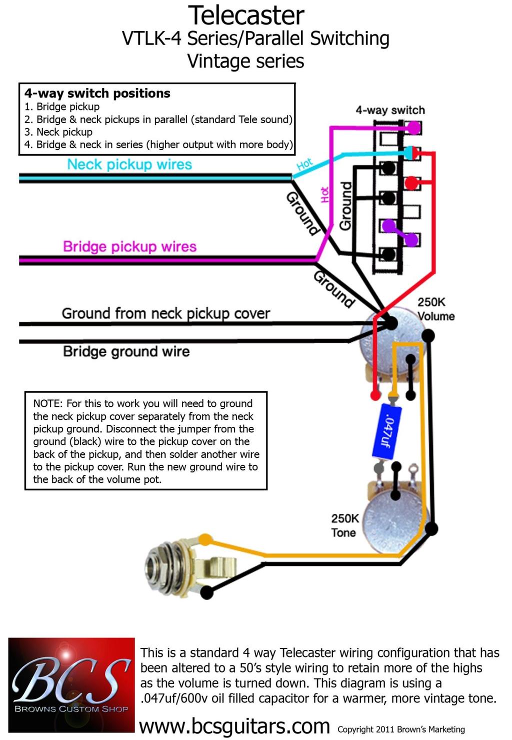
10 VTLK-4 4-way Series/Parallel Switching To complete this modification you will need to remove the neck pickup cover from the pickup ground wire and ground it with its own ground wire. Step 1. Remove the neck pickup from the guitar and the controls (switch and pot). On the bottom of the pickup you will see where the pickup wires are soldered to the coil wire and the pickup cover. The pickup cover has a tab sticking through the base of the pickup and there is a small jumper wire that connects it to the ground wire connection. Step 2. Remove the jumper wire that connects the pickup cover tab to the ground wire connection. To do this simply heat the jumper with your solder iron as soon as the solder begins to flow move the jumper wire away with the tip of the iron. Step 3. Solder a new ground wire to the pickup cover tab. Make sure the ground wire is long enough to reach one of the control pots so it can be grounded. NOTE: Be sure that there is no bits of solder connecting ANY of the three connections (Pickup cover tab, Hot wire connection & Ground wire connection), if there is you need to remove it before re-installing the pickup.
Explorer Wiring Kit (assembled)
") Explorer Wiring Kit (assembled) For Vintage, Firestorm & Standard Series Please Read All Instructions Before Beginning. Tools you will need: Soldering Iron (35 watt preferably) Solder Wet Sponge Wire Clippers
Explorer Wiring Kit (assembled) For Vintage, Firestorm & Standard Series Please Read All Instructions Before Beginning. Tools you will need: Soldering Iron (35 watt preferably) Solder Wet Sponge Wire Clippers
Standard Kit #1 (3-way switch)
") Standard Kit #1 (3-way switch) Please Read All Instructions Before Beginning. Tools you will need: Soldering Iron (35 watt preferably) Solder Wet Sponge Wire Clippers 3/8 Drill Bit 1/4 Drill Bit Variable
Standard Kit #1 (3-way switch) Please Read All Instructions Before Beginning. Tools you will need: Soldering Iron (35 watt preferably) Solder Wet Sponge Wire Clippers 3/8 Drill Bit 1/4 Drill Bit Variable
Step 3. Remove the strings from your guitar.
 VSTK-1 Vintage Stratocaster Kit Please Read All Instructions Before Beginning. Tools you will need: Soldering Iron (35 watt preferably) Solder Wet Sponge Wire Clippers Electric Drill 3/16 Drill Bit 11/64
Standard Kit #1 (5-way switch)
") Standard Kit #1 (5-way switch) Please Read All Instructions Before Beginning. Tools you will need: Soldering Iron (35 watt preferably) Solder Wet Sponge Wire Clippers 3/8 Drill Bit 1/4 Drill Bit Variable
Standard Kit #1 (5-way switch) Please Read All Instructions Before Beginning. Tools you will need: Soldering Iron (35 watt preferably) Solder Wet Sponge Wire Clippers 3/8 Drill Bit 1/4 Drill Bit Variable
Assembly Instructions for the 1.5 Watt Amplifier Kit
 Assembly Instructions for the 1.5 Watt Amplifier Kit 1.) All of the small parts are attached to a sheet of paper indicating both their value and id. 2.) Leave the parts affixed to the paper until you are
U-bass Kit Assembly Instructions
 U-bass Kit Assembly Instructions Compiled by playubass.com This guide is built from the instructions found here: http://kalabrand.com/ubass-kit/index.html Tools Needed 5/8 (16 mm) Wrench 7/16 (~11 mm)
THE AGGRESSOR (K-995)
") THE AGGRESSOR (K-99) TONE VOLUME DISTORTION MID-SHIFT SWITCH LED The Aggressor Distortion Pedal Modkitsdiy.com 9 VDC CENTER (-) ADAPTER TO AMP IN FROM GUITAR OUT Unplug when not in use to save battery
THE AGGRESSOR (K-99) TONE VOLUME DISTORTION MID-SHIFT SWITCH LED The Aggressor Distortion Pedal Modkitsdiy.com 9 VDC CENTER (-) ADAPTER TO AMP IN FROM GUITAR OUT Unplug when not in use to save battery
THE RING RESONATOR (K-975)
") THE RING RESONATOR (K-975) OUTPUT BOOST The Ring Resonator An Octave Up Fuzz Modkitsdiy.com 9 VDC CENTER (-) ADAPTER TO AMP IN FROM GUITAR OUT Unplug when not in use to save battery life. Use these instructions
THE RING RESONATOR (K-975) OUTPUT BOOST The Ring Resonator An Octave Up Fuzz Modkitsdiy.com 9 VDC CENTER (-) ADAPTER TO AMP IN FROM GUITAR OUT Unplug when not in use to save battery life. Use these instructions
The ability to make basic voltage and resistance measurements using a digital multimeter
 Congratulations on your purchase of a new OneShot chassis! The PC01 OneShot combines a rugged enclosure, power supply, and discrete instrument DI in a compact 1/4U package. A few minutes of assembly are
New Jersey Jr Electric Guitar DIY Kit
 New Jersey Jr Electric Guitar DIY Kit Thank you for purchasing this DIY Guitar Kit. The following instructions specify how to assemble your guitar. There are a variety of finishes that can be applied to
TOOLS You will need some tools. Mostly, they re tools you probably have around the house, anyway.
 INTRODUCTION Congratulations on your purchase of your RAS Kit. While it can be a great challenge for an inexperienced builder, with care and attention to details, it can produce an excellent instrument
THE STEP LADDER (K-978)
") THE STEP LADDER (K-978) Footswitch True-bypass = 0 db OUTPUT INPUT Ground shunt switching on the input jack keeps the amp quiet when unplugged from the Step Ladder. Attenuator Pot Full clockwise = 0 db
THE STEP LADDER (K-978) Footswitch True-bypass = 0 db OUTPUT INPUT Ground shunt switching on the input jack keeps the amp quiet when unplugged from the Step Ladder. Attenuator Pot Full clockwise = 0 db
The Wave (K-MOD103) GUITAR DWELL REVERB REVERB SWITCH ON OUT OFF
 GUITAR DWELL REVERB REVERB SWITCH ON OUT OFF") The Wave (K-MOD103) OUT IN GUITAR IN DWELL REVERB REVERB SWITCH ON GUITAR OUT POWER ON OFF OFF Please note, there are no labels for this kit. The controls, switches and connectors have only been labeled
The Wave (K-MOD103) OUT IN GUITAR IN DWELL REVERB REVERB SWITCH ON GUITAR OUT POWER ON OFF OFF Please note, there are no labels for this kit. The controls, switches and connectors have only been labeled
Value Location Qty Potentiometers C1M Distortion 1 A10k Volume 1. Footswitch 3PDT SW1 1. Jacks 1/4 Mono 2 DC Power 1
 Distortion BUILD INSTRUCTIONS Thank you for your purchase of our Distortion+ kit! We have completely redesigned our entire line of kits to be the most user friendly, while still maintaining their same
THE THUNDERDRIVE (K-950)
") THE THUNDERDRIVE (K-950) OUTPUT DISTORTION Unplug when not in use to save battery life. TO AMP IN The Thunderdrive Modkitsdiy.com FROM GUITAR OUT Use these instructions to learn: How to build an effects
THE THUNDERDRIVE (K-950) OUTPUT DISTORTION Unplug when not in use to save battery life. TO AMP IN The Thunderdrive Modkitsdiy.com FROM GUITAR OUT Use these instructions to learn: How to build an effects
bassesbyleo.com Jack Replacement Procedure for G&L L series basses, ASAT basses, JB basses, and ASAT guitars.
 bassesbyleo.com Jack Replacement Procedure for G&L L series basses, ASAT basses, JB basses, and ASAT guitars. The mechanical aspects of this procedure can be followed for the G&L ASAT series guitars and
Value Location Qty Transistors 2N5485 Q1, Q2, 4 Q3, Q4 2N5087 Q5 1. Trim Pots 250k VTRIM 1. Potentiometers C500k Speed 1. Toggle Switch On/On Vibe 1
 P-90 BUILD INSTRUCTIONS Thank you for your purchase of our P-90 kit! We have completely redesigned our entire line of kits to be the most user friendly, while still maintaining their same great sound!
THE TRILL TREMOLO (K-960)
") THE TRILL TREMOLO (K-60) DEPTH SPEED The Trill Tremolo Modkitsdiy.com Unplug when not in use to save battery life. TO AMP IN FROM GUITAR OUT Use these instructions to learn: How to build an effects pedal
THE TRILL TREMOLO (K-60) DEPTH SPEED The Trill Tremolo Modkitsdiy.com Unplug when not in use to save battery life. TO AMP IN FROM GUITAR OUT Use these instructions to learn: How to build an effects pedal
Owner s Manual. Bass-Guitar Kit J-Style
 Owner s Manual Bass-Guitar Kit J-Style Contents Introduction... 3 Body finish... 4 Neck finish... 4 Assembling of tuners... 5 Neck... 6 Wiring... 6 Bridge assembly... 8 Strap buttons... 8 Setting up...
On a modular synthesizer, attenuators are an important building block in pretty much every part of your patch for both CV and audio duties.
 OVERVIEW For the most recent version of this document please visit www.thonk.co.uk For all technical support please visit http://bit.ly/r0nqyt on Muffwiggler. The Thonk AT-AT-AT Triple Passive Attenuator
THE PILEDRIVER (K-920)
") THE PILERIVER (K-90) Unplug when not in use to save battery life. TO AMP IN www.modkitsdiy.com FROM UITAR OUT Use these instructions to learn: How to build an effects pedal for clean boost. The Pileriver
THE PILERIVER (K-90) Unplug when not in use to save battery life. TO AMP IN www.modkitsdiy.com FROM UITAR OUT Use these instructions to learn: How to build an effects pedal for clean boost. The Pileriver
Guitarpedalkits.com Overdrive Pedal Build Instructions
 Page 1 Guitarpedalkits.com Overdrive Pedal Build Instructions Follow the instructions in this guide to build your very own DIY overdrive pedal from GuitarPedalKits.com. If you re a first time builder,
VC Divider Assembly manual
 1 VC Divider Assembly manual Thank you for your purchase of the SSSR Labs VC Divider DIY Kit! This manual will help you assemble the VC Divider quickly and easily. Follow the instructions! As you may know,
FM Wireless Microphone Kit Instructions for Assembly Page 1 of 5
 Instructions for Assembly Page 1 of 5 1. Find Resistor R1. Remove any tape that may be attached to the leads. Bend the leads as needed to insert Resistor R1 into the printed circuit board in the holes
Using the wrong sized knobs will damage your Pro-Wired Electronics.
 Welcome! We know you are excited about your new Pro-Wired Electronics. Before you jump in, please note: Using the wrong sized knobs will damage your Pro-Wired Electronics. Solid shaft pots - use only US
Brooklyn DIY Guitar Kit
 Brooklyn DIY Guitar Kit Thank you for purchasing this DIY Guitar Kit. The following instructions specify how to assemble your guitar. There are a variety of finishes that can be applied to the guitar,
PLEASE READ BEFORE STARTING INSTALLATION
 PLEASE READ BEFORE STARTING INSTALLATION The N-Tune Artist Series chromatic tuner assembly replaces the 500k volume control and toggle switch of your electric guitar or bass It can be installed by experienced
Pacific Antenna 20 and 40M Lightweight Dipole Kit
 Pacific Antenna 20 and 40M Lightweight Dipole Kit Diagram showing configuration and approximate lengths 8 6 16 9 16 9 8 6 Description The Pacific Antenna lightweight dual band, trap dipole kit provides
New Jersey Electric Guitar DIY Kit
 New Jersey Electric Guitar DIY Kit Thank you for purchasing this DIY Guitar Kit. The following instructions specify how to assemble your guitar. There are a variety of finishes that can be applied to the
INSTALLATION INSTRUCTIONS
 INSTALLATION INSTRUCTIONS Accessory Application Publications No. AII 33380 SIDE S 2007 S2000 Issue Date AUG 2006 PARTS LIST Left upper side strake 2 Grommets 2 Butyl O-rings 2 Washer-screws, 6 x 20 mm
MIL-STD B (SH) UPDATE
 UPDATE") MIL-STD-2042-5B (SH) UPDATE Method 5A1 Insert Equipment and materials (to be added to table 5A1-I) Pliers 3.2.2.2 Cable and fiber preparation for Fiber Systems International backshells. Step 1: Ensure
MIL-STD-2042-5B (SH) UPDATE Method 5A1 Insert Equipment and materials (to be added to table 5A1-I) Pliers 3.2.2.2 Cable and fiber preparation for Fiber Systems International backshells. Step 1: Ensure
Installing the Onyx Heated Bed
 Installing the Onyx Heated Bed This short supplement will guide you through replacing the Phebe I heated bed on your Rostock MAX with the new Onyx heated bed. Your Onyx upgrade kit should include the following
Team Xecuter Joycon Mod By: XxWiReDxX
 Team Xecuter Joycon Mod By: XxWiReDxX Works With Every Switch SX OS Works with every Nintendo Switch and every firmware version! Play Every Game With SX OS you can play all your favorite games straight
Building the Toothpick Audio CW Filter
 Building the Toothpick Audio CW Filter Introduction The toothpick is a simple variable bandpass audio filter designed to compliment the Splinter QRPp Trans-Receiver. The filter also contains an audio amplifier
Volvo 240/260 New Face Overlay Installation Models By Dave Barton
 Volvo 240/260 New Face Overlay Installation 1975-80 Models By Dave Barton These custom faces are the product of years of research and experimentation. They are printed with a special printer using waterproof
Assembly Instructions for the FRB FET FM 70 Watt Amp
 Assembly Instructions for the FRB FET FM 70 Watt Amp 1.) Orient the circuit board with the diagram 2.) Use a narrow chisel tip 25-30 watt soldering iron for assembly 3.) All the small parts are taped onto
BUILD YOUR OWN. Fuzz Face SUPER-FREQ.COM
 BUILD YOUR OWN Fuzz Face SUPER-FREQ.COM CHAPTER 1 The Fuzz Face By Mitchell Hudson of super-freq.com, in conjunction with Joe Gore of tonefiend.com. Build your own vintage Fuzz Face! Create a vintage-style
PTM Jazz Bass Control Plate Installation Revised: March 2, 2011
 PTM Jazz Bass Control Plate Installation Revised: March 2, 2011 Before you start, read these instructions first to understand what you need to do to install this product. Assumptions This patented Pickup
upad Proto Base Assembly Guide v2.0
 upad Proto Base Assembly Guide v2.0 Last Updated September 1, 2015 Table of Contents Preface... 3 Introduction... 3 Required Tools... 3 Flux Pen... 3 Soldering Iron... 3 Solder... 3 Diagonal Cutters...
Instructions to Convert a 4-foot Florescent Fixture to LEDs Using 100W Power Supply Using 1-4 strips 30Dec15
 Instructions to Convert a 4-foot Florescent Fixture to LEDs Using 100W Power Supply Using 1-4 strips 30Dec15 Thank you for purchasing the Shoplight Solutions 100W conversion kit. This is a companion document
Specimen Products Single Ended Stereo Amp Instruction Book
 Specimen Products Single Ended Stereo Amp Instruction Book Specimen tube amplifier designs are informed by decades of servicing and building musical instrument amps. As a result of being subjected to the
DIODE / TRANSISTOR TESTER KIT
 DIODE / TRANSISTOR TESTER KIT MODEL DT-100K Assembly and Instruction Manual Elenco Electronics, Inc. Copyright 1988 Elenco Electronics, Inc. Revised 2002 REV-K 753110 DT-100 PARTS LIST If you are a student,
F-F-Fiddle Assembly Instructions
 F-F-Fiddle Assembly Instructions Bout Bridge Neck Machine Heads/Tuners Truss Rod Strings An open-source FFF 3d-printable electric violin. 1. Assemble materials 5 3 8 1 9,10, 11 7 4 2 6 PARTS 1. Bout part
Soldering and Desoldering Instruction
 Soldering and Desoldering Instruction Soldering is defined as "the joining of metals by a fusion of alloys which have relatively low melting points". In other words, you use a metal that has a low melting
ELECRAFT Application Note
 ELECRAFT Application Note Front Panel Microphone Circuit Modification Revision A, November 12, 2008 Copyright 2008, Elecraft, Inc., All Rights Reserved Background Some K3 owners have noted distorted transmit
Instructions to Convert a 4-foot Florescent Fixture to LEDs Using 60W Power Supply Using 2 or 3 strips 30Dec15
 Instructions to Convert a 4-foot Florescent Fixture to LEDs Using 60W Power Supply Using 2 or 3 strips 30Dec15 Thank you for purchasing the Shoplight Solutions 4-ft conversion kit. This is a companion
Instructions to Convert a 4-foot Florescent Fixture to LEDs Using a SS 25W Power Supply and a 4 LED strip 30Dec15
 Instructions to Convert a 4-foot Florescent Fixture to LEDs Using a SS 25W Power Supply and a 4 LED strip 30Dec15 Thank you for purchasing the Shoplight Solutions 4-ft conversion kit. This is a companion
ASY-LP4 Upgrade Installation Instructions Revised: May 3, 2016
 ASY-LP4 Upgrade Installation Instructions Revised: May 3, 2016 Before you start, completely read these instructions first to learn how to successfully install this product. This is because instructions
Mono Amplifier. LM386 Headphone Amp
 Mono Amplifier LM386 Headphone Amp Layout On/Off Switch - cuts power to the circuit Mono Input Jack: use either L or R or solder together Schematic Step 1 - Parts List 1.) R1-10ohm Resistor - Brown Black
OpenROV. Guide 3 - Electronics. We will now move to the assembly of the electronics that will control the ROV. Written By: OpenROV
 OpenROV Guide 3 - Electronics We will now move to the assembly of the electronics that will control the ROV. Written By: OpenROV 2017 openrov.dozuki.com Page 1 of 33 INTRODUCTION We will introduce soldering
QUASAR ELECTRONICS KIT No DRILL SPEED CONTROLLER
 QUASAR ELECTRONICS KIT No. 1074 DRILL SPEED CONTROLLER General Description If you work with an electric drill and unless you are lucky enough to own one of the most sophisticated models with speed control,
Owner s Manual e-guitar Kit sg-style Harley Benton E-Guitar Kit SG-Style
 Owner s Manual E-Guitar Kit SG-Style Contents Introduction... 3 Body finish... 4 Neck finish... 4 Assembling of tuners... 5 Neck... 6 Wiring... 7 Bridge assembly... 10 Strap buttons... 11 Setting up...
Notification System Installation Guide
 Notification System Installation Guide NOTE: It is strongly recommend that you hire a licensed electrician to perform the installation of this product. Materials Provided 1. Directory Sign (1) a. Directory
Pingable Envelope Generator
 Pingable Envelope Generator Kit Builder's Guide for PCB v1.0.3 4mspedals.com PEG This guide is for building a Pingable Envelope Generator (PEG), which is an intermediate-level kit. You should be confident
ELECTRICAL CONNECTIONS
 ELECTRICAL CONNECTIONS Lesson 13 EET 150 Electrical Connections Learning Objectives In this lesson you will: see different methods of making electrical connections. learn a procedure for making soldered
Pacific Antenna 20 and 40M Lightweight Dipole Kit
 Pacific Antenna 20 and 40M Lightweight Dipole Kit Diagram showing configuration and approximate lengths 8 3 16 9 16 9 8 3 Description The Pacific Antenna lightweight dual band, trap dipole kit provides
Installation Instructions
 MUSTANG RTR SIDE ROCKER SPLITTER KIT Part # 1011-7000-01 Application: 2010-2014 Mustang Installation Instructions Before installing your RTR components, rear through the entire installation process and
DC Motor. Controller. User Guide V0210
 DC Motor Controller User Guide 59757 V0210 This kit provides a great exercise of intermediate soldering skills and creates a device that enables you to control various Pitsco motors, Tamiya gearboxes,
Lighthouse Beginner s soldering kit
 Lighthouse Beginner s soldering kit Kit contains: 1 x 220 ohm resistor (Red, Red, Black) 1 x 82k ohm resistor (Grey, Red, Orange) 2 x 220k ohm resistors (Red, Red, Yellow) 2 x Diodes 1 x Power switch 1
LITTLE NERD v1.1 Assembly Guide
 last update: 9. 3. 2016 LITTLE NERD v1.1 Assembly Guide bastl instruments.com INTRODUCTION This guide is for building Little Nerd module from Bastl Instruments. It is good to have basic soldering skills
CAL-K1 Self-build guitar kit UK Version 1.0
 CAL-K1 Self-build guitar kit 174.460UK Version 1.0 Thank you for buying the CAL-K1 kit. All the wood, hardware and electrical components of a Chord CAL93 guitar are contained in this package. Please read
Lesson 2: Soldering. Goals
 Introduction: Its time to learn how to solder. So you have met all the components needed to make a DIY Gamer, now it s time to put it together. Soldering is joining the components to the printed circuit
Balanced Modulator. Model 9748 Assembly and Using Manual PAiA Corporation
 Balanced Modulator Model 9748 Assembly and Using Manual This second-generation 9700-series processing element for modular sound synthesizers is designed to provide great sound and excellent value. Audio
Instructions for Lighting an S Scale Caboose
 Instructions for Lighting an S Scale Caboose The S Scale Caboose lighting kit is adaptable for most caboose models of rolling stock including American Flyer (TM) and contains the same components as found
Instructions to fit Emulator in place of floppy drive M.D.R.
 Instructions to fit Emulator in place of floppy drive M.D.R. Before starting, read through all the following instructions, and then when you do begin, read each number section before attempting that particular
Pacific Antenna 20 and 40M Lightweight Dipole Kit
 Pacific Antenna 20 and 40M Lightweight Dipole Kit Antenna diagram showing configuration and lengths when assembled 7 8 16 9 16 9 Description The Pacific Antenna lightweight dual band dipole kit provides
PAC-12 Kit Contents. Tools Needed Soldering iron Phillips screwdriver Wire stripper Wrenches, 7/16 and 1/2 Terminal crimp tool Pliers Solder
 PAC-2 Kit Contents Part Quantity Screws: 8/32 x 3/8 Screws: 8-32 x 5/6 Screw: 8-32 x /4 #8 internal tooth washers #8 solder lug ring terminals Bolt: Aluminum, /4-20 x.5 /4 internal tooth washer Nut: Aluminum
The Useless Machine. Parts Only - Build Guide v0001
 TM The Useless Machine Parts Only - Build Guide v0001 For the best outcome, follow each step in order. We recommend reading this guide entirely before you get started. Tools required: One phillips screwdriver,
Installation Instructions
 Installation Instructions Self-Cleaning Radiant Trivection Electric Slide-In Range JS998 Questions? Call 800.GE.CARES (800.432.2737) or Visit our Website at: www.geappliances.com BEFORE YOU BEGIN Read
BrewsBySmith.com STC DIY Kit
 BrewsBySmith.com STC-1000 + DIY Kit Contact Information: Greg Smith www.brewsbysmith.com greg@boostbysmith.com I. Hardware Included: STC-1000 flashed with latest software (v1.06 currently) (if purchased)
BMG Special Upgrade Installation Revised: May 23, 2017
 BMG Special Upgrade Installation Revised: May 23, 2017 Before you start, read these instructions first to understand how to install and use this product. Assumptions This Pickup Switch Upgrade TM product
ABC V1.0 ASSEMBLY IMPORTANT!
 ABC V1.0 ASSEMBLY Before starting this kit, prepare the following tools: Soldering iron (15-20W will do), flush cutters, no.2 hex screwdriver or allen key and phillips screwdriver. Also briefly go through
Evertune ET001F and ET001T Router Template Instructions
 Evertune ET001F and ET001T Router Template Instructions 2011-05-05 All Templates: Every template has scribe lines for the guitar centerline and the scale length. Every template should be positioned so
Pacific Antenna Low Pass Filter Kit
 Pacific Antenna Low Pass Filter Kit Description Many basic transmitter and/or transceiver designs have minimal filtering on their output and frequently have significant harmonic content in their signals.
Elektor Construction Guide TAPIR
 Elektor Construction Guide TAPIR The TAPIR is a three-dimensional assembly. To ensure good access to all soldering points, we recommend assembling the kit exactly according to the described sequence. 1
Introduction. Rocky Mountain Westy Swing Away Carrier Kit Installation Instructions
 Rocky Mountain Westy Swing Away Carrier Kit Installation Instructions Introduction Thank you for purchasing the Rocky Mountain Westy Swing Away Carrier Kit. We pride ourselves in the products we develop
GTS Music diy-guitar.com
 GTS Music diy-guitar.com IB Jem Style Kit GTS Music 313 Strachan St. Port Hope, Ontario L1A 0C2 Canada sales@diyguitarkits.net Please read these instructions carefully before beginning in order to have
Xkitz.com XLO-5CP Control Panel for Five Channel Color Light Organ
 Xkitz.com XLO-5CP Control Panel for Five Channel Color Light Organ Rev 1.15 An Optional accessory for the Xkitz XLO-5 or XLO-5DC 5 Channel Color Light Organs Introduction This kit contains all the electronics
Custom Front Panel Upgrade Instructions
 Custom Front Panel Upgrade Instructions Here are the directions for upgrading your SP-II to an SP-IIB, with a custom blackanodized front panel and engraved lettering. There are only forty SP-IIB s in existence
Written By: Christopher Hartigan
 Fender Starcaster Pickups Replacement Written By: Christopher Hartigan ifixit CC BY-NC-SA www.ifixit.com Page 1 of 10 INTRODUCTION Pickups may become scratchy or unresponsive and may require replacement.
Introduction to Soldering
 Introduction to Soldering The Soldering Iron American Standard Wire Gage (AWG) Solder The Soldering Process Stripping & Tinning Wire Connecting/Soldering Wire Component Soldering De-Soldering Lab Exercise
Atlas GenSet Tsunami Digital Sound Decoder Installation Notes
 Atlas GenSet Tsunami Digital Sound Decoder Installation Notes Overview This application note describes how to install a TSU-AT1000 digital sound decoder into an Atlas HO GenSet. Skill Level 2: The entire
Tin Lizzie 18 Assembly Instructions
 Tin Lizzie 18 Assembly Instructions Revision: 07/29/16 Table of Contents Aides 3 Before You Begin 5 Aides 5 Tools 6 Perfect Stitch Parts 2 12 Modify the Machine 12 Prepare Drill Templates 12 Front Display
DIODE / TRANSISTOR TESTER KIT
 DIODE / TRANSISTOR TESTER KIT MODEL DT-100K 99 Washington Street Melrose, MA 02176 Phone 781-665-1400 Toll Free 1-800-517-8431 Visit us at www.testequipmentdepot.com Assembly and Instruction Manual Elenco
The wick in your heater needs replacing if, after repeated cleanings, any of the following conditions still exist:
 WICK REPLACEMENT The wick in your heater needs replacing if, after repeated cleanings, any of the following conditions still exist: Slow to light, hard movement of the wick adjuster knob, kerosene odor
Trem King Style-1 Retro Fit Installation Instructions
 Trem King Style-1 Retro Fit Installation Instructions The Trem King Model TKS/TK- 1 is designed to fit into guitars previously fit with vintage 6- screw or two- post type vibrato systems. The following
Mustang RTR Rear Diffuser Splitter Assembly Installation Instructions CDC#
 2010-2012 Mustang RTR Rear Diffuser Splitter Assembly Installation Instructions CDC# 1098-7006-01 About the Product: This product is designed by Classic Design Concepts, and installs using all factory
Fender Jazzmaster Electronics Replacement Nik Ansell 2010
 Fender Jazzmaster Electronics Replacement Nik Ansell 2010 nikansell00@gmail.com http://nikansell.posterous.com A project to replace all the original electronics (Pickups, volume and tone controls etc)
Installation Instructions
 Installation Instructions Self-Cleaning Radiant Electric Slide-In Range JSP42, JS968, JS900, JS905, JSP46 If you have questions, call 1.800.GE.CARES or visit our website at: ge.com Before You Begin Read
Trem King Style-1 Retro Fit Installation Instructions
 Trem King Style-1 Retro Fit Installation Instructions The Trem King Model TKS/TK-1 is designed to fit into guitars previously fit with vintage 6- screw or two-post type vibrato systems. The following instructions
Lima XPT/HST Re-Powering Conversion
 Lima XPT/HST Re-Powering Conversion Please read through these instructions before beginning the conversion process. Non-Powered Bogie The front non-powered bogie is the starting point for this conversion.
Rugged Ridge Body Armor Guard Kit, 5 Pieces, Black (07-Current JK 4-door)
") Rugged Ridge Body Armor Guard Kit, 5 Pieces, Black (07-Current JK 4-door) Installation Time: 60 Minutes Tools Required: Notes: Phillips head screwdriver 3/8 socket or Flat head screwdriver 1/2 socket 7
Rugged Ridge Body Armor Guard Kit, 5 Pieces, Black (07-Current JK 4-door) Installation Time: 60 Minutes Tools Required: Notes: Phillips head screwdriver 3/8 socket or Flat head screwdriver 1/2 socket 7
Bachmann GP7 Tsunami Digital Sound Decoder Installation Notes
 Bachmann GP7 Tsunami Digital Sound Decoder Installation Notes Overview This application note describes how to install a TSU-AT1000 digital sound decoder into a Bachmann HO GP7. Skill Level 3: One to three
GCI BRUTALIST JR. BUILD GUIDE
 GCI BRUTALIST JR. BUILD GUIDE The Brutalist Jr. is the DIY little brother to the GCI Brutalist, a high powered distortion pedal loosely based on the Providence Stampede SDT-1. It runs on 9v DC power or
JK Brawler Rockers. *Includes ONE of the Hardware Kits (not both)
") INSTALLATION INSTRUCTIONS INST-17-08-200_A JK Brawler Rockers IMPORTANT: Thank you for purchasing this Poison Spyder product. Please read through this entire document before proceeding with installation.
INSTALLATION INSTRUCTIONS INST-17-08-200_A JK Brawler Rockers IMPORTANT: Thank you for purchasing this Poison Spyder product. Please read through this entire document before proceeding with installation.
Total solder points: 66 Difficulty level: beginner advanced. 15 Channel IR remote stick K8051 ILLUSTRATED ASSEMBLY MANUAL
 Total solder points: 66 Difficulty level: beginner 1 2 3 4 5 advanced 15 Channel IR remote stick K8051 Sleek designer enclosure with just 2 buttons, yet it provides acces to a stunning 15 channels. ILLUSTRATED
EET 150 Introduction to EET Lab Activity 6 Introduction to Wire Splicing and Soldering
 Required Parts, Software and Equipment Parts None for this activity EET 150 Equipment Required Hookup wire (22 AWG) Wire cutter/stripper Soldering Iron* Soldering Iron Stand* Solder (Use standard lead/tin
C.M.HOWES COMMUNICATIONS CTU150 Instructions
 CTU150 Instructions The HOWES CTU150 is an antenna matching unit for use with shortwave transmitters and receivers. A novel constructional method is used - all parts being mounted on a Printed Circuit
Installation Instructions TK-2/3 and TKS-2/3
 Installation Instructions TK-2/3 and TKS-2/3 The Trem King TKS-2 is designed to fit tele style guitars with a slanted bridge pickup mounted in the bridge plate. The TKS-2 has a Modern tele bridge footprint.
tinycylon Assembly Instructions Contents Written by Dale Wheat Version August 2016 Visit dalewheat.com for the latest update!
 tinycylon Assembly Instructions Written by Dale Wheat Version 2.1 10 August 2016 Visit dalewheat.com for the latest update! Contents Assembly Instructions...1 Contents...1 Introduction...2 Quick Start