PS4. Ragnarok Flex Modchip Installation Instructions.
|
|
|
- Oswin Allison
- 6 years ago
- Views:
Transcription
1 PS4 Ragnarok Flex Modchip Installation Instructions Revised 11/25/2013
2 Tools needed PS4 Controller Viking PS4 Ragnarok Flex modchip DIY Kit (includes mod chip, LED board, and LED lense) Two diodes (included with revision 1 LED board) Soldering iron and solder 30 AWG wire (American wire gauge) or similar Wire strippers (capable of stripping above wire) Electrical tape Fine phillips screwdriver Power drill 9mm and 9/64 inch drill bits Hot glue and glue gun Safety glasses Additional useful items: flux, tweezers, scissors, wire snippers, etc.


3 Remove the screws and cover

4 Once the 4 screws are removed, start separating the cover near the microphone port at the bottom. It may take some force to separate the shell. Cracking noise may be heard and some small tabs may be broken in the process, practice will make this process go more smoothly:


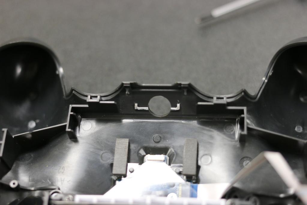
5 It is possible to remove the shell without removing either the triggers or the bumpers. The rear part near the round end of the handles should be lifted up and over the pegs that lie underneath: Once the rear handles have cleared the pegs, it is possible to push the back half of the shell forward to clear the bumper and triggers, without causing the triggers to pop off. Practice will make this process go more smoothly. If the triggers pop off, LOOK AROUND CAREFULLY FOR THE SMALL TRIGGER SPRING. The small trigger spring is required otherwise the trigger will not return fully to the non-pressed position.


6 Disassemble the circuit board Once you ve gotten the back half separated from the front half, flip it open like a clam shell: Remove the small rubber reset button as it is easy to lose. Unhook the battery wires from the battery wires hook and remove the battery.


7 The black battery holder is held in place by two plastic tabs that hook around the circuit board. The tabs can be loosened by inserting a flat-tip screwdriver in the locations shown:


8 Remove the black plastic battery holder. Remove the single screw that holds the circuit board in place. Now, remove the battery wires, remove the larger white ribbon cable by pulling straight up on the blue tab. Next, notice the smaller ribbon cable near the RESET on the board. Flip up the little white tab, then pull the ribbon cable out by pulling on the blue tab. The white tab locks the blue tab in place, so the white tab must be lifted before the blue tab can be pulled out. Once both ribbons have been removed, the battery has been removed, the reset button has been removed, and the single screw has been removed, the circuit board is still permanently

9 connected to the two rumble motors. Pull the circuit board up and flip it over clam-style again: We are now ready to proceed with modchip installation.


10 Install the modchip The modchip is installed into this location:


11 Once the solderless portion of the modchip is in place, re-install the Sony circuit board. Then put a square of electrical tape on the Sony circuit board, and fold the modchip over and stick it to the electrical tape:

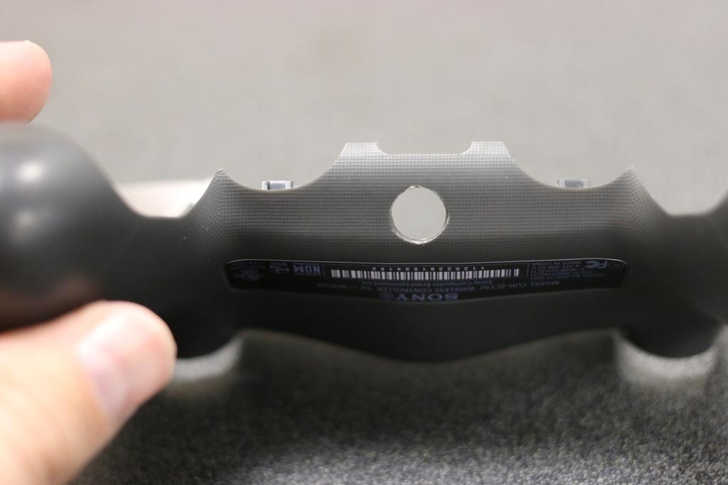
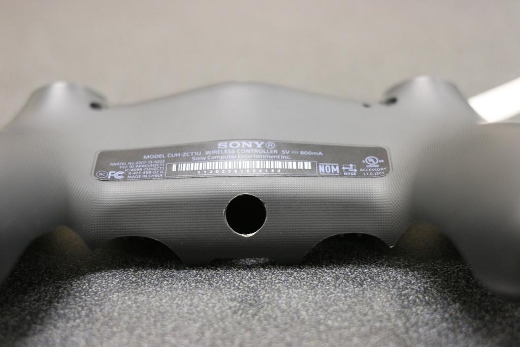
12 Drill Shell and Install Indicator Drill a 9mm hole in the shell. Practice will be required to find the best location for the hole. Also drill a smaller hole as desired for the mod switch. We recommend using a smaller drill bit to drill a guide hole, then use a larger drill bit to make the hole a little larger, and then very last use the 9mm drill bit to make the hole the correct size. The LED indicator is 9mm in diameter, and by using a 9mm drill bit, the indicator makes a nice press-fit into the hole. If you attempt to drill the shell without drilling a guide hole, you will most likely end up damaging the shell as the plastic is very soft. Remove the tab of plastic before drilling:
13
14


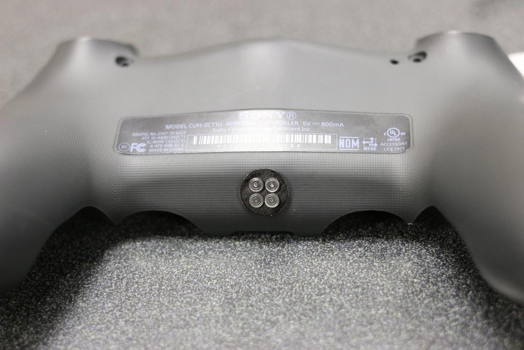
15 Press the LED lense all the way into the hole, noting the orientation of the two small nipples. The nipples will line up with the notches on the LED board. The LED board should be pressed firmly into the LED lense such that the little LED s on the board are sitting inside the LED lense. This will ensure best light performance. Be sure to keep the LED board tight and firm against the LED lense and aligned in the alignment nipples, then use a few dabs of hot glue to secure everything in place. One possible location for the mod switch is shown in the photo below:

16 Begin soldering the modchip

17 Four wires are soldered from the modchip to the Sony circuit board. LS which is the left thumbstick center button, G which is ground, V which is voltage/power, and RS which is the right thumbstick center button: Create two small wiring harnesses: one for the mod switch (2 wires), and one for the LED indicator (4 wires). In the photo below we have twisted 30 AWG wires together:

18 Install the two wires for the mod switch to both legs of the mod switch. Install the four wires for the LED board to the four pads on the LED board. The connection pairs from the modchip to the LED board are:


19 G2 goes to G V2 goes to V SCL goes to CL SDA goes to DA Please note, if you have an early version of LED board, you will need to install the two diodes in series. Both diodes can be installed together near the flex board, or you could locate one diode on the LED board as shown above. The black band on the diode should go towards the LED board and away from the main flex modchip. These diodes limit the voltage and current to the LED s. Put the controller together


20 Once the 10 wires have been installed, re-install the plastic battery cover, the ribbon cables, and the rubber reset button. The wiring harnesses you created will be routed underneath the black plastic battery holder: Route the wiring harnesses left and right into the more open areas such that they will not get pinched or caught when the shell is closed. The LED board harness can follow the ribbon cable: Test the Controller The PS4 controller can be connected to a Windows PC.


21 On Windows 7 for example, connect your controller by USB to your computer, and then type Set up USB game controllers into the search bar to launch the Windows native game controller tool. The tool can be used to check that all button presses are functioning properly. Mods such as rapidfire can be tested without the need for a console by monitoring the flashing lights in the tool:

22 Once all button presses have been confirmed working and mods have been tested, it s time to play Factory Lock/Unlock Programming The mod shop must decide which mods will be unlocked for the customer. When the mod chip is powered up for the first time, it enters a special factory programming mode. The mod chips begins by asking if basic rapidfire should be unlocked. LED1 will display a color that corresponds with the various mods that can be locked or unlocked. The lock/unlock information is programmed one-by-one with the following sequence:
23 Color Sequence RED PURPLE YELLOW BLUE GREEN PINK ORANGE BLUE RED GREEN WHITE YELLOW AQUA/LIGHT BLUE PINK WHITE Mod Rapid fire Dual-trigger Rapid Fire Jitter Akimbo Rapidfire Burst Rapidfire Hybrid Optic Rapidfire (currently unavailable) Dropshot/Jumpshot Fast Reload Quick Scope Sniper Breath Hold Zombie auto aim Auto Spot Auto Sprint Turbo Melee Selectable Button Layouts To unlock a mod, press the TRIANGLE button. LED4 will flash green to indicate that it accepted your input and unlocked the mod. To lock a mod, press the EX button. LED4 will flash red to indicated that it accepted your input and locked the mod. If at any time you realize you have entered an incorrect lock/unlock, you may press the mod switch to start over again at the beginning. Once the final mod on the list has been locked/ unlocked, the changes become permanent and cannot be changed.
Installation tutorial for Console Customs PS3 TrueFire Standard Rapid fire Microchip for Sixaxis and Dualshock 3 controllers
 Installation tutorial for Console Customs PS3 TrueFire Standard Rapid fire Microchip for Sixaxis and Dualshock 3 controllers This tutorial is designed to aid you in installation of a console customs rapid
Installation tutorial for Console Customs Xbox 360 Dual Rapid fire Microchip for wired and wireless controllers (all versions)
") Installation tutorial for Console Customs Xbox 360 Dual Rapid fire Microchip for wired and wireless controllers (all versions) This tutorial is designed to aid you in installation of a console customs
Installation tutorial for Console Customs Xbox 360 Dual Rapid fire Microchip for wired and wireless controllers (all versions) This tutorial is designed to aid you in installation of a console customs
INSTALLATION INSTRUCTIONS
 XMOD 23 Mode Rapid Fire Mod Chip INSTALLATION INSTRUCTIONS This tutorial is designed to aid you in the installation of a XMOD Rapid Fire microchip. This installation requires soldering several wires to
Ragnarok PS4 Flex Mod Chip Operation Instructions
 www.viking360.com Introduction The Viking Ragnarok software platform was developed to make it easier for customers to mix and match mods, on the fly, without needing to scroll through massive numbers of
Installation tutorial for Console Customs Xbox 360 MaxFire LITE rapid fire Mod Chip.
 Installation tutorial for Console Customs Xbox 360 MaxFire LITE rapid fire Mod Chip. This tutorial is designed to aid you in installation of a console customs MaxFire LITE modchip. This tutorial covers
Installation tutorial for Console Customs Xbox Mode Dual Button (RFX-5B) Rapid fire Microchip for all Wired and Wireless controllers
 Rapid fire Microchip for all Wired and Wireless controllers") Installation tutorial for Console Customs Xbox 360 5-Mode Dual Button (RFX-5B) Rapid fire Microchip for all Wired and Wireless controllers This tutorial is designed to aid you in installation of a console
Installation tutorial for Console Customs Xbox 360 5-Mode Dual Button (RFX-5B) Rapid fire Microchip for all Wired and Wireless controllers This tutorial is designed to aid you in installation of a console
Installation tutorial for Console Customs Xbox ONE MaxFire ONE V2 PCB
 Installation tutorial for Console Customs Xbox ONE MaxFire ONE V2 PCB This tutorial is designed to aid you in installation of a console customs MaxFire ONE V2 Circuit board in the newer Xbox One Controllers
XMOD RAPID FIRE MOD KIT 20 MODES - v4 INSTRUCTIONS
 v4 ELECTRONICS XMOD RAPID FIRE MOD KIT 20 MODES - v4 INSTRUCTIONS This tutorial is designed to aid you in the installation of a XMOD Rapid Fire microchip. This installation requires soldering several wires
Team Xecuter Joycon Mod By: XxWiReDxX
 Team Xecuter Joycon Mod By: XxWiReDxX Works With Every Switch SX OS Works with every Nintendo Switch and every firmware version! Play Every Game With SX OS you can play all your favorite games straight
XMOD 18 Mode Rapid Fire Mod Chip
 XMOD 18 Mode Rapid Fire Mod Chip INSTALLATION INSTRUCTIONS - PCB version 2 This tutorial is designed to aid you in the installation of a Rapid Fire microchip. This installation requires soldering several
Harmony Remote Repair
 Harmony Remote Repair harmonyremoterepair.com How to install your new Harmony One Front Cover/Touch Screen Important! Before you begin working on your Harmony One, you must discharge any static electricity
DIY Instructions For NGPC Front Light Installation using the Gameboy Advanced SP Front Light
 DIY Instructions For NGPC Front Light Installation using the Gameboy Advanced SP Front Light Tools you will need: Phillips Screwdriver Flat head Screwdriver Tri-wing Screwdriver Exacto Knife Soldering
Repairing Microsoft Wedge Touch Mouse Battery Cover Retaining Clip
 Repairing Microsoft Wedge Touch Mouse Battery Cover Retaining Clip Disassembly, repair and reassembly of Wedge Touch mouse when the battery cover will not stay closed. Also is a good guide to repair other
AUDI A8 D3 REPLACING THE OUTSIDE DRIVER DOOR HANDLE
 AUDI A8 D3 REPLACING THE OUTSIDE DRIVER DOOR HANDLE The keyless entry system in the D3 is a great feature. If you have the car key fob in your pocket, putting your hand under the door handle will unlock
LED Cup Holder Lights Installation Guide
 LED Cup Holder Lights Installation Guide (20112015 Kia Optima) Thanks for purchasing this LED Cup Holder Light Kit! If you have any questions or feedback please email us direct at Sales@K5OptimaStore.com
Written By: Adam O'Camb
 iphone XR Display Assembly Replacement Replace a cracked or faulty LCD screen in your iphone XR. Written By: Adam O'Camb ifixit CC BY-NC-SA www.ifixit.com Page 1 of 23 INTRODUCTION If your iphone XR screen
STRIKEPACK F.P.S. DOMINATOR MODE UPGRADE
 STRIKEPACK F.P.S. DOMINATOR MODE UPGRADE Once your StrikePack has received the Dominator upgrade, you can refer to the rest of this document for operation instructions. UPGRADING THE STRIKEPACK Open the
Iphone 5 Glass/Lcd REPAIR GUIDE. Version Edition
 Iphone 5 Glass/Lcd REPAIR GUIDE Version 1 2016 Edition IPhone 5 Glass/LCd REPAIR GUIDE RiAna Soto Repair Training Specialist rsoto@cellairis.com FOR EVERY REPAIR MAKE SURE TO COMPLETE, INITIAL, AND HAVE
INSTRUCTION MANUAL PS4 JUGGERNAUT VER 7.0
 INSTRUCTION MANUAL PS4 JUGGERNAUT VER 7.0 Congratulations, welcome to the GamerModz Family! You are now a proud owner of a GamerModz Custom Modded Controller. The JUGGERNAUT - VER 7.0 FOR PS4 has been
Written By: Brett Hartt
 Replace the battery in your ipad 3 4G. Written By: Brett Hartt ifixit CC BY-NC-SA www.ifixit.com Page 1 of 36 INTRODUCTION When your ipad can't stay awake for longer than a few hours, it is time to replace
Written By: Walter Galan
 iphone 4S Logic Board Replacement Replace a dead logic board in your iphone 4S. Written By: Walter Galan ifixit CC BY-NC-SA www.ifixit.com Page 1 of 22 INTRODUCTION Use this guide to replace your iphone's
iphone 4S Dismantling Instructions
 iphone 4S Dismantling Instructions These instructions will show you how to open the iphone to replace the digitizer, LCD screen and other internal parts. Opening your iphone will void your warrantee, and
2011 KIA Optima SX / EX Turbo Mesh Grille
 IMPORTANT: PLEASE KEEP THIS INSTRUCTION MANUAL FOR FUTURE REFERENCE! TOOLS REQUIRED 2011 KIA Optima SX / EX Turbo Mesh Grille Upper and Lower Overlay Part #: Complete 1310-0102-11SX / Black Ice Part #1310-B102-11SX
Written By: Walter Galan
 ipad 4 CDMA SIM Board Replacement Replace the SIM Board in your ipad 4 CDMA. Written By: Walter Galan ifixit CC BY-NC-SA www.ifixit.com Page 1 of 33 INTRODUCTION Use this guide to replace the SIM Board.
Arsenal One Install Instructions for Xbox One Controller
 Arsenal One Install Instructions for Xbox One Controller arsenalmod.com Page 1 of 14 Before Proceeding These instructions are for the install of the Arsenal One 28 pin chip for the Xbox One. READ ALL INSTRUCTIONS
ipad 2 GSM Right Cellular Data Antenna Replacement
 ipad 2 GSM Right Cellular Data Antenna Replacement Replace the right cellular data antenna in your ipad 2 GSM. Written By: Brett Hartt ifixit CC BY-NC-SA www.ifixit.com Page 1 of 43 INTRODUCTION Use this
7878 K940. Checkpoint Antenna. Kit Instructions. Issue B
 7878 K940 Checkpoint Antenna Kit Instructions Issue B Revision Record Issue Date Remarks A July 7, 2009 First issue B Nov2013 Revised the Checkpoint installation procedures for 7878 and 7874 scanners Added
Written By: Evan Noronha
 Replace the logic board in an ipad Air LTE. Written By: Evan Noronha ifixit CC BY-NC-SA www.ifixit.com Page 1 of 50 INTRODUCTION Follow the steps in this guide to replace the logic board in an ipad Air
Written By: Walter Galan
 Replace the small antenna attached to the headphone jack of your iphone 4S. Written By: Walter Galan ifixit CC BY-NC-SA www.ifixit.com Page 1 of 23 INTRODUCTION Use this guide to replace your iphone's
FlexRC Mini Owl - Extreme FPV Proximity Racing Drone - DIY Build Instructions
 FlexRC Mini Owl - Extreme FPV Proximity Racing Drone - DIY Build Instructions This guide will walk you through the detailed build steps using the FlexRC Mini Owl Extreme FPV Racing Drone DIY Kit. The kit
OpenROV. Guide 3 - Electronics. We will now move to the assembly of the electronics that will control the ROV. Written By: OpenROV
 OpenROV Guide 3 - Electronics We will now move to the assembly of the electronics that will control the ROV. Written By: OpenROV 2017 openrov.dozuki.com Page 1 of 33 INTRODUCTION We will introduce soldering
ipad 3 4G Home Button Control Board Replacement
 ipad 3 4G Home Button Control Board Replacement Replace the home button control board in your ipad 3. Written By: Brett Hartt ifixit CC BY-NC-SA www.ifixit.com Page 1 of 28 INTRODUCTION This guide will
Cover Page. Factory Radio Other Documents Available For This Vehicle:
 Factory Radio Other Documents Available For This Vehicle: No documents available at this time Adobe Acrobat Reader Printing Tips: 1) Select FLE then PRNT and select your printer. 2) n the print options
Asus ZenFone 2 Display Replacement
 Asus ZenFone 2 Display Replacement Replace your display if it isn't functioning correctly or if it is cracked or broken. Written By: Jessica Nguyen ifixit CC BY-NC-SA www.ifixit.com Page 1 of 14 INTRODUCTION
Written By: Brett Hartt
 Replacing the Wi-Fi antenna in the third generation ipad Written By: Brett Hartt ifixit CC BY-NC-SA www.ifixit.com Page 1 of 31 INTRODUCTION Wireless internet is awesome. A third generation ipad without
Removing and Replacing the Y-truck
 Service Documentation Removing and Replacing the Y-truck To remove and replace the Y-truck you will need the following tools: 4mm Allen wrench 12mm stamped flat wrench #2 Phillips screwdriver (magnetic
Written By: Walter Galan
 Replace the Logic Board in your ipad 4 Wi-Fi. Written By: Walter Galan ifixit CC BY-NC-SA www.ifixit.com Page 1 of 32 INTRODUCTION Use this guide to replace the logic board. TOOLS: iopener (1) Phillips
ipad 3 4G Home Button Assembly Replacement
 ipad 3 4G Home Button Assembly Replacement Replace the home button assembly in your ipad 3 4G. Written By: Brett Hartt ifixit CC BY-NC-SA www.ifixit.com Page 1 of 29 INTRODUCTION Use this guide to replace
Explorer Wiring Kit (assembled)
") Explorer Wiring Kit (assembled) For Vintage, Firestorm & Standard Series Please Read All Instructions Before Beginning. Tools you will need: Soldering Iron (35 watt preferably) Solder Wet Sponge Wire Clippers
Explorer Wiring Kit (assembled) For Vintage, Firestorm & Standard Series Please Read All Instructions Before Beginning. Tools you will need: Soldering Iron (35 watt preferably) Solder Wet Sponge Wire Clippers
Written By: Walter Galan
 ipad 3 Wi-Fi Dock Connector Replacement Replace the dock connector in your ipad 3 Wi-Fi. Written By: Walter Galan ifixit CC BY-NC-SA www.ifixit.com Page 1 of 29 INTRODUCTION Use this guide to replace the
Telecaster Wiring Kits Please Read All Instructions Before Beginning. Tools you will need: Soldering tips: Removing Current Wiring: Step 1. Step 2.
 Telecaster Wiring Kits Please Read All Instructions Before Beginning. Tools you will need: Soldering Iron (35 watt preferably) Solder Wet Sponge Wire Clippers Wire Strippers 3/8 Drill Bit 5/32 Drill Bit
or + Akimbo (Dual Trigger Rapid Fire)
") Page 1: Introduction, Feature access Page 2: Rapid Fire, Burst Fire, Akimbo, Mimic Page 3: Default Modes, Changing Modes, Adjustable Fast Reload Page 4: Sub Modes, Drop Shot, Jump Shot, Automatic Sniper
Page 1: Introduction, Feature access Page 2: Rapid Fire, Burst Fire, Akimbo, Mimic Page 3: Default Modes, Changing Modes, Adjustable Fast Reload Page 4: Sub Modes, Drop Shot, Jump Shot, Automatic Sniper
FitWork Walkstation Series 7 AdjusTables
 FitWork Walkstation Tools Required: #2 Phillips Bit with Extension Page 1 of 20 A7TG660606H A7TR663232H FitWork Walkstation 4mm Hex Head Bit A7TG660632H A7TR383030H www.details-worktools.com A7TG663206H
Written By: Walter Galan
 Replace the logic board in your ipad 3 Wi-Fi. Written By: Walter Galan ifixit CC BY-NC-SA www.ifixit.com Page 1 of 29 INTRODUCTION Use this guide to replace the logic board. TOOLS: iopener (1) Phillips
CABINETRY Assembly Instructions
 www.hdicabinetry.com Assembly Instructions TABLE OF CONTENTS Category Page(s) Section 1: Framed Series Base Cabinet Instructions Wall Cabinet Instructions Easy Reach Cabinet Instructions 1.01-1.04 1.05-1.06
Written By: Ben Eisenman
 iphone 3GS Front Panel Replacement Replace a cracked front panel on an iphone 3GS. Written By: Ben Eisenman ifixit CC BY-NC-SA www.ifixit.com Page 1 of 18 INTRODUCTION Use this guide to separate and replace
ABM International, Inc. Navigator Assembly Manual
 ABM International, Inc. 1 1.0: Parts List Tablet (Qty. 1) Tablet mount (Qty. 1) NOTE: Mount may appear and operate different then image below Control Box (Qty. 1) Motor Power Supply (Qty. 1) 2 X-axis motor
Repairing iphone 4 LCD Backlight Dim spot issue
 Repairing iphone 4 LCD Backlight Dim spot issue found a way to fix a liquid damaged iphone screen back light issue Written By: Pranav Singh ifixit CC BY-NC-SA www.ifixit.com Page 1 of 26 INTRODUCTION found
ZROADZ Grille series - LED Installation Guide
 ZROADZ Grille series - LED Installation Guide START HERE The ZROADZ Series Grilles comes into 2 different configurations. One style features the LED Light Bar mounting hidden on the backside, while the
IMPORTANT: WILL NOT FIT COUNTRYMAN MODELS
 Part #1410-0102-07 2 3 1 IMPORTANT: WILL NOT FIT COUNTRYMAN MODELS Apply masking tape around the bottom grille opening and across the bottom of the upper facto ry grille.. Open the hood and remove the
Written By: Sam Lionheart
 Replace the SIM Board in your ipad 4 GSM. Written By: Sam Lionheart ifixit CC BY-NC-SA www.ifixit.com Page 1 of 29 INTRODUCTION Use this guide to replace the SIM Board. TOOLS: SIM Card Eject Tool (1) iopener
Ribcage Installation. Part 2 - Assembly. Back-Bone V1.06
 Ribcage Installation Part 2 - Assembly Back-Bone V1.06 Contents Section 1 Before You Get Started... 2 Included With Your Kit:... 2 Figure: A... 3 CAUTION!... 4 Note:... 4 Tools Required... 5 Section 2:
Instructions for Lighting an S Scale Caboose
 Instructions for Lighting an S Scale Caboose The S Scale Caboose lighting kit is adaptable for most caboose models of rolling stock including American Flyer (TM) and contains the same components as found
CONTENTS. Akimbo (Left Trigger Rapid Fire)
") CONTENTS Page 1: Introduction, Feature access Page 2: Rapid Fire, Burst Fire, Akimbo, Mimic Page 3: Default Modes, Changing Modes, Adjustable Fast Reload Page 4: Sub Modes, Drop Shot, Jump Shot, Automatic
CONTENTS Page 1: Introduction, Feature access Page 2: Rapid Fire, Burst Fire, Akimbo, Mimic Page 3: Default Modes, Changing Modes, Adjustable Fast Reload Page 4: Sub Modes, Drop Shot, Jump Shot, Automatic
BABY WOLF LOOM. Assembly Instructions for Knocked-Down Looms
 BABY WOLF LOOM Assembly Instructions for Knocked-Down Looms BEFORE YOU BEGIN Please read through the directions before beginning to assemble your loom. Unpack the loom parts carefully. Do not throw away
The Useless Machine. DIY Soldering Edition. Instruction Guide v0004
 The Useless Machine DIY Soldering Edition Instruction Guide v0004 TM For the best outcome, follow each step in order. We recommend reading this guide entirely before you get started. Tools required: Soldering
Circuit Board Assembly Instructions for Babuinobot 1.0
 Circuit Board Assembly Instructions for Babuinobot 1.0 Brett Nelson January 2010 1 Features Sensor4 input Sensor3 input Sensor2 input 5v power bus Sensor1 input Do not exceed 5v Ground power bus Programming
To maximize your potential, be sure to read the instructions fully before operating the Mega Mod.
 You are now the proud owner of our exclusive Mega Mod! The Mega Mod is our ultimate modded controller and features all of the mods that we offer for the PlayStation 3. The Mega Mod comes with 9 different
Written By: Brett Hartt
 ipad 3 4G LCD Replacement Removing the LCD Written By: Brett Hartt ifixit CC BY-NC-SA www.ifixit.com Page 1 of 25 INTRODUCTION The third generation ipad loses a lot of luster when its gorgeous retina display
Tin Lizzie 18 Assembly Instructions
 Tin Lizzie 18 Assembly Instructions Revision: 07/29/16 Table of Contents Aides 3 Before You Begin 5 Aides 5 Tools 6 Perfect Stitch Parts 2 12 Modify the Machine 12 Prepare Drill Templates 12 Front Display
WARNING: Prior to installation, turn the power off to the vending machine and unplug it from its power source. Also, make sure to level the machine.
 Installation of Gum and Mint Tray for National 147, 157, 167 Important Note: Please read all instructions thoroughly before continuing with installation of kit. If you are having problems installing the
unit 3: GENErAL ElectriCAL SySTEM DiAGNOSiS
 Electrical/Electronic Systems unit 3: GENErAL ElectriCAL SySTEM DiAGNOSiS lesson 4: wire and connector repairs I. Connector repairs A. Connector repairs involve fixing damaged wires. Wires are marred due
Written By: Andrew Optimus Goldberg
 Replace the screen your GSM/AT&T iphone 4. Written By: Andrew Optimus Goldberg ifixit CC BY-NC-SA www.ifixit.com Page 1 of 25 INTRODUCTION [video: http://www.youtube.com/watch?v=obpfpfx5abw] Use this guide
3 Shielded Compact Ribbon (SCR) Wiremount Plug, XX, and Shell Kit, F200-XXX
 Wiremount Plug, XX, and Shell Kit, F200-XXX") 3 Shielded Compact Ribbon (SCR) Wiremount Plug, 36110-3000XX, and Shell Kit, 36310-F200-XXX Instructions June 2007 78-9100-4282-5 General This instruction manual explains the method of assembling the 3M
3 Shielded Compact Ribbon (SCR) Wiremount Plug, 36110-3000XX, and Shell Kit, 36310-F200-XXX Instructions June 2007 78-9100-4282-5 General This instruction manual explains the method of assembling the 3M
Hardware Installation. Do this first:
 1 Do this first: Hardware Installation Need some help? Here s what you ll need: 4 AA Batteries Phillips screwdriver Visit us online. support.remotelock.com We re here to help. 1 (877) 254 5625 support@remotelock.com
======================================================================================== ( DR / DR) JK WRANGLER MOD RACK
 JK WRANGLER MOD RACK") (10984 4DR / 10982 2DR) JK WRANGLER MOD RACK INSTALLATION SHEET Important Notes: Some brands of windshield light brackets and snorkels may not be compatible with the 10984 MOD Rack System. Body lifts are
(10984 4DR / 10982 2DR) JK WRANGLER MOD RACK INSTALLATION SHEET Important Notes: Some brands of windshield light brackets and snorkels may not be compatible with the 10984 MOD Rack System. Body lifts are
Installation Instructions
 by Plato Woodwork Installation Instructions Plato Woodwork, Inc. 200 Third Street SW P.O. Box 98 Plato, MN 55370 www.platowoodwork.com 800.328.5924 SECTION GUIDE GETTING STARTED PAGE # Installation Methods...
Installation instructions, accessories. TV receiver, digital
 Installation instructions, accessories Instruction No 30756561 Version 1.1 5 Part. No. 30756181, 30756569 TV receiver, digital Volvo Car Corporation TV receiver, digital- 30756561 - V1.1 Page 1 / 36 Equipment
Written By: Jeff Suovanen
 iphone XS Max Lower Speaker Replacement Remove or replace the main loudspeaker on the bottom edge of the iphone XS Max. Written By: Jeff Suovanen ifixit CC BY-NC-SA www.ifixit.com Page 1 of 23 INTRODUCTION
Celerity Fiber Termination Kit
 Celerity Fiber Termination Kit User Guide Product Overview The Celerity Fiber Termination Kit (CT-FTK) is a professional tool set for splicing and terminating fiber optic cables in the field or at an assembly
iphone 6 Chargeport REPAIR GUIDE Version Edition
 iphone 6 Chargeport REPAIR GUIDE Version 1 2016 Edition IPHONE 6 CHARGEPORT REPAIR GUIDE LCD AND DIGITIZER REPLACEMENT RiAna Soto Repair Training Specialist rsoto@cellairis.com FOR EVERY REPAIR MAKE SURE
DC Motor. Controller. User Guide V0210
 DC Motor Controller User Guide 59757 V0210 This kit provides a great exercise of intermediate soldering skills and creates a device that enables you to control various Pitsco motors, Tamiya gearboxes,
Build your own. Stages 7-10: See Robi s head move for the first time
 Build your own Pack 03 Stages 7-10: See Robi s head move for the first time Build your own All rights reserved 2015 Published in the UK by De Agostini UK Ltd, Battersea Studios 2, 82 Silverthorne Road,
Shepherd 210A Fingerprint Door Lock Installation Manual V1.1
 Shepherd 210A Fingerprint Door Lock Installation Manual V1.1 Hongda USA Inc. 2505 Technology Dr. #2-6A, Hayward, CA 94545, USA Phone: (510) 887-5682 Fax: (510) 372-0487 Email: info@hongdausa.com Website:
Heartboard PCB Assembly Instructions
 Heartboard PCB Assembly Instructions Thanks for purchasing a Heartboard! These instructions will guide you through assembling and testing the Heartboard. Let s get started! Stuff you need Soldering iron
Signal Mirror Installation Instructions Toyota Tacoma
 Signal Mirror Installation Instructions 2005-2015 Toyota Tacoma THE safety accessory of the 21 st Century. P/N 210-0115-0 Rev. A4 (3/11/15), BTV 2005 Muth Mirror Systems, LLC Page 3 of 12PplPage 3 of 12
Service Manual for XLE/XLT Series Laser Engravers
 Service Manual for XLE/XLT Series Laser Engravers Table of Contents Maintenance...1 Beam alignment...3 Auto focus alignment...8 Bridge alignment...10 Electronics panel replacement...11 X motor change...12
Instructions to Convert a 4-foot Florescent Fixture to LEDs Using 100W Power Supply Using 1-4 strips 30Dec15
 Instructions to Convert a 4-foot Florescent Fixture to LEDs Using 100W Power Supply Using 1-4 strips 30Dec15 Thank you for purchasing the Shoplight Solutions 100W conversion kit. This is a companion document
Elektor Construction Guide TAPIR
 Elektor Construction Guide TAPIR The TAPIR is a three-dimensional assembly. To ensure good access to all soldering points, we recommend assembling the kit exactly according to the described sequence. 1
Plug-n-Show Stake Down Pixel Tree Kit 16 strips of 25 pixels Assembly Instructions
 www.lightorama.com Plug-n-Show Stake Down Pixel Tree Kit 16 strips of 25 pixels Assembly Instructions Read all instructions before you start Kit assembly! STEP 1. Check that all parts are included Parts
Mac mini Model A1283 RAM Replacement
 Mac mini Model A1283 RAM Replacement Written By: Walter Galan ifixit CC BY-NC-SA www.ifixit.com Page 1 of 10 INTRODUCTION Accessing the RAM requires the removal of the internal frame. TOOLS: Jimmy (1)
Written By: Walter Galan
 Xbox 360 CPU Heat Sink Replacement CPU heat sink replacement. Written By: Walter Galan ifixit CC BY-NC-SA www.ifixit.com Page 1 of 27 INTRODUCTION Use this guide to remove the CPU heat sink from your Xbox
Vinyl Cutter Instruction Manual
 Vinyl Cutter Instruction Manual 1 Product Inventory Inventory Here is a list of items you will receive with your vinyl cutter: Product components (Fig.1-4): 1x Cutter head unit complete with motor, plastic
ABM International, Inc.
 ABM International, Inc. Lightning Stitch required 1 1.0: Parts List head and motor assembly (Qty. 1) Reel stand (Qty. 1) Needle bar frame clamp (Qty. 1) Motor drive (Qty. 1) 2 Cable harness with bracket
Congratulations on purchasing the Spirit Rails Magnetic Attach that allows easy wand to pack removal and reattachment by just getting close!
 Introduction Congratulations on purchasing the Spirit Rails Magnetic Attach that allows easy wand to pack removal and reattachment by just getting close! The Spirit Rails Magnetic Attach Kit is designed
CONTENTS. or + Akimbo (Left Trigger Rapid Fire)
") CONTENTS Page 1: Introduction, Feature access Page 2: Rapid Fire, Burst Fire, Akimbo, Mimic Page 3: Default Modes, Changing Modes, Adjustable Fast Reload Page 4: Sub Modes, Drop Shot, Jump Shot, Automatic
CONTENTS Page 1: Introduction, Feature access Page 2: Rapid Fire, Burst Fire, Akimbo, Mimic Page 3: Default Modes, Changing Modes, Adjustable Fast Reload Page 4: Sub Modes, Drop Shot, Jump Shot, Automatic
DO NOT PULL ON THE SHEATH.
 Removing and Replacing the Head Cover To remove and replace the head cover you will need the following tools: #2 Phillips screwdriver (magnetic tip preferred) Removing the Head Cover 1. Ready the machine
PS4 FOR STRIKEPACK F.P.S. DOMINATOR WIRED NEXT GENERATION MOD PACK
 FOR PS4 STRIKEPACK F.P.S. DOMINATOR WIRED NEXT GENERATION MOD PACK Introduction 3 Getting started - Attaching the StrikePack F.P.S. Dominator 4 - Pairing the StrikePack F.P.S. Dominator with Your Console
Custom Front Panel Upgrade Instructions
 Custom Front Panel Upgrade Instructions Here are the directions for upgrading your SP-II to an SP-IIB, with a custom blackanodized front panel and engraved lettering. There are only forty SP-IIB s in existence
Bushwacker Jeep Flat Style Fender Flares Front Pair
 Bushwacker Jeep Flat Style Fender Flares Front Pair Note: These instructions involve cutting parts of your vehicle. Please read all instructions prior to starting. Installation Time: 3-4 Hours Tools Required:
Instructions to Convert a 4-foot Florescent Fixture to LEDs Using 60W Power Supply Using 2 or 3 strips 30Dec15
 Instructions to Convert a 4-foot Florescent Fixture to LEDs Using 60W Power Supply Using 2 or 3 strips 30Dec15 Thank you for purchasing the Shoplight Solutions 4-ft conversion kit. This is a companion
Bi-Color Signal Mirror Installation Instructions
 Bi-Color Signal Mirror Installation Instructions 2005-2009 Toyota Tacoma THE safety accessory of the 21 st Century. P/N 210-0141-0 Rev. A2 (3/30/09), BTV 2007 Muth Mirror Systems, LLC Page 3 of 13PplPage
Solio Xcellerator and Hub Battery Pack Solar Panel Replacement
 Solio Xcellerator and Hub Battery Pack Solar Panel Replacement This guide covers the replacement of an unusable solar panel. Written By: Brian Sukkar ifixit CC BY-NC-SA www.ifixit.com Page 1 of 10 INTRODUCTION
Rocketry Challenge - Technical Document I
 Rocketry Challenge - Technical Document I This document includes a list of what is inside the kit with pictures for hard to decipher parts and a simple step-by-step process of how to assemble and launch
Nikon D70 Eyepiece Replacement
 Replace the Eyepiece in your Nikon D70. Rédigé par: Andrew Bookholt ifixit CC BY-NC-SA fr.ifixit.com Page 1 de 21 INTRODUCTION Use this guide to replace the eyepiece cover that allows for focus compensation.
2.007 Design and Manufacturing I
 MIT OpenCourseWare http://ocw.mit.edu 2.007 Design and Manufacturing I Spring 2009 For information about citing these materials or our Terms of Use, visit: http://ocw.mit.edu/terms. Fabrication of a Simple
Xbox One / PS4 Guide. Xbox One Quick Guide. PlayStaJon 4 Quick Guide MODE SPEED COMPATIBLE GAMES MODE SPEED COMPATIBLE GAMES
 Xbox One / PS4 Guide This guide will cover all aspects of your Xbox One PlayStation 4 controller. Please read all parts of this guide befe setting up and using your Xbox One PlayStation 4 controller. Please
I Click on a link tab to jump to that page. Cover Page
 Factory Radio Other Documents Available For This Vehicle: No documents available at this time Adobe Acrobat Reader Printing Tips: 1) Select FLE then PRNT and select your printer. 2) n the print options
GETTING STARTED. Instructions IMPORTANT PS B PS B. Record the serial number from the tag on the door front.
 PS-15-20-B IMPORTANT Instructions Record the serial number from the tag on the door front. Keep keys in a secure place away from children. DO NOT STORE KEYS INSIDE SAFE GETTING STARTED When you first receive
4. Partially open the operating panel and tilt the top toward the interior of the door (Figure 4). Lift the panel off the sill and set it aside.
. Lift the panel off the sill and set it aside.") Effective Date: 10/1/2017 Tools Needed Kit Contents Hardware Kit Safety Glasses Cordless drill Phillips screw bit Two-step drill bit (3/8-1/8 ) utility knife Interior Mullion Exterior Mullion Cover clamps
Effective Date: 10/1/2017 Tools Needed Kit Contents Hardware Kit Safety Glasses Cordless drill Phillips screw bit Two-step drill bit (3/8-1/8 ) utility knife Interior Mullion Exterior Mullion Cover clamps