INSTALLATION INSTRUCTIONS
|
|
|
- Regina Perkins
- 5 years ago
- Views:
Transcription


1 XMOD 23 Mode Rapid Fire Mod Chip INSTALLATION INSTRUCTIONS This tutorial is designed to aid you in the installation of a XMOD Rapid Fire microchip. This installation requires soldering several wires to small confined spaces. We do not advise attempting this installation if you are a beginner at soldering. We recommend reading through all the instructions and understanding them before beginning your installation. Disclaimer: Undertaking this modification is done at your OWN risk, XMOD ELECTRONICS does NOT take any responsibility to any damage caused to your controller, your console, nor yourself or any equipment. We will NOT replace broken controllers, which you have damaged following the guide; you disassembled the controller at your own risk. We will NOT replace kits which have been damaged during their installation process, although we will try to help you the best we can, just ask. If you are struggling or have any problems, get in touch with us before go any further, we are here to help. We only recommend doing this modification if you are experienced with electronics and using a soldering iron. Tools Needed Soldering Iron with rosin core solder. Hot Glue gun with glue sticks. Wire cutters and wire strippers (that can strip 30ga wire). 5/32 drill bit Torx T8 Security screwdriver (You may also use a 2.0 precision flathead screwdriver if you can t find a security torx screwdriver). TORX SCREW T8 XMOD Rapid Fire MOD CHIP TACTILE SWITCH MOD CHIP COMPATIBLE BOARDS: This XMOD CHIP will work with CG/CG2 XBOX 360 Wireless Controller Boards only. It s not compatible with MATRIX 1-2 Boards.


2 Remove the (7) security screws with the T8 security screwdriver. Keep the controller upside down and remove the back of the controller shell. Take the board out of the other half of the shell and place the front half of the shell to the side. Place the controller board right side up.


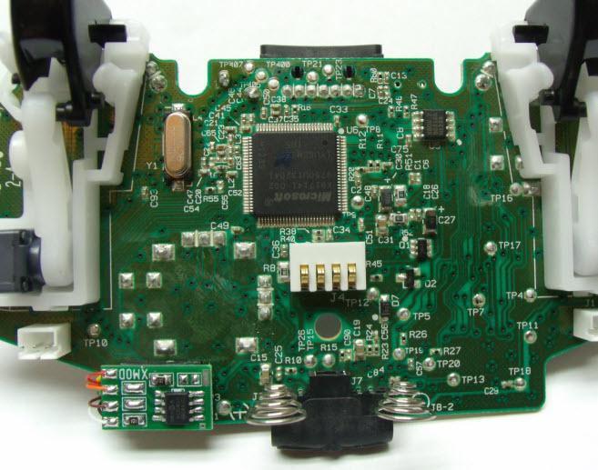
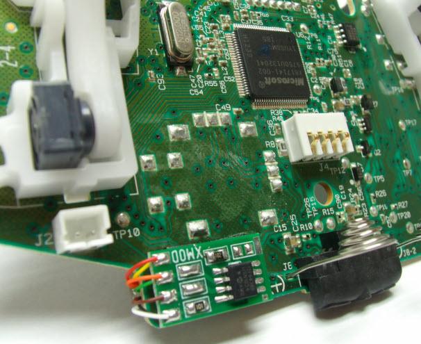
3 Wireless Controller Identification With the back cover removed it is easy to identify the old and the new style controllers. See the images below. In the NEW style-cg Controller, you will see a single chip rotated 45 degrees NEW STYLE - CG In the NEW style-cg2 Controller, you will see a single chip. NEW STYLE - CG2 In the old style controller There are two chips. Some controllers will not Have the silver shield over the larger chip. OLD STYLE MATRIX


4 ELECTRONICS NEW CG NEW CG WIRELESS BOARD From the battery door area you can see the CAPACITOR is horizontally oriented. ELECTRONICS NEW CG2 NEW CG2 WIRELESS BOARD From the battery door area you can see the CAPACITOR is vertically oriented. ELECTRONICS OLD MATRIX OLD MATRIX-1 WIRELESS BOARD From the battery door area you can see that there is NO CAPACITOR on the left side, while the other two versions do have a capacitor. NOT COMPATIBLE XELECTRONICS xmod electronics MATRIX-2 WIRELESS BOARD From the battery door area you can see that there is NO CAPACITOR NOT COMPATIBLE

, you")

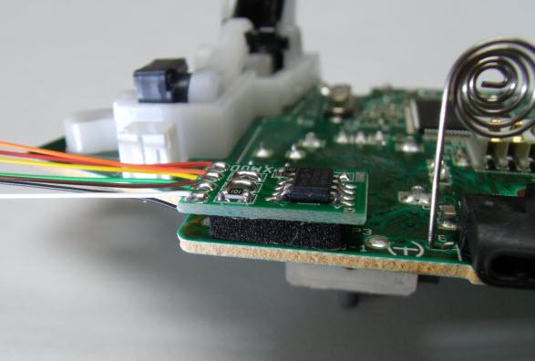
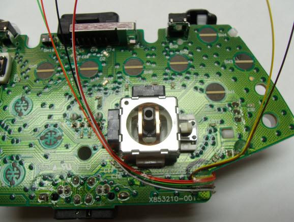
5 After checking the mod chip for your XBOX motherboard version (CG-CG2), you can use the double sided tape to attach both boards.
6
7


8 Trim your wires so they are only as long as you need, then strip the end to solder into place. Long wires will just cause a place for something to snag when closing the controller. Strip the wires no more than 2-3 mm. Exposing bare wire beyond solder connections could cause a short if the bare wire touches something it shouldn t. Make sure to keep exposed wires that have had insulation removed as close to the solder connection as possible minimizing the chance of a short circuit.


9 MOD CHIP PC BOARD 23 MODE XMOD B D G C POSITIVE SYNC - MODE B -BUTTON LED NEGATIVE A F E LEFT TRIGGER RIGHT TRIGGER
10
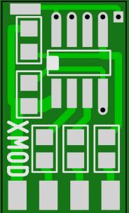
11 XMOD


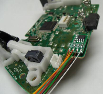
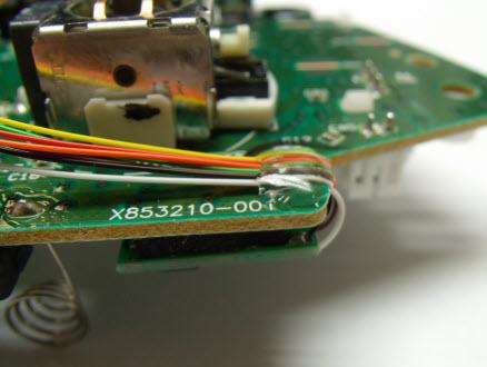
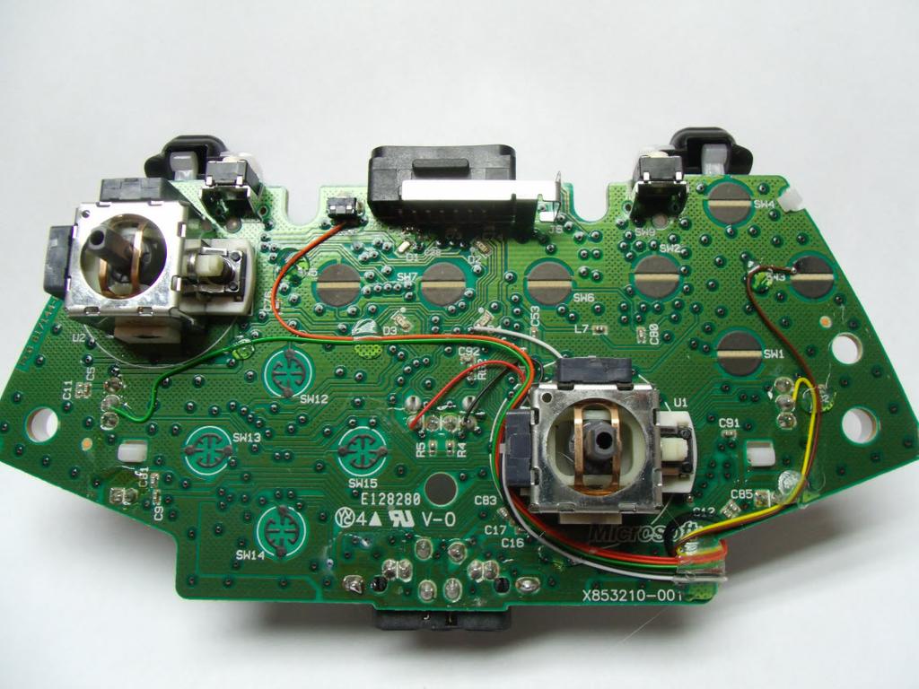
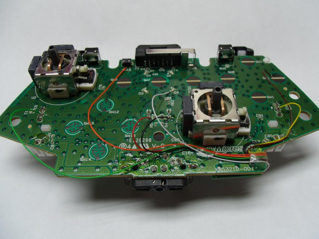
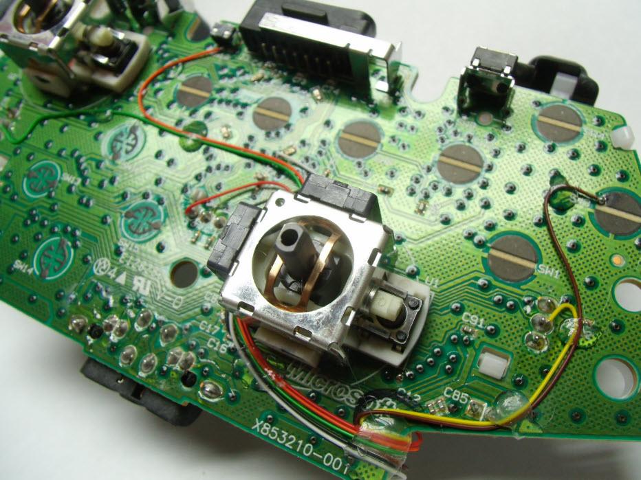
12 Solder the wires as shown in the images BLACK & RED wires (Positive & Negative)


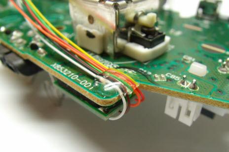
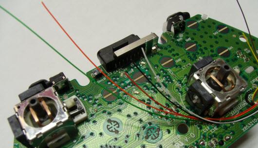
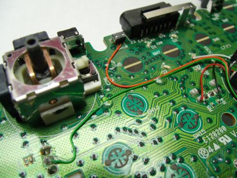
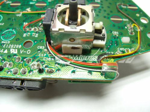
13 YELLOW wire (Right Trigger) GREEN wire (LeftTrigger)


 and the solder should flow onto the pad.")

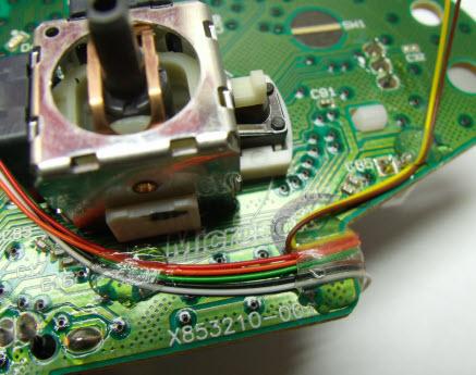
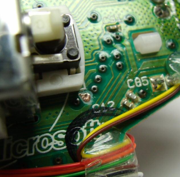
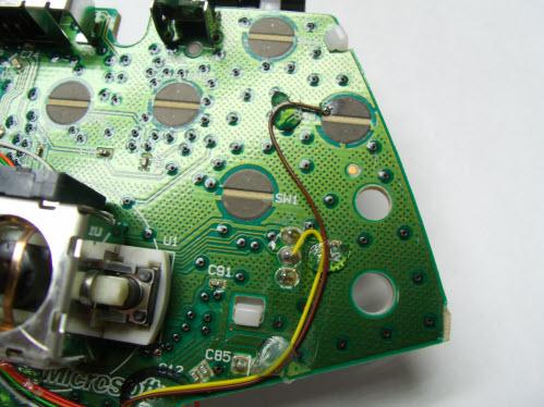
14 BROWN wire (B button) To connect the wires from the chip to the B button, you will need to remove a very small area of the black coating that is covering the pad. This is easiest done with a small pocket knife or razor blade. Lightly scrape the black coating to expose the bare copper underneath. Be careful to only scrape the coating from the corner's pad. Next you will want to Tin the pad. Tinning means you want to coat the pad with solder. This makes connecting the wire later much easier. To do this you will want to place the tip of your soldering iron on the pad to heat the pad and touch the solder to the pad (try avoiding touching the solder to the soldering iron) and the solder should flow onto the pad. You should end up with a little bubble of solder like you see below. It is important to keep the wires as short as possible and keep them out of the black circles. If you cross over a black circle it could possibly prevent one of the buttons on your controller from working when you put it back together. Also be sure to use only a small amount of solder as we have done.
, you can easily make a")
 to use it to")
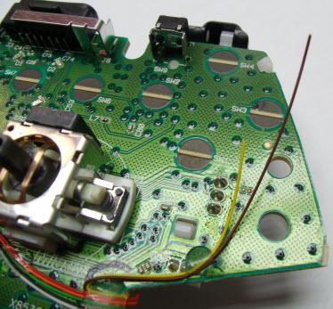
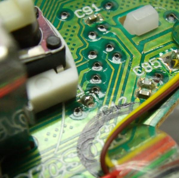
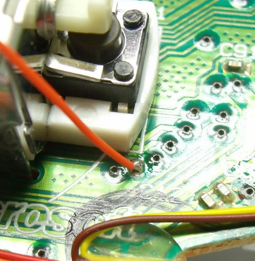
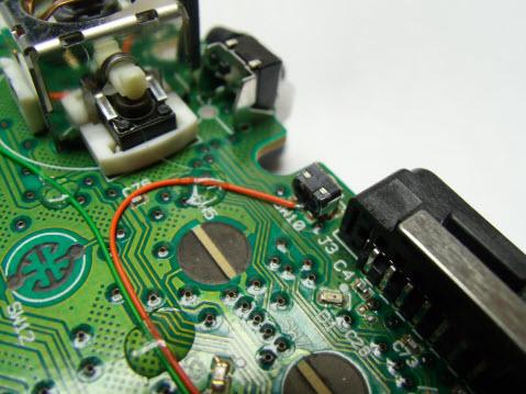
15 ORANGE wire (SYNC/MODE button) TIP: It is a little hard to make a good connection if you don't have soldering experience and the right tools (pencil soldering iron, magnifiers), you can easily make a short circuit between the legs of the SYNC button, causing a malfunction of the controller and the Mod Chip. In that case we strongly recommend you to install the Tactile push button (provided) to use it to change modes.


16 CG2 Board - ORANGE wire - Alternative connection In the NEW Style - CG2 controller, you can connect the ORANGE wire to the middle leg of the SYNC button, OR you can solder it to this point CONNECT THE ORANGE WIRE HERE Carefully, with a small knife, clean the solder point. Don t press hard or you will cut the copper trace. Apply a little bit of solder
17

18 WHITE wire (LED) 3rd PLAYER LED ALTERNATIVE INSTALLATION D1 D2 D3 D4 WHITE From Chip Mod CG - CG2 BOARDS
19
20


21 OPTIONAL MODE SWITCH If you want to use the TACT SWITCH instead of the SYNC BUTTON to change the Rapid Fire Modes: Drill one hole with a 5/32 drill bit. Next use hot glue to secure the button in place. Do not attempt to use Super Glue or any other adhesives as it will soak into the button mechanism and cause it to stop working. Connect one pin of the Tact switch to the ORANGE wire and the other pin to GROUND. DRILL HERE OR HERE

22 XMOD A GROUND TACTILE SWITCH BLACK CONNECT TO POINT A GROUND - NEGATIVE PUSH BUTTON MODE SWITCH ORANGE CONNECT HERE OPTIONAL PUSH BUTTON MODE SWITCH The installation of this switch is OPTIONAL. If you install this pushbutton, don t connect the ORANGE wire to the SYNC button.


23 The last thing you need to do is reassemble everything. The easiest way we found to do this is to leave the top piece face down so all the buttons do not fall out, and hold the PCB to the back of the controller and flip it over on the top case. Align the rumble motors so they are in their holders and lay the PCB and back of the case onto the front of the case. Keep it face down and use your finger to work the thumb sticks through the holes and work the case closed. Do not force it, you may have wires preventing the case from closing entirely. Just go slow and look at any areas to see what is stopping it from closing all the way. Now just screw the controller back together and you re done.
 MOD CHIP Our RAPID FIRE KIT uses the RIGHT TRIGGER to fire your weapon.")
24 PCB totally Assembled with Soldered wires 5 Main Modes - Fully programmable Auto Drop Shot (with or without Rapid Fire) Auto Quick Scope (with or without Rapid Fire) Akimbo - Aim assisted Quick ON-OFF 2 LEDs indicators Stealth (No extra button needed) MOD CHIP Our RAPID FIRE KIT uses the RIGHT TRIGGER to fire your weapon. Simply choose the rapid fire setting (23 combinations) you are most satisfied with, and press the trigger to fire. It will dramatically increase your performance and accuracy during the game play. This RAPID FIRE KIT has been designed specifically for the Call of Duty series, but works great for almost all first person shooters. This controller is 100% online compatible with recent game patches. Online compatible with COD , GOW 1-2, Halo 3, Halo ODST, Battlefield Bad Company 2, Left 4 Dead 1-2, and more!!! RAPID FIRE MODES To change modes: TAP the controller s SYNC button to cycle through the 5 main modes. The 3rd Player LED will blink to indicate the mode you are in. XMOD Rapid Fire - 23 mode Rapid Fire OFF Drop Aim Shot Quick Scope Akimbo Akimbo COD 5 Drop Shot Adjustable Mode 1 Mode 2 Mode 3 Mode 4 Mode 5
25 USER PROGRAMMABLE MODES These adjustable rapid fire modes gives you the freedom to easily make your own speed. You can choose anywhere from 5sps - 45sps. In that range, there are 60 speeds to select from. You can slow down automatic weapons to pinpoint precision or even speed single shot weapons to unreal speeds. Speed adjustments are made directly from the controller, no need to hook up to a computer to change the settings. During the programming process to see how your weapon responds to it, you can check the speed in real game by pressing the Right Trigger at any time. AUTOMATIC DROP SHOT Just by pushing the Right Trigger it will drop you all the way to the ground, aim and shoot, all in one action. When you come face to face with an opponent just press the RIGHT TRIGGER and you instantly lay on the floor as you shoot with rapid fire, as your opponent shoots over your head. You never need to remove your thumb off from the Right thumbsticks to press the "B" button, so your aim will never be affected and this makes the difference between living and dying, giving you a massive advantage over other players. This exclusive feature works with all Call of Duty games. With this function, when you push the LEFT Trigger the auto drop will be temporarily disabled (LT Cancel) and you will fire with REGULAR Rapid Fire letting you stay behind a barrier or window aiming down the sight and shoot without dropping. The Auto Drop Shot will be automatically enabled as soon as the Left Trigger is released. You can quickly activate/deactivate the AUTOMATIC DROP SHOT at any time in any mode. *** Drop shot will only work with DEFAULT TACTICAL BUTTONS settings and you can still use your "B" button as normal. AUTO QUICK SCOPE Push the RIGHT TRIGGER only to scope and shoot at the same time with rapid fire. **Quick Scope not available for "quick sniping" (rifles snipers) due to COD game patch.this patch has pretty much completely removed the ability to quick sniping. You have to wait half a second for it to be accurate, that is how they are preventing that. AKIMBO-MIMIC MODE Tired of holding both, Left and Right Triggers for your akimbo pistols? This function solves your problem. Put the controller into AKIMBO-MIMIC mode, pull the RIGHT TRIGGER ONLY and watch BOTH pistols fire. COD 5 COMPATIBLE MODE To play Call of Duty 5 "World at War" online the Rapid Fire Mod must be set in mode 5 on Default Speed. QUICK ON/OFF The Rapid Fire Function will be OFF at startup (when the Battery Pack is inserted). To turn the Rapid Fire ON-OFF: Hold down the LEFT TRIGGER and Tap the SYNC Button. No need to cycle through all the modes. LED INDICATORS This XMOD Rapid Fire Kit uses the 4th player LEDs exclusively as a status indicator for a complete and easy look of the current functions. Note that just the 1st,2nd and 3rd Player LEDs will flash when you SYNC or connect the controller with the XBOX 360 console.
26 FACTORY DEFAULT You can easily reset to default configuration. It will clear all data and restore all settings to the factory default values. Holding down the SYNC button for the normal 2-3 seconds will still allow you to synchronize your wireless controller to any XBOX 360 System. The chip will remember the fire rate even when you turn your controller off or remove the batteries. SPECIAL MODES To enter in the Special Modes with or without Rapid Fire: - Hold The RIGHT TRIGGER and TAP the SYNC button. ** - The LEDs will light and stay solid waiting for your input. Next: - Tap the button to set your desired sub-mode (drop shot, quick scope or akimbo): With Rapid Fire QUICK SCOPE AKIMBO DROP SHOT CANCEL HOLD for 8 sec. to RESET to Factory Default settings XMOD Rapid Fire - 23 mode Without Rapid Fire QUICK SCOPE CANCEL DROP SHOT XMOD Rapid Fire - 23 mode To CANCEL or DEACTIVATE any Special mode: - Enter in the Special Modes (RT + Sync). ** - Tap the Cancel Button or Tap the function button (Quick Aim, Akimbo or Drop Shot) again ** After entering in the Special Mode by pressing the RT and the Sync button, wait for one second before taping any other button to prevent the controller to start syncing with the XBOX console.

27 PROGRAMMING MODES The speed of all 5 Main modes can be programmed at any time. You can choose anywhere from 5 sps - 45 sps. In that range, there are 60 speeds to select from. To enter in the programming mode: - Hold the LEFT and RIGHT triggers and TAP the SYNC button. - Tap the B button to increase the speed. - Tap the SYNC button to decrease the speed. The LEDs will flash when you reach the minimum or maximum speed. You can test the speed by pressing the Right trigger at any time. To SAVE & EXIT: - Hold the LEFT trigger and Tap the SYNC button. To set the Factory Default speed (just the mode you are in) and EXIT: - Hold the RIGHT trigger and Tap the SYNC button. This mod chip can remember different Rapid Fire speeds in "shots per second". It s important to know that each video game may have a speed cap. This cap can be different for every game. If you try to set your Rapid Fire speed above this cap, your gun will actually shoot slower, or not shoot at all. Always try starting out at a slower speed and increase your speed in small intervals. Start out at a low speed, then increase it until you feel that the gun is starting to "sputter" or slow down. At that point, you are probably reaching the game's speed cap. Many different factors can affect the performance of your Rapid Fire controller, including your console, the quality of your Internet connection and whether or not you are the current host of the match. SAVE & EXIT DECREASE SPEED DEFAULT SPEED & EXIT INCREASE SPEED XMOD Rapid Fire - 23 mode RESET TO FACTORY DEFAULT You can reset all seed modes to factory default settings. -Enter to the SPECIAL MODES (Hold RT and TAP the SYNC button) -Hold the B button for 8 sec. FACTORY DEFAULT SPEEDS (shots per seconds) MODE 1: 10 sps. MODE 2: 15 sps. MODE 3: 25 sps. MODE 4: 40 sps. MODE 5: 12 sps. ( COD 5 Call of Duty 5 World at War )
XMOD RAPID FIRE MOD KIT 20 MODES - v4 INSTRUCTIONS
 v4 ELECTRONICS XMOD RAPID FIRE MOD KIT 20 MODES - v4 INSTRUCTIONS This tutorial is designed to aid you in the installation of a XMOD Rapid Fire microchip. This installation requires soldering several wires
XMOD 18 Mode Rapid Fire Mod Chip
 XMOD 18 Mode Rapid Fire Mod Chip INSTALLATION INSTRUCTIONS - PCB version 2 This tutorial is designed to aid you in the installation of a Rapid Fire microchip. This installation requires soldering several
Installation tutorial for Console Customs Xbox Mode Dual Button (RFX-5B) Rapid fire Microchip for all Wired and Wireless controllers
 Rapid fire Microchip for all Wired and Wireless controllers") Installation tutorial for Console Customs Xbox 360 5-Mode Dual Button (RFX-5B) Rapid fire Microchip for all Wired and Wireless controllers This tutorial is designed to aid you in installation of a console
Installation tutorial for Console Customs Xbox 360 5-Mode Dual Button (RFX-5B) Rapid fire Microchip for all Wired and Wireless controllers This tutorial is designed to aid you in installation of a console
Installation tutorial for Console Customs Xbox 360 MaxFire LITE rapid fire Mod Chip.
 Installation tutorial for Console Customs Xbox 360 MaxFire LITE rapid fire Mod Chip. This tutorial is designed to aid you in installation of a console customs MaxFire LITE modchip. This tutorial covers
Installation tutorial for Console Customs Xbox 360 Dual Rapid fire Microchip for wired and wireless controllers (all versions)
") Installation tutorial for Console Customs Xbox 360 Dual Rapid fire Microchip for wired and wireless controllers (all versions) This tutorial is designed to aid you in installation of a console customs
Installation tutorial for Console Customs Xbox 360 Dual Rapid fire Microchip for wired and wireless controllers (all versions) This tutorial is designed to aid you in installation of a console customs
30 MODE PLUS. XMOD Modded Controller. User s Manual
 30 MODE PLUS XMOD Modded Controller User s Manual Turn on your wireless controller and the console Press the Xbox button on the wireless controller to turn on both the controller and the console. Open
Installation tutorial for Console Customs PS3 TrueFire Standard Rapid fire Microchip for Sixaxis and Dualshock 3 controllers
 Installation tutorial for Console Customs PS3 TrueFire Standard Rapid fire Microchip for Sixaxis and Dualshock 3 controllers This tutorial is designed to aid you in installation of a console customs rapid
Installation tutorial for Console Customs Xbox ONE MaxFire ONE V2 PCB
 Installation tutorial for Console Customs Xbox ONE MaxFire ONE V2 PCB This tutorial is designed to aid you in installation of a console customs MaxFire ONE V2 Circuit board in the newer Xbox One Controllers
Getting to know your controller
 Congratulations on purchasing the World s Fastest Rapid Fire, Fact! We are sure you will love all the Arbiter 3 has to offer, and we are always welcome of suggestions on improvements and extra features
UserManual
 UserManual Rapid Fire Burst Fire Akimbo Jitter Quick Scope Mimic Drop Shot Jump Shot GOW Perfect Reloads Auto Aim Quick Reload Auto Spotting Auto Run Sniper Breath 10 Programmable Modes Reflex Remapping
CONTENTS. Akimbo (Left Trigger Rapid Fire)
") CONTENTS Page 1: Introduction, Feature access Page 2: Rapid Fire, Burst Fire, Akimbo, Mimic Page 3: Default Modes, Changing Modes, Adjustable Fast Reload Page 4: Sub Modes, Drop Shot, Jump Shot, Automatic
CONTENTS Page 1: Introduction, Feature access Page 2: Rapid Fire, Burst Fire, Akimbo, Mimic Page 3: Default Modes, Changing Modes, Adjustable Fast Reload Page 4: Sub Modes, Drop Shot, Jump Shot, Automatic
PS4. Ragnarok Flex Modchip Installation Instructions.
 PS4 Ragnarok Flex Modchip Installation Instructions Revised 11/25/2013 Tools needed PS4 Controller Viking PS4 Ragnarok Flex modchip DIY Kit (includes mod chip, LED board, and LED lense) Two diodes (included
Xbox One / PS4 Guide. Xbox One Quick Guide. PlayStaJon 4 Quick Guide MODE SPEED COMPATIBLE GAMES MODE SPEED COMPATIBLE GAMES
 Xbox One / PS4 Guide This guide will cover all aspects of your Xbox One PlayStation 4 controller. Please read all parts of this guide befe setting up and using your Xbox One PlayStation 4 controller. Please
CONTENTS. or + Akimbo (Dual Trigger Rapid Fire)
") CONTENTS Page 1: Introduction, Feature Access Page 2: Sub Modes, Rapid Fire, Burst Fire, Akimbo, Mimic Page 3: Default Modes, Changing Modes, Adjustable Fast Reload Page 4: Jitter Fire, Drop Shot, Jump
CONTENTS Page 1: Introduction, Feature Access Page 2: Sub Modes, Rapid Fire, Burst Fire, Akimbo, Mimic Page 3: Default Modes, Changing Modes, Adjustable Fast Reload Page 4: Jitter Fire, Drop Shot, Jump
Ragnarok PS4 Flex Mod Chip Operation Instructions
 www.viking360.com Introduction The Viking Ragnarok software platform was developed to make it easier for customers to mix and match mods, on the fly, without needing to scroll through massive numbers of
or + Akimbo (Dual Trigger Rapid Fire)
") Page 1: Introduction, Feature access Page 2: Rapid Fire, Burst Fire, Akimbo, Mimic Page 3: Default Modes, Changing Modes, Adjustable Fast Reload Page 4: Sub Modes, Drop Shot, Jump Shot, Automatic Sniper
Page 1: Introduction, Feature access Page 2: Rapid Fire, Burst Fire, Akimbo, Mimic Page 3: Default Modes, Changing Modes, Adjustable Fast Reload Page 4: Sub Modes, Drop Shot, Jump Shot, Automatic Sniper
INSTRUCTION MANUAL XBOX ONE JUGGERNAUT VER 5.1
 INSTRUCTION MANUAL XBOX ONE JUGGERNAUT VER 5.1 Congratulations, welcome to the GamerModz Family! You are now a proud owner of a GamerModz Custom Modded Controller. The JUGGERNAUT - VER 5.1 FOR XBOX ONE
INSTRUCTION MANUAL PS4 JUGGERNAUT VER 7.0
 INSTRUCTION MANUAL PS4 JUGGERNAUT VER 7.0 Congratulations, welcome to the GamerModz Family! You are now a proud owner of a GamerModz Custom Modded Controller. The JUGGERNAUT - VER 7.0 FOR PS4 has been
To maximize your potential, be sure to read the instructions fully before operating the Mega Mod.
 You are now the proud owner of our exclusive Mega Mod! The Mega Mod is our ultimate modded controller and features all of the mods that we offer for the PlayStation 3. The Mega Mod comes with 9 different
CONTENTS. or + Akimbo (Left Trigger Rapid Fire)
") CONTENTS Page 1: Introduction, Feature access Page 2: Rapid Fire, Burst Fire, Akimbo, Mimic Page 3: Default Modes, Changing Modes, Adjustable Fast Reload Page 4: Sub Modes, Drop Shot, Jump Shot, Automatic
CONTENTS Page 1: Introduction, Feature access Page 2: Rapid Fire, Burst Fire, Akimbo, Mimic Page 3: Default Modes, Changing Modes, Adjustable Fast Reload Page 4: Sub Modes, Drop Shot, Jump Shot, Automatic
How to add a push power button to your XBOX S-Type controller
 26.10.2006 Page 1 of 5 http://synapse.wordpress.com How to add a push power button to your XBOX S-Type controller - By Synapse Required Items - XBOX S-Type controller (Wireless ones won t work) Soldering
Arsenal One Install Instructions for Xbox One Controller
 Arsenal One Install Instructions for Xbox One Controller arsenalmod.com Page 1 of 14 Before Proceeding These instructions are for the install of the Arsenal One 28 pin chip for the Xbox One. READ ALL INSTRUCTIONS
Lighthouse Beginner s soldering kit
 Lighthouse Beginner s soldering kit Kit contains: 1 x 220 ohm resistor (Red, Red, Black) 1 x 82k ohm resistor (Grey, Red, Orange) 2 x 220k ohm resistors (Red, Red, Yellow) 2 x Diodes 1 x Power switch 1
Installation Guide for Custom Console Mods Xbox 360 (LED kit)
") Installation Guide for Custom Console Mods Xbox 360 (LED kit) This mod kit works for all versions of the Xbox 360 wireless controllers. This guide is designed to aid you in installing the LED kit from
Installation Guide for Custom Console Mods Xbox 360 (LED kit) This mod kit works for all versions of the Xbox 360 wireless controllers. This guide is designed to aid you in installing the LED kit from
Circuit Board Assembly Instructions for Babuinobot 1.0
 Circuit Board Assembly Instructions for Babuinobot 1.0 Brett Nelson January 2010 1 Features Sensor4 input Sensor3 input Sensor2 input 5v power bus Sensor1 input Do not exceed 5v Ground power bus Programming
Never power this piano with anything other than a standard 9V battery!
 Welcome to the exciting world of Digital Electronics! Who is this kit intended for? This kit is intended for anyone from ages 13 and above and assumes no previous knowledge in the field of hobby electronics.
ArduTouch Music Synthesizer
 ArduTouch Music Synthesizer Assembly Instructions rev C Learn To Solder download for free at: http://mightyohm.com/soldercomic The following photos will show you how to solder. But feel free to download
STRIKEPACK F.P.S. DOMINATOR MODE UPGRADE
 STRIKEPACK F.P.S. DOMINATOR MODE UPGRADE Once your StrikePack has received the Dominator upgrade, you can refer to the rest of this document for operation instructions. UPGRADING THE STRIKEPACK Open the
Pioneer Elite CLD-97 Digital Noise Reduction (DNR) Auto-off Mod DIY Installation Guide
 Auto-off Mod DIY Installation Guide") Pioneer Elite CLD-97 Digital Noise Reduction (DNR) Auto-off Mod DIY Installation Guide Background: The CLD-97 laserdisc player has one of the best video quality outputs of any laserdisc player released.
Pioneer Elite CLD-97 Digital Noise Reduction (DNR) Auto-off Mod DIY Installation Guide Background: The CLD-97 laserdisc player has one of the best video quality outputs of any laserdisc player released.
INSTRUCTION MANUAL PS4 SPS-X2 VER 4.0
 INSTRUCTION MANUAL PS4 SPS-X2 VER 4.0 Congratulations, welcome to the GamerModz Family! You are now a proud owner of a GamerModz Custom Modded Controller. The SPS-X2 - VER 4.0 FOR PS4 has been completely
Bill of Materials: Metronome Kit PART NO
 Metronome Kit PART NO. 2168325 The metronome kit allows you to build your own working electronic metronome. Features include a small speaker, flashing LED, and the ability to switch between several different
The Useless Machine. DIY Soldering Edition. Instruction Guide v0004
 The Useless Machine DIY Soldering Edition Instruction Guide v0004 TM For the best outcome, follow each step in order. We recommend reading this guide entirely before you get started. Tools required: Soldering
DC Motor. Controller. User Guide V0210
 DC Motor Controller User Guide 59757 V0210 This kit provides a great exercise of intermediate soldering skills and creates a device that enables you to control various Pitsco motors, Tamiya gearboxes,
Modifying the Hextronik HX5010 Servo Motors for Babuinobot 1.0
 Modifying the Hextronik HX5010 Servo Motors for Babuinobot 1.0 Brett Nelson January 2010 1 Converting the Hextronik HX5010 to a Geared DC Motor The following pages will describe step by step the process
Repairing Microsoft Wedge Touch Mouse Battery Cover Retaining Clip
 Repairing Microsoft Wedge Touch Mouse Battery Cover Retaining Clip Disassembly, repair and reassembly of Wedge Touch mouse when the battery cover will not stay closed. Also is a good guide to repair other
Instructions for Lighting an S Scale Caboose
 Instructions for Lighting an S Scale Caboose The S Scale Caboose lighting kit is adaptable for most caboose models of rolling stock including American Flyer (TM) and contains the same components as found
Intellivision A/V Mod Installation Guide
 Intellivision A/V Mod Installation Guide This document will guide you through installing your Intellivision A/V Mod Kit to your Intellivision I, II, and III game consoles. Installation is basically the
Explorer Wiring Kit (assembled)
") Explorer Wiring Kit (assembled) For Vintage, Firestorm & Standard Series Please Read All Instructions Before Beginning. Tools you will need: Soldering Iron (35 watt preferably) Solder Wet Sponge Wire Clippers
Explorer Wiring Kit (assembled) For Vintage, Firestorm & Standard Series Please Read All Instructions Before Beginning. Tools you will need: Soldering Iron (35 watt preferably) Solder Wet Sponge Wire Clippers
Star Trek TOS communicator upgrade kit Install instructions Hyperdyne Labs 2002
 Star Trek TOS communicator upgrade kit Install instructions Hyperdyne Labs 2002 Package Your package should include: Assembled TOS sound/motor/light board with LEDs and sound chip Moiré motor 9V snap connector
Assembly Instructions: Kit #5
 Assembly Instructions: Kit #5 1. Insert the T-pin into one of the caps. 2. Insert the rotor core into the same cap as shown below. Apply some pressure to push the rotor core approximately 1/2" (10-12 mm)
tinycylon Assembly Instructions Contents Written by Dale Wheat Version August 2016 Visit dalewheat.com for the latest update!
 tinycylon Assembly Instructions Written by Dale Wheat Version 2.1 10 August 2016 Visit dalewheat.com for the latest update! Contents Assembly Instructions...1 Contents...1 Introduction...2 Quick Start
XBOX ONE FOR STRIKEPACK F.P.S. DOMINATOR WIRED NEXT GENERATION MOD PACK
 FOR XBOX ONE STRIKEPACK F.P.S. DOMINATOR WIRED NEXT GENERATION MOD PACK Introduction 3 Kit Includes 3 Getting started 4 - Attaching & Pairing the StrikePack F.P.S. Dominator Important Terminology 5 Modology
PS4 FOR STRIKEPACK F.P.S. DOMINATOR WIRED NEXT GENERATION MOD PACK
 FOR PS4 STRIKEPACK F.P.S. DOMINATOR WIRED NEXT GENERATION MOD PACK Introduction 3 Getting started - Attaching the StrikePack F.P.S. Dominator 4 - Pairing the StrikePack F.P.S. Dominator with Your Console
FM Wireless Microphone Kit Instructions for Assembly Page 1 of 5
 Instructions for Assembly Page 1 of 5 1. Find Resistor R1. Remove any tape that may be attached to the leads. Bend the leads as needed to insert Resistor R1 into the printed circuit board in the holes
PS4 FOR STRIKEPACK F.P.S. DOMINATOR WIRED NEXT GENERATION MOD PACK
 FOR PS4 STRIKEPACK F.P.S. DOMINATOR WIRED NEXT GENERATION MOD PACK Introduction 3 Getting started - Attaching the StrikePack F.P.S. Dominator 4 - Pairing the StrikePack F.P.S. Dominator with Your Console
Kindle 3 Remote Page Turn Switch Replacement
 Kindle 3 Remote Page Turn Switch Replacement How to add a remote (wired) page turning switch to the Kindle 3. Written By: AnotherBrian ifixit CC BY-NC-SA www.ifixit.com Page 1 of 10 INTRODUCTION This guide
The Useless Machine. Parts Only - Build Guide v0001
 TM The Useless Machine Parts Only - Build Guide v0001 For the best outcome, follow each step in order. We recommend reading this guide entirely before you get started. Tools required: One phillips screwdriver,
Congratulations on your purchase of the SparkFun Arduino ProtoShield Kit!
 Congratulations on your purchase of the SparkFun Arduino ProtoShield Kit! Well, now what? The focus of this guide is to aid you in turning that box of parts in front of you into a fully functional prototyping
Firefly Jar Learn to Solder Kit
 Firefly Jar Learn to Solder Kit Parts Tools A. Firefly Jar PCB B. 10mm Flickering LED (White or Yellow) C. Resistor D. Tilt Switch (Black or Green) E. Battery Holder F. Velcro ( Not Pictured) G. Jar (
Pacific Antenna Code Practice Oscillator Kit
 Pacific Antenna Code Practice Oscillator Kit This kit is offered to initiate the first time builder in the various techniques of mechanical and electronic kit construction. At the end of the approximately
Standard Kit #1 (3-way switch)
") Standard Kit #1 (3-way switch) Please Read All Instructions Before Beginning. Tools you will need: Soldering Iron (35 watt preferably) Solder Wet Sponge Wire Clippers 3/8 Drill Bit 1/4 Drill Bit Variable
Standard Kit #1 (3-way switch) Please Read All Instructions Before Beginning. Tools you will need: Soldering Iron (35 watt preferably) Solder Wet Sponge Wire Clippers 3/8 Drill Bit 1/4 Drill Bit Variable
Compatible with PS 3 /Xbox One wired controller (connect with charging cable).
.") Usage manual Product function: Maxgear Cross attack converter Xbox one controller on PS3 and PC is an adapter that allows you to connect your Wired Xbox One controller (connect with charging cable) to
Usage manual Product function: Maxgear Cross attack converter Xbox one controller on PS3 and PC is an adapter that allows you to connect your Wired Xbox One controller (connect with charging cable) to
LED Cup Holder Lights Installation Guide
 LED Cup Holder Lights Installation Guide (20112015 Kia Optima) Thanks for purchasing this LED Cup Holder Light Kit! If you have any questions or feedback please email us direct at Sales@K5OptimaStore.com
Signal Lights Demonstration Video Time Duration: - 38 sec. Use the right hand mouse button for video control.
 Tip: - Working Turntable Signals and Cabin Lights using Gold TC7.0F1 and Above Hi All, At long last I completed the project to have working signals and cabin lights on my turntable. This is a record of
Cylon Raider Lighting Kit
 Cylon Raider Lighting Kit By Madman Lighting Inc Copyright June 2015, all rights reserved. All trademarks property of their respective owners. WARNING: This product contains small parts not suitable for
Application Note. Bowser-Stewart VO-1000 Tsunami Digital Sound Decoder Installation Notes
 Application Note Overview This application note describes how to install a TSU-1000 Digital Sound Decoder into the Bowser-Stewart VO-1000 Locomotive. Skill Level 4: The entire installation can be completed
Standard Kit #1 (5-way switch)
") Standard Kit #1 (5-way switch) Please Read All Instructions Before Beginning. Tools you will need: Soldering Iron (35 watt preferably) Solder Wet Sponge Wire Clippers 3/8 Drill Bit 1/4 Drill Bit Variable
Standard Kit #1 (5-way switch) Please Read All Instructions Before Beginning. Tools you will need: Soldering Iron (35 watt preferably) Solder Wet Sponge Wire Clippers 3/8 Drill Bit 1/4 Drill Bit Variable
Razr Adapter Retrofit Project by Craig Hoy, Edmonton, AB, Canada
 Razr Adapter Retrofit Project by Craig Hoy, Edmonton, AB, Canada The following is a description of the process that I have used to modify the console eject box for e38, e39, e46 and x5 s, part number 84-21-6-933-415.
Congratulations on purchasing the Spirit Rails Magnetic Attach that allows easy wand to pack removal and reattachment by just getting close!
 Introduction Congratulations on purchasing the Spirit Rails Magnetic Attach that allows easy wand to pack removal and reattachment by just getting close! The Spirit Rails Magnetic Attach Kit is designed
Telecaster Wiring Kits Please Read All Instructions Before Beginning. Tools you will need: Soldering tips: Removing Current Wiring: Step 1. Step 2.
 Telecaster Wiring Kits Please Read All Instructions Before Beginning. Tools you will need: Soldering Iron (35 watt preferably) Solder Wet Sponge Wire Clippers Wire Strippers 3/8 Drill Bit 5/32 Drill Bit
Pacific Antenna Low Pass Filter Kit
 Pacific Antenna Low Pass Filter Kit Description Many basic transmitter and/or transceiver designs have minimal filtering on their output and frequently have significant harmonic content in their signals.
Smartlamp SINGLE LED Kit - Construction Manual
 Smartlamp SINGLE LED Kit - Construction Manual With this construction manual and a Smartlamp Single LED Kit you can assemble your own solar lamp. It is recommended to first read the instructions before
Written By: Walter Galan
 Xbox 360 CPU Heat Sink Replacement CPU heat sink replacement. Written By: Walter Galan ifixit CC BY-NC-SA www.ifixit.com Page 1 of 27 INTRODUCTION Use this guide to remove the CPU heat sink from your Xbox
Blue Ring Tester Kit Assembly & User Manual
 Blue Ring Tester Kit Assembly & User Manual Alltronics LLC/AnaTek Instruments 2761 Scott Blvd, Santa Clara, CA, 95050, USA March 2015 Edition Tel: 408-778-3868, Fax: 408-778-2558, E mail : tech@alltronics.com
Solar Panels Build Your Own Instructions for the Do It Yourself Person Let s have some fun!
 Solar Panels Build Your Own Instructions for the Do It Yourself Person Let s have some fun! Before we get started lets talk about a few things like materials and tools. Let s start off with tools as Lowes
INSTRUCTION MANUAL PS4 SPS-X1 VER 4.0
 INSTRUCTION MANUAL PS4 SPS-X1 VER 4.0 Congratulations, welcome to the GamerModz Family! You are now a proud owner of a GamerModz Custom Modded Controller. The SPS-X1 - VER 4.0 FOR PS4 has been completely
Lesson 2: Soldering. Goals
 Introduction: Its time to learn how to solder. So you have met all the components needed to make a DIY Gamer, now it s time to put it together. Soldering is joining the components to the printed circuit
Xbox One. Arbiter 5. User guide. Rev Speed Head Shot Controllers.
 Xbox One Arbiter 5 User guide Rev 1.1 25 Speed Head Shot Controllers www.headshotcontrollers.co.uk Arbiter 5.0 Customization menu To change and configure the Arbiter you must first enter the customization
Instructions to Convert a 4-foot Florescent Fixture to LEDs Using 60W Power Supply Using 2 or 3 strips 30Dec15
 Instructions to Convert a 4-foot Florescent Fixture to LEDs Using 60W Power Supply Using 2 or 3 strips 30Dec15 Thank you for purchasing the Shoplight Solutions 4-ft conversion kit. This is a companion
Harmony Remote Repair
 Harmony Remote Repair harmonyremoterepair.com How to install your new Harmony One Front Cover/Touch Screen Important! Before you begin working on your Harmony One, you must discharge any static electricity
Asus ZenFone 2 Display Replacement
 Asus ZenFone 2 Display Replacement Replace your display if it isn't functioning correctly or if it is cracked or broken. Written By: Jessica Nguyen ifixit CC BY-NC-SA www.ifixit.com Page 1 of 14 INTRODUCTION
The IntoPlay build. This section will show how to fill the components into the case halves, and also the case base, which will look like this:
 The IntoPlay build Ok, I presume you have read the sections about cutting the holes in the case front, speaker holes and spray painting, modding components, preparing the case, etc. So far, the guides
DEM ABPM KIT All Band Power Meter Assembly Notes and Pictures
 DEM ABPM KIT All Band Power Meter Assembly Notes and Pictures Paul Wade W1GHZ w1ghz@arrl.net Down East Microwave has kindly agreed to make kits available for my All Band Power Meter (Note: I receive no
Curium 19H Installation Instructions & Parts List
 Curium 19H Installation Instructions & Parts List Illustration Curium 19H Right Hand Page 1 of 15 01/07/2016 Revision 2.1 IMPORTANT This shower screen / enclosure must be installed by suitably qualified
Electronics Merit Badge Class 4. 12/30/2010 Electronics Merit Badge Class 4 1
 Electronics Merit Badge Class 4 12/30/2010 Electronics Merit Badge Class 4 1 Soldering Safety Note: A Soldering Iron gets hotter than 374 F. Do not touch the soldering iron s metal parts or you will receive
Team Xecuter Joycon Mod By: XxWiReDxX
 Team Xecuter Joycon Mod By: XxWiReDxX Works With Every Switch SX OS Works with every Nintendo Switch and every firmware version! Play Every Game With SX OS you can play all your favorite games straight
Gat ew ay T o S pace AS EN / AS TR Class # 07. Colorado S pace Grant Consortium
 Gat ew ay T o S pace AS EN / AS TR 2500 Class # 07 Colorado S pace Grant Consortium One Minute Reports: - Can we have two data loggers? - Do you provide us with cameras? {Hardware Checkout after proposal}
Understanding the 302 point motor.
 PAGE 1 Understanding the 302 point motor. All of our point motors are fully tested before posting to you, and we thank you for your order and wish you many years of happy operation. Our helpline is open
Stream NXT - assembly instructions
 Stream NXT - assembly instructions Recommended settings CG (measured from root leading edge): Speed/launch camber (+down, near the wing root): Cruise camber (+down, near the wing root): Thermal camber
Make an Altoids Flashlight.
 Make an Altoids Flashlight by JoshuaZimmerman on July 12, 2012 Table of Contents Make an Altoids Flashlight 1 Intro: Make an Altoids Flashlight 2 Step 1: Parts 2 Step 2: LED Holder 3 Step 3: Prepare Your
Any Questions? Contact us or BSA Atomic Blinkie
 BSA Atomic Blinkie The heart of this blinkie is a tiny electronic chip embedded in each of the three LEDs. When power is applied, the chip tells the LED to turn on and off, or fade different colors By
Assembly instructions for the CS-1 ChemShield
 Page 1 Of 6 Assembly instructions for the CS-1 ChemShield What is S.M.D SMD=Surface mount devices, like all the components does not have leads, but gets soldered onto flat solder pads. The CS-1 assembly
Under Seat Storage Drawer Installation Instructions
 Under Seat Storage Drawer Installation Instructions Parts List: 1) Drawer Assembly 8) Self Tapping Screws 1) Instructions 1) Template Tools Needed: Drill and/or Bit Driver Tape Measure Jigsaw or metal
Lesson 2: Soldering. Goals
 Introduction: Its time to learn how to solder. So you have met all the components needed to make a DIY Gamer, now it s time to put it together. Soldering is joining the components to the printed circuit
The ability to make basic voltage and resistance measurements using a digital multimeter
 Congratulations on your purchase of a new OneShot chassis! The PC01 OneShot combines a rugged enclosure, power supply, and discrete instrument DI in a compact 1/4U package. A few minutes of assembly are
AR.Drone 2 - Main Board External Antenna Modification Procedure. Document Number: EAM Check back for updates.
 Document Number: EAM-20130303-2 Check back for updates. 3/22/2013 NOTE: Along with this mod procedure, you will also need to: 1. Remove the Main Board. Refer to the Main Board Removal Procedure 2. Adapt
Pacific Antenna 20 and 40M Lightweight Dipole Kit
 Pacific Antenna 20 and 40M Lightweight Dipole Kit Diagram showing configuration and approximate lengths 8 6 16 9 16 9 8 6 Description The Pacific Antenna lightweight dual band, trap dipole kit provides
Instructions to Convert a 4-foot Florescent Fixture to LEDs Using 100W Power Supply Using 1-4 strips 30Dec15
 Instructions to Convert a 4-foot Florescent Fixture to LEDs Using 100W Power Supply Using 1-4 strips 30Dec15 Thank you for purchasing the Shoplight Solutions 100W conversion kit. This is a companion document
Introduction 1. Download socket (the cable plugs in here so that the GENIE microcontroller can talk to the computer)
") Introduction 1 Welcome to the magical world of GENIE! The project board is ideal when you want to add intelligence to other design or electronics projects. Simply wire up your inputs and outputs and away
Introduction 1 Welcome to the magical world of GENIE! The project board is ideal when you want to add intelligence to other design or electronics projects. Simply wire up your inputs and outputs and away
PRO 400 M401 MFP M425 CF-280A/X TONER CARTRIDGE REMANUFACTURING INSTRUCTIONS
 HP PRO 400 M401 MFP M425 CF-280A/X TONER CARTRIDGE REMANUFACTURING INSTRUCTIONS HP CF-280A/X TONER CARTRIDGE REMANUFACTURING THE HP LASERJET PRO 400 M401/MFP M425 (CF-280A/X) TONER CARTRIDGE By Mike Josiah
Application Note. Atlas B23-7 Tsunami Digital Sound Decoder Installation Notes
 Application Note Atlas B23-7 Tsunami Digital Sound Decoder Installation Notes Overview This application note describes how to install a TSU-1000 digital sound decoder into an Atlas B23-7. Skill Level 2:
Warning: CHOKING HAZARD -Small Parts. Not for Children Under 9 yrs. Kit Recommended for Ages 12 and up.
 The Original Warning: CHOKING HAZARD -Small Parts. Not for Children Under 9 yrs. Kit Recommended for Ages 12 and up. Table of Contents Soldering.. 3 How the WASP Works.. 7 The Build...... 12 Troubleshooting......30
Nikon D70 Eyepiece Replacement
 Replace the Eyepiece in your Nikon D70. Rédigé par: Andrew Bookholt ifixit CC BY-NC-SA fr.ifixit.com Page 1 de 21 INTRODUCTION Use this guide to replace the eyepiece cover that allows for focus compensation.
PS2-SMC-06 Servo Motor Controller Interface
 PS2-SMC-06 Servo Motor Controller Interface PS2-SMC-06 Full Board Version PS2 (Playstation 2 Controller/ Dual Shock 2) Servo Motor Controller handles 6 servos. Connect 1 to 6 Servos to Servo Ports and
A3 Pro INSTRUCTION MANUAL. Oct 25, 2017 Revision IMPORTANT NOTES
 A3 Pro INSTRUCTION MANUAL Oct 25, 2017 Revision IMPORTANT NOTES 1. Radio controlled (R/C) models are not toys! The propellers rotate at high speed and pose potential risk. They may cause severe injury
PS4 FOR STRIKEPACK F.P.S. DOMINATOR WIRED NEXT GENERATION MOD PACK
 FOR PS4 STRIKEPACK F.P.S. DOMINATOR WIRED NEXT GENERATION MOD PACK Introduction 3 Getting started - Attaching the StrikePack F.P.S. Dominator 4 - Pairing the StrikePack F.P.S. Dominator with Your Console
Firehouse Manual. Tools Needed:
 Tools Needed: -Cordless Drill (12V or higher) -#2 Square Drive Bit -Hammer -6 Step Ladder -Tape Measure -Square utility knife w/ blade & hook blade -Speed Square Little Cottage Co. PO Box 455 Berlin, OH
Curium 19.4H Installation Instructions & Parts List
 Curium 19.4H Installation Instructions & Parts List Illustration Curium 19.4H Right Hand Page 1 of 21 30/06/2016 Revision 1.0 IMPORTANT This shower screen / enclosure must be installed by suitably qualified
Bill of Materials: General Purpose Alarm, Pulsed PART NO
 General Purpose Alarm, Pulsed PART NO. 2190207 I hate alarms that sound continuously - unless they are smoke alarms. Smoke alarms should be annoying, but others should not. I wanted an alarm for a function
Solder is a metallic glue that holds the parts together and forms a connection that allows electrical current to flow.
 Proper Soldering & Desoldering High Performance Ultrasonic Range Finders Techniques of a MaxBotix Sensor Materials Needed for Soldering Goggles Hands-free clamp Wire stripper Soldering iron with stand