V Ford Mustang
|
|
|
- Carol Wilkinson
- 5 years ago
- Views:
Transcription
1 V Ford Mustang N2MB WOT Box Installation Instructions NOTE: If you have a CDI (capacitive discharge ignition system) please contact us at support@n2mb.com for additional instructions. Damage to your WOT Box can occur if the installation is not completed correctly! All stock ignitions are inductive, not capacitive; if you haven t installed a capacitive ignition system on your vehicle, it doesn t have one. WARNING: Spark based rev limiters can damage catalytic converters. If you have catalytic converters on your car, N2MB accepts no responsibility for damage caused by the WOT Box. This being said, many successful installs have been made on Catalytic Converter equipped vehicles. Damage usually is only caused by using the launch control feature for more than a few seconds, but once again, USE AT YOUR OWN RISK IF YOU HAVE CATALYTIC CONVERTERS! Please visit our website at for the latest version of the WOT Box software and installation instructions. Solder all joints. The N2MB recommended soldering method is available at Use a multimeter to verify all wires before they are cut or tapped into. The colors of wires from model year to model year may differ, and may be different on your car from those described in these instructions. Where discrepancies are known, they are described, but there may be more discrepancies than those listed. The best way to know that you have the right wire is to check the connectivity to the ECU and/or sensor at the pins described. In these instructions, pictures include other aftermarket alterations in addition to the WOT Box. N2MB is not affiliated with these devices. In addition, if you see something that isn t in your vehicle, don t worry. Route wires in the manner that you want them to lie permanently before connecting them. Cut wires to length before soldering; avoid coiling wires of excessive length as they can cause noise in the circuit, altering the operation of the WOT Box. Spending some extra time here will enhance the aesthetics of the install. Zip ties are included to secure the wires away from heat, moving parts, sharp edges, or anything else that can damage the wires.
2 Included in the WOT BOX kit: WOT Box Wiring harness USB to Serial Converter for future software upgrades Ground lug Zip ties Heat shrink tubing You will need: Wire Strippers Soldering Iron or Station Metric Socket Set Sandpaper Heat Shrink (if more than is included in the kit is needed) Electrical tape Zip Ties (if more than is included in the kit is needed) Razor Blade or Sharp Knife Multimeter or Ohm Meter Screwdriver or other sharp object RTV or Hot Glue (optional) 7/16 Rubber Grommet with ¼ internal hole WOT Box Wire Color Vehicle Wire Color Description Device PCM Bussed Electrical Center Blue Blue/White Accelerator Pedal 5 29B n/a Position Sensor Yellow Yellow/Violet Crankshaft Position 2 13E n/a Sensor Positive Green Green/Violet Cruise Control Clutch 1 21T n/a Switch (Clutch Deactivation Switch) Red Red Ignition Coil Power 3 n/a fuse 40, 15A Orange of R&O Pair Red Ignition Coil Power 3 n/a fuse 40, 15A Black, Single n/a Ground n/a n/a n/a Notes: Figure I: Wire Pinout 1) The letters after the PCM pin numbers indicate which of the three cam lock PCM connectors the pin is a part of. B is the bottom connector, E is the middle connector, and T is the top connector (see step 10.) 2) While the wire that the RED/ORANGE WOT Box Pair must be spliced to connects to Pin 3 on the coils, it is split after the Bussed Electrical Center ( BEC or fusebox ) and connected to Pin 2 on EACH coil. If the RED/ORANGE WOT Box Pair is connected at the coils, each wire of the pair must be spliced to pin 2 of each of the 8 coils. It s far easier
 There may be multiple wires of the same color in each ECM harness bundle. If in doubt, remove the back covers of the ECM plugs to ensure that you find the correct wire numbers.")
3 to disassemble the BEC and splice at the fuse. Pin 2 on a coil may be used, however, for continuity checking to ensure the correct wire has been found. 3) There may be multiple wires of the same color in each ECM harness bundle. If in doubt, remove the back covers of the ECM plugs to ensure that you find the correct wire numbers. 4) These instructions were written with the help of a 2011 GT500. Your vehicle may differ slightly. Figure II: Installation Diagram

 Remove passenger")


4 2) 1) Open the hood and disconnect the 12V battery negative. 2) Remove passenger side front tire for access. Remove passenger side front fender liner for access. 3), 4) 3) Remove passenger side floor mats, right kick panel, and pull back the carpet. 4) Locate the rubber pass through grommet in the firewall.


 Carefully poke a new hole in the pass through grommet using a sharp object, such as a")

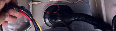
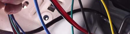
5 5) Pick out a location to mount the WOT Box. The WOT Box must be installed inside the passenger compartment because it is not waterproof. Additionally, you will want to make the WOT Box accessible to the driver. This location under the kick panel works well. Unplug the WOT Box and tape the connector to the mounting location. 6) Carefully poke a new hole in the pass through grommet using a sharp object, such as a screwdriver. Be careful not to damage other wires already in the grommet, and make sure that the hole is only large enough for the WOT Box Wires to pass though. If it is too large, water can leak in. Route all of the WOT Box Wires through the grommet, leaving the WOT Box Connector in the passenger compartment. 6) 5)


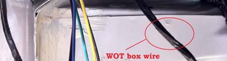


6 7) Under the hood, remove the battery and the tray underneath it. Underneath the battery tray, there s a hole that will fit the 7/16 grommet. Install the grommet and route the WOT Box wires through it. 7)
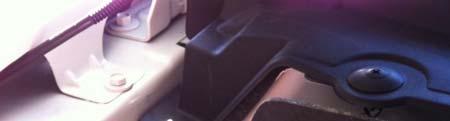
7 8) The PCM is located in the front of the engine compartment on the passenger side. Unplug all 3 camlock connectors from the PCM by unlocking the grey levers and pulling the connectors out. 8)
8 9) Remove enough of the loom behind the T connector (the top one) to access the wires. Splice the GREEN WOT Box Wire into the GREEN/VIOLET wire on pin 21. Use the N2MB recommended soldering technique available at 9) 10) 10) Remove enough of the loom behind the E connector (the middle one) to access the wires. Splice the YELLOW WOT Box Wire into the YELLOW/VIOLET wire on pin 13. Use the N2MB recommended soldering technique available at 11) Remove enough of the loom behind the bottom (B) connector to access the wires. Splice the BLUE WOT Box Wire into the BLUE/WHITE wire on pin 29 of the BOTTOM CONNECTOR. Use the N2MB recommended soldering technique. Re install the loom on all connectors accessed and tape securely with electrical tape. Reattach the connectors to the ECM. 11)
 13) After the cover is removed, the top of the BEC becomes visible.")
9 12) 12) The Bussed Electrical Center is located directly to the passenger side of the PCM. Remove its cover. 13) 13) After the cover is removed, the top of the BEC becomes visible. Hold down the plastic snaps on either side, and remove the top of the BEC to allow access to the wires underneath.
 15) Cut this wire, making sure to leave enough room on either side to make a splice.")
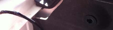
10 14) 14) Underneath the area indicated, find the YELLOW/GREEN wire (it will be connected to Fuse 40, a 15A fuse). 15) 15) Cut this wire, making sure to leave enough room on either side to make a splice. Join the RED WOT Box Wire to the wire end coming from the fusebox, and the ORANGE WOT Box Wire of the RED/ORANGE PAIR to the side wire end leading away from the fusebox. Reassemble the fusebox, and replace the cover. 16) 16) Crimp the included ground lug onto the SINGLE BLACK WOT Box Wire and connect through a bolt to a good body ground. The location on the shock tower shown here works well.

11 17) Ensure that the wires are laying as you would like them to permanently, then replace the wheel well fender liner, the wheel, and the footwell carpet. Ensure that everything that was removed for installation has been replaced besides the 12V battery negative. Insert the WOT Box harness into the WOT Box, reconnect the 12V battery negative, and close the hood. 18) The 2011 Mustang uses a different accelerator pedal position sensor than other mustangs. Download the latest WOT Box graphical user interface available at Connect to the interface and set it up for your vehicle in the manner described on the website. If the TPS section of the Vehicle Snapshot section reads up when the accelerator up and dn with the accelerator down, you re done. If not, you will need to change the TPS threshold in BOTH the Launch Control window and the No Lift Shift window. To do this, ensure that you have the WOT Box connected to the vehicle, change the TPS threshold to 1.7V, click WRITE, and test to determine if the WOT Box reads up or dn in the Vehicle Snapshot section with the accelerator up or down. If the GUI doesn t acknowledge the correct position of the accelerator, note the voltage to the left of the up/dn indicator, and change the TPS threshold until the GUI reads up with the accelerator up and dn with the accelerator down. For most 2011 Mustangs, the TPS Threshold boxes in the GUI should appear like this: 19) Test the WOT Box as described below, and then re install the right passenger side kick panel.
12 Troubleshooting Testing the WOT Box 1. Key on the car but do not start the engine. Press the gas pedal to the floor. You should see the LED on the WOT Box start to rapidly blink. If it does not, check your APP sensor signal connection (WOT Box BLUE wire). 2. Next, with the gas pedal still depressed, press the clutch pedal to the floor. You should see the LED on the WOT Box briefly go out, and then come back on solid for one second and then finally resume blinking rapidly. If you do not see this, check your Clutch Pedal Position Switch signal connection (WOT Box GREEN wire). 3. Next, start the engine. Quickly press the gas pedal to the floor and immediately step on the clutch. You should hear the engine start to rev up, stumble for a short period while the ignition is cut, then return back on and continue revving. Remove your foot from the gas before you hit the rev limiter. The 2 step will not engage if the gas is depressed before the clutch. This is normal. If the engine does not stumble or pause when the LED turns out, then check the RED/ORANGE paired wire. Verify that the RED and ORANGE 16 AWG wires are wired facing the proper way. If they are reversed, the ignition cut will not work. 4. Lastly, test the 2 Step. Press the clutch pedal down and then quickly press the gas pedal all the way down. The gas pedal must be floored for the 2 step to engage. The engine should rev up to the desired RPM and hold. If it does not, be sure to remove your foot from the gas before you hit the rev limiter. If the 2 step does not work, check the WOT Box YELLOW wire. 5. The WOT Box Graphical User Interface has some inherent troubleshooting capability. If you have access to a laptop, it may be useful for you to download the GUI at and follow the instructions there. Usage To use the WOT Shift feature, keep your foot fully on the gas and shift quickly using the clutch. Keep the gas fully depressed through the shift. The WOT Box will detect the clutch switch signal and briefly cut the ignition to enable an effortless shift. To use the 2 Step feature, fully depress the clutch. Next, fully depress the gas pedal to the floor. The engine will rev up and hold the RPM that you have set. Quickly release the clutch while leaving the gas fully depressed to launch the car. CONGRATULATIONS! You have successfully installed the N2MB WOT BOX!
13 N2MB Racing Limited Warranty N2MB Racing warrants that all of its products are free from defects in material and workmanship for a period of 1 year from the date of purchase. If an N2MB product is found to be defective within this period, N2MB Racing will repair or replace the product. The choice between these two methods of remedy is made at the sole discretion of N2MB Racing. This shall constitute the sole remedy of the purchaser and the sole liability of N2MB Racing to the extent permitted by law. This warranty is exclusive and in lieu of all other warranties or representations whether expressed or implied. This warranty is limited to the repair or replacement of the N2MB Racing product, and shall never exceed the purchase price of the N2MB Racing product. N2MB shall not be responsible for special or consequential damage or costs incurred as a result of the failure or use of the N2MB Racing Product except as required by law. Unauthorized alteration or repair of N2MB Racing products will void this warranty if the alteration or repair is found to have caused the N2MB Racing product to fail. In the event that a product is warranted, the purchaser shall be responsible for any and all shipping costs. N2MB Racing reserves the right to improve its products at any time and is at no time responsible for exchange or upgrade of products that were manufactured previously.
Ford Mustang, SVT, Cobra
 1996 2004 Ford Mustang, SVT, Cobra N2MB WOT Box Installation Instructions NOTE: If you have a CDI (capacitive discharge ignition system) please contact us at support@n2mb.com for additional instructions.
WOT Box Installation Instructions Mazda Speed 3
 WOT Box Installation Instructions Mazda Speed 3 Connector Pinout Pin Color AWG Name Description 1 Yellow 18 CKP Connect to Crankshaft Position Sensor 2 Black 18 Ground Connect to chassis ground 3 Black
Signal Mirror Installation Instructions
 Signal Mirror Installation Instructions 2005-2010 Chevy Corvette C6 THE safety accessory of the 21 st Century. P/N 210-0144-0 Rev. A3 (9/29/2011), BTV 2007 Muth Mirror Systems, LLC Page 3 of 10PplPage
Conflicts Note: Drop-in Bed liner
 Toyota Tundra 2015 LED Bed Lights Preparation Part Number: 00016-34089 Accessory Code: BU1000 Conflicts Note: Drop-in Bed liner Kit Contents Item # Quantity Reqd. Description 1 1 Hardware Kit 2 1 Driver
INSTALLATION. Preparation:
 INSTALLATION Preparation: Average Time Required: 2 to 3 hours Place a blanket down in the area which you will be working in. This will prevent scratches on the rear fascia / valance. Remove your License
Signal Mirror Installation Instructions
 Signal Mirror Installation Instructions Honda CRV 1997-2003 THE safety accessory of the 21 st Century. P/N 210-0032-0 Rev B2 (6-26-04), GG 2003 Muth Mirror Systems, LLC. Note: Professional Installation
Signal Mirror Installation Instructions Toyota Tacoma
 Signal Mirror Installation Instructions 2005-2015 Toyota Tacoma THE safety accessory of the 21 st Century. P/N 210-0115-0 Rev. A4 (3/11/15), BTV 2005 Muth Mirror Systems, LLC Page 3 of 12PplPage 3 of 12
LED Cup Holder Lights Installation Guide
 LED Cup Holder Lights Installation Guide (20112015 Kia Optima) Thanks for purchasing this LED Cup Holder Light Kit! If you have any questions or feedback please email us direct at Sales@K5OptimaStore.com
Signal Mirror Installation Instructions
 Signal Mirror Installation Instructions Toyota RAV4 1996-2000 THE safety accessory of the 21 st Century. P/N 210-0034-0 Rev B1 (11-19-02), GG 2002 Muth Co. LLC. Note: Professional Installation Recommended
Bi-Color Signal Mirror Installation Instructions
 Bi-Color Signal Mirror Installation Instructions 2005-2009 Toyota Tacoma THE safety accessory of the 21 st Century. P/N 210-0141-0 Rev. A2 (3/30/09), BTV 2007 Muth Mirror Systems, LLC Page 3 of 13PplPage
Signal Mirror Installation Instructions
 Signal Mirror Installation Instructions Ford Explorer 1996-2001, Ford Explorer SportTrac 2001, Ford Ranger 1996-2001, Mazda B-2500\B-3000\B-4000 1998-2001, Mercury Mountaineer 1997-2001 THE safety accessory
Daytime Running Lights - Splice-in (10-12 All):
:") Time Necessary: Approximately 1 hour Tools Required: Heat Gun Installation Procedure: Daytime Running Lights - Splice-in (10-12 All): 1. It is recommended that the positive terminal be removed from the
Time Necessary: Approximately 1 hour Tools Required: Heat Gun Installation Procedure: Daytime Running Lights - Splice-in (10-12 All): 1. It is recommended that the positive terminal be removed from the
AUDI A8 D3 REPLACING THE OUTSIDE DRIVER DOOR HANDLE
 AUDI A8 D3 REPLACING THE OUTSIDE DRIVER DOOR HANDLE The keyless entry system in the D3 is a great feature. If you have the car key fob in your pocket, putting your hand under the door handle will unlock
Signal Mirror Installation Instructions
 Signal Mirror Installation Instructions 2006 2007 Honda Ridgeline THE safety accessory of the 21 st Century. P/N 210 0142 0 Rev. A (9/5/07), BTV 2007 Muth Company, LLC Professional Installation Recommended:
Commercial Vehicle Productivity and Security. Antenna Configuration. External Antenna Installation (model 6650H only) Contigo 6650H/6651H Beacon
 Contigo 6650H/6651H Beacon") Commercial Vehicle Productivity and Security The 6650H/6651H is a versatile and economical GPS tracking beacon designed for fleet management needs in all commercial vehicles. The H designation in the model
Commercial Vehicle Productivity and Security The 6650H/6651H is a versatile and economical GPS tracking beacon designed for fleet management needs in all commercial vehicles. The H designation in the model
Signal Mirror Installation Instructions Honda Odyssey
 Signal Mirror Installation Instructions 2005-2009 Honda Odyssey THE safety accessory of the 21st Century. P/N 210-0122-0 Rev. A4 (6/9/09), BTV 2006 Muth Company, LLC PROFESSIONAL INSTALLATION RECOMMENDED
Signal Mirror Installation Instructions
 Signal Mirror Installation Instructions 2004 2008 Ford F-150 XLT, FX4, & Lariat Pre-wired without side signals Pre-wired with side signals Without side directional lights, see page 2 With side directional
Signal Mirror Installation Instructions Dodge Charger, Dodge Magnum, Chrysler 300
 Signal Mirror Installation Instructions 2006-2009 Dodge Charger, 2005-2008 Dodge Magnum, 2005-2009 Chrysler 300 THE safety accessory of the 21st Century. P/N 210-0123-0 Rev. A4 (10/7/09), BTV 2007 Muth
05-17 Mustang Fuel System Wire Upgrade Installation
 PARTS LIST: -10AWG INLINE FUSE HOLDER WITH 30AMP BLADE FUSE -16FT 10AWG HIGH CURRENT PRIMARY WIRE -40AMP AUTOMOTIVE RELAY -1FT 10AWG GROUND WIRE -1FT 10AWG HIGH CURRENT PRIMARY WIRE OUTPUT TO FPDM -1FT
Cover Page. Factory Radio Other Documents Available For This Vehicle:
 Factory Radio Other Documents Available For This Vehicle: No documents available at this time Adobe Acrobat Reader Printing Tips: 1) Select FLE then PRNT and select your printer. 2) n the print options
Installation instructions, accessories. TV receiver, digital
 Installation instructions, accessories Instruction No 30756561 Version 1.1 5 Part. No. 30756181, 30756569 TV receiver, digital Volvo Car Corporation TV receiver, digital- 30756561 - V1.1 Page 1 / 36 Equipment
IMPORTANT WARRANTY & INSTALLATION INSTRUCTIONS ATTACHED
 IMPORTANT WARRANTY & INSTALLATION INSTRUCTIONS ATTACHED Please Forward All Attached Information to Consumer Warranty Not Valid Unless Returned to Volant Performance STOP Please be sure to review the enclosed
* * APPLICABLE MODELS: 2014 > MAZDA 3
 PART NUMBER: 0000 8C L46 GENUINE ACCESSORIES INSTALLATION INSTRUCTIONS Rev. AAA *550-0604-000* APPLICABLE MODELS: 204 > MAZDA 3 REQUIRED COMPONENTS: ITEM QTY DESCRIPTION Usage Chart MIRROR ASSEMBLY: Mirror
Installation Manual Roof Zone Ladder Rack
 Installation Manual Roof Zone Ladder Rack 102113,E1346 Installation Time: About 90 minutes. Depending on truck and Do-it-Yourself experience level Tools Required: Electric Drill with 1/2 Chuck 1/2 & 7/32
BrewsBySmith.com STC DIY Kit
 BrewsBySmith.com STC-1000 + DIY Kit Contact Information: Greg Smith www.brewsbysmith.com greg@boostbysmith.com I. Hardware Included: STC-1000 flashed with latest software (v1.06 currently) (if purchased)
TOYOTA TACOMA LED BED LIGHTS Preparation
 Preparation Part Number: PT948-35160 Kit Contents Item # Quantity Reqd. Description 1 1 Hardware Kit 2 1 Driver Side LED assembly 3 1 Passenger Side LED assembly 4 1 Main Wire Harness Hardware Bag Contents
RAZOR. Class D Full Range & Monoblock Amplifiers RZ4-1200D RZ4-2000D RZ1-1500D RZ1-2300D
 RAZOR Class D Full Range & Monoblock Amplifiers RZ4-1200D RZ4-2000D RZ1-1500D RZ1-2300D WWW.POWERACOUSTIK.COM 4 Channel RZ4-1200D & RZ4-2000D Full MOSFET PWM Power Supply SMD Technology on Double Sided
Installation Procedures Dodge Charger R/T Scat Pak, SRT/Hellcat. SNS 66a
 Installation Procedures 2015-2017 Dodge Charger R/T Scat Pak, SRT/Hellcat SNS 66a Warning: Please read directions completely before starting. If you have any questions please contact BMPP before beginning
I Click on a link tab to jump to that page. Cover Page
 Publication, Duplication, or Retransmission Of This Document Not Expressly Authorized n Writing By The nstall Doctor s Prohibited. Protected By U.S. Copyright Laws. 1997,1998,1999,2000. Factory Radio Other
GEN II Toyota Prius Back Door Opener Switch Replacement & License Plate Lights
 GEN II Toyota Prius Back Door Opener Switch Replacement & License Plate Lights Rubber Surface of Switch had Degraded to Tar-like Substance Vehicle Manufacture Date 10/06 OLD SWITCH IN GARNISH SWITCH REMOVED
GENUINE ACCESSORIES INSTALLATION INSTRUCTIONS. ITEM QTY DESCRIPTION Usage Chart
 PART NUMBER: 0000 8C R0 GENUINE ACCESSORIES INSTALLATION INSTRUCTIONS Rev. AAA *550-0554-000* APPLICABLE MODELS: 203 > CX-5 REQUIRED COMPONENTS: ITEM QTY DESCRIPTION Usage Chart MIRROR ASSEMBLY: Mirror
Repairing your Porsche 928 Central Warning System (CWS) controller
 controller") Repairing your Porsche 928 Central Warning System (CWS) controller Disclaimer: This procedure is for a 1984 Porsche 928 S controller. Overview: Under the left foot pedal (dead pedal) of the Porsche 928
Repairing your Porsche 928 Central Warning System (CWS) controller Disclaimer: This procedure is for a 1984 Porsche 928 S controller. Overview: Under the left foot pedal (dead pedal) of the Porsche 928
Installation Procedures For Corvette Basic/C-6 SNS 28
 Installation Procedures For 2005-2013 Corvette Basic/C-6 SNS 28 Warning: Please read directions completely before starting. If you have any questions please contact BMPP before beginning your installation.
Installation Procedures 2015 Corvette C-7 Z06 With Carbon Fiber Kit SNS 50a
 Installation Procedures 2015 Corvette C-7 Z06 With Carbon Fiber Kit SNS 50a Warning: Please read directions completely before starting. If you have any questions please contact BMPP before beginning your
Sea Doo Spark Engine Access Kit
 Sea Doo Spark Engine Access Kit PART# - RS4-130-EAK APPLICATION(S): Sea Doo Spark. 2up & 3up Models. We strongly recommend the use of a service manual to familiarize yourself with the various components
(WD) Dodge Durango (WK) Jeep Grand Cherokee
 Dodge Durango (WK) Jeep Grand Cherokee") Dealer Service Instructions for: Safety Recall R09 / NHTSA 15V-115 Fuel Pump Relay Models 2012-2013 (WD) Dodge Durango (WK) Jeep Grand Cherokee July 2015 IMPORTANT: Many of the vehicles within the above
Dealer Service Instructions for: Safety Recall R09 / NHTSA 15V-115 Fuel Pump Relay Models 2012-2013 (WD) Dodge Durango (WK) Jeep Grand Cherokee July 2015 IMPORTANT: Many of the vehicles within the above
Installation Procedures 2015 Roush Mustang Stage 1 & 2. SNS 62b
 Installation Procedures 2015 Roush Mustang Stage 1 & 2 SNS 62b Warning: Please read directions completely before starting. If you have any questions please contact BMPP before beginning your installation.
Harmony Remote Repair
 Harmony Remote Repair harmonyremoterepair.com How to install your new Harmony One Front Cover/Touch Screen Important! Before you begin working on your Harmony One, you must discharge any static electricity
Signal Mirror Installation Instructions
 Signal Mirror Installation Instructions Pontiac Grand Prix 1997-2003; Sedan and oupe THE safety accessory of the 21st entury. P/N 210-0018-0 Rev 2 (6-24-04), GG 2002 Muth Mirror Systems, LL. Note: Professional
Installation Procedures For 2013 Mustang V-6 and 5.0
 Installation Procedures For 2013 Mustang V-6 and 5.0 Warning: Please read directions completely before starting. If you have any questions please contact BMPP before beginning your installation.. Also
Install The Trailer Lighting Wire Harness Connector
 Install The Trailer Lighting Wire Harness Connector This is probably the toughest part of the whole trailer hitch install. It helps to have a little background in electronics, but if you don't then simply
Installation tutorial for Console Customs Xbox ONE MaxFire ONE V2 PCB
 Installation tutorial for Console Customs Xbox ONE MaxFire ONE V2 PCB This tutorial is designed to aid you in installation of a console customs MaxFire ONE V2 Circuit board in the newer Xbox One Controllers
Installation Instructions Dual battery Tray Wrangler & Unlimited Part # 2799
 Please read instructions entirely before installing this product. Wiring is not included with this part and should be done by an experienced technician. This part is designed to work with Optima Class
1997 I Click on a link tab to jump to that page. Cover Page
 & nstall Publication, Duplication, or Retransmission Of This Document Not Expressly Authorized n Writing By The nstall Doctor s Prohibited. Protected By U.S. Copyright Laws.,1998,1999,2000. Factory Radio
Installation Procedures 2018 Mustang GT & EcoBoost SNS 135
 Installation Procedures 2018 Mustang GT & EcoBoost SNS 135 Warning: Please read directions completely before starting. If you have any questions, please contact BMPP before beginning your installation.
TOYOTA TACOMA TRAILER WIRE HARNESS Preparation
 Preparation Part Number: PT725-35120 Kit Contents Item Quantity Reqd. Description # 1 1 Flasher Assembly (F/A) 2 1 Wire Harness 3 1 Sub Wire Harness 4 2 Plastic Tie (300mm) 5 4 Plastic Tie (200mm) 6 13
Trailer Receiver Hitch Installation Instructions
 Model/Application: 1006: 10-15 R60 Countryman 10-15 R60 Countryman S 11-xx R61 Paceman 11-xx R61 Paceman S Hitch Capacity: 2000 lbs gross, 200 lb. max tongue Notes: This hitch allows for a removable ball
SSI-4 PLUS User Manual
 SSI-4 PLUS User Manual 1 SSI-4 PLUS... 2 1.1 Getting to Know the SSI-4 PLUS... 2 1.2 Channel Functions... 3 2 Wiring and Setup... 3 2.1 Powering the SSI-4 PLUS... 3 2.2 5V for External Sensors... 4 2.3
RV 10 Interior Panels
 RV 10 Interior Panels Important Notice: This manual contains important information that may affect the safety of your aircraft. Read the Warranty / Agreement below. There is information in the Warranty
TOOLS REQUIRED FOR INSTALLATION: AIR RACHET, GRINDER AND CUTTER.
 THIS KIT INCLUDES: 16 M8-1.25X30MM BOLTS WITH WASHERS 2 SHOCKS 565 PSI RIGHT AND LEFT HINGE ASSEMBLY 2 SHOULDER BOLTS 2 PINS TOOLS REQUIRED FOR INSTALLATION: AIR RACHET, GRINDER AND CUTTER. 7/23, 10MM,
NEO CAR AUDIO. Neo AUXiN AUX INPUT INTERFACE. Instruction Manual
 NEO CAR AUDIO Neo AUXiN AUX INPUT INTERFACE Instruction Manual IMPORTANT NOTE Neo AUXiN Dip switch positions MUST be set BEFORE any other step is taken. Otherwise, the kit will not operate properly. See
Installation Procedures Maserati Gran Turismo Sport SNS 85
 Installation Procedures 2012-2017 Maserati Gran Turismo Sport SNS 85 Warning: Please read directions completely before starting. If you have any questions please contact BMPP before beginning your installation.
Iphone 5 Glass/Lcd REPAIR GUIDE. Version Edition
 Iphone 5 Glass/Lcd REPAIR GUIDE Version 1 2016 Edition IPhone 5 Glass/LCd REPAIR GUIDE RiAna Soto Repair Training Specialist rsoto@cellairis.com FOR EVERY REPAIR MAKE SURE TO COMPLETE, INITIAL, AND HAVE
MM Strut Tower Brace, Cobra (MMSTB-7)
") The MM strut Tower Brace attaches to each strut tower and to the firewall. 3430 Sacramento Dr., Unit D San Luis Obispo, CA 93401 Telephone: 805/544-8748 Fax: 805/544-8645 www.maximummotorsports.com MM
The MM strut Tower Brace attaches to each strut tower and to the firewall. 3430 Sacramento Dr., Unit D San Luis Obispo, CA 93401 Telephone: 805/544-8748 Fax: 805/544-8645 www.maximummotorsports.com MM
Wildcat XX Stage 1 Audio Kit
 2436-466 Wildcat XX Stage 1 Audio Kit WARRANTY INFORMATION: All SSV Works enclosures are covered by a limited lifetime warranty against defects in material or workmanship. All SSV Works Electronics are
I Click on a link tab to jump to that page. Cover Page
 Factory Radio Other Documents Available For This Vehicle: No documents available at this time Adobe Acrobat Reader Printing Tips: 1) Select FLE then PRNT and select your printer. 2) n the print options
BX2173 Installation Instructions Ford Focus (including the 2.3L engine) 2003 Ford Focus SVT
 2003 Ford Focus SVT") BX2173 Installation Instructions 2000-04 Ford Focus (including the 2.3L engine) 2003 Ford Focus SVT Serial No. The front fascia, coolant line bracket and anti-pollution devices are removed for baseplate
BX2173 Installation Instructions 2000-04 Ford Focus (including the 2.3L engine) 2003 Ford Focus SVT Serial No. The front fascia, coolant line bracket and anti-pollution devices are removed for baseplate
Please read BOTH these Installation Instructions and the General Instructions prior to installing or operating this equipment.
 Attachment Tab Height: 13 Attachment Tab Width: 24 Please read BOTH these and the General Instructions prior to installing or operating this equipment. Serial Number 1. Blue Ox towing products and accessories
Fletcher F-3000 / F-3100 Accessory Laser Kit
 Fletcher F-3000 / F-3100 Accessory Laser Kit Shown Assembled on F-3000 Machine Product Warranty The Fletcher-Terry Company warrants the product purchased to be free from defects in parts and workmanship
WARNING. Bolt Torque Specifications Torque in Foot-Pounds for Inch Bolts Bolt Size Grade 5 Grade 8
 1. Blue Ox towing products and accessories are intended to be installed by Blue Ox Dealers who are familiar with our products and have the equipment and knowledge necessary to do fit work. If needed, Blue
Installation Procedures Jaguar XF SNS 92
 Installation Procedures 2016-2017 Jaguar XF SNS 92 Warning: Please read directions completely before starting. If you have any questions please contact BMPP before beginning your installation. Also please
WARNING. Bolt Torque Specifications Torque in Foot-Pounds for Inch Bolts Bolt Size Grade 5 Grade 8
 1. Blue Ox towing products and accessories are intended to be installed by Blue Ox Dealers who are familiar with our products and have the equipment and knowledge necessary to do fit work. If needed, Blue
WARNING. BX Ford Explorer With Adaptive Cruise Control & Eco Boost Installation Instructions
 Please read BOTH these and the General Instructions before attempting to install or operate this equipment. 1. Blue Ox towing products and accessories are intended to be installed by Blue Ox Dealers who
IMPORTANT WARRANTY & INSTALLATION INSTRUCTIONS ATTACHED
 IMPORTANT WARRANTY & INSTALLATION INSTRUCTIONS ATTACHED Please Forward All Attached Information to Consumer Warranty Not Valid Unless Returned to Volant Performance For Full-Color Installation Instructions,
Instructions for Lighting an S Scale Caboose
 Instructions for Lighting an S Scale Caboose The S Scale Caboose lighting kit is adaptable for most caboose models of rolling stock including American Flyer (TM) and contains the same components as found
I Click on a link tab to jump to that page. Cover Page
 Publication, Duplication, or Retransmission Of This Document Not Expressly Authorized n Writing By The nstall Doctor s Prohibited. Protected By U.S. Copyright Laws. 1997,1998,1999,2000. & nstall Factory
Steele TV Stand Stock # BH
 LOT NUMBER: DATE PURCHASED: / / Steele TV Stand Stock # BH46-084-899-02 ADULT ASSEMBLY REQUIRED If you have any questions regarding assembly or if parts are missing, DO NOT return this item to the store
WARNING. Serial Number. BX Ford Taurus With Adaptive Cruise Control Installation Instructions
 Serial Number BX2629 Please read BOTH these and the General Towing Instructions before attempting to install or operate this equipment. 1. Blue Ox towing products and accessories are intended to be installed
PAC-12 Kit Contents. Tools Needed Soldering iron Phillips screwdriver Wire stripper Wrenches, 7/16 and 1/2 Terminal crimp tool Pliers Solder
 PAC-2 Kit Contents Part Quantity Screws: 8/32 x 3/8 Screws: 8-32 x 5/6 Screw: 8-32 x /4 #8 internal tooth washers #8 solder lug ring terminals Bolt: Aluminum, /4-20 x.5 /4 internal tooth washer Nut: Aluminum
Arsenal One Install Instructions for Xbox One Controller
 Arsenal One Install Instructions for Xbox One Controller arsenalmod.com Page 1 of 14 Before Proceeding These instructions are for the install of the Arsenal One 28 pin chip for the Xbox One. READ ALL INSTRUCTIONS
TOYOTA TACOMA 2005 TRAILER WIRE HARNESS Preparation
 Preparation Part Number: 08921 04960 NOTE: Part number of this accessory may not be the same as the part number shown. Kit Contents Item # Quantity Reqd. Description 1 1 Converter Assembl y 2 1 Wire Harness
BX Honda Accord Ex-L 2012 Honda Accord SE Installation Instructions
 Please read BOTH these and the General Instructions before attempting to install or operate this equipment. Serial Number 1. Blue Ox towing products and accessories are intended to be installed by Blue
Installation Procedures Dodge Challenger SXT, R/T, Scat Pak, SRT & Hellcat SNS 1a
 Installation Procedures 2015-2017 Dodge Challenger SXT, R/T, Scat Pak, SRT & Hellcat SNS 1a Warning: Please read directions completely before starting. If you have any questions, please contact BMPP before
IMPORTANT WARRANTY & INSTALLATION INSTRUCTIONS ATTACHED
 IMPORTANT WARRANTY & INSTALLATION INSTRUCTIONS ATTACHED Please Forward All Attached Information to Consumer Warranty Not Valid Unless Returned to Volant Performance STOP Please be sure to review the enclosed
3 Shielded Compact Ribbon (SCR) Wiremount Plug, XX, and Shell Kit, F200-XXX
 Wiremount Plug, XX, and Shell Kit, F200-XXX") 3 Shielded Compact Ribbon (SCR) Wiremount Plug, 36110-3000XX, and Shell Kit, 36310-F200-XXX Instructions June 2007 78-9100-4282-5 General This instruction manual explains the method of assembling the 3M
3 Shielded Compact Ribbon (SCR) Wiremount Plug, 36110-3000XX, and Shell Kit, 36310-F200-XXX Instructions June 2007 78-9100-4282-5 General This instruction manual explains the method of assembling the 3M
CORVETTE CORVETTE REV: Made in USA U.S. PATENT #6,808,223; #6,845,547; #7,140,075; #7,059,655 and other patents pending.
 CORVETTE 2005-2006 CORVETTE 2005-2007 REV: 7-2-07 Made in USA U.S. PATENT #6,808,223; #6,845,547; #7,140,075; #7,059,655 and other patents pending. Page 1 of 12 CORVETTE C6 2005-2007 THIS KIT INCLUDES:
Please read BOTH these Installation Instructions and the General Instructions prior to installing or operating this equipment.
 2012-14 Chevy Captiva Sport Attachment Tab Height: 21-1/2 Serial Number Attachment Tab Width: 18-1/2 Please read BOTH these and the General Instructions prior to installing or operating this equipment.
A3 Jetta TDI Chip Upgrade
 A3 Jetta TDI Chip Upgrade View the online version at http://vw.ogdenlabs.com/kerma.htm I'm writing this article to show how to go about upgrading an A3 Jetta TDI. Please be aware that this is for information
ASPEN OUTDOOR TABLE TENNIS
 ASPEN OUTDOOR TABLE TENNIS Replacement Parts Order direct at or call our Customer Service department at (800) 225-7593 8 am to :30 pm Central Standard Time January 201 UPC Code 7-19265-51830-3 Staple your
Application Note. Bowser-Stewart VO-1000 Tsunami Digital Sound Decoder Installation Notes
 Application Note Overview This application note describes how to install a TSU-1000 Digital Sound Decoder into the Bowser-Stewart VO-1000 Locomotive. Skill Level 4: The entire installation can be completed
INSTALLATION INSTRUCTIONS for DALTON LED SERIES
 WINSCAPE INSTALLATION INSTRUCTIONS for DALTON LED SERIES These instructions cover the installation for the following fixtures & options: - Dalton LED (DALED, DABRLED) series - Any Modified or Custom fixture
I Click on a link tab to jump to that page. Cover Page
 Publication, Duplication, or Retransmission Of This Document Not Expressly Authorized n Writing By The nstall Doctor s Prohibited. Protected By U.S. Copyright Laws. 1997,,1999,2000. & nstall Factory Radio
1104. Clean up the door striker plates with a hand grinder using a wire brush and WD-40.
 Chapter 31 - Misc. Putting VW Back Together (Video Clip 31) 1104. Clean up the door striker plates with a hand grinder using a wire brush and WD-40. 1105. Install both door striker plates on the VW body
Please read BOTH these Installation Instructions and the General Instructions prior to installing or operating this equipment.
 Serial Number BX3620 Please read BOTH these and the General Instructions prior to installing or operating this equipment. 1. Blue Ox towing products and accessories are intended to be installed by Blue
unit 3: GENErAL ElectriCAL SySTEM DiAGNOSiS
 Electrical/Electronic Systems unit 3: GENErAL ElectriCAL SySTEM DiAGNOSiS lesson 4: wire and connector repairs I. Connector repairs A. Connector repairs involve fixing damaged wires. Wires are marred due
F-Series Trucks - Ford Full Size Bronco - Ford
 & nstall Publication, Duplication, or Retransmission Of This Document Not Expressly Authorized n Writing By The nstall Doctor s Prohibited. Protected By U.S. Copyright Laws. 1997,1998,1999,2000. Factory
CORVETTE Page 1 of 12 CORVETTE C
 CORVETTE 2005-2006 Page 1 of 12 CORVETTE C5 1997-2004 THIS KIT INCLUDES: 8 M8-1.25X40MM BOLTS WITH WASHERS 8 M8-1.25X30MM BOLTS WITH WASHERS RIGHT AND LEFT HINGE ASSEMBLY WIRE LOOM 2 SHOCKS 565 PSI 2 SHOULDER
WARNING!! DO NOT LIFT DOORS UP WHEN THE HOOD IS OPEN. THE DOORS WILL HIT THE HOOD!
 WARNING!! DO NOT LIFT DOORS UP WHEN THE HOOD IS OPEN. THE DOORS WILL HIT THE HOOD! THIS KIT INCLUDES: 4 M8-1.25X30MM BOLTS WITH WASHERS 12 M8-1.25X40MM BOLTS WITH WASHERS 2 SHOULDER BOLTS WITH RIGHT AND
AutoThrow for A&D by Adam MacDonald
 AutoThrow for A&D by Adam MacDonald Instructions for setup and operation For A&D FX-120i / 200i / 300i October 2017 Find updated documentation at autotrickler.com Parts AutoThrow Hopper Straws (3) Roof
Please read BOTH these Installation Instructions and the General Instructions prior to installing or operating this equipment.
 Attachment Tab Height: 16-1/2 Serial Number Attachment Tab Width: 24 Please read BOTH these and the General Instructions prior to installing or operating this equipment. 1. Blue Ox towing products and
Page 1 of 18. SunRail System Installation Instructions
 Page 1 of 18 SunRail System Installation Instructions Page 2 of 18 SunRail Stainless Steel Railing Installation Guide Table of Contents Before You Begin 3 Installing Surface Mount Bases for a Two Rail
OPERATORS MANUAL WEEKENDER STEEL LADDER RACK
 OPERATORS MANUAL WEEKENDER STEEL LADDER RACK WWW.WEATHERGUARD.COM MODELS 1450 & 1475 1475 Shown INSTALLATION TIME Approximate installation time: 60 minutes (depending on truck equipment installation experience
Scorpion HX User Manual R/C Version
 Table of Contents Features...3 Connections...5 Setup...5 Setup Complete...10 Status Codes...11 Mounting your Scorpion...12 Notes on PCM radios...12 Service and Support...13 Limitations and Warrantees...13
WARNING VW Jetta New Installation Instructions BX3823. Serial Number
 Please read BOTH these and the General Instructions before attempting to install or operate this equipment. Serial Number 1. Blue Ox towing products and accessories are intended to be installed by Blue
BRIDGEABLE FOUR-CHANNEL POWER AMPLIFIER GM-A6604 GM-A4604. Owner s Manual
 BRIDGEABLE FOUR-CHANNEL POWER AMPLIFIER GM-A6604 GM-A4604 Owner s Manual Section 01 Before you start Thank you for purchasing this PIONEER product To ensure proper use, please read through this manual
SAFETY THIS PRODUCT IS FOR OFFROAD USE ONLY. ALL LIABILITY FOR INSTALLATION AND USE RESTS WITH THE OWNER.
 SAFETY Your safety and the safety of others is very important. In order to help you make informed decisions about safety, we have provided installation instructions and other information. These instructions
IMPORTANT WARRANTY & INSTALLATION INSTRUCTIONS ATTACHED
 IMPORTANT WARRANTY & INSTALLATION INSTRUCTIONS ATTACHED Please Forward All Attached Information to Consumer Warranty Not Valid Unless Returned to Volant Performance STOP For Full-Color Installation Instructions
Elite Series Fender Flares
 Page 1 of 8 Installation Instructions I - Sheet Number I606RPG Rev.B Important Safety Information Tools Required Contents Elite Series Fender Flares Preparation Before Painting / Installation NOTE Actual
Installation Instructions Road King Classic Saddlebag Bezels
 Installation Instructions Road King Classic Saddlebag Bezels Thank you for your purchase of Bagger Audio Road King Classic Saddlebag Bezels for your Harley-Davidson motorcycle. We have carefully engineered
Ready-To-Assemble VersaRail INSTALLATION INSTRUCTIONS
 Ready-To-Assemble VersaRail INSTALLATION INSTRUCTIONS Read all instructions prior to installing product. Refer to manufacturers safety instructions when operating any tools. To register your product, please