QUALITY CONTROL INSTRUCTIONS
|
|
|
- Kevin Jones
- 6 years ago
- Views:
Transcription
1 QUALITY CONTROL INSTRUCTIONS QCI NO. 100 REVISION E SPC PROCEDURE WRITTEN BY: R. Zielinski DATE: 2/3/92 APPROVED BY: APPROVED BY: Department Manager Quality Assurance Manager DATE: DATE: SF 118 1
2 CHANGE RECORD Rev. Description A Changed the ten to seven in paragraph 3.4 RCZ RCZ 3/16/92 3/16/92 Written By Approved By Date Effectivity Date Approved By Date Rev. Description B Added to include use of SQC computer data storage and capability analysis, also revised control chart format (Attachments 1 and 2). Expanded section 4.0 to include specific steps to set up attribute control charts. DTN RCZ 10/18/96 10/21/96 Written By Approved By Date Effectivity Date Approved By Date Rev. Description C Added to include designation of variable and attribute charts. Charles Rottner Ray Zielinski 11/28/01 12/3/01 Written By Approved By Date Effectivity Date Mark Lesinski 12/3/01 Approved By Date Rev. Description D Change Production Control to Manufacturing Engineering throughout, Modify paragraphs 2.4.2, 4.1.7, Add paragraph 6.3 Charles Rottner Ray Zielinski 8/24/04 8/25/04 Written By Approved By Date Effectivity Date Mark Lesinski 8/25/04 Approved By Date Rev. Description E Added following statement to para Unless specified by customer drawing or purchase order SVT will require a process capability (CPK) Charles Rottner Michael Elhage 8/11/08 8/13/08 Written By Approved By Date Effectivity Date Approved By Date 2
3 1.0 SCOPE 1.1 This procedure covers implementation and maintenance of Statistical Process Control (SPC) in the manufacturing areas of Servotronics, Inc. 2.0 GENERAL REQUIREMENTS 2.1 Production hardware is subject to SPC charting The use of variable charts is the preferred method of SPC charting. Variable charts will be designated on the operation sheet with a stamp of SPC-V and attribute charts will be designated on the operation sheet with a stamp of SPC-A Unless otherwise specified, charting of variables data refers to the use of Individual and Range (Individual X, Moving R) charts. Ref. SF Attribute control charts (p,np,c,and u charts) will be utilized when charting attribute data and specified where appropriate. Ref. SF All lot sizes are subject to SPC and the requirements contained herein. 2.3 All chart header information must be completed prior to running the setup part Charting that is initiated on one shift will be continued by subsequent shifts where appropriate. 2.4 Dimensional characteristics under SPC control will specified on the operation sheets or other appropriate documentation. This determination will be made by Engineering, Quality, and Manufacturing as a team Each dimensional characteristic under SPC control shall have it s own chart When a control chart is completed, it shall be submitted to Manufacturing Engineering where the data will be entered into the SPC XL2000 or Mini-Tab computer file. A capability analysis will then be performed on the data. Unless specified by customer drawing or purchase order SVT will require a process capability (CPK) FREQUENCIES AND CORRECTIVE ACTION 3.1 Unless otherwise specified, the following general rules apply to Individual and Range variables control charts. 3
4 3.1.1 The following rules do not supersede Servotronics requirement to produce quality hardware. It is everyone s responsibility to strive to attain 100% quality in the components being produced and the processes being performed. Not only must the characteristic selected for SPC control be maintained, but all other requirements, whether specified by drawing or process documentation, must also be within the requirements of the documentation package. This is the responsibility of everyone involved in the process. 3.2 Except as noted, the number or frequency of parts to be charted will be in accordance with lot sizes and Table I. The sample sizes in Table I include the first and last part in each lot that must be charted. Setup parts shall be charted on a separate control chart. The lot run shall be considered to start when all dimensional characteristics are achieved and charting shall be in accordance with Table I When a sample frequency other than every part is used and an out-ofcontrol condition arises, plot every subsequent part until 5 consecutive parts are plotted in control The control limits (UCLX, LCLX, and UCLR) are to be obtained from the drawing and data package supplied. 3.3 If an individual or range data point is outside the control limit(s), the following action must be taken: If the operator can solve the problem the appropriate adjustments shall be made and the corrective action documented on the control chart If an operator can not solve the problem, they shall notify their supervisor If the supervisor can solve the problem the appropriate adjustments shall be made and the corrective action taken documented on the control chart If the supervisor can not solve the problem Quality, Engineering and Manufacturing Engineering shall be notified. The problem shall be addressed and the appropriate action taken to correct the problem. All corrective action taken shall be documented on the control chart. When additional documentation is required it shall be referenced on the control chart. If the problem can not be solved within a reasonable amount of time (normally one shift), the Manufacturing Manager shall be notified. 4
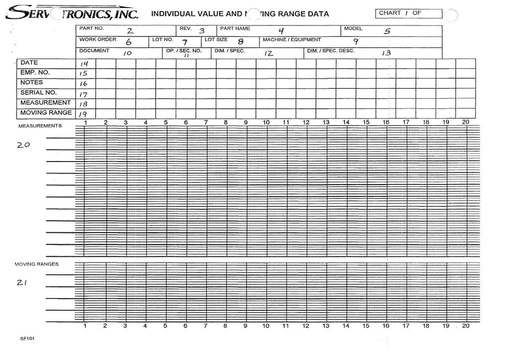
5 3.4 If seven consecutive data points are trending in the same direction, the following action must be taken: Proceed in accordance with through CONTROL CHART SETUP 4.1 The chart header shall be filled out as follows (Ref. SF161 and SF162, attached). When additional chart pages are required, only the entries marked * need be entered in the header Chart No. (1) * Enter chart numbers: 1 of -, 2 of -, 3 of -, etc Part No. (2) * Enter part number from data package Rev. (3) * Enter part revision letter from data package Part Name (4) Enter part name from data package Model (5) Enter model number, if provided, from data package Work Order (6) * Enter work order number from data package Deleted, no longer used due to Pro-Man System Lot Size (8) * Enter number of parts to be produced per the data package. 5
6 4.1.9 Machine / Equipment (9) Enter machine description or test equipment used. e.g. MTC2, MOOG, Test Stand #, etc Document (10) * Enter document that references feature under SPC control. e.g. Op Sheets, EIs, etc Op. / Sec. No. (11) * Enter operation number or section number (para. no.) under SPC control from data package Dim. / Spec. (12) * Enter dimension or specification and tolerance under SPC control from data package Dim. / Spec. Description (13) * Enter brief dimension or specification description: I.D., O.D., hole, current, stroke, etc Date (14) Enter date. If operation spans one or more days, enter next date above and in line with the S/N box for the piece started on that day Employee No. (15) Enter operator employee number Notes (16) Enter sequential number for note pertinent to piece being run. Enter note reference number and note in appropriate locations on the back of the chart. NOTE: Paragraphs are for IX-MR charts only. 6
7 Serial No. (17) Enter the sequential number for the piece being produced. If a large lot is being run, enter the sample sequence number as defined in Table I - 1, 2, 4, 6; 1, 5, 10, 15 etc Measurements (18) Enter the actual dimension or performance parameter that is measured for each part:.0940,.0942,.0938, etc Moving Ranges (19) In the space provided enter the difference between each measurement and the preceding one. The first entry must be zero since a preceding measurement is not available. e.g. (19) (20) Measurement Plot (20) Establish an appropriate scale on the chart so the required information can be adequately plotted. Upper control limits (UCLx) and lower control limits (LCLx) should be established and labeled on the left side of the chart. A line from the left to the right side of the chart should be drawn to signify these limits. These limits should be placed on the chart by Manufacturing Engineering before parts are produced. Control limits are established by recording the first 20 consecutive measurements and giving them to Manufacturing Engineering to be entered into the computer software to be calculated. Use the control limits from the previous run as a reference point to achieve continuous improvement. Plot the actual measurement values (18) on the chart. Place a point on the chart at the intersection of the measured value (horizontal line) and the corresponding measurement sequence number (vertical line). Connect the points using straight lines Moving Range Plot (21) Establish an appropriate scale on the chart so the required information can be adequately plotted (minimum value of the moving range). 7
8 The upper control limit (UCLR) should be located and label on the left side of the chart. A line from the left to the right side of the chart should be drawn to signify this limit. This limit should be placed on the chart by Manufacturing Engineering before parts are produced. Plot the calculated moving range points on the chart. Place a point on the chart at the intersection of the moving range value (horizontal line) and the corresponding measurement sequence number (vertical line). Connect the points using straight lines. NOTE: Paragraphs are for attribute charts only Sample Size (22) Enter the number of parts chosen per sample No. Defects (23) Enter the number of defects found within the sample size (22) Chart Type (24) Enter type of attribute chart that will be utilized for SPC control of this feature (p, np, c, u). This should be entered by Manufacturing Engineering Attribute Plot (25) Establish an appropriate scale on the chart so the required information can be adequately plotted. Appropriate upper and lower control limits (UCL and LCL) should be established and labeled on the left side of the chart. A line from the left to the right side of the chart should be drawn to signify these limits. These limits should be placed on the chart by Manufacturing Engineering before parts are produced. Plot the appropriate non-conformance ratio (dependent on sample size (22), number of defects per sample (23), and chart type (24)) on the chart. Place a point on the chart at the intersection of the measured value (horizontal line) and the corresponding measurement sequence number (vertical line). Connect the points using straight lines. 5.0 IDENTIFICATION 5.1 Charted parts will be marked for identification. 8
9 5.1.1 Enter the applicable operation / section number and the number that corresponds with the measurement of that part. e.g. Op. 30 / Subsequent operations which are under SPC control can be added to the bag or tag. Number on tags or bags for different operations are independent from one another. e.g. Chart number 10 from one operation does not need to be number 10 when the hardware is started at the next operation. The component must retain the identification throughout the manufacturing process. This identification must be present when the components are submitted for final inspection. 6.0 FINAL INSPECTION 6.1 Move lot to final inspection for verification. 6.2 Verify lot per requirements of Q.C.I Store completed control charts with attached computer generated capability analysis in Quality Assurance 9
10 TABLE I (Reference Para. 3.2) LOT SIZE FREQUENCY I Every part charted II Every other part charted III Every fifth part charted IV. 200 and up Every tenth part charted 10
11 11
12 12
13 13
ANALYZE. Lean Six Sigma Black Belt. Chapter 2-3. Short Run SPC Institute of Industrial Engineers 2-3-1
 Chapter 2-3 Short Run SPC 2-3-1 Consider the Following Low production quantity One process produces many different items Different operators use the same equipment These are all what we refer to as short
PS901500E IDENTIFICATION, MARKING, HANDLING, PROCESSING AND INSPECTION OF CRITICAL PARTS
 SECURITY CLASS: UNCLASSIFIED COML. CLASS: UNCLASSIFIED DOCUMENT IDENTIFIER SUBJECT: IDENTIFICATION, MARKING, HANDLING, PROCESSING AND INSPECTION OF CRITICAL PARTS MATERIAL ENGINEERING & TECHNOLOGY DEVELOPMENT
Engineering Drawing System
 LPR 7320.1 Effective Date: February 2, 2010 Expiration Date: February 2, 2015 Langley Research Center Engineering Drawing System National Aeronautics and Space Administration Responsible Office: Systems
Engineering Drawing System
 LPR 7320.1 Effective Date: July 18, 2004 Expiration Date: July 18, 2008 Langley Research Center Engineering Drawing System National Aeronautics and Space Administration Responsible Office: Systems Engineering
JEFFERSON LAB TECHNICAL ENGINEERING & DEVELOPMENT FACILITY (TEDF ONE) Newport News, Virginia
 Newport News, Virginia") BULLETIN NO. 6 TO THE PLANS AND SPECIFICATIONS FOR JEFFERSON LAB TECHNICAL ENGINEERING & DEVELOPMENT FACILITY (TEDF ONE) Newport News, Virginia EwingCole Architects.Engineers.Interior Designers.Planners
BULLETIN NO. 6 TO THE PLANS AND SPECIFICATIONS FOR JEFFERSON LAB TECHNICAL ENGINEERING & DEVELOPMENT FACILITY (TEDF ONE) Newport News, Virginia EwingCole Architects.Engineers.Interior Designers.Planners
Assignment 8 Sampling, SPC and Control chart
 Instructions: Assignment 8 Sampling, SPC and Control chart 1. Total No. of Questions: 25. Each question carries one point. 2. All questions are objective type. Only one answer is correct per numbered item.
Mar11 Rev J
 Product Specification 108-1051 11Mar11 Rev J System, Connector/Header, MTA 156 1. SCOPE 1.1. Content This specification covers performance, tests and quality requirements for the TE Connectivity (TE) MTA
Serial ATA (SATA) Connector
 Connector") Product 108-51052 Specification PRE: Tay Aik Poh 20 MAY 11 Rev G APP: Leong See Fan DCR No. D20110520030314_706049 Serial ATA (SATA) Connector 1.0 SCOPE This specification covers the requirements for product
Product 108-51052 Specification PRE: Tay Aik Poh 20 MAY 11 Rev G APP: Leong See Fan DCR No. D20110520030314_706049 Serial ATA (SATA) Connector 1.0 SCOPE This specification covers the requirements for product
Mar07 Rev B
 Product Specification Ultraminiature Coax Connector (UMCC) and Cable Assemblies 108-2231 14Mar07 Rev B 1. SCOPE 1.1. Content This specification covers performance, tests and quality requirements for the
Design For Manufacturing. Design Documents. Gage R&R DFM
 rev.8. 1 Contents Purpose of the Abloy Part Approval Process is: 1. To provide the evidence that all customer engineering designs and required specifications are properly understood and fulfilled by manufacturing..
(R) Aerospace First Article Inspection Requirement FOREWORD
 Aerospace First Article Inspection Requirement FOREWORD") AEROSPACE STANDARD AS9102 Technically equivalent to AECMA pren 9102 Issued 2000-08 Revised 2004-01 REV. A Supersedes AS9012 (R) Aerospace First Article Inspection Requirement FOREWORD In December 1998,
AEROSPACE STANDARD AS9102 Technically equivalent to AECMA pren 9102 Issued 2000-08 Revised 2004-01 REV. A Supersedes AS9012 (R) Aerospace First Article Inspection Requirement FOREWORD In December 1998,
BAE Systems Combat Vehicles Supplier Quality Assurance AS9102 Requirement
 1 BAE Systems Combat Vehicles Supplier Quality Assurance AS9102 Requirement February 27, 2019 2 Scope The intent of this document is to provide an understanding, and clarification as to what BAE Systems
SECTION SUBMITTAL PROCEDURES
 SECTION 01330 SUBMITTAL PROCEDURES PART 1 - GENERAL 1.1 DESCRIPTION A. Scope: 1. CONTRACTOR shall provide submittals in accordance with the General Conditions as modified by the Supplementary Conditions,
Mar11 Rev D
 Product Specification 108-1050-1 11Mar11 Rev D MTA-100 Wire-To-Wire Posted Connector System 1. SCOPE 1.1. Content This specification covers the performance, tests and quality requirements for the TE Connectivity
REVISION RECORD REV DESCRIPTION DATE 0 INITIAL RELEASE 06/24/03
 REVISION RECORD REV DESCRIPTION DATE 0 INITIAL RELEASE 06/24/03 A PAGE 3, CHANGED INITIAL RATE OF RADS TO 240 RADS/SEC. 03/15/05 B PAGE 4, CHANGED IN BOTH PARAGRAPHS 4.2, 4.3 IN CONJUNCTION TO 3.3 CHANGED
SEP 15 Rev A
 Product Specification 108-32063 25 SEP 15 Rev A Surface Mount Technology (SMT) Releasable Poke-In Connectors 1. SCOPE 1.1. Content This specification defines performance, tests, and quality requirements
SECTION SUBMITTAL PROCEDURES PART 1 - GENERAL 1.1 RELATED DOCUMENTS
 SECTION 01 33 00 - SUBMITTAL PROCEDURES PART 1 - GENERAL 1.1 RELATED DOCUMENTS A. Drawings and general provisions of the Contract, including General and Supplementary Conditions and other Division 01 Specification
E/ECE/324/Rev.1/Add.64/Rev.2/Amend.2 E/ECE/TRANS/505/Rev.1/Add.64/Rev.2/Amend.2
 17 October 2014 Agreement Concerning the Adoption of Uniform Technical Prescriptions for Wheeled Vehicles, Equipment and Parts which can be Fitted and/or be Used on Wheeled Vehicles and the Conditions
Summary... 1 Sample Data... 2 Data Input... 3 C Chart... 4 C Chart Report... 6 Analysis Summary... 7 Analysis Options... 8 Save Results...
 C Chart Summary... 1 Sample Data... 2 Data Input... 3 C Chart... 4 C Chart Report... 6 Analysis Summary... 7 Analysis Options... 8 Save Results... 9 Summary The C Chart procedure creates a control chart
SECTION CONTRACTOR SUBMITTALS. A. All submittals by the CONTRACTOR shall be submitted to the ENGINEER.
 SECTION 01300 - PART 1 - GENERAL 1.1 GENERAL A. All submittals by the CONTRACTOR shall be submitted to the ENGINEER. B. Unless otherwise noted, within 14 days after the date of commencement as stated in
Supplier Quality Requirements for First Article Inspection SQR-011. Revision Date: 16 March 2011
 Supplier Quality Requirements for First Article Inspection SQR-011 Revision Date: 16 March 2011 Approved David Copeland, Manager Supply Chain Quality Suppliers may view this document via the Internet at:
Advanced Engineering Statistics. Jay Liu Dept. Chemical Engineering PKNU
 Advanced Engineering Statistics Jay Liu Dept. Chemical Engineering PKNU Statistical Process Control (A.K.A Process Monitoring) What we will cover Reading: Textbook Ch.? ~? 2012-06-27 Adv. Eng. Stat., Jay
MISSISSIPPI STATE UNIVERSITY Office of Planning Design and Construction Administration
 SECTION 01 340 - SHOP DRAWINGS, PRODUCT DATA AND SAMPLES PART 1 - GENERAL 1.1 RELATED DOCUMENTS A. Drawings and general provisions of the Contract, including General and Supplementary Conditions and other
PPAP 3rd Edition Check List
 PPAP 3rd Edition Check List Supplier: PPAPKIT_F01 Rev. A (May_03) Date: Submission Level: Part #: Eng. Chg. Level: Reviewed By: Yes No N/A Comments 1. Design Records / Drawings 2. Eng. Chg. Documents On
Toolwear Charts. Sample StatFolio: toolwear chart.sgp. Sample Data: STATGRAPHICS Rev. 9/16/2013
 Toolwear Charts Summary... 1 Data Input... 2 Toolwear Chart... 5 Analysis Summary... 6 Analysis Options... 7 MR(2)/R/S Chart... 8 Toolwear Chart Report... 10 Runs Tests... 10 Tolerance Chart... 11 Save
AS9102 Training. First Article Inspection Guide. Rev A
 AS9102 Training First Article Inspection Guide Rev A What We Will Cover Challenge Approach AS9102 Rev B FAI Requirements AS9102 Rev B Embedded Guidelines Forms Used Questions/Answers Examples of FAI Problems
1 SERVICE DESCRIPTION
 DNV GL management system ICP Product Certification ICP 4-6-3-5-CR Document number: ICP 4-6-3-5-CR Valid for: All in DNV GL Revision: 2 Date: 2017-05-05 Resp. unit/author: Torgny Segerstedt Reviewed by:
SECTION SHOP DRAWINGS, PRODUCT DATA, AND SAMPLES
 SECTION 01 33 23 - SHOP DRAWINGS, PRODUCT DATA, AND PART 1 - GENERAL 1.1 SUMMARY A. Products include, but are not limited to, the following construction submittals: 1. Shop Drawings. 2. Product Data. 3.
Feb 13 Rev F
 Product Specification IMPACT 100 Ohm Interconnect Systems 108-2351 14 Feb 13 Rev F 1. SCOPE 1.1. Content This specification defines the performance, tests and quality requirements for the TE Connectivity
OCT 14 Rev K
 ORIGINAL INSTRUCTIONS Hand Crimping Tool 68026 for TERMI-FOIL* Product Instruction Sheet 408-2363 27 OCT 14 Rev K PROPER USE GUIDELINES Cumulative Trauma Disorders can result from the prolonged use of
Screening and Qualification Inspection for Coaxial Attenuators
 Screening and Qualification Inspection for Coaxial Attenuators Level S, Based on MIL-DTL-3933 THIS SPECIFICATION AND/OR THE SUBJECT MATTER IS RESTRICTED SOLELY FOR THE USE OF EMC TECHNOLOGY, FLORIDA RF
SECTION ADMINISTRATIVE REQUIREMENTS SECTION ADMINISTRATIVE REQUIREMENTS
 PART 1 GENERAL 1.01 SECTION INCLUDES A. Project Coordination. B. Preconstruction meeting. C. Progress meetings. D. Preinstallation conferences. E. Requests for information (RFI). F. Coordination drawings.
Acceptance Charts. Sample StatFolio: acceptance chart.sgp
 Acceptance Charts Summary The Acceptance Charts procedure creates control charts with modified control limits based on both the standard deviation of the process and on specification limits for the variable
1 UAT Test Procedure and Report
 1 UAT Test Procedure and Report These tests are performed to ensure that the UAT Transmitter will comply with the equipment performance tests during and subsequent to all normal standard operating conditions
TOOLING ADDENDUM TO PPG QC Control and Use of Digital Datasets for the Purpose of Tool Fabrication and Inspection
 TOOLING ADDENDUM TO PPG QC 22-001 (SUPPLIER QUALITY CONTROL REQUIREMENTS) Control and Use of Digital Datasets for the Purpose of Tool Fabrication and Inspection Approved By Charles T. Morris Tooling Manager
Report Number B0622. Requirements for Sellers of Special Tooling to the Boeing St. Louis Tooling Center
 Report Number B0622 Requirements for Sellers of Special Tooling to the Boeing St. Louis Tooling Center 1 Index Title Page....1 Index....2 Index of Page Changes.. 3 1.0 Scope....4 1.1 Relations to other
Supplier Quality Requirements for First Article Inspection SQR-011. Revision Date: 30 November Approved. Frank Mariot
 Supplier Quality Requirements for First Article Inspection SQR-011 Revision Date: 30 November 2016 Approved Frank Mariot Supply Chain Quality Manager Suppliers may view this document via the Internet at:
SECTION OVERCURRENT PROTECTIVE DEVICE COORDINATION STUDY
 PART 1 - GENERAL 1.1 DESCRIPTION SECTION 26 05 73 OVERCURRENT PROTECTIVE DEVICE COORDINATION STUDY SPEC WRITER NOTE: Delete between // -- // if not applicable to project. Also, delete any other item or
East Central College
 SECTION 013300 - SUBMITTAL PROCEDURES PART 1 - GENERAL 1.1 RELATED DOCUMENTS A. Drawings and general provisions of the Contract, including General and Supplementary Conditions and other Division 01 Specification
SECTION SUBMITTAL PROCEDURES
 SECTION 01 33 00 SUBMITTAL PROCEDURES PART 1 GENERAL 1.1 SUMMARY A. Section Includes. 1. Submittal procedures. 2. Product data. 3. Shop drawings. 4. Samples. 5. Design data. 6. Test reports. 7. Certificates.
CESSNA QUALITY REQUIREMENTS. For SUPPLIERS (CQRS)
") CESSNA QUALITY REQUIREMENTS For SUPPLIERS (CQRS) Textron Aviation Page i Export Compliance Revision Export Control Classification N/C-L - M EAR99 N EAR99 O EAR99 P EAR99 Restrictions: None. Textron Aviation
CESSNA QUALITY REQUIREMENTS For SUPPLIERS (CQRS) Textron Aviation Page i Export Compliance Revision Export Control Classification N/C-L - M EAR99 N EAR99 O EAR99 P EAR99 Restrictions: None. Textron Aviation
FIELD CORRELATED LIFE TEST SUPPLEMENT TO SAE/USCAR-2 SUMMARY OF CONTENTS 1. SCOPE OUTLINE REFERENCED DOCUMENTS EQUIPMENT...
 The Engineering Society For Advancing Mobility Land Sea Air and Space I N T E R N A T I O N A L 400 Commonwealth Drive, Warrendale, PA 15096-0001 SAE/USCAR-20 Issued December 2001 FIELD CORRELATED LIFE
Process Behavior Charts
 CHAPTER 8 Process Behavior Charts Control Charts for Variables Data In statistical process control (SPC), the mean, range, and standard deviation are the statistics most often used for analyzing measurement
UCCS University Hall Fire Sprinkler System Upgrade March 1, 2011 RTA SECTION SUBMITTAL PROCEDURES PART 1 - GENERAL
 SECTION 013300 - SUBMITTAL PROCEDURES PART 1 - GENERAL 1.1 RELATED DOCUMENTS A. Drawings and general provisions of the Contract, including General and Supplementary Conditions and other Division 01 Specification
Guideline for initial sample deliveries including initial sample test report to. Pankl Systems Austria GmbH. Systems
 Guideline for initial sample deliveries including initial sample test report to, Drivetrain Systems A member of Pankl Racing Systems Copies are only valid on printing date. Page 1 of 15 1. Purpose... 2
Section Meetings Section Material and Equipment. None Required
 January 2000 Page 1 of 8 PART 1 GENERAL 1.01 OTHER CONTRACT DOCUMENTS 1.02 DESCRIPTION OF WORK 1.03 RELATED WORK PART 2 PRODUCTS The General Conditions of the Contract, General Requirements and Supplemental
DIVISION 1 - GENERAL REQUIREMENTS SECTION SUBMITTALS
 DIVISION 1 - GENERAL REQUIREMENTS SECTION 01300 - SUBMITTALS PART 1 - GENERAL 1.1 STIPULATIONS A. The section "Special Requirements" forms a part of this section by this reference thereto and shall have
CONTINUED ON NEXT PAGE..
 REVISION RECORD REV DESCRIPTION DATE 0 INITIAL RELEASE 07/23/96 A PAGE 2: ADDED PARAGRAPHS 3.2.1, 3.2.2, AND 3.2.3. PARAGRAPH 3.3.b, ADDED SEE PARAGRAPH 3.2. 12/11/97 PAGE 3: ADDED PARAGRAPHS 3.8.1, 3.8.2,
SECTION PANELBOARDS
 PART 1 - GENERAL 1.1 DESCRIPTION SECTION 26 24 16 PANELBOARDS SPEC WRITER NOTE: Delete between // --- // if not applicable to project. Also, delete any other item or paragraph not applicable in the section
NORTHWESTERN UNIVERSITY PROJECT NAME JOB # ISSUED: 03/29/2017
 SECTION 01 3300 - SUBMITTAL PROCEDURES PART 1 - GENERAL 1.1 RELATED DOCUMENTS A. Drawings and general provisions of the Contract, including General and Supplementary Conditions and other Division 01 Specification
Excavating, Backfilling, and Compaction for Utilities Piping (Plumbing).
.") SECTION 15047 - IDENTIFICATION PART 1 GENERAL 1.01 SUMMARY A. Section Includes: Identification including necessary accessories indicated on Construction Documents and specified in this section or as required
SECTION 15047 - IDENTIFICATION PART 1 GENERAL 1.01 SUMMARY A. Section Includes: Identification including necessary accessories indicated on Construction Documents and specified in this section or as required
Switch, DIP, Standard 7100 Series
 Product Specification 108-7532 11Mar11 Rev G Switch, DIP, Standard 7100 Series 1. SCOPE 1.1. Content This specification covers performance, tests and quality requirem ents for TE Connectivity (TE) 7100
A. Action Submittals: Written and graphic information that requires Architect's responsive action.
 SECTION 01330 - SUBMITTAL PROCEDURES PART 1 - GENERAL 1.1 RELATED DOCUMENTS A. Drawings and general provisions of the Contract, including General and Supplementary Conditions and other Division 1 Specification
SEI Certification Program Manual
 Safety Equipment Institute SEI Certification Program Manual Section 29: Industrial Protective Clothing and Equipment Program 0 of 6 SEI Certification Program Manual Section 29: Industrial Protective Clothing
Operations Management
 10-1 Quality Control Operations Management William J. Stevenson 8 th edition 10-2 Quality Control CHAPTER 10 Quality Control McGraw-Hill/Irwin Operations Management, Eighth Edition, by William J. Stevenson
Sabritec Qualification Test Report Summary
 Sabritec Qualification Summary Qualification of Multimode Fiber Optic Termini, and Type 1, Category 2 Connectors per ARINC Specification 801 QTR #705 03-27-08 Revision Page Paragraph Description of Revision
SECTION SUBMITTAL PROCEDURES
 SECTION 01330 - SUBMITTAL PROCEDURES PART 1 - GENERAL 1.1 RELATED DOCUMENTS A. Drawings and general provisions of the Contract, including General and Supplementary Conditions and other Division 1 Specification
SURFACE VEHICLE STANDARD
 400 Commonwealth Drive, Warrendale, PA 15096-0001 SURFACE VEHICLE STANDARD J365 Issued 1968-10 Revised 1994-08 REV. AUG94 Submitted for recognition as an American National Standard Superseding J365 FEB85
.2 Accompany all submissions with a transmittal letter, in duplicate, containing:.4 Specification Section number for each submittal
 City of Winnipeg Brady Road Landfill Site Section 01300 New Entrance and Scale Facility Page 1 of 4 SUBMITTALS 1. SHOP DRAWINGS 1.1 General.1 Arrange for the preparation of clearly identified Shop Drawings
Cluster Block Housings and Contacts
 Cluster Block Housings and Contacts Application Specification 114-2019 20 SEP 17 Rev J NOTE i All numerical values are in metric units [with U.S. customary units in brackets]. Dimensions are in millimeters
DEPARTMENT OF DEFENSE HANDBOOK STANDARD MICROCIRCUIT DRAWINGS
 NOT MEASUREMENT SENSITIVE MIL-HDBK-780D 28 May 2004 SUPERSEDING MIL-HDBK-780C 15 August 1997 DEPARTMENT OF DEFENSE HANDBOOK STANDARD MICROCIRCUIT DRAWINGS This handbook is for guidance only. Do not cite
Overview of Textron Systems Supplier First Article Inspection (FAI) expectations
 expectations") Overview of Textron Systems Supplier First Article Inspection (FAI) expectations See your Supplier Quality Engineer with questions PURPOSE Ensure the product being delivered meets drawing requirements
Overview of Textron Systems Supplier First Article Inspection (FAI) expectations See your Supplier Quality Engineer with questions PURPOSE Ensure the product being delivered meets drawing requirements
SCHEME OF TESTING AND INSPECTION FOR CERIFICATION OF TEXTILE-VEST, COTTON, PLAIN (SINGLE JERSEY) KNITTED ACCORDING TO IS 4964:2003 (Fourth Revision)
 KNITTED ACCORDING TO IS 4964:2003 (Fourth Revision)") DOC:STI/4964/5 SCHEME OF TESTING AND INSPECTION FOR CERIFICATION OF TEXTILE-VEST, COTTON, PLAIN (SINGLE JERSEY) KNITTED ACCORDING TO IS 4964:2003 (Fourth Revision) 1. LABORATORY- A laboratory shall be
DOC:STI/4964/5 SCHEME OF TESTING AND INSPECTION FOR CERIFICATION OF TEXTILE-VEST, COTTON, PLAIN (SINGLE JERSEY) KNITTED ACCORDING TO IS 4964:2003 (Fourth Revision) 1. LABORATORY- A laboratory shall be
STANDARD IDENTIFICATION MARKING. Prepared by. UTC Aerospace Systems Interiors Fairfield, CA CAGE Code ORIGINAL DATE: UNKNOWN
 STANDARD 4.2.1-1 IDENTIFICATION MARKING Prepared by UTC Aerospace Systems Interiors Fairfield, CA 94533 CAGE Code 17610 ORIGINAL DATE: UNKNOWN THIS DOCUMENT IS THE PROPERTY OF UTC AEROSPACE SYSTEMS. YOU
STEREO IMPACT Solar Energetic Particles Package (SEP) Dynamic Test Plan
 Dynamic Test Plan") 1 2 Jet Propulsion Laboratory 352G-WBT-0507 Interoffice Memorandum January 13, 2005 To: From: Subject: References: Distribution W. B. Tsoi STEREO IMPACT Solar Energetic Particles Package (SEP) Dynamic
1 2 Jet Propulsion Laboratory 352G-WBT-0507 Interoffice Memorandum January 13, 2005 To: From: Subject: References: Distribution W. B. Tsoi STEREO IMPACT Solar Energetic Particles Package (SEP) Dynamic
GSFC CONFIGURATION MANAGEMENT MANUAL
 GSFC-CM-001 Effective Date: 05/03/2007 Expiration Date: 05/03/2008 National Aeronautics and Space Administration Goddard Space Flight Center Greenbelt, MD 20771 GSFC CONFIGURATION MANAGEMENT MANUAL Responsible
A. Action Submittals: Written and graphic information that requires Engineer's responsive action.
 SECTION 01330 - SUBMITTAL PROCEDURES PART 1 - GENERAL 1.1 RELATED DOCUMENTS A. Drawings and general provisions of the Contract, including General and Supplementary Conditions and other Division 1 Specification
Statistical Software for Process Validation. Featuring Minitab
 Statistical Software for Process Validation Featuring Minitab Regulatory Requirements 21 CFR 820 Subpart O--Statistical Techniques Sec. 820.250 Statistical techniques. (a) Where appropriate, each manufacturer
PROJECT TITLE PROJECT NO: CONTRACT TITLE UNIVERSITY OF CALIFORNIA, DAVIS CITY, CALIFORNIA
 SECTION 01 78 00 CLOSE-OUT SUBMITTALS PART 1 - GENERAL 1.1 GUARANTEES A. Compile and submit guarantees, bonds, and service and maintenance contracts specified in the individual B. Guarantees from Subcontractors
PROJECT TITLE PROJECT NO: CONTRACT TITLE UNIVERSITY OF CALIFORNIA, DAVIS CITY, CALIFORNIA
 If project is not administered in PRISM, coordinate use of Exhibit 6 submittal schedule with this section. SECTION 01 33 23 SHOP DRAWINGS, PRODUCT DATA AND SAMPLES PART 1 - GENERAL 1.1 REQUIREMENTS INCLUDED
Owner s Manual & Safety Instructions
 Owner s Manual & Safety Instructions Save This Manual Keep this manual for the safety warnings and precautions, assembly, operating, inspection, maintenance and cleaning procedures. Write the product s
MAY 14 Rev B
 Product Specification 108-2443 29 MAY 14 Rev B Modular, High Density, RF Connection System 1. SCOPE 1.1. Content This specification covers performance, tests and quality requirements for the TE Connectivity
TECHNICAL INSTRUCTIONS: FOUNDRY. Page 1 of 8
 TECHNICAL INSTRUCTIONS: FOUNDRY. Page 1 of 8 SPECIFICATION FOR M.S. FABRICATED MOULDING TIF 717 BOXES ( WITH BUSHES ) Rev: 01 1.0 SCOPE: 1.1. This specification covers the requirements of moulding boxes
UNIFIED FACILITIES GUIDE SPECIFICATIONS
 USACE / NAVFAC / AFCEC / NASA UFGS-11 47 00 (February 2009) ----------------------------- Preparing Activity: USACE Superseding UFGS-11 47 00 (January 2008) UNIFIED FACILITIES GUIDE SPECIFICATIONS References
Tightening of Structural Joints
 The design, fabrication, assembly and inspection of steel structures using metric high strength structural bolts and nuts to AS 1252 are covered in AS 4100 - SAA Steel Structures Code which should be referred
Solid Surface Fabrications
 USE THIS SECTION F WALL CLADDING AND MISCELLANEOUS FABRICATIONS OTHER THAN COUNTERTOPS. USE SECTION 06 61 18 F COUNTERTOPS. GENERAL NOTES TO SPECIFIER: THIS SPECIFICATION SECTION HAS BEEN PREPARED TO ASSIST
DEPARTMENT OF DEFENSE HANDBOOK STANDARD MICROCIRCUIT DRAWINGS
 NOT MEASUREMENT SENSITIVE w/change 2 28 March 2017 SUPERSEDING w/change 1 6 January 2012 DEPARTMENT OF DEFENSE HANDBOOK STANDARD MICROCIRCUIT DRAWINGS This handbook is for guidance only. Do not cite this
COS NCM2 Mirror Substrate Specification
 Date: Document Number: Revision: Contract No.: NAS5-98043 CDRL No.: N/A Prepared By: E. Wilkinson 2-18-99 E. Wilkinson, COS Instrument Scientist, CU/CASA Date Reviewed By: R. Cahill 2-18-99 R. Cahill,
New Mexico Lottery Authority MY REWARDS PROGRAM DRAWING PROCEDURES v1.0
 New Mexico Lottery Authority MY REWARDS PROGRAM DRAWING PROCEDURES v1.0 1.0 PURPOSE This document establishes the MY REWARDS Program (the Program ) Drawing Procedures utilized by the NEW MEXICO LOTTERY
SOLARLOK PV BAR Junction Box
 SOLARLOK PV BAR Junction Box Table of contents 1. SCOPE... 2 1.1. Content... 2 1.2. Qualification... 3 2. APPLICABLE DOCUMENTS... 3 2.1. TE Connectivity Documents... 3 2.2. Commercial Standard... 3 3.
DRAWING STANDARDS D01
 Revision E 10 Scope These Drawing Standards regulate dimensioning, tolerancing and labelling of technical documents as well as the symbols to be used. This guideline shall apply for all new parts as well
Crimping Dies for SOLISTRAND* Terminals and Splices
 ORIGINAL INSTRUCTIONS Crimping Dies for SOLISTRAND* Terminals and Splices Instruction Sheet 408-8691 02 AUG 18 Rev H1 PROPER USE GUIDELINES Cumulative Trauma Disorders can result from the prolonged use
J O I N T I N D U S T R Y S T A N D A R D. Requirements for Soldering Pastes J Standard 005A. December 2011
 J O I N T I N D U S T R Y S T A N D A R D Requirements for Soldering Pastes J Standard 005A December 2011 Requirements for Soldering Pastes 1.0 SCOPE 1.1 Scope This standard prescribes general requirements
DIVISION 1 GENERAL REQUIREMENTS SECTION SUBMITTAL PROCEDURES
 DIVISION 1 GENERAL REQUIREMENTS SECTION 01 33 00 PART 1 - GENERAL 1.1 SUMMARY A. This section includes administrative and procedural requirements for submittals required for performance of the work, including
CMD-II (Legal) Our Ref: CMD-II (Legal)/16: Oct 2014
 Our Ref: CMD-II (Legal)/16: Oct 2014") CMD-II (Legal) Our Ref: CMD-II (Legal)/16:16014 27-Oct 2014 Subject: Tentative STI for (MECHANICALLY WOVEN, DOUBLE-TWISTED, HEXAGONAL WIRE MESH GABIONS, REVET MATTRESSES AND ROCK FALL NETTING (GALVANIZED
CMD-II (Legal) Our Ref: CMD-II (Legal)/16:16014 27-Oct 2014 Subject: Tentative STI for (MECHANICALLY WOVEN, DOUBLE-TWISTED, HEXAGONAL WIRE MESH GABIONS, REVET MATTRESSES AND ROCK FALL NETTING (GALVANIZED
AAR SPECIFICATION M-214 INSPECTION CHECKLIST
 AAR SPECIFICATION INSPECTION CHECKLIST I. ORGANIZATION 1. Is there separation between quality control and production responsibility? 2. Are there procedures for qualifying supervisors and methods of training
SECTION SUBMITTALS PART 1 - GENERAL 1.01 RELATED DOCUMENTS
 SECTION 01300 SUBMITTALS PART 1 - GENERAL 1.01 RELATED DOCUMENTS A. Drawings and general provisions of Contract, including General and Supplementary Conditions and other Division-1 Specification Sections,
SECTION SUBMITTAL PROCEDURES
 SECTION 013300 PART 1 - GENERAL 1.1 RELATED DOCUMENTS A. Drawings and general provisions of the Contract, including General and Supplementary Conditions and other Division 01 Specification Sections, apply
Update: July 20, 2012
 Location and Design Manual, Volume 3 ODOT Office of CADD and Mapping Services Update: July 20, 2012 ** NOTE: All metric references have been removed from this manual. ** PREFACE REVISIONS Glossary of Terms
UNION COUNTY VOCATIONAL-TECHNICAL SCHOOLS West Hall Addition Project Raritan Road, Scotch Plains, NJ
 SECTION 013300 - SUBMITTAL PROCEDURES PART 1 - GENERAL 1.1 RELATED DOCUMENTS A. Drawings and general provisions of the Contract, including General and Supplementary Conditions and other Division 1 General
UNIFIED FACILITIES GUIDE SPECIFICATIONS
 USACE / NAVFAC / AFCESA / NASA UFGS-11 42 00 (January 2008) -------------------------------- Preparing Activity: NAVFAC Superseding UFGS-11 40 00.00 20 (April 2006) UFGS 11 46 01.00 10 (April 2006) UNIFIED
DIGITAL DATA SUBMISSION STANDARDS Procedures and Guidelines
 DIGITAL DATA SUBMISSION STANDARDS Procedures and Guidelines 2014 Citizens Wastewater of Westfield - GIS Digital Standards Table of Contents Introduction... 3 Definitions and Terms... 3 Reference Documents...
SECTION SHORT CIRCUIT, COMPONENT PROTECTION, FLASH HAZARD AND SELECTIVE COORDINATION STUDY
 SECTION 16075 - SHORT CIRCUIT, COMPONENT PROTECTION, FLASH HAZARD AND SELECTIVE COORDINATION STUDY PART 1 GENERAL 1.1 SUMMARY A. Section Includes: 1. Provide a short-circuit, component protection, flash
This specification covers performance, tests and quality requirements for MINIPAK* HDL Board Mount Receptacle or Plug Connector System.
 Product Specification 108-2325 25Jun09 Rev B MINIPAK* HDL Board Mount Receptacle or Plug Connector System 1. SCOPE 1.1. Content This specification covers performance, tests and quality requirements for
DEUTSCH Instructional Manual for HDP-400 Power Crimper (TE CONNECTIVITY PN )
") ORIGINAL INSTRUCTIONS DEUTSCH Instructional Manual for HDP-400 Power Crimper (TE CONNECTIVITY PN 1606312-1) Instruction Sheet 0425-034-0000 15 JAN 18 Rev H NOTE All numerical values are in metric units
ORIGINAL INSTRUCTIONS DEUTSCH Instructional Manual for HDP-400 Power Crimper (TE CONNECTIVITY PN 1606312-1) Instruction Sheet 0425-034-0000 15 JAN 18 Rev H NOTE All numerical values are in metric units
A. The name of Scratch Ticket Game No is BIG PLAY CASHWORD. The play style is crossword.
 1.0 Name and Style of Scratch Ticket Game. A. The name of Scratch Ticket Game No. 1860 is BIG PLAY CASHWORD. The play style is crossword. 1.1 Price of Scratch Ticket Game. A. The price for Scratch Ticket
Heat Exchanger Construction Checklist
 Heat Exchanger Checklist Project: Pump tag: Building: Location: Submittal / Approvals Submittal. The above equipment and systems integral to them are complete and ready for functional testing. The checklist
HANDBOOK ON INDUSTRIAL PROPERTY INFORMATION AND DOCUMENTATION
 Ref.: Archives NOTICE: This file contains information that was previously published in the page: 3.7.5.0 WIPO Handbook on Industrial Property Information and Documentation, but that has become outdated.
Total Ionizing Dose Test Report. Z-Series DC-DC Converter
 Total Ionizing Dose Test Report Z-Series DC-DC Converter Revision A March, 2004 TOTAL DOSE TEST REPORT for Z - SERIES DC/DC CONVERTER Project Engineer: Engineering Director: Tom Hanson Peter Lee TABLE
4Post and 2Post Universal Shelf System for 19 Racks
 Patent(s) Pending 4Post and 2Post Universal Shelf System for 19 Racks Installation Instructions Kit P/N: 108-4013 108-4261 Kit Contents (1) Shelf (2) Rear Brackets Front Hardware Kit (4) 8-32 x.375 Flat