SEP 15 Rev A
|
|
|
- Jack McKenzie
- 5 years ago
- Views:
Transcription
1 Product Specification SEP 15 Rev A Surface Mount Technology (SMT) Releasable Poke-In Connectors 1. SCOPE 1.1. Content This specification defines performance, tests, and quality requirements for SMT releasable poke-in connectors used with the 22 to 18 AWG solid copper wire, 20 to 18 AWG pre-bond stranded wire, and 20 to 18 AWG stranded wire Qualification When tests are performed on the subject product line, procedures specified in Figure 1 shall be used. All inspections shall be performed using the applicable inspection plan and product drawing. 2. APPLICABLE DOCUMENTS The following documents form a part of this specification to the extent specified herein. Unless otherwise specified, the latest edition of the document applies. In the event of conflict between the requirements of this specification and the product drawing, the product drawing shall take precedence. In the event of conflict between the requirements of this specification and the referenced documents, this specification shall take precedence TE Connectivity (TE) Documents Application Specification: SMT Releasable Poke-In Connectors Qualification Test Report: SMT Releasable Poke-In Connectors Test Specifications vs EIA and IEC Test Methods 2.2. Industry Documents EIA-364, Electrical Connector/Socket Test Procedures Including Environmental Classifications JEDC JESD 22-B102, Solderability 3. REQUIREMENTS 3.1. Design and Construction Product shall be of the design, construction, and physical dimensions specified on the applicable product drawing Ratings Voltage: 600 VDC/VAC for all position sizes Current: 5 amperes maximum with 22 AWG wire 7 amperes maximum with 20 AWG wire 9 amperes maximum with 18 AWG wire Temperature: -40 to 105 C 3.3. Performance and Test Description Product is designed to meet the electrical, mechanical, and environmental performance requirements specified in Figure 1. Unless otherwise specified, all tests shall be performed at ambient environmental conditions TE Connectivity family of companies All Rights Reserved Indicates Change This controlled document is subject to change. For latest revision and Regional Customer Service, visit our website at PRODUCT INFORMATION *Trademark. TE Connectivity, TE connectivity (logo), and TE (logo) are trademarks. Other logos, product, and/or company names may be trademarks of their respective owners. 1 of 5
2 3.4. Test Requirements and Procedures Summary TEST DESCRIPTION REQUIREMENT PROCEDURE Initial Examination of Product Meets requirements of product drawing. EIA Visual and dimensional (C of C) inspection per product drawing. Final Examination of Product Meets visual requirements. EIA Visual inspection. Low Level Contact Resistance (LLCR) Withstanding Voltage T-Rise Verses Current Solderability, Surface Mount Resistance to Reflow Soldering Heat ELECTRICAL 18 milliohms maximum initial ΔR 5 milliohms maximum One minute hold with no breakdown or flashover 30 C maximum temperature rise 22 AWG: 5.0 amperes 20 AWG: 7.0 amperes 18 AWG: 9.0 amperes MECHANICAL Solderable area shall have a minimum of 95% solder coverage. Housing shall be free of deformation and fusion. See note. Random Vibration No discontinuities of 1 microsecond or longer duration. See note. Mechanical Shock No discontinuities of 1 microsecond or longer duration. See note. EIA Subject specimens to 100 milliamperes maximum and 20 millivolts maximum open circuit voltage. EIA , Condition I 1-, 2-, and 3-position: 1800 VAC at sea level. Select load 3-position (center position void): 2200 VAC at sea level. Test between adjacent contacts. EIA , Method I Stabilize at a single current level until 3 readings at 5-minute intervals are within 1 C. JEDC JESD22-B102 Subject contacts to solderability , Condition B EIA , Test Condition VII, Condition Letter D Subject mated specimens (see Figure 3) to 3.10 Gs rms between 20 to 500 Hz. 15 minutes in each of 3 mutually perpendicular planes. See Figure 4 for typical setup. EIA , Condition H Subject mated specimens (see Figure 3) to 30 Gs half-sine shock pulses of 11 milliseconds duration. Apply 3 shocks in each direction along 3 mutually perpendicular planes, 18 total shocks. See Figure 4 for typical setup. Durability See note. Subject connector assembly to 5-wire insertion and 4-wire extraction cycles. One full cycle consists of the following actions: 1. To insert wire, depress contact wire 2. To retain wire, release contact wire 3. To release wire, depress contact Rev A 2 of 5
3 Wire Insertion Force 15.6 N [3.5 lbf] maximum for solid wire Note: Only 18 AWG solid wire shall be subjected to wire insertion force testing. EIA Measure force necessary to insert wires at a maximum rate of 12.7 mm [.5 in.] per minute. Wire release button shall not be depressed as wire is inserted. Wire Retention Force N [5.0 lbf] minimum EIA Measure force necessary to extract wire at a maximum rate of 12.7 mm [.5 in.] per minute. Thermal Shock See note. EIA , Test Condition VIII Subject specimens to 25 cycles between -40 and 105 C. Humidity/Temperature Cycling See note. EIA , Method IV Subject specimens to 10 cycles (10 days) between 25 and 65 C at 80 to 100% RH. Temperature Life See note. EIA , Method A, Test Condition 4 Subject specimens to 105 C for 648 hrs. NOTE Shall meet visual requirements, show no physical damage, and meet requirements of additional tests as specified in the product qualification and re-qualification test sequence given in Figure 2. Figure Product Qualification and Re-Qualification Test Sequence TEST GROUP (a) TEST OR EXAMINATION TEST SEQUENCE (b) Initial Examination of Product LLCR 2,5 2,4,6 Withstanding Voltage 2,5 T-Rise Versus Current 2 Solderability, Surface Mount 2 Resistance to Reflow Soldering Heat 2 Random Vibration 3 Mechanical Shock 4 Durability 2 Wire Insertion Force 2 Wire Retention Force 6 3 Thermal Shock 3 Humidity/Temperature Cycling 3 4 Temperature Life 5 Final Examination of Product (a) See Figure 3 for specimen selection. (b) Numbers indicate sequence in which tests are performed. Figure 2 Rev A 3 of 5
4 4. QUALITY ASSURANCE PROVISIONS 4.1. Qualification Testing SIZE (AWG) A. Specimen Selection Specimens shall be prepared in accordance with applicable instruction sheets and shall be selected at random from current production. See Figure 3. WIRE TYPE (UL 1007) 22 Single Strand Solid CONNECTOR POSITIONS TEST GROUP NUMBER OF CONNECTORS TESTED N/A 5 N/A 3 N/A N/A Single Strand Solid N/A 5 N/A 3 N/A N/A 7 Strands Prebond N/A 15 N/A 5 N/A 3 N/A N/A 7 Strands Stranded N/A 15 N/A 5 N/A 3 N/A N/A 2 Single Strand Solid N/A N/A N/A 16 Strands Prebond N/A 5 N/A 3 N/A N/A 16 Strands Stranded N/A 3 N/A N/A No Wire N/A N/A N/A N/A N/A N/A Strands Stranded 3 N/A N/A N/A N/A N/A 15 N/A N/A Figure 3 B. Test Sequence Qualification inspection shall be verified by testing specimens as specified in Figure Re-Qualification Testing If changes that significantly affecting form, fit, or function are made to the product or manufacturing process, product assurance shall coordinate re-qualification testing consisting of all or part of the original testing sequence as determined by development/product, quality, and reliability engineering Acceptance Acceptance is based on verification that the product meets the requirements of Figure 1. Failures attributed to equipment, test setup, or operator deficiencies shall not disqualify the product. If product failure occurs, corrective action shall be taken and specimens re-submitted for qualification. Testing to confirm corrective action is required before re-submittal Quality Conformance Inspection The applicable quality inspection plan shall specify the sampling acceptable quality level to be used. Dimensional and functional requirements shall be in accordance with the applicable product drawing and this specification. Rev A 4 of 5


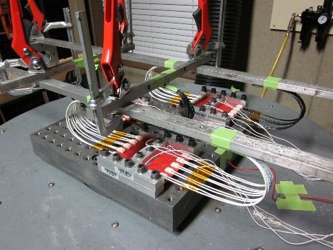

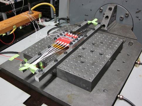
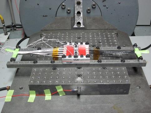
5 Typical Random Vibration Setup Typical Mechanical Shock Setup Figure 4 Rev A 5 of 5
This specification covers performance, tests and quality requirements for MINIPAK* HDL Board Mount Receptacle or Plug Connector System.
 Product Specification 108-2325 25Jun09 Rev B MINIPAK* HDL Board Mount Receptacle or Plug Connector System 1. SCOPE 1.1. Content This specification covers performance, tests and quality requirements for
Mar11 Rev D
 Product Specification 108-1050-1 11Mar11 Rev D MTA-100 Wire-To-Wire Posted Connector System 1. SCOPE 1.1. Content This specification covers the performance, tests and quality requirements for the TE Connectivity
Feb 13 Rev F
 Product Specification IMPACT 100 Ohm Interconnect Systems 108-2351 14 Feb 13 Rev F 1. SCOPE 1.1. Content This specification defines the performance, tests and quality requirements for the TE Connectivity
Mar11 Rev J
 Product Specification 108-1051 11Mar11 Rev J System, Connector/Header, MTA 156 1. SCOPE 1.1. Content This specification covers performance, tests and quality requirements for the TE Connectivity (TE) MTA
NOV 18 Rev B
 Product Specification 14 NOV 18 Rev B Mini-Circular Plastic Connector (CPC) 1. SCOPE 1.1. Content This specification covers performance, tests and quality requirements for the mini-cpc connector system,
Mar07 Rev B
 Product Specification Ultraminiature Coax Connector (UMCC) and Cable Assemblies 108-2231 14Mar07 Rev B 1. SCOPE 1.1. Content This specification covers performance, tests and quality requirements for the
MAY 14 Rev B
 Product Specification 108-2443 29 MAY 14 Rev B Modular, High Density, RF Connection System 1. SCOPE 1.1. Content This specification covers performance, tests and quality requirements for the TE Connectivity
Serial ATA (SATA) Connector
 Connector") Product 108-51052 Specification PRE: Tay Aik Poh 20 MAY 11 Rev G APP: Leong See Fan DCR No. D20110520030314_706049 Serial ATA (SATA) Connector 1.0 SCOPE This specification covers the requirements for product
Product 108-51052 Specification PRE: Tay Aik Poh 20 MAY 11 Rev G APP: Leong See Fan DCR No. D20110520030314_706049 Serial ATA (SATA) Connector 1.0 SCOPE This specification covers the requirements for product
PRODUCT SPECIFICATION. This specification defines the performance, test, quality and reliability requirements of the PwrBlade ULTRA product.
 1 of 10 B 1.0 Objective This specification defines the performance, test, quality and reliability requirements of the PwrBlade ULTRA product. 2.0 Scope This specification is applicable to the termination
Qualification Test Report Mini-Universal MATE-N-LOK* Connector
 Qualification Test Report Mini-Universal MATE-N-LOK* Connector 501-589 21 May 12 Rev B 1. INTRODUCTION 1.1. Purpose 1.2. Scope Testing was performed on the Tyco Electronics Mini-Universal MATE-N-LOK* Connectors
Qualification Test Report SlimSeal SSL Connector
 Qualification Test Report SlimSeal SSL Connector 501-134042 6/26/15 Rev A 1. INTRODUCTION 1.1 Purpose Testing was performed on the TE Connectivity SlimSeal SSL Connector to determine its conformance to
JULY 15 Rev A
 Product Specifcation 108-2467-1 07 JULY 15 Rev A VITA 66.4 Half-Size Fiber Optic Connectors 1. SCOPE 1.1. Content This specification covers the performance, tests and quality requirements for the TE Connectivity
Switch, DIP, Standard 7100 Series
 Product Specification 108-7532 11Mar11 Rev G Switch, DIP, Standard 7100 Series 1. SCOPE 1.1. Content This specification covers performance, tests and quality requirem ents for TE Connectivity (TE) 7100
PRODUCT SPECIFICATION
 0.8x1.2 mm Board to Board Socket Connectors Page 1 1.0 SCOPE This specifies 0.8x1.2mm pitch Socket Connectors. The connector shall meet the performances, specified here under the condition with the plug
PRODUCT SPECIFICATION
 2.54mm Board to Board Socket Connectors Page 1 1.0 SCOPE This specifies 2.54mm pitch Socket Connectors. The connector shall meet the performances, specified here under the condition with the plug connector
PRODUCT SPECIFICATION
 1 of 8 1.0 SCOPE 3 2.0 APPLICABLE DOCUME T...3 3.0 REQUIREME TS.3 4.0 RATI GS 3 5.0 E VIRO ME TAL PERFORMA CE.4 MECHA ICAL PERFORMA CE. 5 6.0 PRODUCT QUALIFICATIO A D REQUALIFICATIO TEST SEQUE CE 8 2 of
PRODUCT SPECIFICATION
 2.54mm Board to Board Header Connectors Page 1 1.0 SCOPE This specifies Pitch 2.54mm Headers Connectors. The connector shall meet the performances, specified here under the condition with the plug connector
3M IDC Ribbon Cable Socket. Series 891
 78-51-- Rev A 1 of 8 M IDC Ribbon Cable Socket Series 891 Product Specification 78-51-- Released: 9-7-11 Austin, TX 7876-9 78-51-- Rev A of 8 Table of Contents Section Page 1. Scope........ M Customer
GS Product Specification. 1 of 19 N. QSFP+ Cable to Board Connector System 1.0 SCOPE 2.0 PRODUCT DESCRIPTION
 1 of 19 N 1.0 SCOPE 2.0 PRODUCT DESCRIPTION 2.1 Product Name and Series Number(s) 2.2 Dimensions, Materials, Plating and Markings 2.3 Additional General Specifications 3.0 REFERENCE DOCUMENTS 3.1 FCI Documents
PRODUCT SPECIFICATION. This specification defines the detailed requirements for the Minitek Pwr3.0 wire to wire and wire to board connectors.
 1.0 SCOPE 1 of 8 E This specification defines the detailed requirements for the Minitek Pwr3.0 wire to wire and wire to board connectors. 2.0 APPLICABLE DOCUMENTS The following documents, of the latest
PRODUCT SPECIFICATION
 Section Table of Contents Page 1.0 Scope 2 2.0 Product Description 2 2.1 Names Series Number(s) 2 Table 1 Wire-To-Wire 2 Table 2 Wire-To-Board 2 2.2 Dimensions, Materials, Platings, Markings 2 2.3 Safety
SOLARLOK PV BAR Junction Box
 SOLARLOK PV BAR Junction Box Table of contents 1. SCOPE... 2 1.1. Content... 2 1.2. Qualification... 3 2. APPLICABLE DOCUMENTS... 3 2.1. TE Connectivity Documents... 3 2.2. Commercial Standard... 3 3.
PRODUCT SPECIFICATION
 MINI-FIT SR. SERIES 1.0 SCOPE This specification covers the 10.00 mm / (.394 in.) centerline tin and gold, silver plated connector series, single and dual row versions in wire to wire and wire to printed
PRODUCT SPECIFICATION
 Section Table of Contents Page 1.0 Scope 2 2.0 Product Description 2 2.1 Names Series Number(s) 2 Table 1 Wire-To-Wire 2 Table 2 Wire-To-Board 2 2.2 Dimensions, Materials, Platings, Markings 2 2.3 Safety
 Distributed by: www.jameco.com 1-800-831-4242 The content and copyrights of the attached material are the property of its owner. EPower Connectors 4.20mm (.165") Pitch Mini-Fit Plus Terminal 46083 Crimp,
 Distributed by: www.jameco.com 1-800-831-4242 The content and copyrights of the attached material are the property of its owner. D 3.00 to 7.92mm (.118 to.312") Pitch FEATURES AND SPECIFICATIONS Features
Product Specification. 3M Cable Assemblies for QSFP+ FDR Applications, Copper
 78-5102-0198-7 A Product Specification 3M Cable Assemblies for QSFP+ FDR Applications, Copper Document Number: 78-5102-0198-7 A Issue Date: Jul 04, 2014 Subject: 3M Cable Assemblies for QSFP+ FDR Applications
SPECIFICATION AND PERFORMANCE CHARACTERISTICS SERIAL ATA CABLE ASSEMBLIES
 SPECIFICATION AND PERFORMANCE CHARACTERISTICS OF SERIAL ATA CABLE ASSEMBLIES CIRCUIT ASSEMBLY CORP. 18 THOMAS STREET, IRVINE, CA 92618-2777 Page No. 1 CONTENTS: 1.0 SCOPE.. 3 2.0 APPLICABLE DOCUMENTS 3
Amphenol Amphenol Taiwan Corporation Sheet 1 of 14
 Amphenol Amphenol Taiwan Corporation Sheet 1 of 14 Title: Part Number: Description: USB3.0 Connector Product Specification GSB34 / GSB35 series Micro Family, Receptacle, SMT, PCB mount Revisions Control
PRODUCT SPECIFICATION
 1.0 SCOPE This Product Specification covers the 1.27 mm (.050 inch) centerline (pitch) printed circuit board (PCB) modular jack connector series with selective gold and tin plating. 2.0 PRODUCT DESCRIPTION
PRODUCT SPECIFICATION
 SMT SHIELDED JACKS W.E. TYPE SYSTEM 1.0 SCOPE This specification covers the Molex shielded W.E. type product line which comprises a shield plug (male) and a jack (female) I/O type connector. This system
PRODUCT SPECIFICATION
 ipass TM 0.8 mm PITCH I/O CONNECTOR REVISION: ECR/ECN INFORMATION: EC No: UCP200-137 DATE: 200 / 02 / 08 TITLE: 1 of 14 TABLE OF CONTENTS 1.0 SCOPE 3 2.0 PRODUCT DESCRIPTION 3 2.1 PRODUCT NAME AND SERIES
PRODUCT SPECIFICATION
 EC No: UC2018-0645 1.0 SCOE This roduct Specification covers the performance requirements and test methods of Micro-Fit 3.00 mm (.118 inch) centerline (pitch) wire to board and wire to wire connector systems
OPEN BASE STATION ARCHITECTURE INITIATIVE
 OPEN BASE STATION ARCHITECTURE INITIATIVE Appendix F Specification for Slim-I/O Panel Mount Cable to Board I/O Connector Version 1.0 Issue 1-0 1 () 9 10 11 1 1 1 1 1 1 1 19 0 1 9 0 1 9 0 1 FOREWORD OBSAI
PRODUCT SPECIFICATION
 i TM / i+ TM 0.8 mm PITCH I/O CONNECTOR SYSTEM of TABLE OF CONTENTS.0 SCOPE... 3.0 PRODUCT DESCRIPTION... 3. PRODUCT NAME AND SERIES NUMBER(S)... 3. DIMENSION, MATERIALS, PLATING AND MARKINGS... 3.3 SAFETY
3M TM High Routability Internal MiniSAS Cable Assembly, Series 8F36
 PRODUCT SPECIFICATION 3M TM High Routability Internal MiniSAS Cable Assembly, Series 8F36 PS-0082 Rev. B Page 1 of 8 3M 2012. All rights Reserved Table of Contents Section Content Page Cover page 1 Contents
SPECIFICATION 宏致電子股份有限公司. No.13, Dongyuan Rd., Jhongli City, Taoyuan County 320, Taiwan (R.O.C.) TEL: FAX:
 TEL: FAX:") SPECIFICATION 宏致電子股份有限公司 Š ã 13 No.13, Dongyuan Rd., Jhongli City, Taoyuan County 320, Taiwan (R.O.C.) TEL: +886-3-463-2808 FAX: +886-3-463-1800 SPEC. NO.: PS-50208-XXXXX-XXX REVISION: E PRODUCT NAME:
SPECIFICATION 宏致電子股份有限公司 Š ã 13 No.13, Dongyuan Rd., Jhongli City, Taoyuan County 320, Taiwan (R.O.C.) TEL: +886-3-463-2808 FAX: +886-3-463-1800 SPEC. NO.: PS-50208-XXXXX-XXX REVISION: E PRODUCT NAME:
3M Wiremount Socket Series CHG
 78-5-- Rev A of M Wiremount Socket Product Specification 78-5-- Released: -- Austin, TX 787-9 78-5-- Rev A Section Table of Contents of Page. Scope........ M Customer Documents......... Performance and
QUALIFICATION TEST SUMMARY REPORT ESR-9414 Qualification Type Testing of Amphenol Corporation s 2M805 Series Connector
 QUALIFICATION TEST SUMMARY REPORT ESR-9414 Qualification Type Testing of Amphenol Corporation s Connector PREPARED BY: Patrick Cole Design Engineer AMPHENOL CORPORATION Aerospace Operation 40-60 Delaware
 Distributed by: www.jameco.com 1-800-831-4242 The content and copyrights of the attached material are the property of its owner. FEATURES AND SPEIFIATIONS Features and Benefits Board-mounting pegs provide
SPECIFICATION 宏致電子股份有限公司 桃園縣中壢市東園路 13 號. No.13, Dongyuan Rd., Jhongli City, Taoyuan County 320, Taiwan (R.O.C.)
") SPECIFICATION 宏致電子股份有限公司 桃園縣中壢市東園路 13 號 No.13, Dongyuan Rd., Jhongli City, Taoyuan County 320, Taiwan (R.O.C.) TEL: +886-3-463-2808 FAX: +886-3-463-1800 SPEC. NO.: PS-50208-XXXXX-XXX REVISION: J PRODUCT
SPECIFICATION 宏致電子股份有限公司 桃園縣中壢市東園路 13 號 No.13, Dongyuan Rd., Jhongli City, Taoyuan County 320, Taiwan (R.O.C.) TEL: +886-3-463-2808 FAX: +886-3-463-1800 SPEC. NO.: PS-50208-XXXXX-XXX REVISION: J PRODUCT
Product Data Sheet. 3M Serial Advanced Technology Attachment (SATA) Boardmount Plug, Receptacle and Cable Assemblies
 Boardmount Plug, Receptacle and Cable Assemblies") PD-0033 Product Data Sheet 3M Serial Advanced Technology Attachment (SATA) Boardmount Plug, Receptacle and Cable Assemblies 3 Electronic Solutions Division Page: 1 of 12 Table of Contents 1.0 Scope...2
PD-0033 Product Data Sheet 3M Serial Advanced Technology Attachment (SATA) Boardmount Plug, Receptacle and Cable Assemblies 3 Electronic Solutions Division Page: 1 of 12 Table of Contents 1.0 Scope...2
 Distributed by: www.jameco.com 1-800-831-4242 The content and copyrights of the attached material are the property of its owner. FEATURES AND SPECIFICATIONS Features and enefits Exceeds Category 5 performance
3M High Routability External MiniSAS Cable Assembly 8G26 Series Product Specification Revised
 Page 1 of 7 Product Specification 78-5102-0099-7 Revised 11-16-11 Contents Title Page and Contents......................................................... 1 1.0 Scope....................................................................
KOAXXA SMA RF Interconnects Innovation & Technology
 Kevin E. Weidner - BSME; RF Interconnect Engineering Manager Daniel Q. Zhu - PhD; Director of Product Development Claude C. de Lorraine - BS Industrial Technology; MBA; Global RF Interconnect Product Manager
USS RF I plug Connector series
 DOC. No.: 651-0089-01 Rev.: D Page: 1/10 1. Application This style products are designed for Mobile phones, Wireless LAN, Mini-PCI, Bluetooth, PDA, GPS, electronic measuring instruments, etc, LAN, Mini-PCI,,PDA,
HAMBURG INDUSTRIES CO., LTD.
 SPECIFICATION OF IC CARD ACCEPTOR Model No.: ICA-607 Revision: 1.0 Issue Date: Oct.15, 2001 HAMBURG INDUSTRIES CO., LTD. 6FL., No.12, Lane 270, Sec. 3, Pei Shen Rd., Shen Keng Hsiang, Taipei Hsien, Taiwan
PRODUCT SPECIFICATION. Single and Multi-Port Jack Assemblies 1 of 26 L
 Single and Multi-Port Jack Assemblies 1 of 26 L Single and Multi-Port Jack Assemblies 2 of 26 L Table of Contents 1. OBJECTIVE... 5 2. SCOPE... 5 3. GENERAL... 5 4. APPLICABLE DOCUMENTS... 5 4.1. Engineering
Powerpole Connectors - PP120: up to 240 Amps
 Powerpole Connectors - : up to 240 Amps series Powerpole housings are designed to accommodate up to 1/0 ( mm²) wires and handle high currents up to 240 amps. Reducing bushings allow to accept down to #8
Qualification Test Report Summary for the Smiths Connectors Solderless EMI Filtered Connector. STR #569 Revision N/C 2/09/09
 for the Smiths Connectors Solderless EMI Filtered Connector Revision N/C 2/09/09 Revision Page Paragraph Description of Revision Approval Letter Number / Appendix Date N/C - - Original Release 2/6/2009
Modular Plug Connectors compliant to Cat.6 A Standard
 Modular Plug Connectors compliant to Cat.6 A Standard TM3P Series Features. Support High-Speed LAN transmission Improved performance by two row contact arrangement. Conforms to Cat.6 A requirements of
Sabritec Qualification Test Report Summary
 Sabritec Qualification Summary Qualification of Multimode Fiber Optic Termini, and Type 1, Category 2 Connectors per ARINC Specification 801 QTR #705 03-27-08 Revision Page Paragraph Description of Revision
FIELD CORRELATED LIFE TEST SUPPLEMENT TO SAE/USCAR-2 SUMMARY OF CONTENTS 1. SCOPE OUTLINE REFERENCED DOCUMENTS EQUIPMENT...
 The Engineering Society For Advancing Mobility Land Sea Air and Space I N T E R N A T I O N A L 400 Commonwealth Drive, Warrendale, PA 15096-0001 SAE/USCAR-20 Issued December 2001 FIELD CORRELATED LIFE
RF, COAXIAL. HYBRID COUPLERS POWER DIVIDERS and DIRECTIONAL COUPLERS GENERIC SPECIFICATION
 1/ 23 Titre / Title RF, COAXIAL HYBRID COUPLERS POWER DIVIDERS and DIRECTIONAL COUPLERS GENERIC SPECIFICATION Written by Responsibility Date Signature P. THIBAUD Space Project manager 29/01/10 Verified
PERFORMANCE SPECIFICATION SHEET SWITCHES, PUSH, 10 AMPERES OR LOW LEVEL, DUSTTIGHT
 INCH-POUND MIL-PRF-8805/3L 23 March 2009 SUPERSEDING MIL-PRF-8805/K 14 March 2003 PERFORMANCE SPECIFICATION SHEET SWITCHES, PUSH, 10 AMPERES OR LOW LEVEL, DUSTTIGHT This specification is approved for use
ASSEMBLY, INSTALLATION, AND REMOVAL OF CONTACTS AND MODULES
 ASSEMBLY, INSTALLATION, AND REMOVAL OF CONTACTS AND MODULES FOR HIGH POWER CONTACTS AND MODULES Table of Contents SECTION 1 RECEIVER CONTACT ASSEMBLY INSTRUCTIONS SECTION 2 ITA CONTACT ASSEMBLY INSTRUCTIONS
Introducing IDC SSL Connector
 Introducing IDC SSL Connector The IDC SSL connector series are insulation displacement (IDC) SMT and thru-hole wire-to-board connectors designed for quick, tool-less termination of discrete wires onto
Application Specification Releasable Poke-in Connector 08JUL 2015 REV:A
 Application Specification 114-137055 Releasable Poke-in Connector 08JUL 2015 REV:A 1. INTRODUCTION This specification covers the requirements for application of Releasable Poke-in connector for use on
MAG-MATE* Series 300 Terminals
 MAG-MATE* Series 300 Terminals Application Specification 114-2046 28 NOV 18 Rev AB All numerical values are in metric units [with U.S. customary units in brackets]. Dimensions are in millimeters [and inches].
PRODUCT SPECIFICATION
 PRODUCT SPCIFICATION MX150L 12-10-8 AWG WIR-TO-WIR, PANL MOUNT PCB HADR CONNCTOR SYSTM 1.0 SCOP This Product specification covers the 7.62 mm (.300 inch) centerline (pitch) Connector Series terminated
EIA STANDARD TP-27B. Mechanical Shock (Specified Pulse) Test Procedure for Electrical Connectors EIA B ELECTRONIC INDUSTRIES ASSOCIATION
 Test Procedure for Electrical Connectors EIA B ELECTRONIC INDUSTRIES ASSOCIATION") ANSI/-1996 Approved: April 17, 1996 EIA STANDARD TP-27B Mechanical Shock (Specified Pulse) Test Procedure for Electrical Connectors (Revision of EIA-364-27A) MAY 1996 ELECTRONIC INDUSTRIES ASSOCIATION
ANSI/-1996 Approved: April 17, 1996 EIA STANDARD TP-27B Mechanical Shock (Specified Pulse) Test Procedure for Electrical Connectors (Revision of EIA-364-27A) MAY 1996 ELECTRONIC INDUSTRIES ASSOCIATION
High Current Pin and Socket Contacts 31 JUL 13 Rev C
 Application Specification High Current Pin and Socket Contacts 31 JUL 13 NOTE NOTE i All numerical values are in metric units [with U.S. customary units in brackets]. Dimensions are in millimeters [and
DETAIL SPECIFICATION SHEET RELAYS, ELECTROMAGNETIC, 10 AMPERES, 2 PDT TYPE I, MAGNETIC LATCH, STUD MOUNTED, SOLDER HOOKS, HERMETICALLY SEALED
 INCH-POUND DETAIL SPECIFICATION SHEET MS25466F 27 November 2003 SUPERSEDING MS25466E 20 Jan 1989 RELAYS, ELECTROMAGNETIC, 10 AMPERES, 2 PDT TYPE I, MAGNETIC LATCH, STUD MOUNTED, SOLDER HOOKS, HERMETICALLY
TEST SUMMARY MINI-FIT JR. CONNECTOR SYSTEM STANDARD AND BLIND MATE INTERFACE (BMI) (WIRE TO PCB AND WIRE TO WIRE)
 (WIRE TO PCB AND WIRE TO WIRE)") SUMMARY MINI-FIT JR. CONNECTOR SYSTEM STANDARD AND BLIND (WIRE TO PCB AND WIRE TO WIRE) 1.0 SCOPE This specification covers the 4.20 mm (.165 inch) centerline connector series terminated with 18 to 24
SUMMARY MINI-FIT JR. CONNECTOR SYSTEM STANDARD AND BLIND (WIRE TO PCB AND WIRE TO WIRE) 1.0 SCOPE This specification covers the 4.20 mm (.165 inch) centerline connector series terminated with 18 to 24
Screw Hole. Figure 1 TOOLING ASSISTANCE CENTER PRODUCT INFORMATION
 Application Specification Solderless Light Emitting Diode (LED) 114-32038 Socket (Type LK) 07 SEP 12 NOTE i All numerical values are in metric units [with U.S. customary units in brackets]. Dimensions
.093 [2.36] Commercial Pin and Socket Connectors
![.093 [2.36] Commercial Pin and Socket Connectors](/thumbs/90/101430850.jpg ".093 [2.36] Commercial Pin and Socket Connectors") .09 [.] Commercial Product Facts Polarized Cavity identification Low contact-mating force Dual locking lances Detent and positive locking Contacts available in brass and phosphor bronze with tin and gold
.09 [.] Commercial Product Facts Polarized Cavity identification Low contact-mating force Dual locking lances Detent and positive locking Contacts available in brass and phosphor bronze with tin and gold
MIL-PRF-83536/5C 08 June 2010 SUPERSEDING MIL-PRF-83536/5B 04 December 2008 PERFORMANCE SPECIFICATION SHEET
 INCH-POUND MIL-PRF-83536/5C 08 June 2010 SUPERSEDING MIL-PRF-83536/5B 04 December 2008 PERFORMANCE SPECIFICATION SHEET RELAYS, ELECTROMAGNETIC, ESTABLISHED RELIABILITY, 4PDT, LOW LEVEL TO 5 AMPERES, PERMANENT
Title:S-ATA DATA Cable Assy
 PRODUT SPEIFIAION Title:S-ATA DATA able Assy S-ATA DATA ABLE ASSY B ADDED ITEM 8 PRODUT SPEIFIATION A NEW RELEASE THIS DOUMENT ONTAINS INFORMATIOON THAT IS PROPRIETARY TO REV. DESRIPTION MOLEX AND SHOULD
SIAMEZE* Standard and Fine Range Terminals
 SIAMEZE* Standard and Fine Range Terminals Application Specification 25 JAN 19 Rev E NOTE All numerical values are in metric units [with U.S. customary units in brackets]. Dimensions are in millimeters
Cluster Block Housings and Contacts
 Cluster Block Housings and Contacts Application Specification 114-2019 20 SEP 17 Rev J NOTE i All numerical values are in metric units [with U.S. customary units in brackets]. Dimensions are in millimeters
EIA STANDARD TP-70B TEMPERATURE RISE VERSUS CURRENT TEST PROCEDURE FOR ELECTRICAL CONNECTORS AND SOCKETS EIA/ECA B. June 2007 EIA/ECA B
 EIA STANDARD ANSI/-2007 Approved: June 8, 2007 TP-70B EIA/ECA-364-70B TEMPERATURE RISE VERSUS CURRENT TEST PROCEDURE FOR ELECTRICAL CONNECTORS AND SOCKETS EIA/ECA-364-70B (Revision of EIA-364-70A) June
Solder Tine Terminal Crimp Wire Terminal. Retention Barb Carrier Strip. Wire Lead-In. Slotted Beams Housing (Customer Supplied) Figure 1
 Figure 1") MAG-MATE* Series 187 Terminals Application Specification 114-2069 28 NOV 18 Rev E All numerical values are in metric units [with U.S. customary units in brackets]. Dimensions are in millimeters [and inches].
MAG-MATE* Series 187 Terminals Application Specification 114-2069 28 NOV 18 Rev E All numerical values are in metric units [with U.S. customary units in brackets]. Dimensions are in millimeters [and inches].
DETAIL SPECIFICATION SHEET
 INCH-POUND MIL-DTL-5530166B 31 May 2012 SUPERSEDING MIL-DTL-5530166B 13 May 2005 DETAIL SPECIFICATION SHEET CONNECTORS, PRINTED CIRCUIT SUBASSEMBLY AND ACCESSORIES: LOW MATING FORCE, MALE BRUSH, STRAIGHT-THROUGH,
PERFORMANCE SPECIFICATION SHEET CONNECTOR, PLUG, ELECTRICAL, TRIAXIAL, RADIO FREQUENCY (SERIES TRB, PIN CONTACT, CLASS 2)
") INCH-POUND MIL-PRF-49142/3G 05 February 2016 SUPERSEDING MIL-PRF-49142/3F 18 April 2005 PERFORMANCE SPECIFICATION SHEET CONNECTOR, PLUG, ELECTRICAL, TRIAXIAL, RADIO FREQUENCY (SERIES TRB, PIN CONTACT,
INCH-POUND MIL-PRF-49142/3G 05 February 2016 SUPERSEDING MIL-PRF-49142/3F 18 April 2005 PERFORMANCE SPECIFICATION SHEET CONNECTOR, PLUG, ELECTRICAL, TRIAXIAL, RADIO FREQUENCY (SERIES TRB, PIN CONTACT,
Test Report. Ochito 10G Ethernet contacts Glenair Part #s: & Qualification Test Report
 Pag. 1of 18 Ochito 10G Ethernet contacts Glenair Part #s: 858-003 & 858-004 Qualification Test Report Conducted by: Approved by: Carlos San Martin Deniz Armani, Ph.D 1. Scope Qualification test report
Powerpole Connectors - PP75: up to 120 Amps
 Powerpole Connectors - PP75: up to 120 Amps PP75 with Mounting Wings PP75 series Powerpole housings can be used for wire-to-wire, wire-to-board, and wire-to-busbar applications. Wire sizes from #16 AWG
Product Data Sheet. 3M Cable Assemblies for SFP+ Applications, Direct Attach Passive Copper
 78-512-114-4 D Product Data Sheet 3M Cable Assemblies for SFP+ Applications, Direct Attach Passive Copper Subject: 3M Cable Assemblies for SFP+ Applications Page: 1 of 14 Table of Contents 1. SCOPE...
DETAIL SPECIFICATION SHEET CONNECTORS, ELECTRICAL, MODULAR, TYPE IV, CONNECTOR, 200 CONTACT, CENTER
 INCH-POUND MIL-DTL-28754/100A 29 December 2015 SUPERSEDING MIL-C-28754/100(SH) 31 October 1989 DETAIL SPECIFICATION SHEET CONNECTORS, ELECTRICAL, MODULAR, TYPE IV, CONNECTOR, 200 CONTACT, CENTER This specification
PERFORMANCE SPECIFICATION SHEET RELAY, ELECTROMAGNETIC PERMANENT MAGNET DRIVE, 25 AMPERES, SPDT, HERMETICALLY SEALED
 INCH-POUND MIL-PRF-6106/19G 18 November 2011 SUPERSEDING MIL-PRF-6106/19F 10 November 2000 PERFORMANCE SPECIFICATION SHEET RELAY, ELECTROMAGNETIC PERMANENT MAGNET DRIVE, 25 AMPERES, SPDT, HERMETICALLY
I-PEX MHF Micro Coaxial Connector Applicable Cable for O.D. 1.37mm Cable
 PRODUCT SPECIFICATION I-PEX MHF Micro Coaxial Connector Applicable Cable for O.D. 1.37mm Cable P/N 20351-112R-37 P/N 20279-001E-01 RF Connector, RF Cable & Antenna Manufacturer E-mail: sales@wellshow.com.tw
Mar11 Rev A
 1. INTRODUCTION 1.1. Purpose 1.2. Scope Engineering Report PARALIGHT* Active Cable Assembly, 4 Lane PN 2123287 502-1304 14Mar11 Rev A Tests were performed on, QSFP 10 Gbs, 4 lane Active Cable assembly
Powerpole Connectors - PP75: up to 120 Amps
 Powerpole Connectors - PP75: up to 120 Amps PP75 with Mounting Wings PP75 series Powerpole housings can be used for wire-to-wire, wire-to-board, and wire-to-busbar applications. Wire sizes from #16 AWG
[ 21.3 ] 0.84 A [ 13.0 ] 0.51
![[ 21.3 ] 0.84 A [ 13.0 ] 0.51](/thumbs/92/108061905.jpg "[ 21.3 ] 0.84 A [ 13.0 ] 0.51") Connectors - up to 175 Amps SBX and SBE connectors can integrate up to 8 auxiliary power / signal contacts along with the two primary power circuits. SBE connectors feature an IEC 60950 touch safe housing
Connectors - up to 175 Amps SBX and SBE connectors can integrate up to 8 auxiliary power / signal contacts along with the two primary power circuits. SBE connectors feature an IEC 60950 touch safe housing
I-PEX MHF3 Micro Coaxial Connector Mating Heigh: 1.5mm MAX
 PRODUCT SPECIFICATION I-PEX MHF3 Micro Coaxial Connector Mating Heigh: 1.5mm MAX P/N 20367-001R P/N 20369-001E RF Connector, RF Cable & Antenna Manufacturer E-mail: sales@wellshow.com.tw Tel: +886-2-24239376
PERFORMANCE SPECIFICATION SHEET
 INCH-POUND 10 August 2016 SUPERSEDING 16 November 2011 PERFORMANCE SPECIFICATION SHEET CONNECTORS, RECEPTACLE, ELECTRICAL, COAXIAL, RADIO FREQUENCY, SERIES SMB (CABLED, PIN CONTACT, JAMNUT MOUNTED, REAR
SBE 320 / SBX 350 Connectors - up to 350 Amps
 Connectors - up to 350 Amps ORDERING INFORMATION SBX and SBE connectors can integrate up to 8 auxiliary power / signal contacts along with the two primary power circuits. Sequencing within auxiliary positions
Application Specification Slim WtoB Poke-in Connector
 Application Specification 114-137049 Slim WtoB Poke-in Connector 18APR 2016 REV:B 1. INTRODUCTION This specification covers the requirements for application of Slim WtoB Poke in connector for use on lighting
Space Level Screening Services
 Space Level Screening Services Phoenix Logistics, Inc., 2507 West Geneva Drive, Tempe, AZ 85282 Tel: 602-231-8616 email: space@phxlogistics.com Web: www.phxlogistics.com Phoenix Logistics, Inc. RF Test
JANUARY 30, 2012 TEST REPORT #211630B MIXED FLOWING GAS TESTING IPS1/IPT1 CONNECTOR SERIES SAMTEC, INC.
 JANUARY 30, 2012 TEST REPORT #211630B MIXED FLOWING GAS TESTING IPS1/IPT1 CONNECTOR SERIES SAMTEC, INC. APPROVED BY: DOMINIC ARPINO PROJECT ENGINEERING MANAGER CONTECH RESEARCH, INC. ATTLEBORO, MA Contech
PERFORMANCE SPECIFICATION SHEET SWITCH, SENSITIVE, LIMIT, HERMETIC SEAL
 INCH-POUND MIL-PRF-8805/80G 29 April 2009 SUPERSEDING MIL-PRF-8805/80F 19 October 200 PERFORMANCE SPECIFICATION SHEET SWITCH, SENSITIVE, LIMIT, HERMETIC SEAL This specification is approved for use by all
ENVIRONMENTAL. Operating Temperature: -40ºC to +125ºC. Wire Gauge Size. Code Accepted Max Wire Gauge Insulation AWG Solid or Stranded
 AVX continues to develop innovative connectors for the industrial electronics market that provide significant benefits over existing, outdated connector solutions. Listening to the design engineering community,
CONNECTORS, ELECTRICAL, CIRCULAR, TRIPLE-START SELF-LOCKING COUPLING, SCOOP-PROOF, REMOVABLE CRIMP CONTACTS BASED ON MIL-C SERIES III
 Page 1 of 24 CONNECTORS, ELECTRICAL, CIRCULAR, TRIPLE-START SELF-LOCKING COUPLING, SCOOP-PROOF, REMOVABLE CRIMP CONTACTS BASED ON MIL-C-38999 SERIES III ESCC Detail Specification Issue 6 October 2013 Document
Modular Plug Connectors Compliant to Enhanced Category 5 Standards
 Modular Plug Connectors Compliant to Enhanced Category 5 Standards TM2P Series (Shielded Type) TM22P-88P (Non-shielded Type) Features. Supports High-Speed LAN Transmission Conforms to requirements of TIA/EIA-568B
303139, Vishay Foil Resistors FEATURES INTRODUCTION. TABLE 1 - TOLERANCE AND TCR VS. RESISTANCE VALUE (- 55 C to C, + 25 C ref.
 Models # 303139 and 303140 - Molded Surface Mount Space and Military Grade Resistors SMRxDZ with Screen/Test Flow in Compliance with EEE-INST-002, (Tables 2A and 3A, Film/Foil, Level 1) and MIL-PRF-55182
Metal Oxide Varistors
 Straight Lead Dimensions Table Series 5D 7D 10D 14D 20D D max 7 9.5 14 17.5 24 d* 0.6 0.6 0.8 0.8 1 W** 5 5 7.5 7.5 10 H max 12.5 14.5 20 22.5 29.5 H1 max 10 12 17 20.5 28 T max 4.9 4.9 8.5 8.5 9 P max
Poke-Home: Inverted Thru Board AWG: WTB INTER CONNECT FEATURES AND BENEFITS APPLICATIONS ELECTRICAL MECHANICAL ENVIRONMENTAL
 AVX continues to develop innovative connectors for the industrial electronics market that provide significant benefits over existing, outdated connector solutions. Listening to the design engineering community,
Oven Controlled Crystal Oscillator OCXO SERIES IEEE 1100
 ELECTRICAL SPECIFICATIONS Min. Typ. Max. Frequency Range* fo 10.000 50.000 MHz Supply Voltage Vs Vs ±5% Power Consumption Warm-up Time Frequency Calibration Frequency Stability vs. Temperature* 3.135 3.3
Attitude Determination and Control Specifications
 Attitude Determination and Control Specifications 1. SCOPE The attitude determination and control sub system will passively control the orientation of the two twin CubeSats. 1.1 General. This specification
SM6T250CAY. Automotive 600 W Transil. Description. Features. Complies with the following standards
 Automotive 600 W Transil Datasheet - production data Complies with the following standards IEC 61000-4-2 exceeds level 4: 30 kv (air discharge) 30 kv (contact discharge) ISO 10605, C = 330 pf, R = 330
DEFENSE LOGISTICS AGENCY DLA Land and Maritime POST OFFICE BOX 3990 COLUMBUS, OH
 DEFENSE LOGISTICS AGENCY DLA Land and Maritime POST OFFICE BOX 3990 COLUMBUS, OH 43218-3990 23 August 2018 MEMORANDUM FOR MILITARY/INDUSTRY DISTRIBUTION SUBJECT: Initial Draft of MIL-PRF-39016/54E. Project