GS Product Specification. 1 of 19 N. QSFP+ Cable to Board Connector System 1.0 SCOPE 2.0 PRODUCT DESCRIPTION
|
|
|
- Alyson Payne
- 5 years ago
- Views:
Transcription
1 1 of 19 N 1.0 SCOPE 2.0 PRODUCT DESCRIPTION 2.1 Product Name and Series Number(s) 2.2 Dimensions, Materials, Plating and Markings 2.3 Additional General Specifications 3.0 REFERENCE DOCUMENTS 3.1 FCI Documents 3.2 Industrial Documents 4.0 QUALIFICATION 5.0 RATINGS 5.1 Voltage 5.2 Current 5.3 Temperature 6.0 PERFORMANCE 6.1 Electrical Characteristics 6.2 ESD Requirements 6.3 EMI Protection 6.4 QSFP+ Pin Assignment Wire Interface EEPROM ( Lower and Upper Page ) 6.6 Mechanical Characteristics 6.7 Environmental Requirements 7.0 QUALITY ASSURANCE PROVISIONS 7.1 Equipment Calibration 7.2 Inspection Conditions 7.3 Sample Quantity and Description 7.4 Acceptance 7.5 Qualification Testing 7.6 Requalification Testing 8.0 SUPPORTING INFORMATION 9.0 REVISION RECORD
2 2 of 19 N 1.0 SCOPE This specification is applicable to the performance characteristics of QSFP+ cable to board connector system. 2.0 PRODUCT DESCRIPTION 2.1 PRODUCT NAME AND SERIES NUMBER(S) Product Series P/N Test Sections Do Not Apply 10G QSFP Cable Assembly G QSFP+ Cable Assembly G QSFP+ Cable Assembly QSFP SMT Board Connector / QSFP Cage / / QSFP Heat Sink QSFP Heat Sink Clip QSFP Cage with Sink and Clip Assembly / Custom QSFP Cable Assembly , 6.4, 6.5 Custom QSFP Cable Assembly , 6.4, G QSFP+ to 4xSFP+ Cable Assembly QSFP End 28G QSFP+ to 4xSFP+ Cable Assembly QSFP End DIMENSIONS, MATERIALS, PLATING AND MARKINGS Refer to the applicable customer drawing for the related dimensional, material, plating, and marking information. 2.3 ADDITIONAL GENERAL SPECIFICATIONS Plug PCB: Material: FR4 Overall thickness: 1.0mm ±0.1(over pads) Mating interface plating: Hard gold over nickel Bulk Cable: As listed on the cable specification drawings.
3 3 of 19 N 3.0 REFERENCE DOCUMENTS 3.1 FCI DOCUMENTS GS GS GS SI SI-VG SI-VG SI-VG GS EL EL Cable Assembly Packaging Specification Board Connector, Cage, and Heat Sink Packaging Specification Board Connector, Cage, and Heat Sink Product Application Specification. 10G QSFP+ Signal Integrity Performance Report (This Applies Only To Standard Part Number) 14G QSFP+ Signal Integrity Performance Report (This only applies to the 14G QSFP+ Part Number) 4x28G QSFP+ Signal Integrity Performance Reports (This applies only to the 28G P/N) 10G Qualification Test Report Summary 14G Qualification Test Report 28G Qualification Test Report 3.2 INDUSTRY DOCUMENTS FIT, FORM AND FUNCTION SFF-8436 QSFP+ Copper and Optical Modules SFF-8661 QSFP+ 28 Gb/s 4X Pluggable Module (Style A) SFF-8662 QSFP+ 28 Gb/s 4X Connector (Style A) or SFF-8672 QSFP+ 28 Gb/s 4X Connector (Style B) SFF-8663 QSFP+ 28 Gb/s 4X Cage (Style A) IEEE Gigabit Ethernet Standard Infiniband IBTA FDR (This applies only to the 14G QSFP+ P/N) InfiniBand IBTA EDR (This applies only to the 4x28G QSFP+ P/N) ITU-T G.957 Synchronous Digital Hierarchy Standard Telcordia Technologies GR-253-CORE JEDEC JESD22-A-114B ESD Specification TEST SPECIFICATON(S) EIA 364 Series Procedure Electrical Connector Test Procedures Including Environmental Classifications with Test
4 4 of 19 N 4.0 QUALIFICATION Connector and cable assemblies furnished under this specification shall be capable of meeting the qualification test requirements specified herein and shall be uniform in quality, and void of all defects that would adversely affect life or serviceability. 5.0 RATINGS 5.1 VOLTAGE 30 Volts AC per Contact (RMS)/DC Max. 5.2 CURRENT 0.5 Amps Max (per contact) 1.0 Amp Max (per power pin) 5.3 TEMPERATURE Operating: -40ºC to +85ºC 6.0 PERFORMANCE 6.1 ELECTRICAL CHARACTERISTICS ITEM DESCRIPTION TEST CONDITION REQUIREMENT LLCR Insulation Resistance Mate connectors: apply a maximum voltage of 320 mv and a current of 10 ma. (EIA 364-6) After 100 VDC for 1 minute, measure the insulation resistance between adjacent mated contacts. (EIA ) 20 milliohm maximum change from initial after environmental exposure 1000 mω Minimum between adjacent contacts Dielectric Withstanding Voltage Apply a voltage of 300 VDC for 1 minute hold between adjacent mated terminals. (EIA , method B) No defect between adjacent contacts Temperature Rise (via Current Cycling) Mate connectors: measure the temperature rise at the rated current after 96 hours (45 minutes ON and 15 minutes OFF per hour). Testing as required. Temperature rise: +30 C MAX.
5 5 of 19 N Differential Impedance Rise time of 70ps (20% to 80%) (EIA ) No significant electrical change Continuity Verify the continuous electrical path of all expected connections No unexpected opens, shorts, or high resistance areas. 6.2 ESD Requirements The module shall meet ESD requirements given in EN , criterion B test specification such that when installed in a properly grounded cage and chassis the units are subjected to 15KV air discharges during operation and 8KV direct contact discharges to the case. The QSFP+ module and host SFI contacts (High Speed Contacts) shall withstand 1000V electrostatic discharge based on human body model per JEDEC JESD22-A114-B. The QSFP+ module and host SFI contacts with the exception of the SFI contacts (High Speed Contacts) shall withstand 2kV electrostatic discharge based on human body model per JEDEC JESD22-A114-B. The QSFP+ module shall meet ESD requirements given in EN , criterion B test specification such that units are subjected to 15kV air discharges during operation and 8kv direct contact discharges to the case. 6.3 EMI Protection The chassis ground of the QSFP+ module is isolated from the modules circuit ground to provide the equipment designer flexibility regarding connections between external electromagnetic interference shields and circuit ground of the module.
6 6 of 19 N 6.4 QSFP+ Cable Assembly Pin Assignment (Figure 3). See Specification SFF section 4. Module mechanicals meet the requirements of specification SFF FIGURE 3 QSFP+ Module Contact Definition
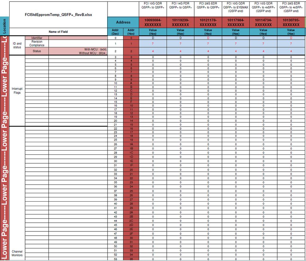
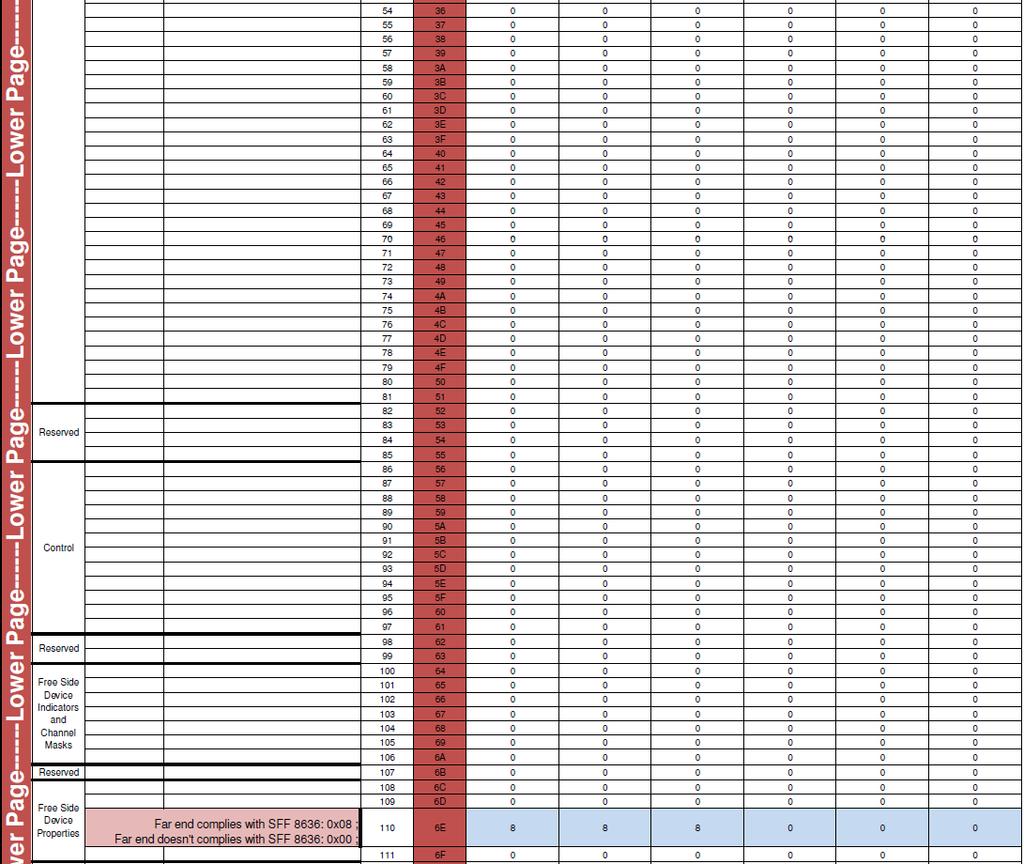
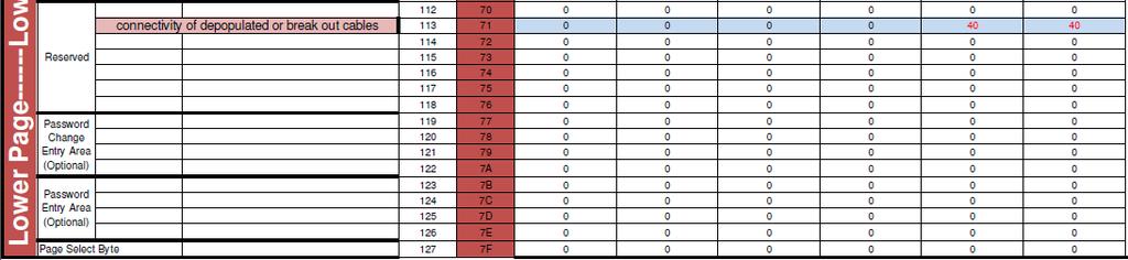
7 7 of 19 N Wire Interface EEPROM The QSFP+ serial ID provides access to sophisticated identification information that describes the Transceiver s capabilities, standard interfaces, manufacturer, and other information. The EEPROM on the QSFP+ passive cable assembly is designed for 255 addresses. 10G QSFP+ & 14G FDR & 28G EDR EEPROM information and source Refer to below document FCI PN FCI STANDARD QSFP FCI STANDARD FDR FCI STANDARD EDR
8 8 of 19 N
9 9 of 19 N


10 10 of 19 N

11 11 of 19 N
12 12 of 19 N MECHANICAL CHARACTERISTICS ITEM DESCRIPTION TEST CONDITION REQUIREMENT Durability Pre-conditioning Mechanical Shock Random Vibration (Insertion & Extraction) Mating & Un-mating Forces Cable Strain Relief Cable Assembly: 50 Cycles Board Connector: 100 cycles Test Condition: 10 cycles per minute max. Latches to be disabled. (EIA , ) Mate and un-mate samples 25 times. Test condition: 10 cycles per minute max. (EIA , ) Mated samples subject to 30G, half-sine shock pulses of 11 milliseconds duration. 3 shocks in each direction applied in 3 mutually perpendicular planes (18 total). EIA , Method H Mate samples subjected to 3.10G rms between 20 and 500 Hz for 15 minutes in each of 3 mutually perpendicular planes EIA , Test Condition: VII Mate and un-mate samples 5 times. Measure the forces with the kick-out springs and latches disengaged. Place axial load on cable. Test Condition: 25mm/min head speed 1. Max. 20mΩ change from initial readings 2. No visual damage No Physical Damage No Physical Damage 1. Max. 20mΩ change from initial readings 2. No visual damage 3. No discontinuances greater than 1µs 1. 40N max mating force 2. 30N max un-mating force 1. 90N Minimum 2. No physical damage. 3. Verify continuity 4. No significant electrical change (Diff Impedance) Wire Flex Cable flex 180º - 15 Cycles Test Condition : See Table 1 and Figure 2 (EIA ) 1. No physical damage. 2. No loss of continuity during test. 3. No significant electrical change (Diff Impedance) Cable Minimum Bend Radius The cable is bent one time over the correct mandrel of size specified in Table 1 in each of 4 perpendicular directions. (Figure 1) 1. No physical damage. 2. Verify continuity 3. No significant electrical change (Diff Impedance) Latch Strength Mate connectors and place an axial load on the cable connector N Minimum 2. No physical damage to the module or cage Cage Press Fit Insertion & Withdrawal Force Place axial load on the cage to measure the insertion and withdrawal force of the press-fit sections into and out of the PCB N Max. Insertion per press-fit section N Min. Extraction per press-fit section.
13 13 of 19 N Raw Cable AWG 8 Pair Standard Minimum Bending Radius Repeated Minimum Bending Radius Single 32AWG ( 51mm ) ( 25.5mm ) 30AWG ( 66mm ) ( 33mm ) 28AWG ( 75mm ) ( 37.5mm ) 26AWG ( 86mm ) ( 43mm ) 24AWG ( 97mm ) ( 48.5mm ) Raw Cable AWG 8 Pair 4x28G Minimum Bending Radius Repeated Minimum Bending Radius Single 30AWG ( 64mm ) ( 32mm ) 26AWG ( 81mm ) ( 41mm ) * Minimum Bend Radius for all non standard cables will use the following formula: Repeated Bending = 10 X Cable Diameter and Single Bending = 5 X Cable Diameter Table 1 Cable Minimum Bend Radius (See Figure 1 & 2) 6.6 ENVIRONMENTAL REQUIREMENTS ITEM DESCRIPTION TEST CONDITION REQUIREMENT Thermal Shock Test Condition: 10 cycles -55ºC to +85ºC. (EIA C, condition I) Max. 20 milliohm change from initial readings Temperature Life Cable should be mated and subject 70ºC for 500 hours EIA , Method A, Condition 2, Time Condition C Max. 20 milliohm change from initial readings Humidity Temperature Cycling Cables unmated specimens to 10 cycles between 25ºC and 65ºC at 80% to 100% relative humidity EIA , Method III excluding steps 7a & 7b Max. 20 milliohm change from initial readings Mixed Flowing Gas Subject the board mounted receptacle to environmental Class IIA for 7 days unmated followed by 7 days mated (14 days total ) EIA , Class IIA Max. 20 milliohm change from initial readings Thermal Disturbance Cables are cycled between 15±3 and 85±3ºC as measured on the part. Ramps at min 2ºC/minute and dwells ensuring contacts reach extremes for 5 minutes minimum. Humidity not controlled. 10 cycles Max. 20 milliohm change from initial readings 7.0 QUALITY ASSURANCE PROVISIONS
14 14 of 19 N 7.1 Equipment Calibration All test equipment and inspection facilities used in the performance of any test shall be maintained in a calibration system in accordance with MIL-C Inspection Conditions Unless otherwise specified herein, all inspections shall be performed under the following ambient conditions: a. Temperature: 25 +/- 5 degrees Celsius b. Barometric Pressure: Local ambient 7.3 Sample Quantity And Description Test Group Number of Cables per wire gage tested Cable Description Each AWG, double ended, 1 meter min Any AWG, single ended, 0.5 meter Any AWG, single ended, 0.5 meter Any AWG, single ended, 0.5 meter Any AWG, single ended, 0.5 meter Any AWG, single ended, 0.5 meter Smallest AWG, single ended, 0.5 meter Largest AWG, single ended, 0.5 meter Non-terminated cables for board side connector durabilty Number of Board Connectors Cages and 3 PCB 3 Board Connectors and 3 Loose Piece connectors Paddle Boards and 1 Cage For qualification test samples, DC blocking capacitors on the receive channels are to be replaced by 0 ohm resistors so that LLCR measurements can be taken on the receive channels.
15 15 of 19 N 7.4 Acceptance Electrical and mechanical requirements placed on test samples as indicated in section 6.0 shall be established from test data using appropriate statistical techniques. All samples tested in accordance with this product specification shall meet the stated requirements Failures attributed to equipment, test set-up, or operator error shall not disqualify the product. If product failure occurs, corrective action shall be taken and samples resubmitted for qualification. 7.5 Qualification Testing Qualification testing shall be performed on sample units produced with equipment and procedures normally used in production. The test sequence shall be as shown in Table Requalification Testing If any of the following conditions occur, the responsible product engineer shall initiate requalification testing consisting of all applicable parts of the qualification test matrix, Table 2. a. A significant design change is made to the existing product, which impacts the product form, fit or function. b. A significant change is made to the manufacturing process, which impacts the product form, fit or function. c. A significant event occurs during production or end use requiring corrective action to be taken relative to the product design or manufacturing process.
16 16 of 19 N TEST TABLE 2 - QUALIFICATION TESTING MATRIX TEST GROUP PARA TEST SEQUENCE Examination of Product 1,12 1,3 1,4 1,11 1,5 1,14 1,11 LLCR ,6,8 2,4 2,5,7,9,11,1 3 2,5,7,9 Insulation Resistance (IR) ,9 Dielectric Withstanding Voltage (DWV) Differential Impedance , ,6,8, 11 Continuity ,5,10 Durability Pre-conditioning Mechanical Shock Random Vibration Mating/Un-mating Force ,12 3,10 Cable Strain Relief Wire Flex Minimum Bend Radii Latch Strength Cage Press-fit Insertion Force Cage Press-fit Withdrawal 3 Thermal Shock Temperature Life Humidity Temperate Cycling Mixed Flowing Gas ,8 Thermal Disturbance
17 17 of 19 N 8.0 SUPPORTING INFORMATION Figure 1 Single Minimum Bending Radius ( See Mechanical Characteristics and Table 1 )
18 18 of 19 N Figure 2 Repeated Wire Flex Test ( See Mechanical Characteristics and Table 1 )
19 19 of 19 N 9.0 REVISION RECORD REV. PAGE DESCRIPTION ECR A All Release from Preliminary V /5/10 B All Rev. A to B, Changed bend radius in Table 1 Repeatable.97 to 2.007, 1.61 to 2.598, 1.69 to 2.952, 1.93 to 3.385, 2.20 to and Single,.69 to 1.004,.81 to 1.299,.85 to 1.476,.96 to 1.693, 1.10 to C 2 Adding new P/N D All Removed E-Prom Address from specification. E 3 F 8 Added applicable information for 14G QSFP+ Cable Assembly Add EEPROM Section back into Spec Updated contents of address 131 to comply with the latest rev of SFF-8436 G 29 Update Test Plan to remove LLCR Step 11 from Test Group 4 H All, 5, 7, 26, 27 Added applicable information for 28G QSFP+ Cable Assembly Updated Impedance requirement, 6.1.5, 6.6.6, 6.6.7, 6.6.8; Added 6.1.6, Updated memory map, Updated the table in section 7.3, Change repeated bend radius Corrected revision change description for Rev H. V /7/10 ECN-ELX-N ECN-ELX-V ECR-ELX-V ECR-ELX-V ECN-ELX-V ECN-ELX-V /2/ /2/ /9/13 J 5, 8, 15, 29, 32 Changed requirement in section 6.1.5, Corrected dec equivalent on address 131, Corrected Vendor OUI, Updated table 2 to add continuity and update sequence of test group 1 ECN-ELX-N K 15 Delete previous EEPROM content and add FCI standard QDR & FDR & EDR EEPROM L 11 Update the QSFP Plus Attenuation table M 2 Adding new P/N N 2,8,10 Revise the map content per the latest industrial spec P 2 Add the QSFP to 4xSFP+ Cable Assembly P/N ECN-ELX-N ECN-ELX-N ECN-ELX-DG ECN-ELX-N ECN-ELX-N /6/
This specification covers performance, tests and quality requirements for MINIPAK* HDL Board Mount Receptacle or Plug Connector System.
 Product Specification 108-2325 25Jun09 Rev B MINIPAK* HDL Board Mount Receptacle or Plug Connector System 1. SCOPE 1.1. Content This specification covers performance, tests and quality requirements for
PRODUCT SPECIFICATION. This specification defines the performance, test, quality and reliability requirements of the PwrBlade ULTRA product.
 1 of 10 B 1.0 Objective This specification defines the performance, test, quality and reliability requirements of the PwrBlade ULTRA product. 2.0 Scope This specification is applicable to the termination
PRODUCT SPECIFICATION
 ipass TM 0.8 mm PITCH I/O CONNECTOR REVISION: ECR/ECN INFORMATION: EC No: UCP200-137 DATE: 200 / 02 / 08 TITLE: 1 of 14 TABLE OF CONTENTS 1.0 SCOPE 3 2.0 PRODUCT DESCRIPTION 3 2.1 PRODUCT NAME AND SERIES
PRODUCT SPECIFICATION
 i TM / i+ TM 0.8 mm PITCH I/O CONNECTOR SYSTEM of TABLE OF CONTENTS.0 SCOPE... 3.0 PRODUCT DESCRIPTION... 3. PRODUCT NAME AND SERIES NUMBER(S)... 3. DIMENSION, MATERIALS, PLATING AND MARKINGS... 3.3 SAFETY
Feb 13 Rev F
 Product Specification IMPACT 100 Ohm Interconnect Systems 108-2351 14 Feb 13 Rev F 1. SCOPE 1.1. Content This specification defines the performance, tests and quality requirements for the TE Connectivity
3M High Routability External MiniSAS Cable Assembly 8G26 Series Product Specification Revised
 Page 1 of 7 Product Specification 78-5102-0099-7 Revised 11-16-11 Contents Title Page and Contents......................................................... 1 1.0 Scope....................................................................
SPECIFICATION AND PERFORMANCE CHARACTERISTICS SERIAL ATA CABLE ASSEMBLIES
 SPECIFICATION AND PERFORMANCE CHARACTERISTICS OF SERIAL ATA CABLE ASSEMBLIES CIRCUIT ASSEMBLY CORP. 18 THOMAS STREET, IRVINE, CA 92618-2777 Page No. 1 CONTENTS: 1.0 SCOPE.. 3 2.0 APPLICABLE DOCUMENTS 3
PRODUCT SPECIFICATION. This specification defines the detailed requirements for the Minitek Pwr3.0 wire to wire and wire to board connectors.
 1.0 SCOPE 1 of 8 E This specification defines the detailed requirements for the Minitek Pwr3.0 wire to wire and wire to board connectors. 2.0 APPLICABLE DOCUMENTS The following documents, of the latest
Mar07 Rev B
 Product Specification Ultraminiature Coax Connector (UMCC) and Cable Assemblies 108-2231 14Mar07 Rev B 1. SCOPE 1.1. Content This specification covers performance, tests and quality requirements for the
Serial ATA (SATA) Connector
 Connector") Product 108-51052 Specification PRE: Tay Aik Poh 20 MAY 11 Rev G APP: Leong See Fan DCR No. D20110520030314_706049 Serial ATA (SATA) Connector 1.0 SCOPE This specification covers the requirements for product
Product 108-51052 Specification PRE: Tay Aik Poh 20 MAY 11 Rev G APP: Leong See Fan DCR No. D20110520030314_706049 Serial ATA (SATA) Connector 1.0 SCOPE This specification covers the requirements for product
PRODUCT SPECIFICATION
 2.54mm Board to Board Socket Connectors Page 1 1.0 SCOPE This specifies 2.54mm pitch Socket Connectors. The connector shall meet the performances, specified here under the condition with the plug connector
PRODUCT SPECIFICATION
 0.8x1.2 mm Board to Board Socket Connectors Page 1 1.0 SCOPE This specifies 0.8x1.2mm pitch Socket Connectors. The connector shall meet the performances, specified here under the condition with the plug
Mar11 Rev J
 Product Specification 108-1051 11Mar11 Rev J System, Connector/Header, MTA 156 1. SCOPE 1.1. Content This specification covers performance, tests and quality requirements for the TE Connectivity (TE) MTA
SEP 15 Rev A
 Product Specification 108-32063 25 SEP 15 Rev A Surface Mount Technology (SMT) Releasable Poke-In Connectors 1. SCOPE 1.1. Content This specification defines performance, tests, and quality requirements
Mar11 Rev D
 Product Specification 108-1050-1 11Mar11 Rev D MTA-100 Wire-To-Wire Posted Connector System 1. SCOPE 1.1. Content This specification covers the performance, tests and quality requirements for the TE Connectivity
PRODUCT SPECIFICATION
 2.54mm Board to Board Header Connectors Page 1 1.0 SCOPE This specifies Pitch 2.54mm Headers Connectors. The connector shall meet the performances, specified here under the condition with the plug connector
MAY 14 Rev B
 Product Specification 108-2443 29 MAY 14 Rev B Modular, High Density, RF Connection System 1. SCOPE 1.1. Content This specification covers performance, tests and quality requirements for the TE Connectivity
NOV 18 Rev B
 Product Specification 14 NOV 18 Rev B Mini-Circular Plastic Connector (CPC) 1. SCOPE 1.1. Content This specification covers performance, tests and quality requirements for the mini-cpc connector system,
Qualification Test Report Mini-Universal MATE-N-LOK* Connector
 Qualification Test Report Mini-Universal MATE-N-LOK* Connector 501-589 21 May 12 Rev B 1. INTRODUCTION 1.1. Purpose 1.2. Scope Testing was performed on the Tyco Electronics Mini-Universal MATE-N-LOK* Connectors
Amphenol Amphenol Taiwan Corporation Sheet 1 of 14
 Amphenol Amphenol Taiwan Corporation Sheet 1 of 14 Title: Part Number: Description: USB3.0 Connector Product Specification GSB34 / GSB35 series Micro Family, Receptacle, SMT, PCB mount Revisions Control
Product Specification. 3M Cable Assemblies for QSFP+ FDR Applications, Copper
 78-5102-0198-7 A Product Specification 3M Cable Assemblies for QSFP+ FDR Applications, Copper Document Number: 78-5102-0198-7 A Issue Date: Jul 04, 2014 Subject: 3M Cable Assemblies for QSFP+ FDR Applications
PRODUCT SPECIFICATION
 Section Table of Contents Page 1.0 Scope 2 2.0 Product Description 2 2.1 Names Series Number(s) 2 Table 1 Wire-To-Wire 2 Table 2 Wire-To-Board 2 2.2 Dimensions, Materials, Platings, Markings 2 2.3 Safety
 Distributed by: www.jameco.com 1-800-831-4242 The content and copyrights of the attached material are the property of its owner. EPower Connectors 4.20mm (.165") Pitch Mini-Fit Plus Terminal 46083 Crimp,
PRODUCT SPECIFICATION
 1.0 SCOPE This Product Specification covers the 1.27 mm (.050 inch) centerline (pitch) printed circuit board (PCB) modular jack connector series with selective gold and tin plating. 2.0 PRODUCT DESCRIPTION
Product Data Sheet. 3M Serial Advanced Technology Attachment (SATA) Boardmount Plug, Receptacle and Cable Assemblies
 Boardmount Plug, Receptacle and Cable Assemblies") PD-0033 Product Data Sheet 3M Serial Advanced Technology Attachment (SATA) Boardmount Plug, Receptacle and Cable Assemblies 3 Electronic Solutions Division Page: 1 of 12 Table of Contents 1.0 Scope...2
PD-0033 Product Data Sheet 3M Serial Advanced Technology Attachment (SATA) Boardmount Plug, Receptacle and Cable Assemblies 3 Electronic Solutions Division Page: 1 of 12 Table of Contents 1.0 Scope...2
Qualification Test Report SlimSeal SSL Connector
 Qualification Test Report SlimSeal SSL Connector 501-134042 6/26/15 Rev A 1. INTRODUCTION 1.1 Purpose Testing was performed on the TE Connectivity SlimSeal SSL Connector to determine its conformance to
Data Center Cabling. QSFP+ Quad Small Form Factor Pluggable Plus 40 Gbps Interconnect System.
 Data Center Cabling QSFP+ Quad Small Form Factor Pluggable Plus 40 Gbps Interconnect System www.lorom.com QSFP+ Quad Small Form Factor Pluggable Plus 40 Gbps Interconnect System Data-transmission speeds
PRODUCT SPECIFICATION
 Section Table of Contents Page 1.0 Scope 2 2.0 Product Description 2 2.1 Names Series Number(s) 2 Table 1 Wire-To-Wire 2 Table 2 Wire-To-Board 2 2.2 Dimensions, Materials, Platings, Markings 2 2.3 Safety
QUALIFICATION TEST SUMMARY REPORT ESR-9414 Qualification Type Testing of Amphenol Corporation s 2M805 Series Connector
 QUALIFICATION TEST SUMMARY REPORT ESR-9414 Qualification Type Testing of Amphenol Corporation s Connector PREPARED BY: Patrick Cole Design Engineer AMPHENOL CORPORATION Aerospace Operation 40-60 Delaware
3M IDC Ribbon Cable Socket. Series 891
 78-51-- Rev A 1 of 8 M IDC Ribbon Cable Socket Series 891 Product Specification 78-51-- Released: 9-7-11 Austin, TX 7876-9 78-51-- Rev A of 8 Table of Contents Section Page 1. Scope........ M Customer
 Distributed by: www.jameco.com 1-800-831-4242 The content and copyrights of the attached material are the property of its owner. FEATURES AND SPECIFICATIONS Features and enefits Exceeds Category 5 performance
PRODUCT SPECIFICATION. Single and Multi-Port Jack Assemblies 1 of 26 L
 Single and Multi-Port Jack Assemblies 1 of 26 L Single and Multi-Port Jack Assemblies 2 of 26 L Table of Contents 1. OBJECTIVE... 5 2. SCOPE... 5 3. GENERAL... 5 4. APPLICABLE DOCUMENTS... 5 4.1. Engineering
 Distributed by: www.jameco.com 1-800-831-4242 The content and copyrights of the attached material are the property of its owner. D 3.00 to 7.92mm (.118 to.312") Pitch FEATURES AND SPECIFICATIONS Features
SPECIFICATION 宏致電子股份有限公司. No.13, Dongyuan Rd., Jhongli City, Taoyuan County 320, Taiwan (R.O.C.) TEL: FAX:
 TEL: FAX:") SPECIFICATION 宏致電子股份有限公司 Š ã 13 No.13, Dongyuan Rd., Jhongli City, Taoyuan County 320, Taiwan (R.O.C.) TEL: +886-3-463-2808 FAX: +886-3-463-1800 SPEC. NO.: PS-50208-XXXXX-XXX REVISION: E PRODUCT NAME:
SPECIFICATION 宏致電子股份有限公司 Š ã 13 No.13, Dongyuan Rd., Jhongli City, Taoyuan County 320, Taiwan (R.O.C.) TEL: +886-3-463-2808 FAX: +886-3-463-1800 SPEC. NO.: PS-50208-XXXXX-XXX REVISION: E PRODUCT NAME:
OPEN BASE STATION ARCHITECTURE INITIATIVE
 OPEN BASE STATION ARCHITECTURE INITIATIVE Appendix F Specification for Slim-I/O Panel Mount Cable to Board I/O Connector Version 1.0 Issue 1-0 1 () 9 10 11 1 1 1 1 1 1 1 19 0 1 9 0 1 9 0 1 FOREWORD OBSAI
compu-shield sfp series
 compu-shield sfp series 20-01 - 2016 INELCO the home of unparalleled quality and service in INterconnection and ELectronic COmponents is a European driven company, manufactoring European ideas, solutions
JULY 15 Rev A
 Product Specifcation 108-2467-1 07 JULY 15 Rev A VITA 66.4 Half-Size Fiber Optic Connectors 1. SCOPE 1.1. Content This specification covers the performance, tests and quality requirements for the TE Connectivity
3M TM High Routability Internal MiniSAS Cable Assembly, Series 8F36
 PRODUCT SPECIFICATION 3M TM High Routability Internal MiniSAS Cable Assembly, Series 8F36 PS-0082 Rev. B Page 1 of 8 3M 2012. All rights Reserved Table of Contents Section Content Page Cover page 1 Contents
PRODUCT SPECIFICATION
 MINI-FIT SR. SERIES 1.0 SCOPE This specification covers the 10.00 mm / (.394 in.) centerline tin and gold, silver plated connector series, single and dual row versions in wire to wire and wire to printed
SPECIFICATION 宏致電子股份有限公司 桃園縣中壢市東園路 13 號. No.13, Dongyuan Rd., Jhongli City, Taoyuan County 320, Taiwan (R.O.C.)
") SPECIFICATION 宏致電子股份有限公司 桃園縣中壢市東園路 13 號 No.13, Dongyuan Rd., Jhongli City, Taoyuan County 320, Taiwan (R.O.C.) TEL: +886-3-463-2808 FAX: +886-3-463-1800 SPEC. NO.: PS-50208-XXXXX-XXX REVISION: J PRODUCT
SPECIFICATION 宏致電子股份有限公司 桃園縣中壢市東園路 13 號 No.13, Dongyuan Rd., Jhongli City, Taoyuan County 320, Taiwan (R.O.C.) TEL: +886-3-463-2808 FAX: +886-3-463-1800 SPEC. NO.: PS-50208-XXXXX-XXX REVISION: J PRODUCT
Qualification Test Report Summary for the Smiths Connectors Solderless EMI Filtered Connector. STR #569 Revision N/C 2/09/09
 for the Smiths Connectors Solderless EMI Filtered Connector Revision N/C 2/09/09 Revision Page Paragraph Description of Revision Approval Letter Number / Appendix Date N/C - - Original Release 2/6/2009
PRODUCT SPECIFICATION
 SMT SHIELDED JACKS W.E. TYPE SYSTEM 1.0 SCOPE This specification covers the Molex shielded W.E. type product line which comprises a shield plug (male) and a jack (female) I/O type connector. This system
PRODUCT SPECIFICATION
 EC No: UC2018-0645 1.0 SCOE This roduct Specification covers the performance requirements and test methods of Micro-Fit 3.00 mm (.118 inch) centerline (pitch) wire to board and wire to wire connector systems
High Speed Interconnects
 High Speed Interconnects The Siemon Interconnect Solutions team has developed a full offering of interconnect assemblies for ultra high-speed point-to-point applications. Supporting speeds up to 40Gb/s
PRODUCT SPECIFICATION
 1 of 8 1.0 SCOPE 3 2.0 APPLICABLE DOCUME T...3 3.0 REQUIREME TS.3 4.0 RATI GS 3 5.0 E VIRO ME TAL PERFORMA CE.4 MECHA ICAL PERFORMA CE. 5 6.0 PRODUCT QUALIFICATIO A D REQUALIFICATIO TEST SEQUE CE 8 2 of
 Distributed by: www.jameco.com 1-800-831-4242 The content and copyrights of the attached material are the property of its owner. FEATURES AND SPEIFIATIONS Features and Benefits Board-mounting pegs provide
Modular Plug Connectors compliant to Cat.6 A Standard
 Modular Plug Connectors compliant to Cat.6 A Standard TM3P Series Features. Support High-Speed LAN transmission Improved performance by two row contact arrangement. Conforms to Cat.6 A requirements of
Switch, DIP, Standard 7100 Series
 Product Specification 108-7532 11Mar11 Rev G Switch, DIP, Standard 7100 Series 1. SCOPE 1.1. Content This specification covers performance, tests and quality requirem ents for TE Connectivity (TE) 7100
Title:S-ATA DATA Cable Assy
 PRODUT SPEIFIAION Title:S-ATA DATA able Assy S-ATA DATA ABLE ASSY B ADDED ITEM 8 PRODUT SPEIFIATION A NEW RELEASE THIS DOUMENT ONTAINS INFORMATIOON THAT IS PROPRIETARY TO REV. DESRIPTION MOLEX AND SHOULD
1.25Gb/s 160km DWDM SFP Transceiver (OP340GD-D ) Hot Pluggable, Duplex LC, 100GHz, DWDM DFB & APD, Single-mode, DDM
 Hot Pluggable, Duplex LC, 100GHz, DWDM DFB & APD, Single-mode, DDM") DWDM 100GHz ITU Grid C Band Available DWDM DFB laser transmitter APD receiver Single +3.3V Power Supply Monitoring Interface Compliant with SFF-8472 Low power dissipation
DWDM 100GHz ITU Grid C Band Available DWDM DFB laser transmitter APD receiver Single +3.3V Power Supply Monitoring Interface Compliant with SFF-8472 Low power dissipation
Mar11 Rev A
 1. INTRODUCTION 1.1. Purpose 1.2. Scope Engineering Report PARALIGHT* Active Cable Assembly, 4 Lane PN 2123287 502-1304 14Mar11 Rev A Tests were performed on, QSFP 10 Gbs, 4 lane Active Cable assembly
HAMBURG INDUSTRIES CO., LTD.
 SPECIFICATION OF IC CARD ACCEPTOR Model No.: ICA-607 Revision: 1.0 Issue Date: Oct.15, 2001 HAMBURG INDUSTRIES CO., LTD. 6FL., No.12, Lane 270, Sec. 3, Pei Shen Rd., Shen Keng Hsiang, Taipei Hsien, Taiwan
I-PEX MHF Micro Coaxial Connector Applicable Cable for O.D. 1.37mm Cable
 PRODUCT SPECIFICATION I-PEX MHF Micro Coaxial Connector Applicable Cable for O.D. 1.37mm Cable P/N 20351-112R-37 P/N 20279-001E-01 RF Connector, RF Cable & Antenna Manufacturer E-mail: sales@wellshow.com.tw
I-PEX MHF3 Micro Coaxial Connector Mating Heigh: 1.5mm MAX
 PRODUCT SPECIFICATION I-PEX MHF3 Micro Coaxial Connector Mating Heigh: 1.5mm MAX P/N 20367-001R P/N 20369-001E RF Connector, RF Cable & Antenna Manufacturer E-mail: sales@wellshow.com.tw Tel: +886-2-24239376
USS RF I plug Connector series
 DOC. No.: 651-0089-01 Rev.: D Page: 1/10 1. Application This style products are designed for Mobile phones, Wireless LAN, Mini-PCI, Bluetooth, PDA, GPS, electronic measuring instruments, etc, LAN, Mini-PCI,,PDA,
Modular Plug Connectors Compliant to Enhanced Category 5 Standards
 Modular Plug Connectors Compliant to Enhanced Category 5 Standards TM2P Series (Shielded Type) TM22P-88P (Non-shielded Type) Features. Supports High-Speed LAN Transmission Conforms to requirements of TIA/EIA-568B
LTF8506 SFP+ AOC 10G Ethernet SFP+ Active Optical Cable
 Product Description he LTF8506 is a SFP+ active optical cable (AOC) for 10Gb Ethernet optical links. It is compliant with the SFF8431 for electrical specification and SFF8432 for mechanical specification.
Product Specification Quadwire FDR Parallel Active Optical Cable FCBN414QB1Cxx
 Product Specification Quadwire FDR Parallel Active Optical Cable FCBN414QB1Cxx PRODUCT FEATURES Four-channel full-duplex active optical cable Eletrical interface only Multirate capability: 1.06Gb/s to
DETAIL SPECIFICATION SHEET
 DETAIL SPECIFICATION SHEET INCH-POUND 21 April 2015 SUPERSEDING 31 May 2005 CONNECTOR, RECEPTACLES, ELECTRICAL, COAXIAL, RADIO FREQUENCY, STRIP OR MICROSTRIP TRANSMISSION LINE, SERIES SMA (SOCKET CONTACT,
Product Specification 10Gb/s Laserwire Serial Data Link Active Cable FCBP110LD1Lxx
 Product Specification 10Gb/s Laserwire Serial Data Link Active Cable FCBP110LD1Lxx PRODUCT FEATURES Single 1.0 10.3125 Gb/s bi-directional link. RoHS-6 compliant (lead-free) Available in lengths of 3,
PRODUCT SPECIFICATION
 PRODUCT SPCIFICATION MX150L 12-10-8 AWG WIR-TO-WIR, PANL MOUNT PCB HADR CONNCTOR SYSTM 1.0 SCOP This Product specification covers the 7.62 mm (.300 inch) centerline (pitch) Connector Series terminated
10G CWDM SFP+ 40km ER Transceiver Hot Pluggable, Duplex LC, +3.3V, 1470~1610nm CWDM EML, DDMI PSFP10-1C41SF-XX
 DATASHEET DESCRIPTION: CWDM SFP+ ER transceiver is a very compact 10Gb/s optical transceiver module for serial optical communication applications, supporting data-rate of 10.3125Gbps (10GBASE-ER) or 9.953Gbps
SOLARLOK PV BAR Junction Box
 SOLARLOK PV BAR Junction Box Table of contents 1. SCOPE... 2 1.1. Content... 2 1.2. Qualification... 3 2. APPLICABLE DOCUMENTS... 3 2.1. TE Connectivity Documents... 3 2.2. Commercial Standard... 3 3.
TEST SUMMARY MINI-FIT JR. CONNECTOR SYSTEM STANDARD AND BLIND MATE INTERFACE (BMI) (WIRE TO PCB AND WIRE TO WIRE)
 (WIRE TO PCB AND WIRE TO WIRE)") SUMMARY MINI-FIT JR. CONNECTOR SYSTEM STANDARD AND BLIND (WIRE TO PCB AND WIRE TO WIRE) 1.0 SCOPE This specification covers the 4.20 mm (.165 inch) centerline connector series terminated with 18 to 24
SUMMARY MINI-FIT JR. CONNECTOR SYSTEM STANDARD AND BLIND (WIRE TO PCB AND WIRE TO WIRE) 1.0 SCOPE This specification covers the 4.20 mm (.165 inch) centerline connector series terminated with 18 to 24
Powerpole Connectors - PP75: up to 120 Amps
 Powerpole Connectors - PP75: up to 120 Amps PP75 with Mounting Wings PP75 series Powerpole housings can be used for wire-to-wire, wire-to-board, and wire-to-busbar applications. Wire sizes from #16 AWG
Ⅲ Optical Characteristics (T OP = -5 to 85, VCC = 3.14 to 3.46 Volts) Parameter Symbol Min Typ Max Unit Ref. Transmitter Output Opt. Pwr POUT -6-1 dbm
 Parameter Symbol Min Typ Max Unit Ref. Transmitter Output Opt. Pwr POUT -6-1 dbm") Ⅰ Absolute Maximum Ratings Parameter Symbol Min Typ Max Unit Ref. Maximum Supply Voltage Vcc -0.5 4.7 V Storage Temperature TS -40 85 C Case Operating Temperature Tcase -5 85 C Ⅱ Electrical Characteristics
Ⅰ Absolute Maximum Ratings Parameter Symbol Min Typ Max Unit Ref. Maximum Supply Voltage Vcc -0.5 4.7 V Storage Temperature TS -40 85 C Case Operating Temperature Tcase -5 85 C Ⅱ Electrical Characteristics
TABLE OF CONTENTS. Sliver Cable Assemblies. TE Connectivity Technical Datasheet
 TABLE OF CONTENTS Introduction... 2 Description... 2 Features and Benefits... 2 Product Applications... 2 Industry Standards... 2 Technical Documents... 2 Part Numbers... 3 Table 1. Part Number Selection
QSFP+ CONNECTORS AND CAGES
 QSFP+ CONNECTORS AND CAGES Quick Reference Guide QSFP+ Solutions Introducing QSFP+ Family QSFP (or quad SFP) connectors provide four channels of data in one pluggable interface. Each channel is capable
Preliminary Product Specification Quadwire 40 Gb/s Parallel Breakout Active Optical Cable FCBN510QE2Cxx APPLICATIONS
 Preliminary Product Specification Quadwire 40 Gb/s Parallel Breakout Active Optical Cable FCBN510QE2Cxx PRODUCT FEATURES Four-channel full-duplex active optical cable with breakout from QSFP+ to four SFP+
JANUARY 30, 2012 TEST REPORT #211630B MIXED FLOWING GAS TESTING IPS1/IPT1 CONNECTOR SERIES SAMTEC, INC.
 JANUARY 30, 2012 TEST REPORT #211630B MIXED FLOWING GAS TESTING IPS1/IPT1 CONNECTOR SERIES SAMTEC, INC. APPROVED BY: DOMINIC ARPINO PROJECT ENGINEERING MANAGER CONTECH RESEARCH, INC. ATTLEBORO, MA Contech
.093 [2.36] Commercial Pin and Socket Connectors
![.093 [2.36] Commercial Pin and Socket Connectors](/thumbs/90/101430850.jpg ".093 [2.36] Commercial Pin and Socket Connectors") .09 [.] Commercial Product Facts Polarized Cavity identification Low contact-mating force Dual locking lances Detent and positive locking Contacts available in brass and phosphor bronze with tin and gold
.09 [.] Commercial Product Facts Polarized Cavity identification Low contact-mating force Dual locking lances Detent and positive locking Contacts available in brass and phosphor bronze with tin and gold
SFP-10G-M 10G Ethernet SFP+ Transceiver
 SFP+, LC Connector, 850nm VCSEL with PIN Receiver, Multi Mode, 300M Features Applications High-speed storage area networks Computer cluster cross-connect Custom high-speed data pipes 10GE Storage, 8G Fiber
3M Wiremount Socket Series CHG
 78-5-- Rev A of M Wiremount Socket Product Specification 78-5-- Released: -- Austin, TX 787-9 78-5-- Rev A Section Table of Contents of Page. Scope........ M Customer Documents......... Performance and
Product Specification Quadwire 40 Gb/s Parallel Active Optical Cable FCCx410QD3Cyy
 Product Specification Quadwire 40 Gb/s Parallel Active Optical Cable FCCx410QD3Cyy PRODUCT FEATURES Four-channel full-duplex active optical cable Multirate capability: 1.06Gb/s to 10.5Gb/s per channel
F i n i s a r. Product Specification Quadwire 40 Gb/s Parallel Active Optical Cable FCBG410QB1Cxx
 Product Specification Quadwire 40 Gb/s Parallel Active Optical Cable FCBG410QB1Cxx PRODUCT FEATURES Four-channel full-duplex active optical cable Electrical interface only Multirate capability: 1.06Gb/s
Powerpole Connectors - PP75: up to 120 Amps
 Powerpole Connectors - PP75: up to 120 Amps PP75 with Mounting Wings PP75 series Powerpole housings can be used for wire-to-wire, wire-to-board, and wire-to-busbar applications. Wire sizes from #16 AWG
10Gb/s SFP+ Optical Transceiver Module 10GBASE-SR/SW
 10Gb/s SFP+ Optical Transceiver Module 10GBASE-SR/SW Features 10Gb/s serial optical interface compliant to 802.3ae 10GBASE SR Electrical interface compliant to SFF 8431 specifications for enhanced 8.5
Powerpole Connectors - PP75: up to 120 Amps
 Powerpole Connectors - PP75: up to 120 Amps PP75 with Mounting Wings PP75 series Powerpole housings can be used for wire-to-wire, wire-to-board, and wire-to-busbar applications. Wire sizes from #16 AWG
PORTE-CLIPS 12 VOIES MQS GENE II MQS MARK II 12-POSITION RECEPTACLE HOUSING. Traduit par le Service Technique le 16 septembre 2002
 PORTE-CLIPS 12 VOIES MQS GENE II MQS MARK II 12-POSITION RECEPTACLE HOUSING Product Specification 19 NOV 2001 Rev. 0 Traduit par le Service Technique le 16 septembre 2002 1. SCOPE This specification defines
TPP3XGDS0x000E2G 850nm SFP+ Transceiver
 Features 850nm VCSEL laser TPP3XGDS0x000E2G Transmission distance up to 300m on OM3 MM fiber Low power consumption Wide Case Operating Temperature Range Compliant with SFP+ Electrical MSA SFF-843 Compliant
10G SFP+ CWDM 20km Transceiver Hot Pluggable, Duplex LC, +3.3V, 1270~1350nm CWDM DFB, DDMI PSFP-2C41SF-XX
 DATASHEET DESCRIPTION: transceiver is a very compact 10Gb/s optical transceiver module for serial optical communication applications, supporting data-rate of 10.3125Gbps (10GBASE-LR) or 9.953Gbps (10GBASE-LW),
Pluggable Input / Output Solutions
 SFP+ Products Product Facts SFP+ interconnect system supports data rates of 10 Gb/s Connector designed to support 10 Gb/s+ signal speeds, backward compatible with SFP Both EMI spring and gasket options
10Gb/s SFP+ BX LC DDMI Optical module Tx:1330nm/Rx:1270nm 10km transmission distance
 Feature 10Gb/s serial optical interface compliant to 802.3ae 10GBASE-LR, single LC connector for bi-directional application, over 10km SMF Electrical interface compliant to SFF-8431 specifications for
CFORTH-QSFP/4SFP+-AOCxM Specifications Rev. D00A. Product Features
 Preliminary DATA SHEET CFORTH-QSFP/4SFP+-AOCxM 40Gb/s QSFP+ to 4xSFP+ Active Optical Cable Transceiver CFORTH-QSFP/4SFP+-AOCxM Overview CFORTH-QSFP/4SFP+-AOCxM QSFP+ to 4xSFP+ active optical cable transceivers
SURFACE MOUNT HIGH REPEATABILITY SPDT, BROADBAND 18 GHZ 40GBPS MAGNETIC-LATCHING RF RELAY
 SURFACE MOUNT HIGH REPEATABILITY SPDT, BROADBAND 18 GHZ 40GBPS MAGNETIC-LATCHING RF RELAY Series GRF121/GRF121R SERIES GRF121 GRF121R RELAY TYPE RF Magnetic-Latching, SPDT, Common Coil Negative, Surface
R10-FA-01 Ruggedized Edge Filter for Xenus: User Guide
 R10-FA-01 Ruggedized Edge Filter for Xenus: User Guide P/N 95-01178-000 Revision 1 January 2009 R10-FA-01 Ruggedized Edge Filter for Xenus This page for notes. TABLE OF CONTENTS About This Guide... 5 Overview
SECTION 5 SWITCHING CONNECTORS/MOEBIUS MC-CARD/RP-MCX R199/R299 SIMPLIFICATION IS OUR INNOVATON. Visit for more information
 SECTION 5 SWITCHING CONNECTORS/MOEBIUS MC-CARD/RP-MCX R199/R299 SIMPLIFICATION IS OUR INNOVATON Visit www.radiall.com for more information Contents Introduction... 5-4 to 5-5 MOEBIUS Characteristics...
Powerpole Connectors - PP120: up to 240 Amps
 Powerpole Connectors - : up to 240 Amps series Powerpole housings are designed to accommodate up to 1/0 ( mm²) wires and handle high currents up to 240 amps. Reducing bushings allow to accept down to #8
SURFACE MOUNT HIGH REPEATABILITY SPDT, BROADBAND 16 GHZ 40GBPS MAGNETIC-LATCHING RF RELAY
 SURFACE MOUNT HIGH REPEATABILITY SPDT, BROADBAND 16 GHZ 40GBPS MAGNETIC-LATCHING RF RELAY Series GRF121 SERIES GRF121 RELAY TYPE RF Magnetic-Latching, SPDT, Surface Mount Relay DESCRIPTION The ultraminiature
KOAXXA SMA RF Interconnects Innovation & Technology
 Kevin E. Weidner - BSME; RF Interconnect Engineering Manager Daniel Q. Zhu - PhD; Director of Product Development Claude C. de Lorraine - BS Industrial Technology; MBA; Global RF Interconnect Product Manager
JDX Hybrid Mixed Power & Signal
 Integrated Mixed Power Backshell and Signal Fire Waterproof Connector The JDX mixed power and signal connector offers the ability to integrate 2 or 3 power contacts with 6 to 8 signal contacts in one connector
LoopBack Relay. GLB363 Series. With Built-in AC Bypass Capacitors / DC LoopBack Relay
 GLB363 Series With Built-in AC Bypass Capacitors / DC SERIES DESIGNATION GLB363 RELAY TYPE, Sensitive Coil, Surface Mount Ground Shield and Stub pins with AC Bypass Capacitors or No capacitor DESCRIPTION
QUADSPLITTER AND IN-LINE QUADSPLITTER
 QUADSPLITTER AND IN-LINE QUADSPLITTER technical characteristics specifications temperature rating: -55 c to + 5 c corrosion: MIL-STD-0 Method 0, Test Condition B shock: MIL-STD-0 Method, Test Condition
DETAIL SPECIFICATION SHEET
 INCH-POUND MIL-DTL-5530166B 31 May 2012 SUPERSEDING MIL-DTL-5530166B 13 May 2005 DETAIL SPECIFICATION SHEET CONNECTORS, PRINTED CIRCUIT SUBASSEMBLY AND ACCESSORIES: LOW MATING FORCE, MALE BRUSH, STRAIGHT-THROUGH,
SPL EBX-IDFM SPL EBX-IDFM
 Features 155Mbps data links Up to 20km point-point transmission on SMF 1310nm FP transmitter and 1550nm PIN receiver for 1550nm FP transmitter and 1310nm PIN receiver for SFP MSA package with LC connector
SFP+ 10G Transceiver M10GB-SFP-BIDI10
 SFP+ 10G Transceiver M10GB-SFP-BIDI10 Features: Supports 9.95Gb/s to 10.5Gb/s bit rates Hot-pluggable SFP+ footprint Single LC for Bi-directional Transmission Maximum link length of 10km Built-in 1270/1330
Modular Plug Connectors Compliant to Enhanced Category 5 Standards
 Modular Plug Connectors Compliant to Enhanced Category 5 Standards TM2P Series (Shielded Type) TM22P-88P (Non-shielded Type) Features. Supports High-Speed LAN Transmission Conforms to requirements of TIA/EIA-568B
PERFORMANCE SPECIFICATION SHEET
 INCH-POUND 10 August 2016 SUPERSEDING 16 November 2011 PERFORMANCE SPECIFICATION SHEET CONNECTORS, RECEPTACLE, ELECTRICAL, COAXIAL, RADIO FREQUENCY, SERIES SMB (CABLED, PIN CONTACT, JAMNUT MOUNTED, REAR
ASSEMBLY, INSTALLATION, AND REMOVAL OF CONTACTS AND MODULES
 ASSEMBLY, INSTALLATION, AND REMOVAL OF CONTACTS AND MODULES FOR HIGH POWER CONTACTS AND MODULES Table of Contents SECTION 1 RECEIVER CONTACT ASSEMBLY INSTRUCTIONS SECTION 2 ITA CONTACT ASSEMBLY INSTRUCTIONS
Application Note 5044
 HBCU-5710R 1000BASE-T Small Form Pluggable Low Voltage (3.3V) Electrical Transceiver over Category 5 Unshielded Twisted Pair Cable Characterization Report Application Note 5044 Summary The Physical Medium