Mechanical Engineering Drawing
|
|
|
- Joy Baldwin
- 6 years ago
- Views:
Transcription
1 Mechanical Engineering Drawing MECH 211 LECTURE 3
2 Contents of the lecture Shape description Shape generation Sectional views Auxiliary views
3 Shape description Geometric shapes are seen according to view they are regarded Set of primitives used to conceptualize the complex shapes by adding/subtracting the primitive shapes Primitive shapes: Boxes Prisms Pyramids/truncated pyramids Cylinders Cones Spheres

4 Primitives
5 Primitives shape generation
6 Boolean operations Given two shapes, they could be intersected or reunited to obtain a new shape

7 Boolean union The common part is removed once


8 Boolean difference The initial shape minus the common portion will be yielded notice the difference A-B versus B-A

9 Boolean intersection The intersection means the common portion of the two intersecting bodies


10 Another example

11 Conceptual generation of a complex shape

12 Conceptual generation of a complex shape
13 Shape generation Two different aspects of shape generation: Conceptual shape generation when the geometry does not exist and when a functional do-able shape is created Physical shape generation when the geometric object is physically created/generated by machining Physical generation involves material selection, machine tool and tools selections


14 Conceptual shape generation The concept is created by the human judgment The concept can be translated in codes create models
15 Physical shape generation Planes: flat surfaces Polyhedrons: inclined flat surfaces Cylindrical/conical surfaces: round surfaces, holes Ruled surfaces/non-ruled surfaces: complex kinematics cutting or forming in complex shape dies
16 Physical shape generation Two basic principle methods are used to generate surfaces: Forming create shape form a shapeable material: ex» Casting» Deformation (forging, bending, squeezing, etc.)» Growing (nature s way ex: stereo-lithography) Cutting create shape through removal out of a larger piece of material» Turning, milling, drilling, grinding, lapping, etc. Multiple types of operations are used to generate the same class of shapes various surface qualities are obtained for various materials
17 Shape generation of primitives Boxes flat surface Cylinders round surfaces Prisms flat surface Cones round surfaces Spherical double curved As a general principle, the cutting tool and work piece move one with respect to the other; the cutting tool will remove the undesired volume of material from the work
18 Machining procedures Shaping and planing Turning Milling Drilling Sawing Broaching Grinding FORMING PROCESS Hot working Cold working CASTING PROCESS JOINING PROCESS NON-CONVENTIONAL PROCESSES
19 Generation of Flat surfaces Shaping and planing

20 Turning
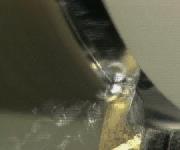
21 Turning
22 Milling
23 Milling
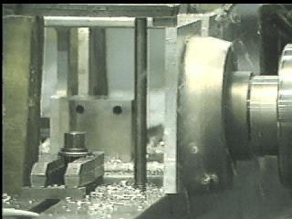
24 Milling

25 Drilling

26 Sawing
27 Sawing

28 Broaching

29 Grinding
30 SECTION VIEWS
31 Purpose of sectioning Provide the details of the features that are invisible in a normal view A cutting plane is assumed to pass through the conveniently selected features If the plane passes through the object, the view is called a FULL SECTION Cutting plane is indicated on the adjacent view
32


33 SECTIONAL VIEW Why do we use sectional views?
34 SECTIONAL VIEW TYPES Full Sections Half Sections Offset Sections Broken Sections Revolved Sections Conventional Breaks Partial Views
35 ELEMENTS IN SECTIONAL VIEWS Cutting Plane An assumed plane passes through the part to expose the interior construction. Different cutting planes make different types of sectional views
36 A B A B Section AA Section BB
37 A B A B Section AA Section BB

38 The cutting plane
39 Is the section view really needed?
40 ELEMENTS IN SECTIONAL VIEWS Cutting-Plane Line Location Line Type Arrowheads Capital Letters

41 Indicate the cutting plane
42 Basic representation rules

43 Section lines (lining)

44 Section lines

45 Common mistakes

46 Common mistakes

47 Difficult cases
48 HALF SECTIONS If a cutting plane passes halfway through an object, the result is a half section. Expose the interior and retain the exterior. It is often used for symmetrical objects, not for detail drawings.
49 Half sections Convenient way to show the view and section in symmetric parts
50 BROKEN-OUT SECTIONS If only a partial section of a view is needed to expose interior shapes, a break line is used for the section. The section is limited.
51 Broken out sections

52 REVOLVED SECTIONS To show the shape of cross section of bars, arms, spokes, a plane perpendicular to the center line of the part cuts through. Then rotate the plane by 90 around a line at right angle to the center line.

53 Revolved sections Assume a section plane perpendicular to the front axis of the component; revolve the plane to see the section as a true shape
54 Removed section
55 Aligned sections
56 Aligned sections
57 Offset section Necessary when features to show are located in different planes

58 Sections through assemblies
59 Pay attention to lining

60 Pay attention to representation
61 Pay attention to representation
62 Pay attention to representation

63 Section in a flange
64 AUXILIARY VIEWS
65 Definitions Any view obtained by a projection on a plane other than the horizontal (H), frontal (F) and profile (P) is an auxiliary view. Primary auxiliary is projected to a plane that is perpendicular to one of the principal planes Secondary auxiliary is projected from a primary auxiliary to a plane that is inclined to all three principal views

66 Auxiliary view
67 Candidates for auxiliary views

68 Principal planes

69 Auxiliary plane

70 Primary auxiliary view Plane True Dim. F Width, Height H Width, Depth P Depth, Height

71 Primary auxiliary view
72 DEPTH AUXILIARY VIEWS A projection plane is perpendicular to the frontal view, and oblique to the top (or side ) view. The auxiliary view is based on the frontal view. Depth in Auxiliary View = Depth in Top (Side) View
73 HEIGHT AUXILIARY VIEWS A projection plane is perpendicular to the top view, and oblique to the frontal (side) view. The auxiliary view is based on the top view. Height in Auxiliary View = Height in Frontal (Side) View
74 WIDTH AUXILIARY VIEWS A projection plane is perpendicular to the side view, and oblique to the frontal (or top) view. The auxiliary view is based on the side view. Width in Auxiliary View = Width in Frontal (Top) View
75 The features in auxiliary planes are seen deformed in the principal views
76 The features in auxiliary planes are seen deformed in the principal views

77 The features in auxiliary planes are seen deformed in the principal views
78 How to represent a full auxiliary view? Folding-Line Method
79 How to represent a full auxiliary view?
80 How to represent a full auxiliary view?
81 How to represent a full auxiliary view?
82 DIHEDRAL ANGLES Definition: An angle between two intersection planes Figure (a) shows a dihedral angle between surface A and B. To find the angle for the case in Figure (b), auxiliary view is used.
83 A practical problem Find the angle of the V-cut
84 SOLUTION: TURE SIZE OF AN OBLIQUE SURFACE 1. Find the edge view of the plane in a primary auxiliary view 2. Find the true size of the plane in a secondary auxiliary view
85 Another practical problem Find the true shape of the section (triangle)
86 1. Select fold line 2. Draw perp. To F/L 3. Transfer the dist. From the previous F/L 4. Check the visibility
87 1. Select fold line 2. Draw perp. To F/L 3. Transfer the dist. From the previous F/L 4. Check the visibility
88 1. Select fold line 2. Draw perp. To F/L 3. Transfer the dist. From the previous F/L 4. Check the visibility
89 1. Select fold line 2. Draw perp. To F/L 3. Transfer the dist. From the previous F/L 4. Check the visibility
90 1. Select fold line 2. Draw perp. To F/L 3. Transfer the dist. From the previous F/L 4. Check the visibility
91 DIHEDRAL ANGLES Definition: An angle between two intersection planes Figure (a) shows a dihedral angle between surface A and B. To find the angle for the case in Figure (b), auxiliary view is used.
92 A practical problem Find the angle of the V-cut
93 SOLUTION: TURE SIZE OF AN OBLIQUE SURFACE 1. Find the edge view of the plane in a primary auxiliary view 2. Find the true size of the plane in a secondary auxiliary view

94 Another practical problem Find the true shape of the section (triangle)

95 Example of auxiliary view problem Find the true shape of the distorted features

96 Example of auxiliary view problem One feature is seen in P view as a line one auxiliary view needed

97 Example of auxiliary view problem Another feature is seen in F view as a line one auxiliary view needed
98 Auxiliary Views: To draw TL of line, point view of line, Edge view of the plane and true size of plane. To View TL : Draw Aux.View parallel to any view To view point view: Draw Aux.View perp. To TL To view Edge View : Draw Aux.View perp. To TL of any edge/line To view full surface : Draw Aux.View perp. Edge view
Multiviews and Auxiliary Views
 Multiviews and Auxiliary Views Multiviews and Auxiliary Views Objectives Explain orthographic and multiview projection. Identifying the six principal views. Apply standard line practices to multiviews
Engineering Graphics, Class 13 Descriptive Geometry. Mohammad I. Kilani. Mechanical Engineering Department University of Jordan
 Engineering Graphics, Class 13 Descriptive Geometry Mohammad I. Kilani Mechanical Engineering Department University of Jordan Projecting a line into other views Given the front and right side projections
AUXILIARY VIEWS C H A P T E R N I N E
 AUXILIARY VIEWS C H A P T E R N I N E Giesecke, Hill, Spencer, Dygdon, Novak, Lockhart, Goodman 1 OBJECTIVES 1. Create an auxiliary view from orthographic views. 2. Draw folding lines or reference-plane
Mechanical Drawing. Unit 2 Study Guide for Chapters 6-10
 Mechanical Drawing Unit 2 Study Guide for Chapters 6-10 Chapter 6 Multiview Drawing Section 6.1 Understanding Orthographic Projection A. Technical Drawing: How can a technical drawing give more accurate
Engineering Graphics, Class 8 Orthographic Projection. Mohammad I. Kilani. Mechanical Engineering Department University of Jordan
 Engineering Graphics, Class 8 Orthographic Projection Mohammad I. Kilani Mechanical Engineering Department University of Jordan Multi view drawings Multi view drawings provide accurate shape descriptions
Auxiliary view KCEC1101
 Auxiliary view KCEC1101 Introduction There are times when one of the six principal views will not completely describe an object. This is especially true when there are inclined or oblique planes or features
ME1105 Engineering Drawing & Design
 City University London Term 1 Assessment 2008/2009 School of Engineering and Mathematical Sciences ME1105 Engineering Drawing & Design Student Name:.., Group: Examination duration: Reading time: This paper
ORTHOGRAPHIC PROJECTION
 ORTHOGRAPHIC PROJECTION C H A P T E R S I X OBJECTIVES 1. Recognize and the symbol for third-angle projection. 2. List the six principal views of projection. 3. Understand which views show depth in a drawing
UNIT 5a STANDARD ORTHOGRAPHIC VIEW DRAWINGS
 UNIT 5a STANDARD ORTHOGRAPHIC VIEW DRAWINGS 5.1 Introduction Orthographic views are 2D images of a 3D object obtained by viewing it from different orthogonal directions. Six principal views are possible
2009 Academic Challenge
 2009 Academic Challenge ENGINEERING GRAPHICS TEST SECTIONAL This Test Consists of 50 Questions Engineering Graphics Test Production Team Ryan Brown, Illinois State University Author/Team Leader Kevin Devine,
Multi-View Drawing Review
 Multi-View Drawing Review Sacramento City College EDT 300/ENGR 306 EDT 300 / ENGR 306 - Chapter 5 1 Objectives Identify and select the various views of an object. Determine the number of views needed to
ENGINEERING DRAWING. UNIT III - Part A
 DEVELOPMENT OF SURFACES: ENGINEERING DRAWING UNIT III - Part A 1. What is meant by development of surfaces? 2. Development of surfaces of an object is also known as flat pattern of the object. (True/ False)
Copyrighted Material. Copyrighted Material. Copyrighted. Copyrighted. Material
 Engineering Graphics ORTHOGRAPHIC PROJECTION People who work with drawings develop the ability to look at lines on paper or on a computer screen and "see" the shapes of the objects the lines represent.
2007 Academic Challenge
 2007 Academic Challenge ENGINEERING GRAPHICS TEST - STATE FINALS This Test Consists of 50 Questions Engineering Graphics Test Production Team Ryan Brown, Illinois State University Author/Team Coordinator
A Concise Introduction to Engineering Graphics
 A Concise Introduction to Engineering Graphics Fourth Edition Including Worksheet Series A Timothy J. Sexton, Professor Department of Industrial Technology Ohio University BONUS Book on CD: TECHNICAL GRAPHICS
Dr Ghassan Al-Kindi - MECH2118 Lecture 9
 Dr Ghassan Al-Kindi - MECH2118 Lecture 9 Machining A material removal process in which a sharp cutting tool is used to mechanically cut away material so that the desired part geometry remains Most common
Descriptive Geometry CH17 : DEVELOPMENTS
 Descriptive Geometry CH17 : DEVELOPMENTS Developments A development is a flat representation or pattern that when folded together creates a 3D object. Developable Surfaces A developable surface may be
ENGINEERING DRAWING. 1. Set squares are used to draw different angles. What is the angel a formed by the 45⁰ set square? Give a brief answer.
 ENGINEERING DRAWING 1. Set squares are used to draw different angles. What is the angel a formed by the 45⁰ set square? Give a brief answer. 2. Which is the correct method of hatching a plane surface?
ORTHOGRAPHIC PROJECTIONS. Ms. Sicola
 ORTHOGRAPHIC PROJECTIONS Ms. Sicola Objectives List the six principal views of projection Sketch the top, front and right-side views of an object with normal, inclined, and oblique surfaces Objectives
DMT113 Engineering Drawing. Chapter 3 Stretch System
 DMT113 Engineering Drawing Chapter 3 Stretch System Contents Theory & Multiview Planes 6 Principle Views Multiview Sketching Technique & Perspective First & Third Angle Multiview Representations Theory
Figure 8-1 Regular Views and Auxiliary Views. 2003, Prentice-Hall, Inc. Giesecke Technical Drawing, 12e
 Figure 8-1 Regular Views and Auxiliary Views. Figure 8-2 An Auxiliary View. Figure 8-3 Drawing an Auxiliary View Folding-Line Method. Figure 8-4 Drawing Parallel or Perpendicular Lines. Figure 8-5 Position
A Concise Introduction to Engineering Graphics
 Concise Introduction to Engineering Graphics ourth Edition Including Worksheet Series imothy J. Sexton, Professor Department of Industrial echnology Ohio University ONUS ook on CD: ECHNICL GRPHICS Meyers,
Chapter 5 SECTIONS OF SOLIDS 5.1 INTRODUCTION
 Chapter 5 SECTIONS OF SOLIDS 5.1 INTRODUCTION We have studied about the orthographic projections in which a 3 dimensional object is detailed in 2-dimension. These objects are simple. In engineering most
GL5: Visualisation and reading drawings
 436-105 Engineering Communications GL5:1 GL5: Visualisation and reading drawings Being able to both: represent a 3D object in multiview drawings interpret a multiview drawing to visualise a 3D object is
SDC PUBLICATIONS. Schroff Development Corporation
 SDC PUBLICATIONS Schroff Development Corporation www.schroff.com www.schroff-europe.com SECTIONING In chapter 3 you will learn how to create various types of sectional views. Sectional views allow you
CLASS views from detail on a grid paper. (use appropriate line types to show features) - Optional views. Turn in for grading on class 6 (06/04)
 - Optional views. Turn in for grading on class 6 (06/04)") CLASS 4 Review: - Projections - Orthographic projections Lab: - 3 views from detail on a grid paper. (use appropriate line types to show features) - Optional views. Turn in for grading on class 6 (06/04)
CLASS 4 Review: - Projections - Orthographic projections Lab: - 3 views from detail on a grid paper. (use appropriate line types to show features) - Optional views. Turn in for grading on class 6 (06/04)
Multiview Drawing. Definition: Graphical representation of a 3- dimensional object on one plane (sheet of paper) using two or more views.
 using two or more views.") Multiview Drawing Definition: Graphical representation of a 3- dimensional object on one plane (sheet of paper) using two or more views. Multiview Drawing Another name for multiview drawing is orthographic
Multiview Drawing Definition: Graphical representation of a 3- dimensional object on one plane (sheet of paper) using two or more views. Multiview Drawing Another name for multiview drawing is orthographic
ME 113 Computer Aided Engineering Drawing
 ME 113 Computer Aided Engineering Drawing Orthographic Projection - Visualizing Solids and Multiview Drawings Asst.Prof.Dr.Turgut AKYÜREK Çankaya University, Ankara Visualizing Solids and Multiview Drawings
Appendix. Springer International Publishing Switzerland 2016 A.Y. Brailov, Engineering Graphics, DOI /
 Appendix See Figs. A.1, A.2, A.3, A.4, A.5, A.6, A.7, A.8, A.9, A.10, A.11, A.12, A.13, A.14, A.15, A.16, A.17, A.18, A.19, A.20, A.21, A.22, A.23, A.24, A.25, A.26, A.27, A.28, A.29, A.30, A.31, A.32,
MULTIPLE CHOICE QUESTIONS - CHAPTER 6
 MULTIPLE CHOICE QUESTIONS - CHAPTER 6 1. The selection of the front view in executing a multiview drawing of an object is dependent upon the following factors: a. size and shape of the object and their
APJ ABDUL KALAM TECHNOLOGICAL UNIVERSITY SECOND SEMESTER B.TECH DEGREE EXAMINATION, MAY PART A Answer ANY Two questions. 10 marks each.
 B B2B111 Pages: 2 Reg. No. Name: SECOND SEMESTER B.TECH DEGREE EXAMINATION, MAY 2017 Max.Marks:50 Course Code: BE110 Duration:3Hours Answer ANY Two questions. 10 marks each. 1. A line AB 100 mm long and
Lecture 6 ( ): Theory of Multi-view Orthographic Projections
: Theory of Multi-view Orthographic Projections") Lecture 6 (06.08.12): Theory of Multi-view Orthographic Projections Dr. Sharad Gokhale Civil Engineering Department, IIT Guwahati 208, M-Block, Academic Complex Email: sharadbg@iitg.ernet.in Telephone
Lecture 6 (06.08.12): Theory of Multi-view Orthographic Projections Dr. Sharad Gokhale Civil Engineering Department, IIT Guwahati 208, M-Block, Academic Complex Email: sharadbg@iitg.ernet.in Telephone
Surface Developments. Sacramento City College Engineering Design Technology. Surface Developments 1
 Surface Developments Sacramento City College Engineering Design Technology Surface Developments 1 Surface Developments A surface development is a full-size layout of an object made on a single flat plane.
Design & Communication Graphics Higher Level Section A (60 Marks)
") M.85A ªM.858 Leaving Certificate Examination, 2009 Design & Communication Graphics Higher Level Section A (60 Marks) Time: 3 Hours This examination is divided into three sections: SECTION A SECTION B SECTION
M.85A ªM.858 Leaving Certificate Examination, 2009 Design & Communication Graphics Higher Level Section A (60 Marks) Time: 3 Hours This examination is divided into three sections: SECTION A SECTION B SECTION
(Ans:d) a. A0 b. A1 c. A2 d. A3. (Ans:b) (Ans:a) (Ans:d) (Ans:d)
 a. A0 b. A1 c. A2 d. A3. (Ans:b) (Ans:a) (Ans:d) (Ans:d)") Multiple Choice Questions (MCQ) on Engineering Drawing (Instruments) The mini drafter serves the purpose of everything except a. Scales b. Set square c. Protractor d. Compass (Ans:d) During operation,
Multiple Choice Questions (MCQ) on Engineering Drawing (Instruments) The mini drafter serves the purpose of everything except a. Scales b. Set square c. Protractor d. Compass (Ans:d) During operation,
Contents. Notes on the use of this publication
 Contents Preface xxiii Scope Notes on the use of this publication xxv xxvi 1 Layout of drawings 1 1.1 General 1 1.2 Drawing sheets 1 1.3 Title block 2 1.4 Borders and frames 2 1.5 Drawing formats 2 1.6
Orthographic Projection
 Orthographic Projection Why Orthographic Projection is used in technical drawing Orthographic projection is a method of producing a number of separate two-dimensional inter-related views, which are mutually
Period: Date Lesson 2: Common 3-Dimensional Shapes and Their Cross- Sections
 : Common 3-Dimensional Shapes and Their Cross- Sections Learning Target: I can understand the definitions of a general prism and a cylinder and the distinction between a cross-section and a slice. Warm
ENGINEERING DRAWING LECTURE 4
 ENGINEERING DRAWING LECTURE 4 Conventions Convention or Code: The representation of any matter by some sign or mark on the drawing is known as convention or code. The convention make the drawing simple
2003 Academic Challenge
 Worldwide Youth in Science and Engineering 2003 Academic Challenge ENGINEERING GRAPHICS TEST - SECTIONAL Engineering Graphics Test Production Team Ryan Brown, Illinois State University Author/Team Coordinator
Engineering Graphics UNIVERSITY OF TEXAS RIO GRANDE VALLEY JAZMIN LEY HISTORY OF ENGINEERING GRAPHICS GEOMETRIC CONSTRUCTION & SOLID MODELING
 Engineering Graphics UNIVERSITY OF TEXAS RIO GRANDE VALLEY JAZMIN LEY HISTORY OF ENGINEERING GRAPHICS GEOMETRIC CONSTRUCTION & SOLID MODELING Overview History of Engineering Graphics: Sketching, Tools,
Design & Communication Graphics Higher Level Section A (60 marks)
") 1 L.85A Pre-Leaving Certificate Examination, 2012 Design & Communication Graphics Higher Level Section A (60 marks) Time: 3 Hours This examination is divided into three sections: SECTION A SECTION B SECTION
1 L.85A Pre-Leaving Certificate Examination, 2012 Design & Communication Graphics Higher Level Section A (60 marks) Time: 3 Hours This examination is divided into three sections: SECTION A SECTION B SECTION
Engineering Drawing Lecture 5 PROJECTION THEORY
 University of Palestine College of Engineering & Urban Planning First Level Engineering Drawing Lecture 5 PROJECTION THEORY Lecturer: Eng. Eman Al.Swaity Eng.Heba hamad PART 1 PROJECTION METHOD TOPICS
Downloaded from ENGINEERING DRAWING. Time allowed : 3 hours Maximum Marks : 70
 ENGINEERING DRAWING Time allowed : 3 hours Maximum Marks : 70 Note : (i) (ii) Attempt all the questions. Use both sides of the drawing sheet, if necessary. (iii) All dimensions are in millimeters. (iv)
2012 Academic Challenge
 2012 Academic Challenge ENGINEERING GRAPHICS TEST STATE FINAL This Test Consists of 40 Questions Engineering Graphics Test Production Team Ryan Brown, Illinois State University Author/Team Leader Jacob
GE 6152 ENGINEERING GRAPHICS
 GE 6152 ENGINEERING GRAPHICS UNIT - 4 DEVELOPMENT OF SURFACES Development of lateral surfaces of simple and truncated solids prisms, pyramids, cylinders and cones - Development of lateral surfaces of solids
MODELING AND DESIGN C H A P T E R F O U R
 MODELING AND DESIGN C H A P T E R F O U R OBJECTIVES 1. Identify and specify basic geometric elements and primitive shapes. 2. Select a 2D profile that best describes the shape of an object. 3. Identify
2004 Academic Challenge
 2004 Academic Challenge ENGINEERING GRAPHICS TEST - REGIONAL Engineering Graphics Test Production Team Ryan Brown, Illinois State University Author/Team Coordinator Kevin Devine, Illinois State University
ENGINEERING GRAPHICS (Code No. 046)
") ENGINEERING GRAPHICS (Code No. 046) CLASS XI-XII The subject of 'Engineering Graphics' has become an indispensable tool for Engineers, Technocrats, Architects, Draftsmen, Surveyors, Designers and many
ENGINEERING GRAPHICS (Code No. 046) CLASS XI-XII The subject of 'Engineering Graphics' has become an indispensable tool for Engineers, Technocrats, Architects, Draftsmen, Surveyors, Designers and many
DELHI TECHNOLOGICAL UNIVERSITY ENGINEERING GRAPHICS LAB MANUAL
 DELHI TECHNOLOGICAL UNIVERSITY ENGINEERING GRAPHICS LAB MANUAL NAME: - ROLL NO: - GROUP: - BRANCH: - GROUP TEACHER: Page 1 www.rooplalrana.com 1 GENERAL INSTRUCTIONS FOR ENGG. GRAPHICS LAB 1) Students
2003 Academic Challenge
 Worldwide Youth in Science and Engineering 2003 Academic Challenge ENGINEERING GRAPHICS TEST - REGIONAL Engineering Graphics Test Production Team Ryan Brown, Illinois State University Author/Team Coordinator
Sectional Views. DFTG-1305 Technical Drafting by Prof. Francis Ha. Session 6. Geisecke s textbook: 14 th Ed. Chapter 7 p th Ed. Chapter 8 p.
 DFTG-1305 Technical Drafting by Prof. Francis Ha Session 6 Sectional Views Geisecke s textbook: 14 th Ed. Chapter 7 p.242 15 th Ed. Chapter 8 p.326 Update: 18-10007 What is this? An ugly rock? Sectional
2010 Academic Challenge
 2010 Academic Challenge ENGINEERING GRAPHICS TEST STATE FINALS This Test Consists of 40 Questions Engineering Graphics Test Production Team Ryan K. Brown, Illinois State University Author/Team Leader Jacob
Chapter 2: Dimensioning Basic Topics Advanced Topics Exercises
 Chapter 2: Dimensioning Basic Topics Advanced Topics Exercises Dimensioning: Basic Topics Summary 2-1) Detailed Drawings 2-2) Learning to Dimension 2-3) Dimension Appearance and Techniques. 2-4) Dimensioning
THEORY OF METAL CUTTING
 THEORY OF METAL CUTTING INTRODUCTION Overview of Machining Technology Mechanism of chip formation Orthogonal and Oblique cutting Single Point and Multipoint Cutting Tools Machining forces - Merchant s
ENGINEERING GRAPHICS
 ENGINEERING GRAPHICS CLASS - XII (046) DESIGN OF THE QUESTION PAPER Time : 3 Hrs Max. Marks : 70 The weightage of the distribution of marks over different contents of the question paper shall be as follows:
Unit-5 ISOMETRIC PROJECTION
 Unit-5 ISOMETRIC PROJECTION Importance Points in Isometric: 1. For drawing the isometric, the object must be viewed such that either the front -right or the left edges becomes nearest. 2. All vertical
ENGINEERING GRAPHICS 1E9
 Lecture 3 Monday, 15 December 2014 1 ENGINEERING GRAPHICS 1E9 Lecture 3: Isometric Projections Lecture 3 Monday, 15 December 2014 2 What is ISOMETRIC? It is a method of producing pictorial view of an object
ENGINEERING GRAPHICS ESSENTIALS. (A Text and Lecture Aid) Second Edition. Kirstie Plantenberg University of Detroit Mercy SDC PUBLICATIONS
 Second Edition. Kirstie Plantenberg University of Detroit Mercy SDC PUBLICATIONS") ENGINEERING GRAPHICS ESSENTIALS (A Text and Lecture Aid) Second Edition Kirstie Plantenberg University of Detroit Mercy SDC PUBLICATIONS Schroff Development Corporation www.schroff.com www.schroff-europe.com
ENGINEERING GRAPHICS ESSENTIALS (A Text and Lecture Aid) Second Edition Kirstie Plantenberg University of Detroit Mercy SDC PUBLICATIONS Schroff Development Corporation www.schroff.com www.schroff-europe.com
CHAPTER 01 PRESENTATION OF TECHNICAL DRAWING. Prepared by: Sio Sreymean
 CHAPTER 01 PRESENTATION OF TECHNICAL DRAWING Prepared by: Sio Sreymean 2015-2016 Why do we need to study this subject? Effectiveness of Graphics Language 1. Try to write a description of this object. 2.
2009 Academic Challenge
 2009 Academic Challenge ENGINEERING GRAPHICS TEST STATE FINALS This Test Consists of 50 Questions Engineering Graphics Test Production Team Ryan Brown, Illinois State University Author/Team Leader Kevin
ENGINEERING GRAPHICS (XI-XII) (Code No. 046)
 (Code No. 046)") ENGINEERING GRAPHICS (XI-XII) (Code No. 046) The subject of 'Engineering Graphics' has become an indispensable tool for Engineers, Technocrats, Architects, Draftsmen, Surveyors, Designers and many other
ENGINEERING GRAPHICS (XI-XII) (Code No. 046) The subject of 'Engineering Graphics' has become an indispensable tool for Engineers, Technocrats, Architects, Draftsmen, Surveyors, Designers and many other
Industrial Insulation PHASE 2 Module 2 Geometry & Pattern Development UNIT: 11 Valves & Flanges
 TRADE OF Industrial Insulation PHASE 2 Module 2 Geometry & Pattern Development UNIT: 11 Produced by In cooperation with subject matter expert: Michael Kelly SOLAS 2014 Table of Contents Unit Objective...
MANUFACTURING TECHNOLOGY
 MANUFACTURING TECHNOLOGY UNIT III THEORY OF METAL CUTTING Broad classification of Engineering Manufacturing Processes. It is extremely difficult to tell the exact number of various manufacturing processes
Bridge Course On Engineering Drawing for Mechanical Engineers
 G. PULLAIAH COLLEGE OF ENGINEERING AND TECHNOLOGY Accredited by NAAC with A Grade of UGC, Approved by AICTE, New Delhi Permanently Affiliated to JNTUA, Ananthapuramu (Recognized by UGC under 2(f) and 12(B)
Engineering Working Drawings Basics
 Engineering Working Drawings Basics Engineering graphics is an effective way of communicating technical ideas and it is an essential tool in engineering design where most of the design process is graphically
Civil Engineering Drawing
 Civil Engineering Drawing Third Angle Projection In third angle projection, front view is always drawn at the bottom, top view just above the front view, and end view, is drawn on that side of the front
Drawing sheet: - The various size of the drawing sheet used for engineering drawing as per IS Are listed in the table
 Dronacharya Group of Institutions, Greater Noida Computer Aided Engineering Graphics (CAEG) (NCE 151/251) List of Drawing Sheets: 1. Letter writing & Dimensioning. 2. Projection of Points & Lines. 3. Projection
Orthographic Projection 1
 Orthographic Projection 1 What Is Orthographic Projection? Basically it is a way a representing a 3D object on a piece of paper. This means we make the object becomes 2D. The difference between Orthographic
Test Answers and Exam Booklet. Geometric Tolerancing
 Test Answers and Exam Booklet Geometric Tolerancing iii Contents ANSWERS TO THE GEOMETRIC TOLERANCING TEST............. 1 Part 1. Questions Part 2. Calculations SAMPLE ANSWERS TO THE GEOMETRIC TOLERANCING
Drawing Section Views
 Drawing Section Views What is a Section View? A section view is a view used on a drawing to show an area or hidden part of an object by cutting away or removing some of that object. The cut line is called
CLOTHING REQUIREMENT SkillsUSA-VICA Blazer, sweater, or windbreaker and accompanying official dress. Or appropriate professional/business attire.
 BOARD DRAFTING - MECHANICAL PURPOSE To evaluate each contestant's preparation for employment and to recognize outstanding students for excellence and professionalism in the field of machine drafting. First,
Geometry. ELG HS.G.14: Visualize relationships between two-dimensional and three-dimensional objects.
 Vertical Progression: 7 th Grade 8 th Grade Geometry 7.G.A Draw, construct, and describe geometrical figures and describe the relationships between them. o 7.G.A.3 Describe the two-dimensional figures
Trade of Metal Fabrication. Module 6: Fabrication Drawing Unit 13: Parallel Line Development Phase 2
 Trade of Metal Fabrication Module 6: Fabrication Drawing Unit 13: Parallel Line Development Phase 2 Table of Contents List of Figures... 4 List of Tables... 5 Document Release History... 6 Module 6 Fabrication
Guide To British Standards
 Guide To British Standards Higher Graphic Communication C O N T E N T S page TITLE BLOCK 2 DRAWING SCALES 2 LINE TYPES 3 ORTHOGRAPHIC PROJECTION 4 SECTIONAL VIEWS 4 SCREW THREADS & COMPONENTS 7 INTERUPTTED
Advanced Modeling Techniques Sweep and Helical Sweep
 Advanced Modeling Techniques Sweep and Helical Sweep Sweep A sweep is a profile that follows a path placed on a datum. It is important when creating a sweep that the designer plans the size of the path
ENGINEERING AND DESIGN
 ENGINEERING AND DESIGN EXAMINATION GUIDELINES GRADE 12 2017 These guidelines consist of 10 pages. Engineering Graphics and Design 2 DBE/2017 TABLE OF CONTENTS Page 1. INTRODUCTION 3 2. ASSESSMENT IN GRADE
Technological Design Mr. Wadowski. Orthographic & Isometric Drawing Lesson
 Technological Design Mr. Wadowski Orthographic & Isometric Drawing Lesson TOPICS Working Drawings, Isometric Drawings & Orthographic Drawings Glass box concept Multiview projection Orthographic projection
Indian Institute of Technology Kanpur National Programme on Technology Enhanced Learning (NPTEL) Course Title Engineering Graphics
 Course Title Engineering Graphics") Indian Institute of Technology Kanpur National Programme on Technology Enhanced Learning (NPTEL) Course Title Engineering Graphics Lecture 15 Oblique Projections-Part-III by Prof. Nihar Ranjan Patre Department
Indian Institute of Technology Kanpur National Programme on Technology Enhanced Learning (NPTEL) Course Title Engineering Graphics Lecture 15 Oblique Projections-Part-III by Prof. Nihar Ranjan Patre Department
Philadelphia University Faculty of Engineering Mechanical Engineering Department
 Philadelphia University Faculty of Engineering Mechanical Engineering Department Basics of Engineering Drawing Manual Done by:- Eng. Laith R.I. Batarseh Eng. Hanan Khamis 2017 1 Table of contents SUBJECT
Engineering Graphics with SOLIDWORKS 2016 and Video Instruction
 Engineering Graphics with SOLIDWORKS 2016 and Video Instruction A Step-by-Step Project Based Approach David C. Planchard, CSWP, SOLIDWORKS Accredited Educator SDC PUBLICATIONS Better Textbooks. Lower Prices.
DFTG-1305 Technical Drafting Prof. Francis Ha
 DFTG-1305 Technical Drafting Prof. Francis Ha Session 5 Dimensioning Geisecke s textbook: 14 th Ed. Chapter 10 p. 362 15 th Ed. Chapter 11 p. 502 Update: 17-0508 Dimensioning Part 1 of 2 Dimensioning Summary
INSTITUTE OF AERONAUTICAL ENGINEERING
 Course Name Course Code Class Branch INSTITUTE OF AERONAUTICAL ENGINEERING Dundigal, Hyderabad - 500 043 MECHANICAL ENGINEERING TUTORIAL QUESTION BANK : ENGINEERING DRAWING : A10301 : I - B. Tech : Common
Beginning Engineering Graphics 3 rd Week Lecture Notes Instructor: Edward N. Locke Topic: The Coordinate System, Types of Drawings and Orthographic
 Beginning Engineering Graphics 3 rd Week Lecture Notes Instructor: Edward N. Locke Topic: The Coordinate System, Types of Drawings and Orthographic 1 st Subject: The Cartesian Coordinate System The Cartesian
Design & Communication Graphics
 L.84/85 Design & Communication Graphics Marking Scheme Ordinary Pg. 3 Higher Pg. 12 2013 L.84/85_MS 1/20 2013 L.84/85_MS 2/20 SECTION A - Core - Answer Any Three of the questions on this A3 sheet A-1.
Starting a New Drawing with a Title Block and Border
 Starting a New Drawing with a Title Block and Border From the File menu select New. Within the New file menu toggle the option Drawing, name the file and turn Off the toggle Use Default Template. Select
Technical Drawing Paper 1 - Higher Level (Plane and Solid Geometry)
") Coimisiún na Scrúduithe Stáit State Examinations Commission 2008. M81 Leaving Certificate Examination 2008 Technical Drawing Paper 1 - Higher Level (Plane and Solid Geometry) (200 Marks) Friday 13 June
Coimisiún na Scrúduithe Stáit State Examinations Commission 2008. M81 Leaving Certificate Examination 2008 Technical Drawing Paper 1 - Higher Level (Plane and Solid Geometry) (200 Marks) Friday 13 June
TECHNICAL DESIGN II (546)
") DESCRIPTION The second in a sequence of courses that prepares individuals with an emphasis in developing technical knowledge and skills to develop working drawings in support of mechanical and industrial
DESCRIPTION The second in a sequence of courses that prepares individuals with an emphasis in developing technical knowledge and skills to develop working drawings in support of mechanical and industrial
BOARD DIPLOMA EXAMINATION, (C 14) APRIL/MAY 2015 DECE FIRST YEAR EXAMINATION ENGINEERING DRAWING
 APRIL/MAY 2015 DECE FIRST YEAR EXAMINATION ENGINEERING DRAWING") C 14 CHPC/EC/PET 107 4037 BOARD DIPLOMA EXAMINATION, (C 14) APRIL/MAY 2015 DECE FIRST YEAR EXAMINATION ENGINEERING DRAWING Time : 3 hours ] [ Total Marks : 60 Instructions : (1) Answer all questions. PART
C 14 CHPC/EC/PET 107 4037 BOARD DIPLOMA EXAMINATION, (C 14) APRIL/MAY 2015 DECE FIRST YEAR EXAMINATION ENGINEERING DRAWING Time : 3 hours ] [ Total Marks : 60 Instructions : (1) Answer all questions. PART
2016 Academic Challenge
 2016 Academic Challenge ENGINEERING GRAPHICS TEST REGIONAL This Test Consists of 40 Questions Engineering Graphics Test Production Team Ryan K. Brown, Illinois State University Author/Team Leader Mark
Module 1G: Creating a Circle-Based Cylindrical Sheet-metal Lateral Piece with an Overlaying Lateral Edge Seam And Dove-Tail Seams on the Top Edge
 Inventor (10) Module 1G: 1G- 1 Module 1G: Creating a Circle-Based Cylindrical Sheet-metal Lateral Piece with an Overlaying Lateral Edge Seam And Dove-Tail Seams on the Top Edge In Module 1A, we have explored
Design & Communication Graphics Higher Level Section A (60 Marks)
") 1 L.85A Pre-Leaving Certificate Examination, 2011 Design & Communication Graphics Higher Level Section A (60 Marks) Time: 3 Hours This examination is divided into three sections: SECTION A SECTION B SECTION
1 L.85A Pre-Leaving Certificate Examination, 2011 Design & Communication Graphics Higher Level Section A (60 Marks) Time: 3 Hours This examination is divided into three sections: SECTION A SECTION B SECTION
GOVERNMENT POLYTECHNIC, VALSAD MECHANICAL ENGINEERING DEPARTMENT ASSIGNMENT SUB: MECHANICAL DRAFTING (C321901) TERM:172
 TERM:172") GOVERNMENT POLYTECHNIC, VALSAD MECHANICAL ENGINEERING DEPARTMENT ASSIGNMENT SUB: MECHANICAL DRAFTING (C321901) TERM:172 1) When all the dimension are placed above the dimension line, it is called (a) Aligned
GOVERNMENT POLYTECHNIC, VALSAD MECHANICAL ENGINEERING DEPARTMENT ASSIGNMENT SUB: MECHANICAL DRAFTING (C321901) TERM:172 1) When all the dimension are placed above the dimension line, it is called (a) Aligned
1 st Subject: Types and Conventions of Dimensions and Notes
 Beginning Engineering Graphics 7 th Week Lecture Notes Instructor: Edward N. Locke Topic: Dimensions, Tolerances, Graphs and Charts 1 st Subject: Types and Conventions of Dimensions and Notes A. Definitions
ME 111: Engineering Drawing
 ME 111: Engineering Drawing Lecture 5 12-08-2011 Orthographic projection and Projection of Points Indian Institute of Technology Guwahati Guwahati 781039 1 Orthographic Projection A parallel projection
Chapter 2. Isometric Projection and Multi View Drawings. Below are the desired outcomes and usage competencies based on the completion of Chapter 2.
 Chapter 2 Below are the desired outcomes and usage competencies based on the completion of Chapter 2. Desired Outcomes: Understand Isometric Projection and 2D sketching. Knowledge of additional Projection
Graphical Communication
 Chapter 9 Graphical Communication mmm Becoming a fully competent engineer is a long yet rewarding process that requires the acquisition of many diverse skills and a wide body of knowledge. Learning most
Unit4 31. UnitS 39. Unit 6 47
 Preface..................... xi About the Author......... xiii Acknowledgments... xiv Unit 1 1 Bases for Interpreting Drawings........ I Visible Lines............. 3 Lettering on Drawings... 3 Sketching...
Design & Communication Graphics Higher Level Section A (60 marks)
") 1 L.85A Pre-Leaving Certificate Examination, 2015 Design & Communication Graphics Higher Level Section A (60 marks) Time: 3 Hours This examination is divided into three sections: SECTION A SECTION B SECTION
1 L.85A Pre-Leaving Certificate Examination, 2015 Design & Communication Graphics Higher Level Section A (60 marks) Time: 3 Hours This examination is divided into three sections: SECTION A SECTION B SECTION
Geometric Dimensioning and Tolerancing
 Geometric Dimensioning and Tolerancing (Known as GDT) What is GDT Helps ensure interchangeability of parts. Use is dictated by function and relationship of the part feature. It does not take the place