Orthographic Projection 1
|
|
|
- Nancy Richard
- 5 years ago
- Views:
Transcription


1 Orthographic Projection 1 What Is Orthographic Projection? Basically it is a way a representing a 3D object on a piece of paper. This means we make the object becomes 2D. The difference between Orthographic Projection and any other drawing method is that we use several 2D views of the object instead of a single view.

2 Where? By who?

3 Orthographic Projection 1 Where do we get the different views from? To get 3 different views the observer must view the object from different locations as indicated by the blue arrows. The views required are a: Front view (Elevation) End View (End Elevation) Top view (The Plan) Hands up: Name each of the views in the pictures.

4 The Glass Box "The Glass Box" is the name sometimes given to a theoretical see-through box that any object can fit inside. It is a very useful tool when it comes to trying to explain how Orthographic Projection works. Below you can see the box and the object we are going to use to show you how Orthographic Projection works.


5 Planes (VP). The Planes of Reference If we remove the exterior panes of "glass" that are slightly obstructing our view we will be left with 3 panes of glass, one underneath, one behind, and one to the side of the object. The surfaces that we are going to project the image of the object onto are at the far side of the object from where you are viewing it. The plane underneath the object is called the Horizontal Plane (HP). The planes that are behind and beside the object are called Vertical

6 Projection of Views First of all we are going to look from the right at the green portions of the object. We project the corners of the green portions onto the Vertical Plane on the left as you can see in the diagram opposite. Our lines of projection are parallel to the Horizontal Plane. What we get is the exact shape of the green sections on the object. (Front Elevation)

7 Projection of Views Next we will look from the left at the object and project what we see onto the Vertical Plane at the back. We can only see the blue sections and again we project parallel to the Horizontal Plane. This is called the End Elevation or End View

8 Projection of Views Finally we are going to look at the top of the object where we can see all of the red sections. This time we project the corners perpendicular to the Horizontal Plane, and our resulting image lies on it. (The Plan) Opposite you can see the resulting panes after the object has been removed.

9 3D to 2D If we were to flatten out the glass box we end up with the 3 projections on one flat surface (plane), and this is how a drawing in Orthographic Projection looks. The drawing of the front of the object is called the Elevation, the drawing of the top of the object is called the Plan, and the drawing of the side of the object is called the End Elevation. The Plan will always be drawn directly below the Elevation (1 st Angle Projection)

10 The glass Box See how the three surfaces flatten out to show 3 views of the object. RED: Elevation YELLOW: End Elevation BLUE: Plan
11
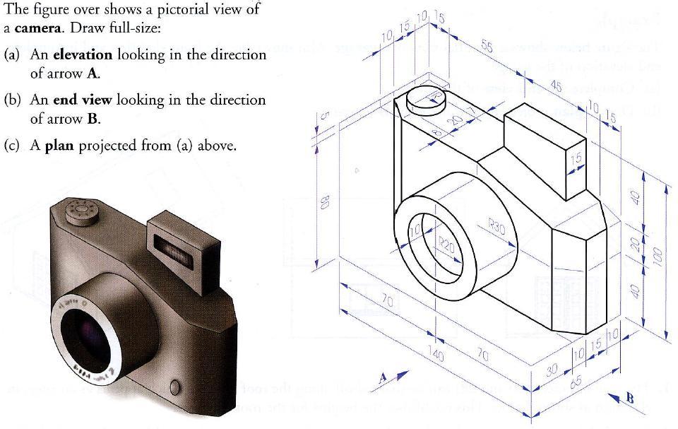
12 Orthographic Projection 2 You have already learned about Orthographic Projection in 1 st Year and how to represent a three-dimensional object on a plane surface. This new chapter shows you how to do this with different shaped objects, like the cone and cylinder below. Notice how the curved surface of the cylinder appears as a rectangle in the elevation and the curved surface of the cone appears as a triangle.
13 Orthographic Projection 2 Example: A Ribena Bottle is shown below. What will the plan look like? What will the elevation look like? Draw a plan and elevation of the bottle.
14 Orthographic Projection 2 Sheet 1 - Title: School Bag
15
16
17
18

19

20

21 Orthographic Projection 2 Sheet 2 - Title: Kitchen Scales

22 Orthographic Projection 2 Rule: The point of intersection between a line and a plane can be determined in a view in which the plane appears as an edge. Using this rule we will complete the following drawing.
23
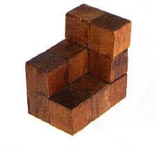
24 1. The elevation and outline of the end view are drawn. 2. The sloped surface appears as an edge or line in the end view. Therefore the height of each step can be projected to intersect this surface in the end view. 3. Now that the depth of each step has been determined the plan can be projected as usual. Orthographic Projection 2
25 Orthographic Projection 2 Sheets 3 & 4- Title: Edge View Orthographics
26
27 Orthographic Projection 2 The following example shows how to complete a plan, elevation and end view when a view cannot be completed in full to begin with.
28 Orthographic Projection 2 1. The incomplete elevation and the entire end view are drawn. 2. The plan is then projected as normal. 3. The upper inclined surface appears as an edge in the plan. Then the remaining lines on the object can be projected from the end view to intersect this line in the plan. 4. Now that the lengths of these lines have been determined they can be projected to the elevation and the drawing completed. Elevation Plan End Elevation
29 Orthographic Projection 2 1. The incomplete elevation and the entire end view are drawn. 2. The plan is then projected as normal. 3. The upper inclined surface appears as an edge in the plan. Then the remaining lines on the object can be projected from the end view to intersect this line in the plan. 4. Now that the lengths of these lines have been determined they can be projected to the elevation and the drawing completed. Elevation Plan End Elevation
30 Orthographic Projection 2 These lads will do a recap on Orthographic Projection for us!

31 Orthographic Projection 2

32 Sheet 5 - Title: Component Orthographic Projection 2

33 A B C DD E F G H I J K L M N O P Q R S T

34 Orthographic Projection 2 Homework 1 - Title: Platform

35 Orthographic Projection 2 Homework 2- Title: Metal Component
36

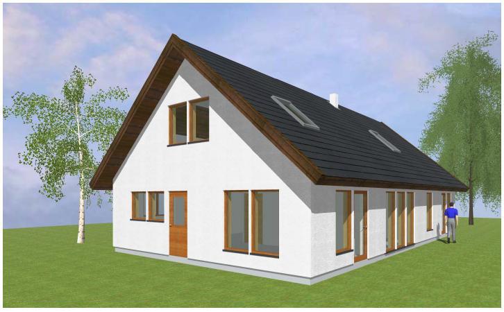
37 Orthographic Projection 2 This slide deals with the topic of True Lengths and how we find them in Orthographic Projection. What is a true length? Take a look at the drawing below and see if you can spot where you need to find the true length in order to complete the drawing.
38 1. The true lengths (20 and 28) can be marked off along the roof surface, which appears as an edge, in elevation as is shown. This establishes the heights for the roof windows. 2. These heights can now be projected to end view and plan where relevant widths and heights can be marked off. Orthographic Projection 2 The true length of any line can be determined if we look at 90 to that line
39

40 Sheet 6 - Title: Package Orthographic Projection 2
41
42
43

44 Orthographic Projection 2 Sectional Views: An object with internal detail can be shown more clearly if a sectional view is drawn. 1. Imagine that the object is cut by an imaginary cutting plane, below left. 2. Imagine the portion of the object nearest you is removed, below centre, 3. The remaining part of the object is projected in the normal manner to show a sectional view, below right.
45 Orthographic Projection 2 The arrows, which are perpendicular to the cutting plane, indicate the viewing direction. In sectional views it is normal practice to hatch the cut surface (section) with equally spaced lights lines at 45

46 Orthographic Projection 2 Recap on Orthographic Projection
47 Orthographic Projection 2 Where is it used? Why is it used? Who used it?
48
49
50
51
52
53
54

55 A B C D D E F G H I J K L M N O P Q R S T
56
57

58 Title: Platform Orthographic Projection 2
59
60
61 If the plan of a cylinder is a circle, what does the elevation look like? PLAN

62 If the plan of a cylinder is a circle, what does the elevation look like? PLAN
63

64
65
66 40 1. Draw the plan and elevation of the cut cylinder. 2. Draw the End View looking in the direction of the arrow 80
67
68 Brief Recap over orthographic projection exercise Sketch the model of the house you see on the table

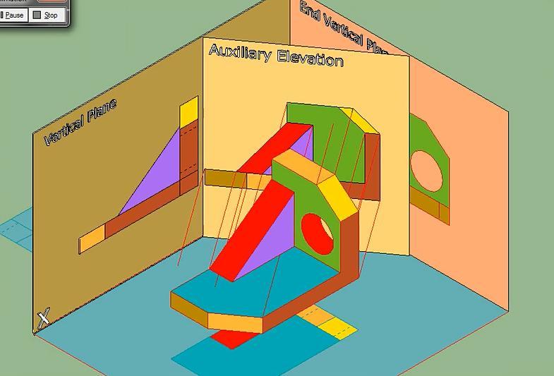
69 What do you think the word Auxiliary means? aqs=chrome..69i57j0l5.3559j0j7&sourceid=chrome&espv=210&es_sm= 93&ie=UTF-8#q=what+does+auxiliary+mean
70 Are these plan or elevation views? Elevation views


71 Are these plan or elevation views? Auxiliary Elevation View

72 Auxiliary Elevation Viewing Direction
73
74

75
76
77
Chapter 5 SECTIONS OF SOLIDS 5.1 INTRODUCTION
 Chapter 5 SECTIONS OF SOLIDS 5.1 INTRODUCTION We have studied about the orthographic projections in which a 3 dimensional object is detailed in 2-dimension. These objects are simple. In engineering most
Engineering Graphics, Class 8 Orthographic Projection. Mohammad I. Kilani. Mechanical Engineering Department University of Jordan
 Engineering Graphics, Class 8 Orthographic Projection Mohammad I. Kilani Mechanical Engineering Department University of Jordan Multi view drawings Multi view drawings provide accurate shape descriptions
Develop an Interior perspective from a floor plan using 2 points. using orthographic projection techniques
 Develop an Interior perspective from a floor plan using 2 points using orthographic projection techniques Obtain a floor of the space to be drawn Digital or hand drawn plan Plan must be to scale Often
Describing an Angle Bracket
 Basics of Drafting Describing an Angle Bracket Orthographic Projection Orthographic drawings represent three dimensional objects in three separate views arranged in a standard manner. Orthographic Views
Multiview Drawing. Definition: Graphical representation of a 3- dimensional object on one plane (sheet of paper) using two or more views.
 using two or more views.") Multiview Drawing Definition: Graphical representation of a 3- dimensional object on one plane (sheet of paper) using two or more views. Multiview Drawing Another name for multiview drawing is orthographic
Multiview Drawing Definition: Graphical representation of a 3- dimensional object on one plane (sheet of paper) using two or more views. Multiview Drawing Another name for multiview drawing is orthographic
GE 6152 ENGINEERING GRAPHICS
 GE 6152 ENGINEERING GRAPHICS UNIT - 4 DEVELOPMENT OF SURFACES Development of lateral surfaces of simple and truncated solids prisms, pyramids, cylinders and cones - Development of lateral surfaces of solids
1 ISOMETRIC PROJECTION SECTION I: INTRODUCTION TO ISOMETRIC PROJECTION
 1 ISOMETRIC PROJECTION SECTION I: INTRODUCTION TO ISOMETRIC PROJECTION Orthographic projection shows drawings of an object in a two-dimensional format, with views given in plan, elevation and end elevation
Multi-View Drawing Review
 Multi-View Drawing Review Sacramento City College EDT 300/ENGR 306 EDT 300 / ENGR 306 - Chapter 5 1 Objectives Identify and select the various views of an object. Determine the number of views needed to
APJ ABDUL KALAM TECHNOLOGICAL UNIVERSITY SECOND SEMESTER B.TECH DEGREE EXAMINATION, MAY PART A Answer ANY Two questions. 10 marks each.
 B B2B111 Pages: 2 Reg. No. Name: SECOND SEMESTER B.TECH DEGREE EXAMINATION, MAY 2017 Max.Marks:50 Course Code: BE110 Duration:3Hours Answer ANY Two questions. 10 marks each. 1. A line AB 100 mm long and
ENGINEERING DRAWING. UNIT III - Part A
 DEVELOPMENT OF SURFACES: ENGINEERING DRAWING UNIT III - Part A 1. What is meant by development of surfaces? 2. Development of surfaces of an object is also known as flat pattern of the object. (True/ False)
Perspective Notes 8 th Grade Art
 Perspective Notes 8 th Grade Art Perspective Perspective is the representation of three-dimensional objects on a flat twodimensional surface. In perspective drawing, objects are made to recede in space
Unit-5 ISOMETRIC PROJECTION
 Unit-5 ISOMETRIC PROJECTION Importance Points in Isometric: 1. For drawing the isometric, the object must be viewed such that either the front -right or the left edges becomes nearest. 2. All vertical
Multiviews and Auxiliary Views
 Multiviews and Auxiliary Views Multiviews and Auxiliary Views Objectives Explain orthographic and multiview projection. Identifying the six principal views. Apply standard line practices to multiviews
Understanding Projection Systems
 Understanding Projection Systems A Point: A point has no dimensions, a theoretical location that has neither length, width nor height. A point shows an exact location in space. It is important to understand
Auxiliary Elevations and Plans
 Chapter 18 uxiliary Elevations and Plans uxiliary Elevations The pictorial view of the thatched cottage shown below indicates how the front elevation is: (i) Obtained from a viewing direction looking in
I B.TECH- I SEMESTER DEPARTMENT OF MECHANICAL ENGINEERING ENGINEERING DRAWING
 I B.TECH- I SEMESTER DEPARTMENT OF MECHANICAL ENGINEERING ENGINEERING DRAWING ENGINEERING DRAWING UNIT-V DEFINITIONS: Axonometric Trimetric Dimetric Isometric It is a parallel technique used to create
Copyrighted Material. Copyrighted Material. Copyrighted. Copyrighted. Material
 Engineering Graphics ORTHOGRAPHIC PROJECTION People who work with drawings develop the ability to look at lines on paper or on a computer screen and "see" the shapes of the objects the lines represent.
ISOMETRIC PROJECTION. Contents. Isometric Scale. Construction of Isometric Scale. Methods to draw isometric projections/isometric views
 ISOMETRIC PROJECTION Contents Introduction Principle of Isometric Projection Isometric Scale Construction of Isometric Scale Isometric View (Isometric Drawings) Methods to draw isometric projections/isometric
Add labels to the sides...
 Orthographic Drawings Orthographic Projection A projection on a plane, using lines perpendicular to the plane Graphic communications has many forms. Orthographics is one such form. It was developed as
ORTHOGRAPHIC PROJECTION
 ORTHOGRAPHIC PROJECTION INTRODUCTION Any object has three dimensions, that is, length, width and thickness. A projection is defined as a representation of an object on a two dimensional plane. The projections
4. Draw the development of the lateral surface of the part P of the cylinder whose front view is shown in figure 4. All dimensions are in cm.
 Code No: Z0122 / R07 Set No. 1 I B.Tech - Regular Examinations, June 2009 ENGINEERING GRAPHICS ( Common to Civil Engineering, Mechanical Engineering, Chemical Engineering, Bio-Medical Engineering, Mechatronics,
Short Introduction to Planes Not on EL VPs (Pitches and Inclined Planes)
") Short Introduction to Planes Not on VPs (Pitches and Inclined Planes) Planes Not on VPs (Pitches and Inclined Planes) Print this page to use as your source drawing guide Short Introduction to Planes Not
Short Introduction to Planes Not on VPs (Pitches and Inclined Planes) Planes Not on VPs (Pitches and Inclined Planes) Print this page to use as your source drawing guide Short Introduction to Planes Not
Trade of Metal Fabrication. Module 6: Fabrication Drawing Unit 13: Parallel Line Development Phase 2
 Trade of Metal Fabrication Module 6: Fabrication Drawing Unit 13: Parallel Line Development Phase 2 Table of Contents List of Figures... 4 List of Tables... 5 Document Release History... 6 Module 6 Fabrication
ENGINEERING GRAPHICS UNIT V ISOMETRIC PROJECTION PERSPECTIVE PROJECTION
 ENGINEERING GRAPHICS UNIT V ISOMETRIC PROJECTION PERSPECTIVE PROJECTION 1.PICTORIAL PROJECTIONS To visualize the shape of the whole object in its 3- D form, all the two or three orthographic views of the
Orthographic Projection
 Orthographic Projection Why Orthographic Projection is used in technical drawing Orthographic projection is a method of producing a number of separate two-dimensional inter-related views, which are mutually
Engineering Graphics Essentials with AutoCAD 2015 Instruction
 Kirstie Plantenberg Engineering Graphics Essentials with AutoCAD 2015 Instruction Text and Video Instruction Multimedia Disc SDC P U B L I C AT I O N S Better Textbooks. Lower Prices. www.sdcpublications.com
BOARD DIPLOMA EXAMINATION, (C 14) APRIL/MAY 2015 DECE FIRST YEAR EXAMINATION ENGINEERING DRAWING
 APRIL/MAY 2015 DECE FIRST YEAR EXAMINATION ENGINEERING DRAWING") C 14 CHPC/EC/PET 107 4037 BOARD DIPLOMA EXAMINATION, (C 14) APRIL/MAY 2015 DECE FIRST YEAR EXAMINATION ENGINEERING DRAWING Time : 3 hours ] [ Total Marks : 60 Instructions : (1) Answer all questions. PART
C 14 CHPC/EC/PET 107 4037 BOARD DIPLOMA EXAMINATION, (C 14) APRIL/MAY 2015 DECE FIRST YEAR EXAMINATION ENGINEERING DRAWING Time : 3 hours ] [ Total Marks : 60 Instructions : (1) Answer all questions. PART
ENGINEERING GRAPHICS ESSENTIALS
 ENGINEERING GRAPHICS ESSENTIALS with AutoCAD 2012 Instruction Introduction to AutoCAD Engineering Graphics Principles Hand Sketching Text and Independent Learning CD Independent Learning CD: A Comprehensive
Technological Design Mr. Wadowski. Orthographic & Isometric Drawing Lesson
 Technological Design Mr. Wadowski Orthographic & Isometric Drawing Lesson TOPICS Working Drawings, Isometric Drawings & Orthographic Drawings Glass box concept Multiview projection Orthographic projection
Cross Sections of Three-Dimensional Figures
 Domain 4 Lesson 22 Cross Sections of Three-Dimensional Figures Common Core Standard: 7.G.3 Getting the Idea A three-dimensional figure (also called a solid figure) has length, width, and height. It is
Design & Communication Graphics
 L.84/85 Design & Communication Graphics Marking Scheme Ordinary Pg. 3 Higher Pg. 12 2013 L.84/85_MS 1/20 2013 L.84/85_MS 2/20 SECTION A - Core - Answer Any Three of the questions on this A3 sheet A-1.
Perspective Sketching
 Perspective Sketching Perspective Drawings A perspective drawing offers the most realistic three-dimensional view of all the pictorial methods, because it portrays the object in a manner that is most similar
.VP CREATING AN INVENTED ONE POINT PERSPECTIVE SPACE
 PAGE ONE Organize an invented 1 point perspective drawing in the following order: 1 Establish an eye level 2 Establish a Center Line Vision eye level vision Remember that the vanishing point () in one
At the conclusion of this unit you should be able to accomplish the following with a 70% accuracy
 7 Multiview Drawing OBJECTIVES At the conclusion of this unit you should be able to accomplish the following with a 70% accuracy 1. explain the importance of mulitview drawing as a communication tool far
INSTITUTE OF AERONAUTICAL ENGINEERING
 Course Name Course Code Class Branch INSTITUTE OF AERONAUTICAL ENGINEERING Dundigal, Hyderabad - 500 043 MECHANICAL ENGINEERING TUTORIAL QUESTION BANK : ENGINEERING DRAWING : A10301 : I - B. Tech : Common
AUXILIARY VIEWS C H A P T E R N I N E
 AUXILIARY VIEWS C H A P T E R N I N E Giesecke, Hill, Spencer, Dygdon, Novak, Lockhart, Goodman 1 OBJECTIVES 1. Create an auxiliary view from orthographic views. 2. Draw folding lines or reference-plane
ORTHOGRAPHIC PROJECTIONS. Ms. Sicola
 ORTHOGRAPHIC PROJECTIONS Ms. Sicola Objectives List the six principal views of projection Sketch the top, front and right-side views of an object with normal, inclined, and oblique surfaces Objectives
GOVERNMENT POLYTECHNIC, VALSAD MECHANICAL ENGINEERING DEPARTMENT ASSIGNMENT SUB: MECHANICAL DRAFTING (C321901) TERM:172
 TERM:172") GOVERNMENT POLYTECHNIC, VALSAD MECHANICAL ENGINEERING DEPARTMENT ASSIGNMENT SUB: MECHANICAL DRAFTING (C321901) TERM:172 1) When all the dimension are placed above the dimension line, it is called (a) Aligned
GOVERNMENT POLYTECHNIC, VALSAD MECHANICAL ENGINEERING DEPARTMENT ASSIGNMENT SUB: MECHANICAL DRAFTING (C321901) TERM:172 1) When all the dimension are placed above the dimension line, it is called (a) Aligned
CLASS views from detail on a grid paper. (use appropriate line types to show features) - Optional views. Turn in for grading on class 6 (06/04)
 - Optional views. Turn in for grading on class 6 (06/04)") CLASS 4 Review: - Projections - Orthographic projections Lab: - 3 views from detail on a grid paper. (use appropriate line types to show features) - Optional views. Turn in for grading on class 6 (06/04)
CLASS 4 Review: - Projections - Orthographic projections Lab: - 3 views from detail on a grid paper. (use appropriate line types to show features) - Optional views. Turn in for grading on class 6 (06/04)
Chapter 4 ORTHOGRAPHIC PROJECTION
 Chapter 4 ORTHOGRAPHIC PROJECTION 4.1 INTRODUCTION We, the human beings are gifted with power to think. The thoughts are to be shared. You will appreciate that different ways and means are available to
ENGINEERING GRAPHICS
 ENGINEERING GRAPHICS CLASS - XII (046) DESIGN OF THE QUESTION PAPER Time : 3 Hrs Max. Marks : 70 The weightage of the distribution of marks over different contents of the question paper shall be as follows:
Drawing Standards & Conventions for IDD
 Drawing Standards & Conventions for IDD This document consists of a set of standards that have been developed to maintain a consistency in Interior Decoration and Design students work. The standards are
JUNIOR CERTIFICATE 2008 MARKING SCHEME TECHNICAL GRAPHICS HIGHER LEVEL
 JUNIOR CERTIFICATE 2008 MARKING SCHEME TECHNICAL GRAPHICS HIGHER LEVEL Sections A and B Section A - any ten questions from this Section Q1 12 Four diagrams, 3 marks for each correct label. Q2 12 3 height
Design & Communication Graphics Higher Level Section A (60 marks)
") 1 L.85A Pre-Leaving Certificate Examination, 2012 Design & Communication Graphics Higher Level Section A (60 marks) Time: 3 Hours This examination is divided into three sections: SECTION A SECTION B SECTION
1 L.85A Pre-Leaving Certificate Examination, 2012 Design & Communication Graphics Higher Level Section A (60 marks) Time: 3 Hours This examination is divided into three sections: SECTION A SECTION B SECTION
ORTHOGRAPHIC PROJECTION
 ORTHOGRAPHIC PROJECTION C H A P T E R S I X OBJECTIVES 1. Recognize and the symbol for third-angle projection. 2. List the six principal views of projection. 3. Understand which views show depth in a drawing
ME 111: Engineering Drawing
 ME 111: Engineering Drawing Lecture 5 12-08-2011 Orthographic projection and Projection of Points Indian Institute of Technology Guwahati Guwahati 781039 1 Orthographic Projection A parallel projection
Blueprint Reading Basics For Welding Fabrication
 Blueprint Reading Basics For Welding Fabrication 9/14/2011 1 Definitions of Lines Lines are the basic communication tool used in blueprints. Listed below are examples of the most common lines used in blueprints
ENGINEERING DRAWING I
 INSTITUTE OF ENGINEERING DEPARTMENT OF MECHANICAL ENGINEERING ENGINEERING DRAWING I [TUTORIAL SHEETS] 1 CONTENTS Sheet No. 1: Technical Lettering 3 Sheet No. 2: Plane Geometrical Construction 5 Sheet No.
Set No - 1 I B. Tech I Semester Regular/Supplementary Examinations Jan./Feb ENGINEERING DRAWING (EEE)
") Set No - 1 I B. Tech I Semester Regular/Supplementary Examinations Jan./Feb. - 2015 ENGINEERING DRAWING Time: 3 hours (EEE) Question Paper Consists of Part-A and Part-B Answering the question in Part-A
Set No - 1 I B. Tech I Semester Regular/Supplementary Examinations Jan./Feb. - 2015 ENGINEERING DRAWING Time: 3 hours (EEE) Question Paper Consists of Part-A and Part-B Answering the question in Part-A
C A R I B B E A N E X A M I N A T I O N S C O U N C I L REPORT ON CANDIDATES WORK IN THE SECONDARY EDUCATION CERTIFICATE EXAMINATION MAY/JUNE 2010
 C A R I B B E A N E X A M I N A T I O N S C O U N C I L REPORT ON CANDIDATES WORK IN THE SECONDARY EDUCATION CERTIFICATE EXAMINATION MAY/JUNE 2010 TECHNICAL DRAWING GENERAL PROFICIENCY Copyright 2010 Caribbean
2 Point Perspective. Point Perspective. Slide 1 of 40: Requirements
 2 Slide 1 of 40: Requirements Before we move on to How to draw a two point perspective, you will require a plan and an elevation of the Object you wish to draw perspective of. With a more complex object
ENGINEERING GRAPHICS 1E9
 Lecture 3 Monday, 15 December 2014 1 ENGINEERING GRAPHICS 1E9 Lecture 3: Isometric Projections Lecture 3 Monday, 15 December 2014 2 What is ISOMETRIC? It is a method of producing pictorial view of an object
Chapter 2: Dimensioning Basic Topics Advanced Topics Exercises
 Chapter 2: Dimensioning Basic Topics Advanced Topics Exercises Dimensioning: Basic Topics Summary 2-1) Detailed Drawings 2-2) Learning to Dimension 2-3) Dimension Appearance and Techniques. 2-4) Dimensioning
Mechanical Drawing. Unit 2 Study Guide for Chapters 6-10
 Mechanical Drawing Unit 2 Study Guide for Chapters 6-10 Chapter 6 Multiview Drawing Section 6.1 Understanding Orthographic Projection A. Technical Drawing: How can a technical drawing give more accurate
Interpretation of Drawings. An Introduction to the Basic Concepts of Creating Technical Drawings
 Interpretation of Drawings An Introduction to the Basic Concepts of Creating Technical Drawings Introduction In the design process drawings are the main way in which information about an object or product
Lecture 6 ( ): Theory of Multi-view Orthographic Projections
: Theory of Multi-view Orthographic Projections") Lecture 6 (06.08.12): Theory of Multi-view Orthographic Projections Dr. Sharad Gokhale Civil Engineering Department, IIT Guwahati 208, M-Block, Academic Complex Email: sharadbg@iitg.ernet.in Telephone
Lecture 6 (06.08.12): Theory of Multi-view Orthographic Projections Dr. Sharad Gokhale Civil Engineering Department, IIT Guwahati 208, M-Block, Academic Complex Email: sharadbg@iitg.ernet.in Telephone
Solutions to Exercise problems
 Brief Overview on Projections of Planes: Solutions to Exercise problems By now, all of us must be aware that a plane is any D figure having an enclosed surface area. In our subject point of view, any closed
A Concise Introduction to Engineering Graphics
 Concise Introduction to Engineering Graphics ourth Edition Including Worksheet Series imothy J. Sexton, Professor Department of Industrial echnology Ohio University ONUS ook on CD: ECHNICL GRPHICS Meyers,
JUNIOR CERTIFICATE 2009 MARKING SCHEME TECHNICAL GRAPHICS HIGHER LEVEL
 . JUNIOR CERTIFICATE 2009 MARKING SCHEME TECHNICAL GRAPHICS HIGHER LEVEL Sections A and B Section A any ten questions from this section Q1 12 Four diagrams, 3 marks for each correct label. Q2 12 2 marks
UNIT 5a STANDARD ORTHOGRAPHIC VIEW DRAWINGS
 UNIT 5a STANDARD ORTHOGRAPHIC VIEW DRAWINGS 5.1 Introduction Orthographic views are 2D images of a 3D object obtained by viewing it from different orthogonal directions. Six principal views are possible
Drawing sheet: - The various size of the drawing sheet used for engineering drawing as per IS Are listed in the table
 Dronacharya Group of Institutions, Greater Noida Computer Aided Engineering Graphics (CAEG) (NCE 151/251) List of Drawing Sheets: 1. Letter writing & Dimensioning. 2. Projection of Points & Lines. 3. Projection
DELHI TECHNOLOGICAL UNIVERSITY ENGINEERING GRAPHICS LAB MANUAL
 DELHI TECHNOLOGICAL UNIVERSITY ENGINEERING GRAPHICS LAB MANUAL NAME: - ROLL NO: - GROUP: - BRANCH: - GROUP TEACHER: Page 1 www.rooplalrana.com 1 GENERAL INSTRUCTIONS FOR ENGG. GRAPHICS LAB 1) Students
Sketching Fundamentals
 Sketching Fundamentals Learning Outcome When you complete this module you will be able to: Make basic engineering sketches of plant equipment. Learning Objectives Here is what you will be able to do when
ENGR 1182 Exam 1 First Mid Term Exam Study Guide and Practice Problems
 Spring Semester 2016 ENGR 1182 Exam 1 First Mid Term Exam Study Guide and Practice Problems Disclaimer Problems in this study guide resemble problems relating mainly to the pertinent homework assignments.
PROJECTIONS PARALLEL CONICAL PROJECTIONS PROJECTIONS OBLIQUE ORTHOGRAPHIC PROJECTIONS PROJECTIONS
 PROJECTIONS CONICAL PROJECTIONS PARALLEL PROJECTIONS OBLIQUE PROJECTIONS ORTHOGRAPHIC PROJECTIONS ISOMETRIC MULTI-VIEW an object; The Description of Forms Behind every drawing of an object is space relationship
Introduction to Sheet Metal Features SolidWorks 2009
 SolidWorks 2009 Table of Contents Introduction to Sheet Metal Features Base Flange Method Magazine File.. 3 Envelopment & Development of Surfaces.. 14 Development of Transition Pieces.. 23 Conversion to
Technical Graphics Higher Level
 Coimisiún na Scrúduithe Stáit State Examinations Commission Junior Certificate Examination 2005 Technical Graphics Higher Level Marking Scheme Sections A and B Section A Q1. 12 Four diagrams, 3 marks for
Eureka Math. Grade K, Module 2. Student File_A. Contains copy-ready classwork and homework as well as templates (including cut outs)
") A Story of Units Eureka Math Grade K, Module 2 Student File_A Contains copy-ready classwork and homework as well as templates (including cut outs) Published by the non-profit Great Minds. Copyright 2015
A Story of Units Eureka Math Grade K, Module 2 Student File_A Contains copy-ready classwork and homework as well as templates (including cut outs) Published by the non-profit Great Minds. Copyright 2015
Orthographic Projection
 ENG3000 Orthographic Projection 1 Session Objectives To understand the basic principles of orthographic projection To be able to construct orthographic views of simple objects To visualize 3 D objects
Civil Engineering Drawing
 Civil Engineering Drawing Third Angle Projection In third angle projection, front view is always drawn at the bottom, top view just above the front view, and end view, is drawn on that side of the front
ENGINEERING GRAPHICS
 ENGINEERING GRAPHICS Course Structure Units Topics Marks Unit I Plane Geometry 16 1 Lines, angles and rectilinear figures 2 Circles and tangents 3 Special curves: ellipse, parabola, involute, cycloid.
UNIT I PLANE CURVES AND FREE HAND SKETCHING CONIC SECTIONS
 UNIT I PLANE CURVES AND FREE HAND SKETCHING CONIC SECTIONS Definition: The sections obtained by the intersection of a right circular cone by a cutting plane in different positions are called conic sections
Graphical Communication
 Chapter 9 Graphical Communication mmm Becoming a fully competent engineer is a long yet rewarding process that requires the acquisition of many diverse skills and a wide body of knowledge. Learning most
technical drawing
 technical drawing school of art, design and architecture nust spring 2011 http://www.youtube.com/watch?v=q6mk9hpxwvo http://www.youtube.com/watch?v=bnu2gb7w4qs Objective abstraction - axonometric view
Change of position method:-
 Projections of Planes PROJECTIONS OF PLANES A plane is a two dimensional object having length and breadth only. Thickness is negligible. Types of planes 1. Perpendicular plane which have their surface
Autodesk Inventor Module 17 Angles
 Inventor Self-paced ecourse Autodesk Inventor Module 17 Angles Learning Outcomes When you have completed this module, you will be able to: 1 Describe drawing inclined lines, aligned and angular dimensions,
TOY TRUCK. Figure 1. Orthographic projections of project.
 TOY TRUCK Prepared by: Harry Hawkins The following project is of a small, wooden toy truck. This exercise will provide you with the procedure for constructing the various parts of the design then assembling
Student Name: Teacher: Date: District: Rowan. Assessment: 9_12 T and I IC61 - Drafting I Test 1. Description: Unit C - Sketching - Test 2.
 Student Name: Teacher: Date: District: Rowan Assessment: 9_12 T and I IC61 - Drafting I Test 1 Description: Unit C - Sketching - Test 2 Form: 501 1. The most often used combination of views includes the:
 6.1 INTRODUCTION Chapter 6 ORTHOGRAPHIC PROJECTIONS OF SIMPLE MACHINE BLOCKS We have already made you aware of many simple geometrical shapes (laminae), projected on such planes (vertical plane, horizontal
Auxiliary view KCEC1101
 Auxiliary view KCEC1101 Introduction There are times when one of the six principal views will not completely describe an object. This is especially true when there are inclined or oblique planes or features
Drawing Types & Construction Drawings
 Drawing Types & Construction Drawings Building projects require several types of specialised drawings. This collection of drawings, known as a project set, includes: Location Plan Site Plan Floor Plan
SAMPLE QUESTION PAPER III ENGINEERING GRAPHICS (046) Time Allowed: 3 hours Maximum Marks: 70
 Time Allowed: 3 hours Maximum Marks: 70") SAMPLE QUESTION PAPER III ENGINEERING GRAPHICS (046) Time Allowed: 3 hours Maximum Marks: 70 Note: (i) Attempt all the questions. (ii) Use both sides of the drawing sheet, if necessary. (iii) All dimensions
SAMPLE QUESTION PAPER III ENGINEERING GRAPHICS (046) Time Allowed: 3 hours Maximum Marks: 70 Note: (i) Attempt all the questions. (ii) Use both sides of the drawing sheet, if necessary. (iii) All dimensions
TPCT s College of Engineering, Osmanabad. Laboratory Manual. Engineering Graphics. For. First Year Students. Manual Prepared by B. G.
 TPCT s College of Engineering, Osmanabad Laboratory Manual Engineering Graphics For First Year Students Manual Prepared by B. G. Kadam Author COE, Osmanabad TPCT s College of Engineering Solapur Road,
6. Draw the isometric view of a cone 40 mm diameter and axis 55 mm long when its axis is horizontal. Draw isometric scale. [16]
![6. Draw the isometric view of a cone 40 mm diameter and axis 55 mm long when its axis is horizontal. Draw isometric scale. [16]](/thumbs/85/92603403.jpg "6. Draw the isometric view of a cone 40 mm diameter and axis 55 mm long when its axis is horizontal. Draw isometric scale. [16]") Code No: R05010107 Set No. 1 I B.Tech Supplimentary Examinations, Aug/Sep 2007 ENGINEERING GRAPHICS ( Common to Civil Engineering, Mechanical Engineering, Mechatronics, Metallurgy & Material Technology,
Code No: R05010107 Set No. 1 I B.Tech Supplimentary Examinations, Aug/Sep 2007 ENGINEERING GRAPHICS ( Common to Civil Engineering, Mechanical Engineering, Mechatronics, Metallurgy & Material Technology,
Glass Box Projection. Gives you 6 sides to view of an object. 10/2/14 2
 2D Drawings Glass Box Projection Gives you 6 sides to view of an object. 10/2/14 2 We can simplify this for some objects to 3 views Glass Box Approach Glass Box Approach Glass Box Approach Glass Box Approach
ENGINEERING GRAPHICS ESSENTIALS
 ENGINEERING GRAPHICS ESSENTIALS Text and Digital Learning KIRSTIE PLANTENBERG FIFTH EDITION SDC P U B L I C AT I O N S Better Textbooks. Lower Prices. www.sdcpublications.com ACCESS CODE UNIQUE CODE INSIDE
Sketching in SciTech. What you need to know for graphic communication
 Sketching in SciTech What you need to know for graphic communication Sketching in your Logbook Use pencil Take up the WHOLE PAGE Label things 1. Proportion Each part of the sketch is the right size,
DESIGN & COMMUNICATION GRAPHICS Conic Sections 1
 The projections of a right cone are shown below. The traces of a simply inclined plane VTH are also given. The plane is parallel to an element of the cone. The intersection of a plane and a right cone
Learning Outcomes. Students should be able to: Demonstrate an understanding of the planes of reference
 Orthographic projection is a means of representing a three-dimensional (3D) object in two dimensions (2D). It is the projection by parallel rays onto a plane at right angles to the rays. Demonstrate an
Name: Period: THE ELEMENTS OF ART
 Name: Period: THE ELEMENTS OF ART Name: Period: An element of art that is used to define shape, contours, and outlines, also to suggest mass and volume. It may be a continuous mark made on a surface with
ENGINEERING DRAWING. 1. Set squares are used to draw different angles. What is the angel a formed by the 45⁰ set square? Give a brief answer.
 ENGINEERING DRAWING 1. Set squares are used to draw different angles. What is the angel a formed by the 45⁰ set square? Give a brief answer. 2. Which is the correct method of hatching a plane surface?
Second Semester Session Shri Ramdeobaba College of Engineering & Management, Nagpur. Department of Mechanical Engineering
 Second Semester Session- 2017-18 Shri Ramdeobaba College of Engineering & Management, Nagpur. Department of Mechanical Engineering Engineering Drawing Practical Problem Sheet Sheet No.:- 1. Scales and
SolidWorks Design & Technology
 SolidWorks Design & Technology Training Course at PHSG Ex 5. Lego man Working with part files 8mm At first glance the Lego man looks complicated but I hope you will see that if you approach a project one
Tapered or Conical Tee
 TRADE OF Industrial Insulation PHASE 2 Module 2 Geometry & Pattern Development UNIT: 9 Produced by In cooperation with subject matter expert: Michael Kelly SOLAS 2014 Table of Contents Unit Objective...
DMT113 Engineering Drawing. Chapter 3 Stretch System
 DMT113 Engineering Drawing Chapter 3 Stretch System Contents Theory & Multiview Planes 6 Principle Views Multiview Sketching Technique & Perspective First & Third Angle Multiview Representations Theory
Shapes and Patterns. Lesson 1 Exploring Plane Shapes (Part 1) Name the shapes. triangle circle rectangle square Color the squares.
 Name the shapes. triangle circle rectangle square Color the squares.") CHAPTER 5 Shapes and Patterns Lesson 1 Exploring Plane Shapes (Part 1) Name the shapes. triangle circle rectangle square 1. 2. 3. 4. Color the squares. 5. Extra Practice 1A 71 Color the shapes that are
CHAPTER 5 Shapes and Patterns Lesson 1 Exploring Plane Shapes (Part 1) Name the shapes. triangle circle rectangle square 1. 2. 3. 4. Color the squares. 5. Extra Practice 1A 71 Color the shapes that are
7048 CDT: DESIGN AND COMMUNICATION
 www.onlineexamhelp.com www.onlineexamhelp.com UNIVERSITY OF CAMBRIDGE INTERNATIONAL EXAMINATIONS GCE Ordinary Level MARK SCHEME for the October/November 008 question paper 7048 CDT: DESIGN AND COMMUNICATION
Orthographic Drawing (Architectural Board Drafting)
") Design and Drafting Description In this activity, the teacher will introduce orthographic projection, in which a multi-view drawing shows how the sides of an object are related to each another. Students
Design and Drafting Description In this activity, the teacher will introduce orthographic projection, in which a multi-view drawing shows how the sides of an object are related to each another. Students
elements of design worksheet
 elements of design worksheet Line Line: An element of art that is used to define shape, contours, and outlines, also to suggest mass and volume. It may be a continuous mark made on a surface with a pointed
Engineering Working Drawings Basics
 Engineering Working Drawings Basics Engineering graphics is an effective way of communicating technical ideas and it is an essential tool in engineering design where most of the design process is graphically