Multiviews and Auxiliary Views
|
|
|
- Wesley Richardson
- 5 years ago
- Views:
Transcription
1 Multiviews and Auxiliary Views
2 Multiviews and Auxiliary Views Objectives Explain orthographic and multiview projection. Identifying the six principal views. Apply standard line practices to multiviews drawings. Create multiviews drawing. Identifying normal, inclined and oblique planes.
3 Multiviews and Auxiliary Views Objectives Representation of geometric entities and features in multiview drawings. Apply visualization by solids and surfaces to multiviews. Create auxiliary views.
4 Projection Theory Projection theory comprises the principles used to represent graphically 3-D objects and structures on 2-D media. Projection methods are developed along two lines: Perspective. Parallel.
5 Projection Theory All projection theory is based on two variables: line of sight (LOS) A line of sight is an imaginary ray of light between an observer's eye and the object. plane of projection. Is an imaginary flat plane upon which the image created by the lines of sight is projected.
6 Perspective Projection In perspective projection, all lines of sight start at a single point and the object is positioned at a finite distance and viewed from a single point.
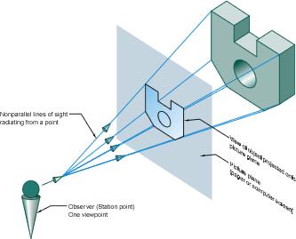
7 Perspective Projection
8 Parallel Projection In parallel projection, all lines of sight are parallel, the object is positioned at infinity and viewed from multiple points on an imaginary line parallel to the object. The 3-D object is transformed into a 2-D representation or a plane of projection that is an imaginary flat plane upon which the image created by the lines of sight is projected.
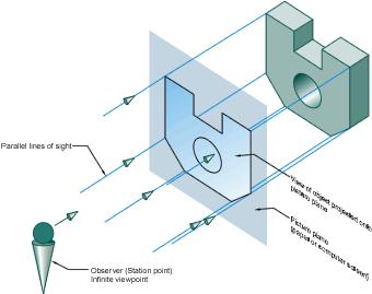
9 Parallel Projection
10 Orthographic Projection Orthographic projection is a parallel projection technique in which the plane of projection is positioned between the observer and the object, and is perpendicular to the parallel lines of sight. Orthographic projection techniques can be used to produce both pictorial and multiview drawings.
11 Orthographic Projection
12 Multiview Projection Multiview projection is an orthographic projection for which the object is behind the plane of projection, and is oriented so only two of its dimensions are shown. Generally three views of an object are drawn, and the features and dimensions in each view accurately represent those of the object.
13 Multiview Projection Frontal Plane of Projection- Front View
14 Multiview Projection Frontal Plane of Projection- Front View Width Height

15 Multiview Projection Planes Horizontal plane of projection-top View Width Depth

16 Multiview Projection Planes Profile plane of projection- Side View Height Depth
17 Multiview Projection Planes Advantages Multiview drawings provide the most accurate description of three dimensional objects and structure for engineering, manufacturing, and construction requirements. True shape and size.

18 Six Principal Views Six mutually perpendicular views. Front view- X Y Top view- Z X Right side view- Z Y Left side view- Z Y Rear view- Y X Bottom view- Z X

19 Six Principal Views Conventional View Placement Three-view multiview drawing. Standard views: Top Front Right side view

20 Six Principal Views Angle projection Third US and Canada First Europe Adjacent Views Related Views Central View
21 Line Conventions Hidden Lines Hidden features are represented by dashed lines. Holes - to locate the limiting elements. Surfaces - to locate the edge view of the surface.

22 Line Conventions Hidden Lines Change of planes - to locate the position of the change of plane or corner.
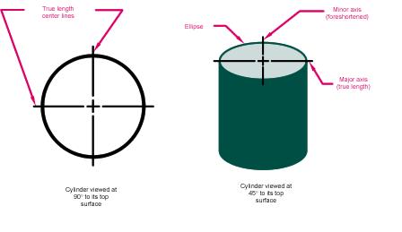
23 Line Conventions Center Lines Center lines are alternate long and short thin dashes and are used for the axes of symmetrical parts and features, such as cylinders and drilled holes.
24 Line Conventions Center Lines Center line usage follows standard drawing practices: Center lines for holes and slots locate limiting elements and any changes in planes. Center lines should not terminate at another line or extend between views. Very short, unbroken center lines may be used to represent the axes of very small holes. Center lines can indicate radial symmetry. Center lines do not break when they cross another line at or near 90 degrees. Center lines can be used as paths of motion.
25
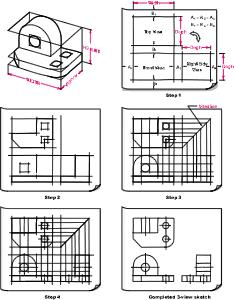
26 Multiview Sketches One-view Two-view Three-view
27
28
29
30 Fundamental Views of Edges edge, or corner, is the intersection of two planes, and is represented as a line on a multiview drawing. A normal edge, or true-length line, is an edge that is parallel to a plane of projection and thus perpendicular to the line of sight.

31 Fundamental Views of Edges An inclined edge, or line, is parallel to a plane of projection, but inclined to the adjacent planes and appears foreshortened in the adjacent views. Features are foreshortened when the lines of sight are not perpendicular to the feature.

32 Fundamental Views of Edges An oblique edge or line, is not parallel to any principal plane of projection; therefore it never appears as a point or in true length in any of the six principal views.
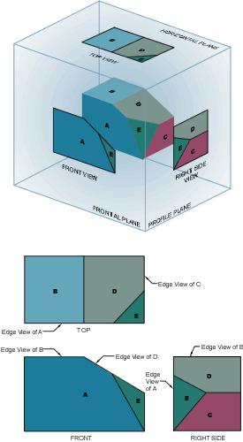
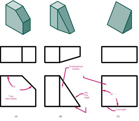
33 Fundamental Views of Planes A normal or principal plane is parallel to one of the principal planes of projection, and therefore is perpendicular to the line of sight. A frontal plane is parallel to the front plane of projection and is true shape and size in the front and back views. (plane A) A horizontal plane is parallel to the horizontal plane of projection and is true shape and size in the top and bottom views. (plane B)
34 Fundamental Views of Planes A profile plane is parallel to the profile plane of projection and is true shape and size in the right and left views. (plane C) A inclined plane is perpendicular to one plane of projection (edge) and inclined to adjacent planes (foreshortened), and cannot be viewed in true size and shape in any of the principal views. (plane D)
35 Fundamental Views of Planes An oblique plane is oblique to all principal planes of projection. An oblique surface does not appear in its true shape or size, or as a line in any of the principal views: instead, an oblique plane always appears foreshortened in any principal view.
36
37
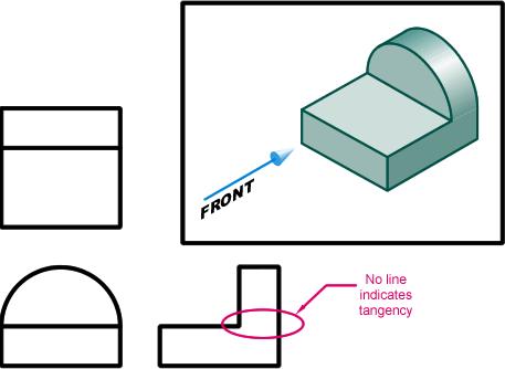
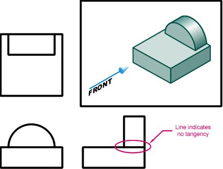
38 Multiview Representation Three dimensional solid objects are represented on 2-D media as points, lines and planes. Points Planes Change of planes Angles Curved surfaces Holes Fillets, Round, Finished surfaces, and Chamfer Runouts Intersecting cylinders Cylinders intersecting Prism and holes
39
40
41
42
43
44
45
46
47
48
49
50
51 Multiview Drawing Visualization Techniques for improving your ability to visualize multiview drawing. Projection studies Physical model construction Adjacent areas Similar shapes Surface labeling Vertex labeling Missing lines Analysis by solids Analysis by surface
52 ANSI Standards for Multiview Drawing and Sketches ANSI standards of multiview drawings form the common language used by engineers and technologists for communication information. Partial Views A partial view shows only what is necessary to completely describe the object. A conventional break line is placed in a location where it does not coincide with a visible or hidden line.
53
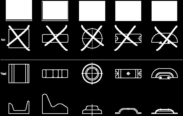
54 ANSI Standards for Multiview Drawing and Sketches Revolution Conventions ANSI revolution conventions allow geometry to be revolved into positions that allow an object to be viewed true size and shape. Objects can be revolved on bolt circles. Inclined arms can also be revolved perpendicular to the line of sight to allow for better visualization of the object. Removed Views
55
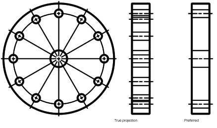
56 Auxiliary View Projections There are times when one of the six principal views will not completely describe an object. This is especially true when there are inclined or oblique planes or features on an object. An auxiliary view is an orthographic view which is projected onto any plane other than the frontal, horizontal, or profile plane.
57
58 Auxiliary View Projections Fold-line Method The object suspended inside a glass box, which has a special or auxiliary plane that is parallel to inclined surface ABCD. The line of sight required to create the auxiliary view is perpendicular to the new projection plane and to surface ABCD.
59
60 Auxiliary View Projections Reference Plane Method Is a variation of the fold-line method. Is a technique that locates a plane relative to the object, instead of suspending the object in a glass box. Auxiliary View Classifications Primary Secondary Tertiary
61 Auxiliary View Projections Applications Reverse construction True length of a line Point view of a line Edge view of a plane True size of a plane
62
63
64 Rules of Orthographic Projection 1. Every point or feature in one view must be aligned on a parallel projector in any adjacent view. 2. Distance between any two points of a feature in a related views must be equal. 3. Features are true length or true size when lines of sight are perpendicular to the feature.
65 Rules of Orthographic Projection 4. Features are foreshortened when the lines of sight are not perpendicular to the feature. 5. Areas that are the same feature will always be similar in configuration from one view to the next, unless view as an edge. 6. Parallel features will always appear parallel in all views.
66 Rules of Orthographic Projection 7. Surfaces that are parallel to the lines of sight will appear on edge and be represented as a line. 8. No two contiguous areas can lie in the same plane.
ORTHOGRAPHIC PROJECTION
 ORTHOGRAPHIC PROJECTION C H A P T E R S I X OBJECTIVES 1. Recognize and the symbol for third-angle projection. 2. List the six principal views of projection. 3. Understand which views show depth in a drawing
DMT113 Engineering Drawing. Chapter 3 Stretch System
 DMT113 Engineering Drawing Chapter 3 Stretch System Contents Theory & Multiview Planes 6 Principle Views Multiview Sketching Technique & Perspective First & Third Angle Multiview Representations Theory
CLASS views from detail on a grid paper. (use appropriate line types to show features) - Optional views. Turn in for grading on class 6 (06/04)
 - Optional views. Turn in for grading on class 6 (06/04)") CLASS 4 Review: - Projections - Orthographic projections Lab: - 3 views from detail on a grid paper. (use appropriate line types to show features) - Optional views. Turn in for grading on class 6 (06/04)
CLASS 4 Review: - Projections - Orthographic projections Lab: - 3 views from detail on a grid paper. (use appropriate line types to show features) - Optional views. Turn in for grading on class 6 (06/04)
Auxiliary view KCEC1101
 Auxiliary view KCEC1101 Introduction There are times when one of the six principal views will not completely describe an object. This is especially true when there are inclined or oblique planes or features
ORTHOGRAPHIC PROJECTIONS. Ms. Sicola
 ORTHOGRAPHIC PROJECTIONS Ms. Sicola Objectives List the six principal views of projection Sketch the top, front and right-side views of an object with normal, inclined, and oblique surfaces Objectives
Multiview Drawing. Definition: Graphical representation of a 3- dimensional object on one plane (sheet of paper) using two or more views.
 using two or more views.") Multiview Drawing Definition: Graphical representation of a 3- dimensional object on one plane (sheet of paper) using two or more views. Multiview Drawing Another name for multiview drawing is orthographic
Multiview Drawing Definition: Graphical representation of a 3- dimensional object on one plane (sheet of paper) using two or more views. Multiview Drawing Another name for multiview drawing is orthographic
MULTIPLE CHOICE QUESTIONS - CHAPTER 6
 MULTIPLE CHOICE QUESTIONS - CHAPTER 6 1. The selection of the front view in executing a multiview drawing of an object is dependent upon the following factors: a. size and shape of the object and their
Engineering Graphics, Class 8 Orthographic Projection. Mohammad I. Kilani. Mechanical Engineering Department University of Jordan
 Engineering Graphics, Class 8 Orthographic Projection Mohammad I. Kilani Mechanical Engineering Department University of Jordan Multi view drawings Multi view drawings provide accurate shape descriptions
UNIT 5a STANDARD ORTHOGRAPHIC VIEW DRAWINGS
 UNIT 5a STANDARD ORTHOGRAPHIC VIEW DRAWINGS 5.1 Introduction Orthographic views are 2D images of a 3D object obtained by viewing it from different orthogonal directions. Six principal views are possible
ME 111: Engineering Drawing
 ME 111: Engineering Drawing Lecture 5 12-08-2011 Orthographic projection and Projection of Points Indian Institute of Technology Guwahati Guwahati 781039 1 Orthographic Projection A parallel projection
GL5: Visualisation and reading drawings
 436-105 Engineering Communications GL5:1 GL5: Visualisation and reading drawings Being able to both: represent a 3D object in multiview drawings interpret a multiview drawing to visualise a 3D object is
ORTHOGRAPHIC PROJECTION
 ORTHOGRAPHIC PROJECTION INTRODUCTION Any object has three dimensions, that is, length, width and thickness. A projection is defined as a representation of an object on a two dimensional plane. The projections
Orthographic Projection
 Orthographic Projection Why Orthographic Projection is used in technical drawing Orthographic projection is a method of producing a number of separate two-dimensional inter-related views, which are mutually
Engineering Drawing Lecture 5 PROJECTION THEORY
 University of Palestine College of Engineering & Urban Planning First Level Engineering Drawing Lecture 5 PROJECTION THEORY Lecturer: Eng. Eman Al.Swaity Eng.Heba hamad PART 1 PROJECTION METHOD TOPICS
Technological Design Mr. Wadowski. Orthographic & Isometric Drawing Lesson
 Technological Design Mr. Wadowski Orthographic & Isometric Drawing Lesson TOPICS Working Drawings, Isometric Drawings & Orthographic Drawings Glass box concept Multiview projection Orthographic projection
ENGINEERING GRAPHICS ESSENTIALS
 ENGINEERING GRAPHICS ESSENTIALS Text and Digital Learning KIRSTIE PLANTENBERG FIFTH EDITION SDC P U B L I C AT I O N S Better Textbooks. Lower Prices. www.sdcpublications.com ACCESS CODE UNIQUE CODE INSIDE
ME 113 Computer Aided Engineering Drawing
 ME 113 Computer Aided Engineering Drawing Orthographic Projection - Visualizing Solids and Multiview Drawings Asst.Prof.Dr.Turgut AKYÜREK Çankaya University, Ankara Visualizing Solids and Multiview Drawings
Copyrighted Material. Copyrighted Material. Copyrighted. Copyrighted. Material
 Engineering Graphics ORTHOGRAPHIC PROJECTION People who work with drawings develop the ability to look at lines on paper or on a computer screen and "see" the shapes of the objects the lines represent.
ME1105 Engineering Drawing & Design
 City University London Term 1 Assessment 2008/2009 School of Engineering and Mathematical Sciences ME1105 Engineering Drawing & Design Student Name:.., Group: Examination duration: Reading time: This paper
11/12/2015 CHAPTER 7. Axonometric Drawings (cont.) Axonometric Drawings (cont.) Isometric Projections (cont.) 1) Axonometric Drawings
 Axonometric Drawings (cont.) Isometric Projections (cont.) 1) Axonometric Drawings") CHAPTER 7 1) Axonometric Drawings 1) Introduction Isometric & Oblique Projection Axonometric projection is a parallel projection technique used to create a pictorial drawing of an object by rotating the
CHAPTER 7 1) Axonometric Drawings 1) Introduction Isometric & Oblique Projection Axonometric projection is a parallel projection technique used to create a pictorial drawing of an object by rotating the
At the conclusion of this unit you should be able to accomplish the following with a 70% accuracy
 7 Multiview Drawing OBJECTIVES At the conclusion of this unit you should be able to accomplish the following with a 70% accuracy 1. explain the importance of mulitview drawing as a communication tool far
AUXILIARY VIEWS C H A P T E R N I N E
 AUXILIARY VIEWS C H A P T E R N I N E Giesecke, Hill, Spencer, Dygdon, Novak, Lockhart, Goodman 1 OBJECTIVES 1. Create an auxiliary view from orthographic views. 2. Draw folding lines or reference-plane
CHAPTER 01 PRESENTATION OF TECHNICAL DRAWING. Prepared by: Sio Sreymean
 CHAPTER 01 PRESENTATION OF TECHNICAL DRAWING Prepared by: Sio Sreymean 2015-2016 Why do we need to study this subject? Effectiveness of Graphics Language 1. Try to write a description of this object. 2.
Engineering Graphics Essentials with AutoCAD 2015 Instruction
 Kirstie Plantenberg Engineering Graphics Essentials with AutoCAD 2015 Instruction Text and Video Instruction Multimedia Disc SDC P U B L I C AT I O N S Better Textbooks. Lower Prices. www.sdcpublications.com
ENGINEERING GRAPHICS ESSENTIALS
 ENGINEERING GRAPHICS ESSENTIALS with AutoCAD 2012 Instruction Introduction to AutoCAD Engineering Graphics Principles Hand Sketching Text and Independent Learning CD Independent Learning CD: A Comprehensive
Mechanical Drawing. Unit 2 Study Guide for Chapters 6-10
 Mechanical Drawing Unit 2 Study Guide for Chapters 6-10 Chapter 6 Multiview Drawing Section 6.1 Understanding Orthographic Projection A. Technical Drawing: How can a technical drawing give more accurate
Multiview Projection
 DFTG-1305 Technical Drafting Prof. Francis Ha Session 4 Multiview Projection (or Orthographic Projection) Reading: Geisecke s textbook: 14 th Ed. Chapter 5 p.162 15 th Ed. Chapter 6 p.232 Update: 17-0510
Student Name: Teacher: Date: District: Rowan. Assessment: 9_12 T and I IC61 - Drafting I Test 1. Description: Unit C - Sketching - Test 2.
 Student Name: Teacher: Date: District: Rowan Assessment: 9_12 T and I IC61 - Drafting I Test 1 Description: Unit C - Sketching - Test 2 Form: 501 1. The most often used combination of views includes the:
Multi-View Drawing Review
 Multi-View Drawing Review Sacramento City College EDT 300/ENGR 306 EDT 300 / ENGR 306 - Chapter 5 1 Objectives Identify and select the various views of an object. Determine the number of views needed to
Graphical Communication
 Chapter 9 Graphical Communication mmm Becoming a fully competent engineer is a long yet rewarding process that requires the acquisition of many diverse skills and a wide body of knowledge. Learning most
DFTG-1305 Technical Drafting Prof. Francis Ha
 DFTG-1305 Technical Drafting Prof. Francis Ha Session 4 Orthographic Projection (or Multiview Projection) Reading: Geisecke s textbook: 14 th Ed. Chapter 5 p.162 15 th Ed. Chapter 6 p.232 Update: 18-0205
Lecture #4 MULTIVIEW PROJECTION RES 112E COMPUTER AIDED TECHNICAL DRAWING ITU
 Lecture #4 MULTIVIEW PROJECTION This week You will learn multi-view projection. The steps to follow are: Projections (ISO-E & ISO-A) Multi-view drawings Views (Basic,Auxiliary, Detailed etc.) Sketching
ENGINEERING GRAPHICS 1E9
 Lecture 3 Monday, 15 December 2014 1 ENGINEERING GRAPHICS 1E9 Lecture 3: Isometric Projections Lecture 3 Monday, 15 December 2014 2 What is ISOMETRIC? It is a method of producing pictorial view of an object
A Concise Introduction to Engineering Graphics
 A Concise Introduction to Engineering Graphics Fourth Edition Including Worksheet Series A Timothy J. Sexton, Professor Department of Industrial Technology Ohio University BONUS Book on CD: TECHNICAL GRAPHICS
A Concise Introduction to Engineering Graphics
 Concise Introduction to Engineering Graphics ourth Edition Including Worksheet Series imothy J. Sexton, Professor Department of Industrial echnology Ohio University ONUS ook on CD: ECHNICL GRPHICS Meyers,
PROJECTIONS PARALLEL CONICAL PROJECTIONS PROJECTIONS OBLIQUE ORTHOGRAPHIC PROJECTIONS PROJECTIONS
 PROJECTIONS CONICAL PROJECTIONS PARALLEL PROJECTIONS OBLIQUE PROJECTIONS ORTHOGRAPHIC PROJECTIONS ISOMETRIC MULTI-VIEW an object; The Description of Forms Behind every drawing of an object is space relationship
Mechanical Engineering Drawing
 Mechanical Engineering Drawing MECH 211 LECTURE 3 Contents of the lecture Shape description Shape generation Sectional views Auxiliary views Shape description Geometric shapes are seen according to view
7/9/2009. Offset Tool. Offset Tool. Offsetting - Erasing the Original Object. Chapter 8 Construction Tools and Multiview Drawings
 Chapter 8 Construction Tools and Multiview Drawings Use the OFFSET tool to draw parallel lines and curves. Mark points on objects at equal lengths using the DIVIDE tool. Set designated increments on an
Chapter 8. Technical Drawings
 Chapter 8 Technical Drawing Technical Drawings Multiview drawings Also called three-view drawings Simple objects take three views Front, top, one side Title block Identifies who did the design Gives date,
ENGINEERING DRAWING. 1. Set squares are used to draw different angles. What is the angel a formed by the 45⁰ set square? Give a brief answer.
 ENGINEERING DRAWING 1. Set squares are used to draw different angles. What is the angel a formed by the 45⁰ set square? Give a brief answer. 2. Which is the correct method of hatching a plane surface?
ENGR 1182 Exam 1 First Mid Term Exam Study Guide and Practice Problems
 Spring Semester 2016 ENGR 1182 Exam 1 First Mid Term Exam Study Guide and Practice Problems Disclaimer Problems in this study guide resemble problems relating mainly to the pertinent homework assignments.
 6.1 INTRODUCTION Chapter 6 ORTHOGRAPHIC PROJECTIONS OF SIMPLE MACHINE BLOCKS We have already made you aware of many simple geometrical shapes (laminae), projected on such planes (vertical plane, horizontal
Describing an Angle Bracket
 Basics of Drafting Describing an Angle Bracket Orthographic Projection Orthographic drawings represent three dimensional objects in three separate views arranged in a standard manner. Orthographic Views
Civil Engineering Drawing
 Civil Engineering Drawing Third Angle Projection In third angle projection, front view is always drawn at the bottom, top view just above the front view, and end view, is drawn on that side of the front
Glass Box Projection. Gives you 6 sides to view of an object. 10/2/14 2
 2D Drawings Glass Box Projection Gives you 6 sides to view of an object. 10/2/14 2 We can simplify this for some objects to 3 views Glass Box Approach Glass Box Approach Glass Box Approach Glass Box Approach
Chapter 5 Pictorial Projection
 Chapter 5 Pictorial Projection Objectives After completing this chapter, the students will be able to Create freehand sketches using the correct sketching techniques. Explainthe difference between axonometric
Chapter 1 Overview of an Engineering Drawing
 Chapter 1 Overview of an Engineering Drawing TOPICS Graphics language Engineering drawing Projection methods Orthographic projection Drawing standards TOPICS Traditional Drawing Tools Lettering Freehand
2009 Academic Challenge
 2009 Academic Challenge ENGINEERING GRAPHICS TEST SECTIONAL This Test Consists of 50 Questions Engineering Graphics Test Production Team Ryan Brown, Illinois State University Author/Team Leader Kevin Devine,
Engineering Graphics, Class 13 Descriptive Geometry. Mohammad I. Kilani. Mechanical Engineering Department University of Jordan
 Engineering Graphics, Class 13 Descriptive Geometry Mohammad I. Kilani Mechanical Engineering Department University of Jordan Projecting a line into other views Given the front and right side projections
Contents. Notes on the use of this publication
 Contents Preface xxiii Scope Notes on the use of this publication xxv xxvi 1 Layout of drawings 1 1.1 General 1 1.2 Drawing sheets 1 1.3 Title block 2 1.4 Borders and frames 2 1.5 Drawing formats 2 1.6
Question. Question. Product Features The Vocabulary of Design Download from web site. CAD/Fab Orthographic Projection 4
 Orthographic Projection Question What is the name of the feature indicated? A. Countersink B. Counterbore C. Spotface D. Hole E. Stepped hole CAD/Fab Assemblies & Mobility 2 Question Product Features The
Sketching in SciTech. What you need to know for graphic communication
 Sketching in SciTech What you need to know for graphic communication Sketching in your Logbook Use pencil Take up the WHOLE PAGE Label things 1. Proportion Each part of the sketch is the right size,
2003 Academic Challenge
 Worldwide Youth in Science and Engineering 2003 Academic Challenge ENGINEERING GRAPHICS TEST - REGIONAL Engineering Graphics Test Production Team Ryan Brown, Illinois State University Author/Team Coordinator
Principles and Practice
 Principles and Practice An Integrated Approach to Engineering Graphics and AutoCAD 2011 Randy H. Shih Oregon Institute of Technology SDC PUBLICATIONS www.sdcpublications.com Schroff Development Corporation
Chapter 5 Pictorial sketching
 Chapter 5 Pictorial sketching Contents Freehand sketching techniques Pictorial projections - Axonometric - Oblique Isometric projection vs isometric sketch Isometric sketch from an orthographic views Isometric
I B.TECH- I SEMESTER DEPARTMENT OF MECHANICAL ENGINEERING ENGINEERING DRAWING
 I B.TECH- I SEMESTER DEPARTMENT OF MECHANICAL ENGINEERING ENGINEERING DRAWING ENGINEERING DRAWING UNIT-V DEFINITIONS: Axonometric Trimetric Dimetric Isometric It is a parallel technique used to create
Philadelphia University Faculty of Engineering Mechanical Engineering Department
 Philadelphia University Faculty of Engineering Mechanical Engineering Department Basics of Engineering Drawing Manual Done by:- Eng. Laith R.I. Batarseh Eng. Hanan Khamis 2017 1 Table of contents SUBJECT
Orthographic Projection 1
 Orthographic Projection 1 What Is Orthographic Projection? Basically it is a way a representing a 3D object on a piece of paper. This means we make the object becomes 2D. The difference between Orthographic
Beginning Engineering Graphics 3 rd Week Lecture Notes Instructor: Edward N. Locke Topic: The Coordinate System, Types of Drawings and Orthographic
 Beginning Engineering Graphics 3 rd Week Lecture Notes Instructor: Edward N. Locke Topic: The Coordinate System, Types of Drawings and Orthographic 1 st Subject: The Cartesian Coordinate System The Cartesian
2009 Academic Challenge
 2009 Academic Challenge ENGINEERING GRAPHICS TEST STATE FINALS This Test Consists of 50 Questions Engineering Graphics Test Production Team Ryan Brown, Illinois State University Author/Team Leader Kevin
(Ans:d) a. A0 b. A1 c. A2 d. A3. (Ans:b) (Ans:a) (Ans:d) (Ans:d)
 a. A0 b. A1 c. A2 d. A3. (Ans:b) (Ans:a) (Ans:d) (Ans:d)") Multiple Choice Questions (MCQ) on Engineering Drawing (Instruments) The mini drafter serves the purpose of everything except a. Scales b. Set square c. Protractor d. Compass (Ans:d) During operation,
Multiple Choice Questions (MCQ) on Engineering Drawing (Instruments) The mini drafter serves the purpose of everything except a. Scales b. Set square c. Protractor d. Compass (Ans:d) During operation,
SOLIDWORKS 2015 and Engineering Graphics
 SOLIDWORKS 2015 and Engineering Graphics An Integrated Approach Randy H. Shih SDC PUBLICATIONS Better Textbooks. Lower Prices. www.sdcpublications.com Powered by TCPDF (www.tcpdf.org) Visit the following
Engineering Working Drawings Basics
 Engineering Working Drawings Basics Engineering graphics is an effective way of communicating technical ideas and it is an essential tool in engineering design where most of the design process is graphically
Add labels to the sides...
 Orthographic Drawings Orthographic Projection A projection on a plane, using lines perpendicular to the plane Graphic communications has many forms. Orthographics is one such form. It was developed as
2010 Academic Challenge
 2010 Academic Challenge ENGINEERING GRAPHICS TEST STATE FINALS This Test Consists of 40 Questions Engineering Graphics Test Production Team Ryan K. Brown, Illinois State University Author/Team Leader Jacob
Lecture 6 ( ): Theory of Multi-view Orthographic Projections
: Theory of Multi-view Orthographic Projections") Lecture 6 (06.08.12): Theory of Multi-view Orthographic Projections Dr. Sharad Gokhale Civil Engineering Department, IIT Guwahati 208, M-Block, Academic Complex Email: sharadbg@iitg.ernet.in Telephone
Lecture 6 (06.08.12): Theory of Multi-view Orthographic Projections Dr. Sharad Gokhale Civil Engineering Department, IIT Guwahati 208, M-Block, Academic Complex Email: sharadbg@iitg.ernet.in Telephone
ENGINEERING DRAWING. UNIT III - Part A
 DEVELOPMENT OF SURFACES: ENGINEERING DRAWING UNIT III - Part A 1. What is meant by development of surfaces? 2. Development of surfaces of an object is also known as flat pattern of the object. (True/ False)
ENGINEERING GRAPHICS ESSENTIALS
 ENGINEERING GRAPHICS ESSENTIALS with AutoCAD 2012 Instruction Introduction to AutoCAD Engineering Graphics Principles Hand Sketching Text and Independent Learning CD Independent Learning CD: A Comprehensive
1. Open the Feature Modeling demo part file on the EEIC website. Ask student about which constraints needed to Fully Define.
 BLUE boxed notes are intended as aids to the lecturer RED boxed notes are comments that the lecturer could make Control + Click HERE to view enlarged IMAGE and Construction Strategy he following set of
2016 Academic Challenge
 2016 Academic Challenge ENGINEERING GRAPHICS TEST REGIONAL This Test Consists of 40 Questions Engineering Graphics Test Production Team Ryan K. Brown, Illinois State University Author/Team Leader Mark
Orthographic Projection
 ENG3000 Orthographic Projection 1 Session Objectives To understand the basic principles of orthographic projection To be able to construct orthographic views of simple objects To visualize 3 D objects
Bridge Course On Engineering Drawing for Mechanical Engineers
 G. PULLAIAH COLLEGE OF ENGINEERING AND TECHNOLOGY Accredited by NAAC with A Grade of UGC, Approved by AICTE, New Delhi Permanently Affiliated to JNTUA, Ananthapuramu (Recognized by UGC under 2(f) and 12(B)
and Engineering Graphics
 SOLIDWORKS 2018 and Engineering Graphics An Integrated Approach Randy H. Shih SDC PUBLICATIONS Better Textbooks. Lower Prices. www.sdcpublications.com Powered by TCPDF (www.tcpdf.org) Visit the following
ISOMETRIC PROJECTION. Contents. Isometric Scale. Construction of Isometric Scale. Methods to draw isometric projections/isometric views
 ISOMETRIC PROJECTION Contents Introduction Principle of Isometric Projection Isometric Scale Construction of Isometric Scale Isometric View (Isometric Drawings) Methods to draw isometric projections/isometric
Study Unit. Auxiliary Views. This sneak preview of your study material has been prepared in advance of the book's actual online release.
 Study Unit Auxiliary Views This sneak preview of your study material has been prepared in advance of the book's actual online release. iii Preview You re entering now into another subject area in your
DWG 002. Blueprint Reading. Geometric Terminology Orthographic Projection. Instructor Guide
 DWG 002 Blueprint Reading Geometric Terminology Orthographic Projection Instructor Guide Introduction Module Purpose The purpose of the Blueprint Reading modules is to introduce students to production
Exploring 3D in Flash
 1 Exploring 3D in Flash We live in a three-dimensional world. Objects and spaces have width, height, and depth. Various specialized immersive technologies such as special helmets, gloves, and 3D monitors
ENGINEERING DRAWING SKKK 1021 ISOMETRIC DRAWING. Agus Arsad, Azizul Azri Bin Mustaffa 10/2/2012 1
 ENGINEERING DRAWING SKKK 1021 ISOMETRIC DRAWING Agus Arsad, Azizul Azri Bin Mustaffa 10/2/2012 1 LEARNING OUTCOMES ISOMETRIC DRAWING It is expected that students will be able to: Understand the significance
GOVERNMENT POLYTECHNIC, VALSAD MECHANICAL ENGINEERING DEPARTMENT ASSIGNMENT SUB: MECHANICAL DRAFTING (C321901) TERM:172
 TERM:172") GOVERNMENT POLYTECHNIC, VALSAD MECHANICAL ENGINEERING DEPARTMENT ASSIGNMENT SUB: MECHANICAL DRAFTING (C321901) TERM:172 1) When all the dimension are placed above the dimension line, it is called (a) Aligned
GOVERNMENT POLYTECHNIC, VALSAD MECHANICAL ENGINEERING DEPARTMENT ASSIGNMENT SUB: MECHANICAL DRAFTING (C321901) TERM:172 1) When all the dimension are placed above the dimension line, it is called (a) Aligned
AutoCAD Tutor 2011 Support Docs
 AutoCAD Tutor 2011 Support Docs CHAPTER 1 CUSTOMIZING THE QUICK ACCESS TOOLBAR One of the advantages of the Quick Access Toolbar is the ability to display the AutoCAD commands that you frequently use.
2013 Academic Challenge
 2013 Academic Challenge ENGINEERING GRAPHICS TEST STATE FINALS This Test Consists of 40 Questions Engineering Graphics Test Production Team Ryan Brown, Illinois State University Author/Team Leader Jacob
Understanding Projection Systems
 Understanding Projection Systems A Point: A point has no dimensions, a theoretical location that has neither length, width nor height. A point shows an exact location in space. It is important to understand
Geometric Dimensioning and Tolerancing
 Geometric Dimensioning and Tolerancing (Known as GDT) What is GDT Helps ensure interchangeability of parts. Use is dictated by function and relationship of the part feature. It does not take the place
Chapter 1 Overview of a Technical Drawing
 Chapter 1 Overview of a Technical Drawing TOPICS Graphics language Engineering drawing Projection methods Orthographic projection Drawing standards TOPICS Traditional Drawing Tools Lettering Dimensioning
2003 Academic Challenge
 Worldwide Youth in Science and Engineering 2003 Academic Challenge ENGINEERING GRAPHICS TEST - SECTIONAL Engineering Graphics Test Production Team Ryan Brown, Illinois State University Author/Team Coordinator
Chapter 2: Dimensioning Basic Topics Advanced Topics Exercises
 Chapter 2: Dimensioning Basic Topics Advanced Topics Exercises Dimensioning: Basic Topics Summary 2-1) Detailed Drawings 2-2) Learning to Dimension 2-3) Dimension Appearance and Techniques. 2-4) Dimensioning
Chapter 4 ORTHOGRAPHIC PROJECTION
 Chapter 4 ORTHOGRAPHIC PROJECTION 4.1 INTRODUCTION We, the human beings are gifted with power to think. The thoughts are to be shared. You will appreciate that different ways and means are available to
Graphical Communication for Engineering ENSC 204 Final Exam
 Name: Student #: Graphical Communication for Engineering ENSC 204 Final Exam December 16, 2015 Time: 3 hours CLOSED BOOK EXAM Read all the instructions below. Do NOT start the exam until you are told to.
Descriptive Geometry CH17 : DEVELOPMENTS
 Descriptive Geometry CH17 : DEVELOPMENTS Developments A development is a flat representation or pattern that when folded together creates a 3D object. Developable Surfaces A developable surface may be
Orthographic Drawing (Architectural Board Drafting)
") Design and Drafting Description In this activity, the teacher will introduce orthographic projection, in which a multi-view drawing shows how the sides of an object are related to each another. Students
Design and Drafting Description In this activity, the teacher will introduce orthographic projection, in which a multi-view drawing shows how the sides of an object are related to each another. Students
C A R I B B E A N E X A M I N A T I O N S C O U N C I L REPORT ON CANDIDATES WORK IN THE SECONDARY EDUCATION CERTIFICATE EXAMINATION MAY/JUNE 2010
 C A R I B B E A N E X A M I N A T I O N S C O U N C I L REPORT ON CANDIDATES WORK IN THE SECONDARY EDUCATION CERTIFICATE EXAMINATION MAY/JUNE 2010 TECHNICAL DRAWING GENERAL PROFICIENCY Copyright 2010 Caribbean
SDC PUBLICATIONS. Schroff Development Corporation
 SDC PUBLICATIONS Schroff Development Corporation www.schroff.com www.schroff-europe.com SECTIONING In chapter 3 you will learn how to create various types of sectional views. Sectional views allow you
Geometric dimensioning & tolerancing (Part 1) KCEC 1101
 KCEC 1101") Geometric dimensioning & tolerancing (Part 1) KCEC 1101 Introduction Before an object can be built, complete information about both the size and shape of the object must be available. The exact shape of
Geometric dimensioning & tolerancing (Part 1) KCEC 1101 Introduction Before an object can be built, complete information about both the size and shape of the object must be available. The exact shape of
Chapter 5 SECTIONS OF SOLIDS 5.1 INTRODUCTION
 Chapter 5 SECTIONS OF SOLIDS 5.1 INTRODUCTION We have studied about the orthographic projections in which a 3 dimensional object is detailed in 2-dimension. These objects are simple. In engineering most
SolidWorks 95 User s Guide
 SolidWorks 95 User s Guide Disclaimer: The following User Guide was extracted from SolidWorks 95 Help files and was not originally distributed in this format. All content 1995, SolidWorks Corporation Contents
Shaft Hanger - SolidWorks
 ME-430 INTRODUCTION TO COMPUTER AIDED DESIGN Shaft Hanger - SolidWorks BY: DR. HERLI SURJANHATA ASSIGNMENT Submit TWO isometric views of the Shaft Hanger with your report, 1. Shaded view of the trimetric
2007 Academic Challenge
 2007 Academic Challenge ENGINEERING GRAPHICS TEST - STATE FINALS This Test Consists of 50 Questions Engineering Graphics Test Production Team Ryan Brown, Illinois State University Author/Team Coordinator
CE 100 Civil Engineering Drawing Sessional (Lab Manual)
") CE 100 Civil Engineering Drawing Sessional (Lab Manual) Department of Civil Engineering Ahsanullah University of Science and Technology November, 2017 1 Preface This course is designed to provide civil
CE 100 Civil Engineering Drawing Sessional (Lab Manual) Department of Civil Engineering Ahsanullah University of Science and Technology November, 2017 1 Preface This course is designed to provide civil
ENGR 1182 Midterm Exam 1: Study Guide and Practice Problems
 ENGR 1182 Midterm Exam 1: Study Guide and Practice Problems Disclaimer Problems seen in this study guide may resemble problems relating mainly to the pertinent homework assignments. Reading this study