Unit-5 ISOMETRIC PROJECTION
|
|
|
- Reginald Bryan
- 5 years ago
- Views:
Transcription

1 Unit-5 ISOMETRIC PROJECTION Importance Points in Isometric: 1. For drawing the isometric, the object must be viewed such that either the front -right or the left edges becomes nearest. 2. All vertical edges of the object remain vertical in isometric 3. The horizontal edges of the object which are parallel to the isometric axes are drawn at 30 to the horizontal. 4. The inclined edges which are not parallel to the isometric axes should not be drawn at the given inclination in isometric. These inclined edges are drawn by first locating the end points in isometric and then joined. 5. All circles are represented as ellipses in isometric. 6. All construction lines have to be retained as thin lines and the visible edges are to be shown as thick lines. 7. Generally the hidden edges need not be shown in isometric unless otherwise required either for locating a comer, or an edge, or face, or mentioned. 8. Unless otherwise specifically mentioned to draw the isometric view or isometric drawing all dimension lines parallel to the isometric unless otherwise if mentioned. 9. No dimensions are indicated in isometric unless otherwise mentioned. 10. The given orthographic views need not be drawn unless required for consideration


2 Isomertric view for different geometrical surface.
 Draw the")

3 Isometric view of triangle 1) Draw the isometric view of a cylinder of diameter 30 mm and height 65mm.
 Draw the isometric view and isometric projection of a")

4 2) Draw the isometric view of a cone diameter 50 mm and height 60mm. 3) Draw the isometric view and isometric projection of a hexagonal prism of abase side 30mm and height 70mm when it rests on one of its ends on the H.P. with two of its base sides parallel to the VP.
 Draw the isometric projection of the combined solid shown in figure.")
5 4) Draw the isometric view of a hexagonal pyramid of base of side 30mm and height 65mm resting on its base on the HP with two sides of the base parallel to the VP 5) Draw the isometric projection of the combined solid shown in figure.

 A cone of base diameter 40 mm and height 50 mm is resting on its base on the HP.")
6 6) Draw the isometric view of a cylinder of diameter 35 mm and height 55 mm when it is resting on one of its ends on the HP. It is cut by a plane perpendicular to the VP and inclined at 45ᵒ to the HP. The plane passes through appoint on the axis located at 15 mm from the top. 7) A cone of base diameter 40 mm and height 50 mm is resting on its base on the HP. It is cut by a plane perpendicular to the VP and inclined at 45ᵒ to the HP. The plane cutting the axis of the cone at a height of 25 mm from its base. Draw the isometric view of the truncated cone.


7 8) Draw the isometric view of a frustum of a cone of bottom base diameter 60 mm, top face diameter 40 mm and height 60 mm when it is resting on the ground vertically. 9) A pentagonal pyramid base 30 mm and height 60 mm stand with its base on HP. An edge of the base is parallel to VP and nearer to it. A horizontal section plane cuts the pyramid and passes through a point on the axis at a distance of 30 mm from the apex. Draw the isometric view of the frustum of the pyramid.
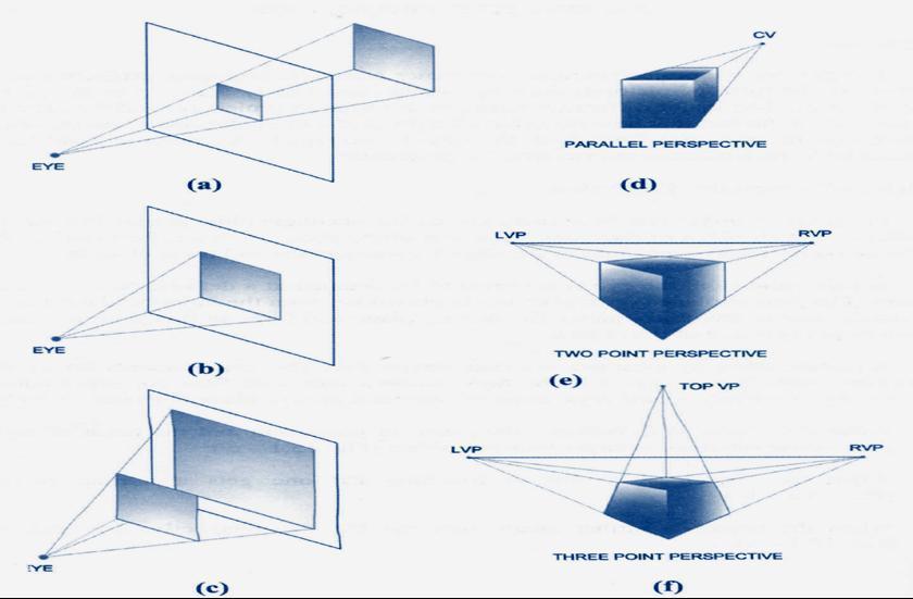
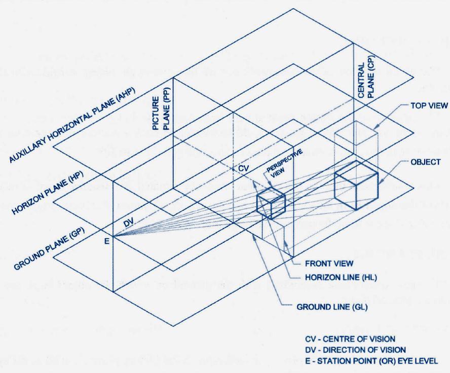
8 PERSPECTIVE PROJECTION


9 1) A point P is 20 mm behind PP and 30 mm above GP. The central plane is 25 mm to the left of the point. The station point is 30 mm infront of PP and 45 mm above GP. Draw the perspective view of the point.

10 2) A straight line PQ measures 40 mm is parallel to and 15 mm above GP and inclined at 30ᵒ to PP with an end 20 mm behind PP. The station point is 30 mm above the ground plane and 35 mm infront of PP and lies in a central plane that passes through the midpoint of PQ. Draw the perspective view.

11 3) A circle of diameter 30 mm lies on the ground plane with its center 25 mm behind the picture plane. Draw its perspective view as seen from a station 45 mm in front of the PP, 30 mm above the ground and 40mm to the left of the centre of the circle.

12 4. A square plane of side 30 mm is resting on ground plane with a corner of the plane touching the picture plane. One side of the plane inclined at an angle 50 o to PP. Station point is 50 m infront of PP and 50 mm above GP and 30 mm to the right of the resting corner. Draw the perspective projection of te plane by visual ray method.

13 5) A cube of side 30 mm is resting on the ground on one of its faces, with a vertical face in PP. and the rest behind it. The central plane is located 50 mm to the left of the center of the cube. The station point is 30 mm infront of PP and 50 mm above GP. Draw the perspective view of the solid.

14 6) A square pyramid of side of base 30 mm and altitude 60 mm stands on the ground vertically with an edge of base parallel to and is 15mm behind PP. The station point is 35 mm infront of PP and 60mm above the ground. The central plane is located 35 mm to the left of the axis of the solid. Draw the perspective projection.

15 7).A square prism of side 50 mm and height 80 mm is resting on ground plane with one of its ends. One of its rectangular faces is parallel to PP and 15 mm behind it. The station point is 25 mm to the right of the rectangular face on right. Station point is 40 mm infront of PP and 60 mm above GP. Draw the perspective projection by visual ray method

16 8) A cone of base diameter 50 mm and altitude 80 mm rests on ground plane with its axis 30 mm behind PP. Station point is 40 mm infront of PP, 70 mm above GP. The axis of the cone is 52 mm to the left of station point. Draw the perspective projection by visual ray method.

17 9) A pentagonal pyramid of 25 mm base side and axis height 50 mm is standing on its base on the ground plane with a base parallel to and 30 mm behind PP. The cental plane is 30 mm to the left of the apex and the station point is 50 mm infront of PP and 40 mm above the ground plane. Draw the perspective view of the pyramid.
ENGINEERING GRAPHICS UNIT V ISOMETRIC PROJECTION PERSPECTIVE PROJECTION
 ENGINEERING GRAPHICS UNIT V ISOMETRIC PROJECTION PERSPECTIVE PROJECTION 1.PICTORIAL PROJECTIONS To visualize the shape of the whole object in its 3- D form, all the two or three orthographic views of the
ENGINEERING DRAWING. UNIT III - Part A
 DEVELOPMENT OF SURFACES: ENGINEERING DRAWING UNIT III - Part A 1. What is meant by development of surfaces? 2. Development of surfaces of an object is also known as flat pattern of the object. (True/ False)
APJ ABDUL KALAM TECHNOLOGICAL UNIVERSITY SECOND SEMESTER B.TECH DEGREE EXAMINATION, MAY PART A Answer ANY Two questions. 10 marks each.
 B B2B111 Pages: 2 Reg. No. Name: SECOND SEMESTER B.TECH DEGREE EXAMINATION, MAY 2017 Max.Marks:50 Course Code: BE110 Duration:3Hours Answer ANY Two questions. 10 marks each. 1. A line AB 100 mm long and
GE 6152 ENGINEERING GRAPHICS
 GE 6152 ENGINEERING GRAPHICS UNIT - 4 DEVELOPMENT OF SURFACES Development of lateral surfaces of simple and truncated solids prisms, pyramids, cylinders and cones - Development of lateral surfaces of solids
4. Draw the development of the lateral surface of the part P of the cylinder whose front view is shown in figure 4. All dimensions are in cm.
 Code No: Z0122 / R07 Set No. 1 I B.Tech - Regular Examinations, June 2009 ENGINEERING GRAPHICS ( Common to Civil Engineering, Mechanical Engineering, Chemical Engineering, Bio-Medical Engineering, Mechatronics,
SAMPLE QUESTION PAPER III ENGINEERING GRAPHICS (046) Time Allowed: 3 hours Maximum Marks: 70
 Time Allowed: 3 hours Maximum Marks: 70") SAMPLE QUESTION PAPER III ENGINEERING GRAPHICS (046) Time Allowed: 3 hours Maximum Marks: 70 Note: (i) Attempt all the questions. (ii) Use both sides of the drawing sheet, if necessary. (iii) All dimensions
SAMPLE QUESTION PAPER III ENGINEERING GRAPHICS (046) Time Allowed: 3 hours Maximum Marks: 70 Note: (i) Attempt all the questions. (ii) Use both sides of the drawing sheet, if necessary. (iii) All dimensions
INSTITUTE OF AERONAUTICAL ENGINEERING
 Course Name Course Code Class Branch INSTITUTE OF AERONAUTICAL ENGINEERING Dundigal, Hyderabad - 500 043 MECHANICAL ENGINEERING TUTORIAL QUESTION BANK : ENGINEERING DRAWING : A10301 : I - B. Tech : Common
6. Draw the isometric view of a cone 40 mm diameter and axis 55 mm long when its axis is horizontal. Draw isometric scale. [16]
![6. Draw the isometric view of a cone 40 mm diameter and axis 55 mm long when its axis is horizontal. Draw isometric scale. [16]](/thumbs/85/92603403.jpg "6. Draw the isometric view of a cone 40 mm diameter and axis 55 mm long when its axis is horizontal. Draw isometric scale. [16]") Code No: R05010107 Set No. 1 I B.Tech Supplimentary Examinations, Aug/Sep 2007 ENGINEERING GRAPHICS ( Common to Civil Engineering, Mechanical Engineering, Mechatronics, Metallurgy & Material Technology,
Code No: R05010107 Set No. 1 I B.Tech Supplimentary Examinations, Aug/Sep 2007 ENGINEERING GRAPHICS ( Common to Civil Engineering, Mechanical Engineering, Mechatronics, Metallurgy & Material Technology,
I B.TECH- I SEMESTER DEPARTMENT OF MECHANICAL ENGINEERING ENGINEERING DRAWING
 I B.TECH- I SEMESTER DEPARTMENT OF MECHANICAL ENGINEERING ENGINEERING DRAWING ENGINEERING DRAWING UNIT-V DEFINITIONS: Axonometric Trimetric Dimetric Isometric It is a parallel technique used to create
Set No - 1 I B. Tech I Semester Regular/Supplementary Examinations Jan./Feb ENGINEERING DRAWING (EEE)
") Set No - 1 I B. Tech I Semester Regular/Supplementary Examinations Jan./Feb. - 2015 ENGINEERING DRAWING Time: 3 hours (EEE) Question Paper Consists of Part-A and Part-B Answering the question in Part-A
Set No - 1 I B. Tech I Semester Regular/Supplementary Examinations Jan./Feb. - 2015 ENGINEERING DRAWING Time: 3 hours (EEE) Question Paper Consists of Part-A and Part-B Answering the question in Part-A
E GRAPHICS ISOMETRIC PROJECTIONS S.RAMANATHAN ASST PROF MVSREC PH: CONCEPTS.
 E GRPHIS ISOMETRI PROJETIONS S.RMNTHN SST PROF MVSRE ONEPTS. Isometric projections are 3-D representation of objects. Since we deal mostly with solids which are 3-D objects, we use isometric projections
Change of position method:-
 Projections of Planes PROJECTIONS OF PLANES A plane is a two dimensional object having length and breadth only. Thickness is negligible. Types of planes 1. Perpendicular plane which have their surface
SIDDHARTH GROUP OF INSTITUTIONS :: PUTTUR
 SIDDHARTH GROUP OF INSTITUTIONS :: PUTTUR Siddharth Nagar, Narayanavanam Road 517583 QUESTION BANK Subject Code : Engineering Graphics& Design Course & Branch : B.Tech ALL Year & Sem : I B.Tech & I Sem
ENGINEERING GRAPHICS 1E9
 Lecture 3 Monday, 15 December 2014 1 ENGINEERING GRAPHICS 1E9 Lecture 3: Isometric Projections Lecture 3 Monday, 15 December 2014 2 What is ISOMETRIC? It is a method of producing pictorial view of an object
ENGINEERING GRAPHICS
 ENGINEERING GRAPHICS Course Structure Units Topics Marks Unit I Plane Geometry 16 1 Lines, angles and rectilinear figures 2 Circles and tangents 3 Special curves: ellipse, parabola, involute, cycloid.
ENGINEERING GRAPHICS
 ENGINEERING GRAPHICS CLASS - XII (046) DESIGN OF THE QUESTION PAPER Time : 3 Hrs Max. Marks : 70 The weightage of the distribution of marks over different contents of the question paper shall be as follows:
Second Semester Session Shri Ramdeobaba College of Engineering & Management, Nagpur. Department of Mechanical Engineering
 Second Semester Session- 2017-18 Shri Ramdeobaba College of Engineering & Management, Nagpur. Department of Mechanical Engineering Engineering Drawing Practical Problem Sheet Sheet No.:- 1. Scales and
ISOMETRIC PROJECTION. Contents. Isometric Scale. Construction of Isometric Scale. Methods to draw isometric projections/isometric views
 ISOMETRIC PROJECTION Contents Introduction Principle of Isometric Projection Isometric Scale Construction of Isometric Scale Isometric View (Isometric Drawings) Methods to draw isometric projections/isometric
Chapter 5 SECTIONS OF SOLIDS 5.1 INTRODUCTION
 Chapter 5 SECTIONS OF SOLIDS 5.1 INTRODUCTION We have studied about the orthographic projections in which a 3 dimensional object is detailed in 2-dimension. These objects are simple. In engineering most
BOARD DIPLOMA EXAMINATION, (C 14) APRIL/MAY 2015 DECE FIRST YEAR EXAMINATION ENGINEERING DRAWING
 APRIL/MAY 2015 DECE FIRST YEAR EXAMINATION ENGINEERING DRAWING") C 14 CHPC/EC/PET 107 4037 BOARD DIPLOMA EXAMINATION, (C 14) APRIL/MAY 2015 DECE FIRST YEAR EXAMINATION ENGINEERING DRAWING Time : 3 hours ] [ Total Marks : 60 Instructions : (1) Answer all questions. PART
C 14 CHPC/EC/PET 107 4037 BOARD DIPLOMA EXAMINATION, (C 14) APRIL/MAY 2015 DECE FIRST YEAR EXAMINATION ENGINEERING DRAWING Time : 3 hours ] [ Total Marks : 60 Instructions : (1) Answer all questions. PART
SAMPLE QUESTION PAPER II ENGINEERING GRAPHICS (046)
") SAMPLE QUESTION PAPER II ENGINEERING GRAPHICS (046) Time Allowed: 3 hours Maximum Marks: 70 Note: (i) Attempt all the questions. (ii) Use both sides of the drawing sheet, if necessary. (iii) All dimensions
SAMPLE QUESTION PAPER II ENGINEERING GRAPHICS (046) Time Allowed: 3 hours Maximum Marks: 70 Note: (i) Attempt all the questions. (ii) Use both sides of the drawing sheet, if necessary. (iii) All dimensions
ENGINEERING DRAWING I
 INSTITUTE OF ENGINEERING DEPARTMENT OF MECHANICAL ENGINEERING ENGINEERING DRAWING I [TUTORIAL SHEETS] 1 CONTENTS Sheet No. 1: Technical Lettering 3 Sheet No. 2: Plane Geometrical Construction 5 Sheet No.
GE ENGINEERING GRAPHICS
 ANNA UNIVERSITY, CHENNAI (REGULATION GE8152 - ENGINEERING GRAPHICS B.E SEMESTER I Lecture Tutorial Practical Marks Credits Total Hours 2 0 3 100 4 90 Mr.S.Gokul (Asst. Prof/Mech) Sri Eshwar College of
BHARATHIDASAN ENGINEERING COLLEGE MGR NAGAR, NATRAM PALLI. Department of Mechanical Engineering GE6152 ENGINEERING GRAPHICS NOTES
 BHARATHIDASAN ENGINEERING COLLEGE MGR NAGAR, NATRAM PALLI Department of Mechanical Engineering GE6152 ENGINEERING GRAPHICS NOTES GE6152 ENGINEERING GRAPHICS OBJECTIVES: concepts, ideas and design of Engineering
Engineering Graphics. Practical Book. Government Engineering College Bhuj (Kutch - Gujarat) Department of Mechanical Engineering
 Department of Mechanical Engineering") Engineering Graphics Practical Book ASHISH J. MODI Department of Mechanical Engineering Government Engineering College Bhuj 370 001 (Kutch - Gujarat) SYLLABUS (AS PER GUJARAT TECHNOLOGICAL UNIVERSITY,
Engineering Graphics Practical Book ASHISH J. MODI Department of Mechanical Engineering Government Engineering College Bhuj 370 001 (Kutch - Gujarat) SYLLABUS (AS PER GUJARAT TECHNOLOGICAL UNIVERSITY,
1 ISOMETRIC PROJECTION SECTION I: INTRODUCTION TO ISOMETRIC PROJECTION
 1 ISOMETRIC PROJECTION SECTION I: INTRODUCTION TO ISOMETRIC PROJECTION Orthographic projection shows drawings of an object in a two-dimensional format, with views given in plan, elevation and end elevation
ENGINEERING DRAWING
 Subject Code: R13109/R13 Set No - 1 I B. Tech I Semester Regular/Supplementary Examinations Jan./Feb. - 2015 ENGINEERING DRAWING (Common to ECE, EIE, Bio-Tech, EComE, Agri.E) Time: 3 hours Max. Marks:
DELHI TECHNOLOGICAL UNIVERSITY ENGINEERING GRAPHICS LAB MANUAL
 DELHI TECHNOLOGICAL UNIVERSITY ENGINEERING GRAPHICS LAB MANUAL NAME: - ROLL NO: - GROUP: - BRANCH: - GROUP TEACHER: Page 1 www.rooplalrana.com 1 GENERAL INSTRUCTIONS FOR ENGG. GRAPHICS LAB 1) Students
Government of Karnataka Department of Technical Education Board of Technical Examinations, Bengaluru Course Title: ENGINEERING DRAWING-II
 Government of Karnataka Department of Technical Education Board of Technical Examinations, Bengaluru Course Title: ENGINEERING DRAWING-II Credits (L:T:P) : 0:2:4 Total Contact Hours: 78 Course Code: 15CE22D
Drawing sheet: - The various size of the drawing sheet used for engineering drawing as per IS Are listed in the table
 Dronacharya Group of Institutions, Greater Noida Computer Aided Engineering Graphics (CAEG) (NCE 151/251) List of Drawing Sheets: 1. Letter writing & Dimensioning. 2. Projection of Points & Lines. 3. Projection
Orthographic Projection
 Orthographic Projection Why Orthographic Projection is used in technical drawing Orthographic projection is a method of producing a number of separate two-dimensional inter-related views, which are mutually
GOVERNMENT POLYTECHNIC, VALSAD MECHANICAL ENGINEERING DEPARTMENT ASSIGNMENT SUB: MECHANICAL DRAFTING (C321901) TERM:172
 TERM:172") GOVERNMENT POLYTECHNIC, VALSAD MECHANICAL ENGINEERING DEPARTMENT ASSIGNMENT SUB: MECHANICAL DRAFTING (C321901) TERM:172 1) When all the dimension are placed above the dimension line, it is called (a) Aligned
GOVERNMENT POLYTECHNIC, VALSAD MECHANICAL ENGINEERING DEPARTMENT ASSIGNMENT SUB: MECHANICAL DRAFTING (C321901) TERM:172 1) When all the dimension are placed above the dimension line, it is called (a) Aligned
BVRIT HYDERABAD College of Engineering for Women Department of Basic Sciences and Humanities
 BVRIT HYDERABAD College of Engineering for Women Department of Basic Sciences and Humanities Hand Out Subject Name: Engineering Graphics Prepared by (Faculty(s) Name): Mr. M Gopikrishna, Asst.Professor,
Chapter 4 ORTHOGRAPHIC PROJECTION
 Chapter 4 ORTHOGRAPHIC PROJECTION 4.1 INTRODUCTION We, the human beings are gifted with power to think. The thoughts are to be shared. You will appreciate that different ways and means are available to
ENGINEERING DRAWING. 1. Set squares are used to draw different angles. What is the angel a formed by the 45⁰ set square? Give a brief answer.
 ENGINEERING DRAWING 1. Set squares are used to draw different angles. What is the angel a formed by the 45⁰ set square? Give a brief answer. 2. Which is the correct method of hatching a plane surface?
B.E. 1 st Year Engineering Graphics ( )
") B.E. 1 st Year Engineering Graphics (2110013) Department of Mechanical Engineering Darshan Institute of Engg. & Tech., Rajkot Darshan Institute Of Engg. & Technology List Of Instruments SR NO. 1. Set-Square
B.E. 1 st Year Engineering Graphics (2110013) Department of Mechanical Engineering Darshan Institute of Engg. & Tech., Rajkot Darshan Institute Of Engg. & Technology List Of Instruments SR NO. 1. Set-Square
ORTHOGRAPHIC PROJECTION
 ORTHOGRAPHIC PROJECTION INTRODUCTION Any object has three dimensions, that is, length, width and thickness. A projection is defined as a representation of an object on a two dimensional plane. The projections
ENGINEERING GRAPHICS
 ENGINEERING GRAPHICS Course Structure Parts/Units Topics Marks Unit - I Isometric Projection of Solids 25 Machine Drawing 45 Part A. Drawing of Machine Parts Unit - II Part B. Assembly Drawing and Dis-assembly
Trade of Metal Fabrication. Module 6: Fabrication Drawing Unit 13: Parallel Line Development Phase 2
 Trade of Metal Fabrication Module 6: Fabrication Drawing Unit 13: Parallel Line Development Phase 2 Table of Contents List of Figures... 4 List of Tables... 5 Document Release History... 6 Module 6 Fabrication
TPCT s College of Engineering, Osmanabad. Laboratory Manual. Engineering Graphics. For. First Year Students. Manual Prepared by B. G.
 TPCT s College of Engineering, Osmanabad Laboratory Manual Engineering Graphics For First Year Students Manual Prepared by B. G. Kadam Author COE, Osmanabad TPCT s College of Engineering Solapur Road,
Downloaded from ENGINEERING DRAWING. Time allowed : 3 hours Maximum Marks : 70
 ENGINEERING DRAWING Time allowed : 3 hours Maximum Marks : 70 Note : (i) (ii) Attempt all the questions. Use both sides of the drawing sheet, if necessary. (iii) All dimensions are in millimeters. (iv)
ENGINEERING DRAWING CLASS-XI THEORY
 CLASS-XI THEORY One Paper 3 Hours 7O Marks Unit Marks PLANE GEOMETRY 1. Construction of lines, angles and rectilner figures 4 2. Construction of circles, semi-circles and tangents 6 3. Construction of
ENGINEERING GRAPHICS (Code No. 046)
") ENGINEERING GRAPHICS (Code No. 046) CLASS XI-XII The subject of 'Engineering Graphics' has become an indispensable tool for Engineers, Technocrats, Architects, Draftsmen, Surveyors, Designers and many
ENGINEERING GRAPHICS (Code No. 046) CLASS XI-XII The subject of 'Engineering Graphics' has become an indispensable tool for Engineers, Technocrats, Architects, Draftsmen, Surveyors, Designers and many
Design & Communication Graphics
 L.84/85 Design & Communication Graphics Marking Scheme Ordinary Pg. 3 Higher Pg. 12 2013 L.84/85_MS 1/20 2013 L.84/85_MS 2/20 SECTION A - Core - Answer Any Three of the questions on this A3 sheet A-1.
ENGINEERING GRAPHICS (XI-XII) (Code No. 046)
 (Code No. 046)") ENGINEERING GRAPHICS (XI-XII) (Code No. 046) The subject of 'Engineering Graphics' has become an indispensable tool for Engineers, Technocrats, Architects, Draftsmen, Surveyors, Designers and many other
ENGINEERING GRAPHICS (XI-XII) (Code No. 046) The subject of 'Engineering Graphics' has become an indispensable tool for Engineers, Technocrats, Architects, Draftsmen, Surveyors, Designers and many other
Solutions to Exercise problems
 Brief Overview on Projections of Planes: Solutions to Exercise problems By now, all of us must be aware that a plane is any D figure having an enclosed surface area. In our subject point of view, any closed
Multi-View Drawing Review
 Multi-View Drawing Review Sacramento City College EDT 300/ENGR 306 EDT 300 / ENGR 306 - Chapter 5 1 Objectives Identify and select the various views of an object. Determine the number of views needed to
COMPUTER AIDED ENGINEERING DRAWING
 COMPUTER AIDED ENGINEERING DRAWING [As per Choice Based Credit System (CBCS) scheme] (Effective from the academic year 2017-2018) SEMESTER - I/II Subject Code 17CED14/17CED24 IA Marks 40 Number of Lecture
ENGINEERING GRAPHICS CLASS - XII (046) DESIGN OF THE QUESTION PAPER
 DESIGN OF THE QUESTION PAPER") ENGINEERING GRAPHICS CLASS - XII (046) DESIGN OF THE QUESTION PAPER Time : 3 Hrs Max. Marks : 70 The weightage of the distribution of marks over different contents of the question paper shall be as follows:
ENGINEERING GRAPHICS CLASS - XII (046) DESIGN OF THE QUESTION PAPER Time : 3 Hrs Max. Marks : 70 The weightage of the distribution of marks over different contents of the question paper shall be as follows:
Orthographic Projection 1
 Orthographic Projection 1 What Is Orthographic Projection? Basically it is a way a representing a 3D object on a piece of paper. This means we make the object becomes 2D. The difference between Orthographic
Lesson 4: General Pyramids and Cones and Their Cross-Sections
 : General Pyramids and Cones and Their Cross-Sections Learning Target 1. I can state the definition of a general pyramid and cone, and that their respective cross-sections are similar to the base. 2. I
ORTHOGRAPHIC PROJECTION
 ORTHOGRAPHIC PROJECTION C H A P T E R S I X OBJECTIVES 1. Recognize and the symbol for third-angle projection. 2. List the six principal views of projection. 3. Understand which views show depth in a drawing
ENGINEERING DRAWING LECTURE 4
 ENGINEERING DRAWING LECTURE 4 Conventions Convention or Code: The representation of any matter by some sign or mark on the drawing is known as convention or code. The convention make the drawing simple
Cross Sections of Three-Dimensional Figures
 Domain 4 Lesson 22 Cross Sections of Three-Dimensional Figures Common Core Standard: 7.G.3 Getting the Idea A three-dimensional figure (also called a solid figure) has length, width, and height. It is
Performance Task: In the image below, there are three points (J, K, and I) located on different edges of a cube.
 located on different edges of a cube.") Cube Cross Sections Performance Task: In the image below, there are three points (J, K, and I) located on different edges of a cube. points I, K, and J. This plane would create a cross section through
Cube Cross Sections Performance Task: In the image below, there are three points (J, K, and I) located on different edges of a cube. points I, K, and J. This plane would create a cross section through
NOTE: Topic No. 1, 8 and 9 of the above syllabus to be covered in Practical Hours.
 Subject Engineering Graphics Teaching scheme Theory Tutorial Practical Credits 2 0 4 6 Engineering Graphics syllabus 1. Introduction to Engineering Graphics, Drawing instruments and accessories, BIS SP
ORDINARY LEVEL PAST PAPERS
 ORDINARY LEVEL PAST PAPERS UNEB S4 1982 SECTION I PLANE GEOMETRY 1. (a) Construct a diagonal scale of 40mm to 10mm to read up to 20mm by 0.02mm. (b) Indicate on your scale the following readings. (i) 14.8mm.
(Common to E&E /MECHATRONICS/ HPT/ WSM/TEXTILE /MINING/CERAMICS/AGRICULTURE ENGG./ AERONAUTICAL ENGG./LEATHER & FASHION TECHNOLOGY Programmes)
") Government of Karnataka Department of Technical Education Board of Technical Examinations, Bengaluru Course Title: ENGINEERING Course Code: 15ME01D DRAWING Semester : I / II Core/ Elective: Core Teaching
Government of Karnataka Department of Technical Education Board of Technical Examinations, Bengaluru Course Title: ENGINEERING Course Code: 15ME01D DRAWING Semester : I / II Core/ Elective: Core Teaching
 6.1 INTRODUCTION Chapter 6 ORTHOGRAPHIC PROJECTIONS OF SIMPLE MACHINE BLOCKS We have already made you aware of many simple geometrical shapes (laminae), projected on such planes (vertical plane, horizontal
technical drawing
 technical drawing school of art, design and architecture nust spring 2011 http://www.youtube.com/watch?v=q6mk9hpxwvo http://www.youtube.com/watch?v=bnu2gb7w4qs Objective abstraction - axonometric view
Whirlygigs for Sale! Rotating Two-Dimensional Figures through Space. LESSON 4.1 Skills Practice. Vocabulary. Problem Set
 LESSON.1 Skills Practice Name Date Whirlygigs for Sale! Rotating Two-Dimensional Figures through Space Vocabulary Describe the term in your own words. 1. disc Problem Set Write the name of the solid figure
Copyrighted Material. Copyrighted Material. Copyrighted. Copyrighted. Material
 Engineering Graphics ORTHOGRAPHIC PROJECTION People who work with drawings develop the ability to look at lines on paper or on a computer screen and "see" the shapes of the objects the lines represent.
2. Line composed of closely and evenly spaced short dashes in a drawing represents
 1. Hidden lines are drawn as (a) dashed narrow lines (b) dashed wide lines (c) long-dashed dotted wide line (d) long-dashed double dotted wide line Ans: (a) 2. Line composed of closely and evenly spaced
11/12/2015 CHAPTER 7. Axonometric Drawings (cont.) Axonometric Drawings (cont.) Isometric Projections (cont.) 1) Axonometric Drawings
 Axonometric Drawings (cont.) Isometric Projections (cont.) 1) Axonometric Drawings") CHAPTER 7 1) Axonometric Drawings 1) Introduction Isometric & Oblique Projection Axonometric projection is a parallel projection technique used to create a pictorial drawing of an object by rotating the
CHAPTER 7 1) Axonometric Drawings 1) Introduction Isometric & Oblique Projection Axonometric projection is a parallel projection technique used to create a pictorial drawing of an object by rotating the
Technical Drawing Paper 1 - Higher Level (Plane and Solid Geometry)
") Coimisiún na Scrúduithe Stáit State Examinations Commission 2008. M81 Leaving Certificate Examination 2008 Technical Drawing Paper 1 - Higher Level (Plane and Solid Geometry) (200 Marks) Friday 13 June
Coimisiún na Scrúduithe Stáit State Examinations Commission 2008. M81 Leaving Certificate Examination 2008 Technical Drawing Paper 1 - Higher Level (Plane and Solid Geometry) (200 Marks) Friday 13 June
DEPARTMENT OF MECHANICAL ENGINEERING, IIT DELHI
 MEL 110 LABORATORY 1 (to be done in CAGI Lab. Room: III 331) DURATION: 3 Hrs 50 Min. Note: Missing dimensions may be suitably assumed. Exercise 1: Visualize orthographic and isometric views of 3D models/objects:
WORI(F'ORCE. P.O. BOX 2707 Kigala, Rwanda Tel: (+250)
") F MVM - Technical Drawing and D.C.G T125 Thursday, 19lll /2015 08:30-11:30 WORI(F'ORCE ffi DE\'ELOPMENT AUTHORITY P.O. BOX 2707 Kigala, Rwanda Tel: (+250) 255113365 ADVANCED LEVEL NATIONAL EXAMINATIONS,
F MVM - Technical Drawing and D.C.G T125 Thursday, 19lll /2015 08:30-11:30 WORI(F'ORCE ffi DE\'ELOPMENT AUTHORITY P.O. BOX 2707 Kigala, Rwanda Tel: (+250) 255113365 ADVANCED LEVEL NATIONAL EXAMINATIONS,
Multiview Drawing. Definition: Graphical representation of a 3- dimensional object on one plane (sheet of paper) using two or more views.
 using two or more views.") Multiview Drawing Definition: Graphical representation of a 3- dimensional object on one plane (sheet of paper) using two or more views. Multiview Drawing Another name for multiview drawing is orthographic
Multiview Drawing Definition: Graphical representation of a 3- dimensional object on one plane (sheet of paper) using two or more views. Multiview Drawing Another name for multiview drawing is orthographic
ENGINEERING DRAWING SKKK 1021 ISOMETRIC DRAWING. Agus Arsad, Azizul Azri Bin Mustaffa 10/2/2012 1
 ENGINEERING DRAWING SKKK 1021 ISOMETRIC DRAWING Agus Arsad, Azizul Azri Bin Mustaffa 10/2/2012 1 LEARNING OUTCOMES ISOMETRIC DRAWING It is expected that students will be able to: Understand the significance
DESIGN & COMMUNICATION GRAPHICS
 photograph of three balls is shown. ll three are in mutual contact and rest on the horizontal plane. The centres of the two larger ones lie in a line which is parallel to the vertical plane. The drawing
JUNIOR CERTIFICATE 2009 MARKING SCHEME TECHNICAL GRAPHICS HIGHER LEVEL
 . JUNIOR CERTIFICATE 2009 MARKING SCHEME TECHNICAL GRAPHICS HIGHER LEVEL Sections A and B Section A any ten questions from this section Q1 12 Four diagrams, 3 marks for each correct label. Q2 12 2 marks
Pictorial Drawings. DFTG-1305 Technical Drafting Prepared by Francis Ha, Instructor
 DFTG-1305 Technical Drafting Prepared by Francis Ha, Instructor Pictorial Drawings Geisecke s textbook for reference: 14 th Ed. Ch. 15: p. 601 Ch. 16: p. 620 15 th Ed. Ch. 14: p. 518 Ch. 15: p. 552 Update:
ENGINEERING GRAPHICS
 ENGINEERING GRAPHICS Time allowed : 3 hours Maximum Marks : 70 Note : (ii) Attempt all the questions. Use both sides of the drawing sheet, if necessary. (iii) All dimensions are in millimetres. (iv) Missing
(As per New Revised Syllabus of Anna University) Department of Mechanical Engineering. SATHYABAMA UNIVERSITY Jeppiaar Nagar, Chennai
 Department of Mechanical Engineering. SATHYABAMA UNIVERSITY Jeppiaar Nagar, Chennai") (1*,1((5,1* *5$3+,&6 (As per New Revised Syllabus of Anna University) Dr. S.RAMACHANDRAN, M.E., Ph.D. Professor & Head K. PANDIAN, M.E., E.V.V.RAMANAMURTHY, M.Tech., R. DEVARAJ, M.E., Associate Professors
(1*,1((5,1* *5$3+,&6 (As per New Revised Syllabus of Anna University) Dr. S.RAMACHANDRAN, M.E., Ph.D. Professor & Head K. PANDIAN, M.E., E.V.V.RAMANAMURTHY, M.Tech., R. DEVARAJ, M.E., Associate Professors
Surface Developments. Sacramento City College Engineering Design Technology. Surface Developments 1
 Surface Developments Sacramento City College Engineering Design Technology Surface Developments 1 Surface Developments A surface development is a full-size layout of an object made on a single flat plane.
Engineering Graphics& Design Scheme and Credits L T P Credits Major Test Minor Test Total Time
 Course code ES-109A Course title Engineering Graphics& Design Scheme and Credits L T P Credits Major Test Minor Test Total Time 1 2 0 3 75 25 100 3h Course Outcomes Objective To expose students to the
Technical Graphics Higher Level
 Coimisiún na Scrúduithe Stáit State Examinations Commission Junior Certificate Examination 2005 Technical Graphics Higher Level Marking Scheme Sections A and B Section A Q1. 12 Four diagrams, 3 marks for
Shapes and Patterns. Lesson 1 Exploring Plane Shapes (Part 1) Name the shapes. triangle circle rectangle square Color the squares.
 Name the shapes. triangle circle rectangle square Color the squares.") CHAPTER 5 Shapes and Patterns Lesson 1 Exploring Plane Shapes (Part 1) Name the shapes. triangle circle rectangle square 1. 2. 3. 4. Color the squares. 5. Extra Practice 1A 71 Color the shapes that are
CHAPTER 5 Shapes and Patterns Lesson 1 Exploring Plane Shapes (Part 1) Name the shapes. triangle circle rectangle square 1. 2. 3. 4. Color the squares. 5. Extra Practice 1A 71 Color the shapes that are
DMT113 Engineering Drawing. Chapter 3 Stretch System
 DMT113 Engineering Drawing Chapter 3 Stretch System Contents Theory & Multiview Planes 6 Principle Views Multiview Sketching Technique & Perspective First & Third Angle Multiview Representations Theory
Multiviews and Auxiliary Views
 Multiviews and Auxiliary Views Multiviews and Auxiliary Views Objectives Explain orthographic and multiview projection. Identifying the six principal views. Apply standard line practices to multiviews
Understand Plane Sections of Prisms and Pyramids
 Lesson 25 Understand Plane Sections of Prisms and Pyramids Name: Prerequisite: How do you identify shapes according to their properties? Study the example showing how to identify shapes by using their
Isometric Drawing Chapter 26
 Isometric Drawing Chapter 26 Sacramento City College EDT 310 EDT 310 - Chapter 26 - Isometric Drawing 1 Drawing Types Pictorial Drawing types: Perspective Orthographic Isometric Oblique Pictorial - like
Name: Class: Date: Complete each sentence with one of the following names of the geometric solids. cylinder rectangular prism cone pyrmaid
 1. Use pencil and paper to answer the question. Complete each sentence with one of the following names of the geometric solids. cylinder rectangular prism cone pyrmaid a. I have a square base and I have
Downloaded from
 Symmetry 1 1.Find the next figure None of these 2.Find the next figure 3.Regular pentagon has line of symmetry. 4.Equlilateral triangle has.. lines of symmetry. 5.Regular hexagon has.. lines of symmetry.
Auxiliary Elevations and Plans
 Chapter 18 uxiliary Elevations and Plans uxiliary Elevations The pictorial view of the thatched cottage shown below indicates how the front elevation is: (i) Obtained from a viewing direction looking in
PESIT-BSC Department of Science & Humanities
 LESSON PLAN 15CED14/24 COMPUTER AIDED ENGINEERING DRAWING Course objectives: The Engineering drawing is an important tool for all Engineers and for many others professionals. It is the language of Engineers.
Marking Scheme Engineering Graphics
 Marking Scheme Engineering Graphics All Questions are to be answered correctly and accurately. General Note: (i) (ii) (iii) (iv) (v) Marks are to be awarded in proportion to the work done. Mistakes in
ME 113 Computer Aided Engineering Drawing
 ME 113 Computer Aided Engineering Drawing Orthographic Projection - Visualizing Solids and Multiview Drawings Asst.Prof.Dr.Turgut AKYÜREK Çankaya University, Ankara Visualizing Solids and Multiview Drawings
UNIT I PLANE CURVES AND FREE HAND SKETCHING CONIC SECTIONS
 UNIT I PLANE CURVES AND FREE HAND SKETCHING CONIC SECTIONS Definition: The sections obtained by the intersection of a right circular cone by a cutting plane in different positions are called conic sections
Period: Date Lesson 2: Common 3-Dimensional Shapes and Their Cross- Sections
 : Common 3-Dimensional Shapes and Their Cross- Sections Learning Target: I can understand the definitions of a general prism and a cylinder and the distinction between a cross-section and a slice. Warm
Can You Cut It? Slicing Three-Dimensional Figures
 Name: Period: Can You Cut It? Slicing Three-Dimensional Figures Lesson Activity 1. The Cube Using modeling clay or play-doh, each student creates a model of a cube. With your group, predict the type of
CHAPTER 01 PRESENTATION OF TECHNICAL DRAWING. Prepared by: Sio Sreymean
 CHAPTER 01 PRESENTATION OF TECHNICAL DRAWING Prepared by: Sio Sreymean 2015-2016 Why do we need to study this subject? Effectiveness of Graphics Language 1. Try to write a description of this object. 2.
Key Stage 3 Mathematics. Common entrance revision
 Key Stage 3 Mathematics Key Facts Common entrance revision Number and Algebra Solve the equation x³ + x = 20 Using trial and improvement and give your answer to the nearest tenth Guess Check Too Big/Too
CLASS views from detail on a grid paper. (use appropriate line types to show features) - Optional views. Turn in for grading on class 6 (06/04)
 - Optional views. Turn in for grading on class 6 (06/04)") CLASS 4 Review: - Projections - Orthographic projections Lab: - 3 views from detail on a grid paper. (use appropriate line types to show features) - Optional views. Turn in for grading on class 6 (06/04)
CLASS 4 Review: - Projections - Orthographic projections Lab: - 3 views from detail on a grid paper. (use appropriate line types to show features) - Optional views. Turn in for grading on class 6 (06/04)
Volume and Surface Area (H) Intervention Booklet
 Intervention Booklet") Volume and Surface Area (H) Intervention Booklet Prisms (Including Cylinders) Things to remember: Volume of a prism = area of cross section x vertical height Area of triangle = b x h Area of circle = π
Volume and Surface Area (H) Intervention Booklet Prisms (Including Cylinders) Things to remember: Volume of a prism = area of cross section x vertical height Area of triangle = b x h Area of circle = π
Civil Engineering Drawing
 Civil Engineering Drawing Third Angle Projection In third angle projection, front view is always drawn at the bottom, top view just above the front view, and end view, is drawn on that side of the front
UNIT 5a STANDARD ORTHOGRAPHIC VIEW DRAWINGS
 UNIT 5a STANDARD ORTHOGRAPHIC VIEW DRAWINGS 5.1 Introduction Orthographic views are 2D images of a 3D object obtained by viewing it from different orthogonal directions. Six principal views are possible
ENGR 1182 Exam 1 First Mid Term Exam Study Guide and Practice Problems
 Spring Semester 2016 ENGR 1182 Exam 1 First Mid Term Exam Study Guide and Practice Problems Disclaimer Problems in this study guide resemble problems relating mainly to the pertinent homework assignments.
ENGINEERING DRAWING N1
 REQUIREMENTS: A2 drawing paper T590(E)(M24)T NATIONAL CERTIFICATE ENGINEERING DRAWING N1 (8090261) 24 March 2017 (X-Paper) 09:00 13:00 Drawing instruments and calculators may be used. This question paper
June 2016 Regents GEOMETRY COMMON CORE
 1 A student has a rectangular postcard that he folds in half lengthwise. Next, he rotates it continuously about the folded edge. Which three-dimensional object below is generated by this rotation? 4) 2