ENGINEERING DRAWING LECTURE 4
|
|
|
- Leo Oliver
- 6 years ago
- Views:
Transcription

1 ENGINEERING DRAWING LECTURE 4
2 Conventions Convention or Code: The representation of any matter by some sign or mark on the drawing is known as convention or code. The convention make the drawing simple and easy to draw.
3 Convention for Lines Since, engineering drawing is the systematic combination of different types of lines, it is therefore, essential for the students to have clearly in mind the difference between the various types of lines.
4 Detailed Description and Uses of Various Lines 1. Visible Outline or Object Line: The outline or object line is represented by thick line and used to show the outer visible feature of the object in the drawing. Every edge or surface that is visible is represented by these lines. 2. Section Line or Hatching Line: It is a thin continuous line and is used for the purpose of sectioning an object. (Note: The section lines are drawn at angle of 45 to the horizontal line and are spaced uniformly from 2 to 4 mm apart depending upon the size of the object)
5 3. Centre Line, Locus Line, Pitch Circles, Extreme Position of Moveable Parts and Parts Situated Infront of Cutting Plane: These lines are represented by long and short dashes in proportion ranging from 6:1 to 4:1, closely and evenly spaced in any drawing. The Proportional once selected should be maintained through the drawing these are used to show the centre and location of cylindrical, conical and spherical object. The following rules should be kept in mind while drawing centre lines of various objects:- i. The centre lines should not end at out line representing surfaces but should extend approximately from 2 to 5 mm beyond the out lines of the object ii. Where centre lines cross, the short dashes should ntersect at symmetrical. In case of very small circles, the short dashes should be neglected while drawing centre lines.
6 4. Hidden Line: The hidden line is represented by short dashes, closely and evenly spaced. It is used to show the invisible for hidden parts on the drawing. 5. Construction Line: It is a thin continuous line and is used for constructing an object. These Lines do not appear in finished drawing except in geometrical drawing. 6. Dimension Line: It is thin continuous line, for giving dimension. This line terminates arrow heads where the dimension lines meet the extension lines. 7. Extension Line: It is a thin continuous line used for dimensioning an object. 8. Projectors Line: It is a thin continuation of outlines and is used for drawing projector.
7 9. Cutting Plane Line: The cutting plane line is represented by thick long line at the ends with thin long and short lines at the centre. It is used to show the edge of the cutting plane. 10. Short Break Line: The short break line is represented by thin free-hand and is used to show the break of an object for a short length. It results in a saving in space and time used for drawing without loss of any details. 11. Long Break Line: The long line is represented by thin ruled line provided with free-hand zig-zags at suitable intervals and is used to show the break for a considerable length of the object.
8
9
10 Conventions For Various Materials In engineering practice, there are different types of materials used for manufacturing the various parts of a machine. It is therefore, desirable that different conventions should be adopted to differentiate various materials for convenience on the drawing. The conventions materials thus save time and labour of the drawing work.
11
12 Dimensioning The art of writing the various sizes or measurements on the finished drawing of an object is known as dimensioning.
13 Notation of Dimensioning The notation of dimensioning consists of dimension lines, extension lines, arrow heads, dimension figures, notes, symbols, etc. These notations are explained below:- 1. Dimension Line: Dimension line is a thin continuous line used to indicate the measurement which is shown by figure in a space above the dimension line or space left in the dimension line. 2. Extension Line: Extension line is also a thin continuous line extending beyond the outline of the object. It should extend about 3 mm beyond the dimension line. There should be a visible gap of 1.5 mm between the feature s corners and the end of the extension line.
14 3. Arrow Heads: Arrow heads are used to terminate dimension lines. These touch the extension lines and indicates the extent of a dimension. The length of the arrow-head is about three times its width, the space in the arrow-heads should be filled in. The size of the arrow-heads should be proportionate to the thickness of the lines of the drawing. 4. Dimension Figure: A numerical that indicates the size of a particular feature of an object is called dimension figure. 5. Leader (Pointer Line): A leader is a thin continuous line drawn from note of the figure to show where it applies. It is terminated by an arrow-head or a dot. The arrow-head touches the outline, whereas the dot is placed within the outline of the object. The leader is generally drawn at any convenient angle, usually 30, 45 and 60 but of not less than 30. (Note: The use of long leaders should be avoided even if it is involves repetition dimensions or notes)

15 6. Notes: A note on drawing gives complete information regarding specific operation relating to a feature. It is generally placed outside a view and read in such a way that the drawing is viewed from the bottom edge. 7. Symbol: A symbol is the representation of any object by some mark on the drawing. It is used to save time and labour of drawing work.

16 Spacing of Dimensions
17 Theory of Dimensioning An object may be considered to be made up of a number of geometrical shapes such as prism, cylinder, pyramid, cone, sphere, etc. It then becomes very simple to dimension these geometric forms in a manner that will show their individual sizes and location to each other. Thus, the following two types of dimensions are commonly used in engineering drawing: 1. Size Dimensions. 2. Location Dimensions.
18 Types of Dimensions Size Dimensions: The dimensions which indicate the various sizes of the object such as length, breadth, diameter, etc. are known as size dimensions. Location Dimensions: The dimensions which locate the position of one feature with respect to the other feature are known as location dimensions. Distances between the centre lines of the holes from the edges of features are given by location dimensions.
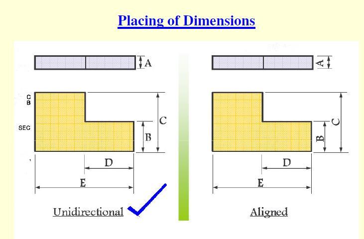
19 System of Placing Dimensions Aligned System: In this system, all dimensions are so placed that they may be read from the bottom or the right hand edges of the drawing sheet. Here all the dimensions are placed normal and above the dimensions lines (Latest Method). Unidirectional System: In this system, all dimensions are so placed that they may be read from bottom edge of the drawing sheet. Note, there is no restriction on the controlling the direction of the dimension lines.
20
21
22
23
24
25
26
27
28 Unit of Dimensioning As far s possible, all dimensions should be given preferably in one unit only, i.e in millimeters. The symbol of unit mm can therefore be omitted while writing each dimensions but a note is added in a prominent place near the tittle block that All dimensions are in millimeters.
29 Exercise
Chapter 2: Dimensioning Basic Topics Advanced Topics Exercises
 Chapter 2: Dimensioning Basic Topics Advanced Topics Exercises Dimensioning: Basic Topics Summary 2-1) Detailed Drawings 2-2) Learning to Dimension 2-3) Dimension Appearance and Techniques. 2-4) Dimensioning
Drawing sheet: - The various size of the drawing sheet used for engineering drawing as per IS Are listed in the table
 Dronacharya Group of Institutions, Greater Noida Computer Aided Engineering Graphics (CAEG) (NCE 151/251) List of Drawing Sheets: 1. Letter writing & Dimensioning. 2. Projection of Points & Lines. 3. Projection
UNIT Lines and Symbols
 3 UNIT Lines and Symbols Various lines on a drawing have different meanings. They may appear solid, broken, thick, or thin. Each is designed to help the blueprint reader make an interpretation. The standards
ENGINEERING GRAPHICS ESSENTIALS. (A Text and Lecture Aid) Second Edition. Kirstie Plantenberg University of Detroit Mercy SDC PUBLICATIONS
 Second Edition. Kirstie Plantenberg University of Detroit Mercy SDC PUBLICATIONS") ENGINEERING GRAPHICS ESSENTIALS (A Text and Lecture Aid) Second Edition Kirstie Plantenberg University of Detroit Mercy SDC PUBLICATIONS Schroff Development Corporation www.schroff.com www.schroff-europe.com
ENGINEERING GRAPHICS ESSENTIALS (A Text and Lecture Aid) Second Edition Kirstie Plantenberg University of Detroit Mercy SDC PUBLICATIONS Schroff Development Corporation www.schroff.com www.schroff-europe.com
Multiview Projection
 DFTG-1305 Technical Drafting Prof. Francis Ha Session 4 Multiview Projection (or Orthographic Projection) Reading: Geisecke s textbook: 14 th Ed. Chapter 5 p.162 15 th Ed. Chapter 6 p.232 Update: 17-0510
(As per New Revised Syllabus of Anna University) Department of Mechanical Engineering. SATHYABAMA UNIVERSITY Jeppiaar Nagar, Chennai
 Department of Mechanical Engineering. SATHYABAMA UNIVERSITY Jeppiaar Nagar, Chennai") (1*,1((5,1* *5$3+,&6 (As per New Revised Syllabus of Anna University) Dr. S.RAMACHANDRAN, M.E., Ph.D. Professor & Head K. PANDIAN, M.E., E.V.V.RAMANAMURTHY, M.Tech., R. DEVARAJ, M.E., Associate Professors
(1*,1((5,1* *5$3+,&6 (As per New Revised Syllabus of Anna University) Dr. S.RAMACHANDRAN, M.E., Ph.D. Professor & Head K. PANDIAN, M.E., E.V.V.RAMANAMURTHY, M.Tech., R. DEVARAJ, M.E., Associate Professors
Alphabet of Lines Chapter 3
 Alphabet of Lines Chapter 3 Sacramento City College EDT 300/ ENGR 306 EDT 300/306 - Basic Technical Drafting 1 Alphabet of Lines The design industry has agreed on a set of standard lines that are used
DRAWING INSTRUMENTS AND THEIR USES
 Chapter - 1A DRAWING INSTRUMENTS AND THEIR USES Drawing Instruments are used to prepare neat and accurate Drawings. To a greater extent, the accuracy of the Drawings depend on the quality of instruments
Unit-5 ISOMETRIC PROJECTION
 Unit-5 ISOMETRIC PROJECTION Importance Points in Isometric: 1. For drawing the isometric, the object must be viewed such that either the front -right or the left edges becomes nearest. 2. All vertical
DFTG-1305 Technical Drafting Prof. Francis Ha
 DFTG-1305 Technical Drafting Prof. Francis Ha Session 5 Dimensioning Geisecke s textbook: 14 th Ed. Chapter 10 p. 362 15 th Ed. Chapter 11 p. 502 Update: 17-0508 Dimensioning Part 1 of 2 Dimensioning Summary
DFTG-1305 Technical Drafting Prof. Francis Ha
 DFTG-1305 Technical Drafting Prof. Francis Ha Session 4 Orthographic Projection (or Multiview Projection) Reading: Geisecke s textbook: 14 th Ed. Chapter 5 p.162 15 th Ed. Chapter 6 p.232 Update: 18-0205
3. The dimensioning SYMBOLS for arcs and circles should be given:
 Draft Student Name: Teacher: District: Date: Wake County Test: 9_12 T and I IC61 - Drafting I Test 2 Description: 4.08 Dimensioning Form: 501 1. The MINIMUM amount of space between two, ADJACENT DIMENSION
ENGINEERING GRAPHICS ESSENTIALS
 ENGINEERING GRAPHICS ESSENTIALS Text and Digital Learning KIRSTIE PLANTENBERG FIFTH EDITION SDC P U B L I C AT I O N S Better Textbooks. Lower Prices. www.sdcpublications.com ACCESS CODE UNIQUE CODE INSIDE
Student Name: Teacher: Date: District: Rowan. Assessment: 9_12 T and I IC61 - Drafting I Test 2. Description: Drafting 1 - Test 6.
 Student Name: Teacher: Date: District: Rowan Assessment: 9_12 T and I IC61 - Drafting I Test 2 Description: Drafting 1 - Test 6 Form: 501 1. 2X on a hole note means: A. Double the size of the hole. B.
Glass Box Projection. Gives you 6 sides to view of an object. 10/2/14 2
 2D Drawings Glass Box Projection Gives you 6 sides to view of an object. 10/2/14 2 We can simplify this for some objects to 3 views Glass Box Approach Glass Box Approach Glass Box Approach Glass Box Approach
Multi-View Drawing Review
 Multi-View Drawing Review Sacramento City College EDT 300/ENGR 306 EDT 300 / ENGR 306 - Chapter 5 1 Objectives Identify and select the various views of an object. Determine the number of views needed to
ISO 1101 Geometrical product specifications (GPS) Geometrical tolerancing Tolerances of form, orientation, location and run-out
 Geometrical tolerancing Tolerances of form, orientation, location and run-out") INTERNATIONAL STANDARD ISO 1101 Third edition 2012-04-15 Geometrical product specifications (GPS) Geometrical tolerancing Tolerances of form, orientation, location and run-out Spécification géométrique
INTERNATIONAL STANDARD ISO 1101 Third edition 2012-04-15 Geometrical product specifications (GPS) Geometrical tolerancing Tolerances of form, orientation, location and run-out Spécification géométrique
Engineering Graphics Essentials with AutoCAD 2015 Instruction
 Kirstie Plantenberg Engineering Graphics Essentials with AutoCAD 2015 Instruction Text and Video Instruction Multimedia Disc SDC P U B L I C AT I O N S Better Textbooks. Lower Prices. www.sdcpublications.com
ENGINEERING GRAPHICS ESSENTIALS
 ENGINEERING GRAPHICS ESSENTIALS with AutoCAD 2012 Instruction Introduction to AutoCAD Engineering Graphics Principles Hand Sketching Text and Independent Learning CD Independent Learning CD: A Comprehensive
DIMENSIONING ENGINEERING DRAWINGS
 DIMENSIONING ENGINEERING DRAWINGS An engineering drawing must be properly dimensioned in order to convey the designer s intent to the end user. Dimensions provide the information needed to specify the
ORTHOGRAPHIC PROJECTION
 ORTHOGRAPHIC PROJECTION INTRODUCTION Any object has three dimensions, that is, length, width and thickness. A projection is defined as a representation of an object on a two dimensional plane. The projections
Multiview Drawing. Definition: Graphical representation of a 3- dimensional object on one plane (sheet of paper) using two or more views.
 using two or more views.") Multiview Drawing Definition: Graphical representation of a 3- dimensional object on one plane (sheet of paper) using two or more views. Multiview Drawing Another name for multiview drawing is orthographic
Multiview Drawing Definition: Graphical representation of a 3- dimensional object on one plane (sheet of paper) using two or more views. Multiview Drawing Another name for multiview drawing is orthographic
1 st Subject: Types and Conventions of Dimensions and Notes
 Beginning Engineering Graphics 7 th Week Lecture Notes Instructor: Edward N. Locke Topic: Dimensions, Tolerances, Graphs and Charts 1 st Subject: Types and Conventions of Dimensions and Notes A. Definitions
Fundamentals for building Drawing
 Fundamentals for building Drawing What is Drawing Introduction Knowledge of preparing and understanding drawing will prove to be an invaluable aid while performing their jobs effectively, efficiently.
ENGINEERING DRAWING I
 INSTITUTE OF ENGINEERING DEPARTMENT OF MECHANICAL ENGINEERING ENGINEERING DRAWING I [TUTORIAL SHEETS] 1 CONTENTS Sheet No. 1: Technical Lettering 3 Sheet No. 2: Plane Geometrical Construction 5 Sheet No.
Continuous thick. Continuous thin. Continuous thin straight with zigzags. Dashed thin line. Chain thin. Chain thin double dash
 Types of line used Continuous thick Used for visible outlines and edges. Continuous thin Used for projection, dimensioning, leader lines, hatching and short centre lines. Continuous thin straight with
Dimensioning. Dimensions: Are required on detail drawings. Provide the shape, size and location description: ASME Dimensioning Standards
 Dimensioning Dimensions: Are required on detail drawings. Provide the shape, size and location description: - Size dimensions - Location dimensions - Notes Local notes (specific notes) General notes ASME
ME 111: Engineering Drawing
 ME 111: Engineering Drawing Lecture # 01 Introduction For more detail, visit http://shilloi.iitg.ernet.in/~psr/ Indian Institute of Technology Guwahati Guwahati 781039 1 Syllabus 1. Importance of engineering
Sketching in SciTech. What you need to know for graphic communication
 Sketching in SciTech What you need to know for graphic communication Sketching in your Logbook Use pencil Take up the WHOLE PAGE Label things 1. Proportion Each part of the sketch is the right size,
C H A P T E R E L E V E N
 DIMENSIONING C H A P T E R E L E V E N Giesecke, Hill, Spencer, Dygdon, Novak, Lockhart, Goodman 1 OBJECTIVES 1. Use conventional dimensioning techniques to describe size and shape accurately on an engineering
Downloaded from ENGINEERING DRAWING. Time allowed : 3 hours Maximum Marks : 70
 ENGINEERING DRAWING Time allowed : 3 hours Maximum Marks : 70 Note : (i) (ii) Attempt all the questions. Use both sides of the drawing sheet, if necessary. (iii) All dimensions are in millimeters. (iv)
Chapter 5 SECTIONS OF SOLIDS 5.1 INTRODUCTION
 Chapter 5 SECTIONS OF SOLIDS 5.1 INTRODUCTION We have studied about the orthographic projections in which a 3 dimensional object is detailed in 2-dimension. These objects are simple. In engineering most
Engineering Graphics, Class 8 Orthographic Projection. Mohammad I. Kilani. Mechanical Engineering Department University of Jordan
 Engineering Graphics, Class 8 Orthographic Projection Mohammad I. Kilani Mechanical Engineering Department University of Jordan Multi view drawings Multi view drawings provide accurate shape descriptions
ENGINEERING DRAWING. 1. Set squares are used to draw different angles. What is the angel a formed by the 45⁰ set square? Give a brief answer.
 ENGINEERING DRAWING 1. Set squares are used to draw different angles. What is the angel a formed by the 45⁰ set square? Give a brief answer. 2. Which is the correct method of hatching a plane surface?
AutoCAD 2D-I. Module 1: Introduction to Drawing Tools. IAT Curriculum Unit PREPARED BY. January 2011
 AutoCAD 2D-I Module 1: Introduction to Drawing Tools PREPARED BY IAT Curriculum Unit January 2011 Institute of Applied Technology, 2011 Module 1: Introduction to Drawing Tools Module Objectives After
Copyrighted Material. Copyrighted Material. Copyrighted. Copyrighted. Material
 Engineering Graphics ORTHOGRAPHIC PROJECTION People who work with drawings develop the ability to look at lines on paper or on a computer screen and "see" the shapes of the objects the lines represent.
Interpretation of Drawings. An Introduction to the Basic Concepts of Creating Technical Drawings
 Interpretation of Drawings An Introduction to the Basic Concepts of Creating Technical Drawings Introduction In the design process drawings are the main way in which information about an object or product
Guide To British Standards
 Guide To British Standards Higher Graphic Communication C O N T E N T S page TITLE BLOCK 2 DRAWING SCALES 2 LINE TYPES 3 ORTHOGRAPHIC PROJECTION 4 SECTIONAL VIEWS 4 SCREW THREADS & COMPONENTS 7 INTERUPTTED
Trade of Metal Fabrication. Module 6: Fabrication Drawing Unit 13: Parallel Line Development Phase 2
 Trade of Metal Fabrication Module 6: Fabrication Drawing Unit 13: Parallel Line Development Phase 2 Table of Contents List of Figures... 4 List of Tables... 5 Document Release History... 6 Module 6 Fabrication
Multiviews and Auxiliary Views
 Multiviews and Auxiliary Views Multiviews and Auxiliary Views Objectives Explain orthographic and multiview projection. Identifying the six principal views. Apply standard line practices to multiviews
PROJECTIONS PARALLEL CONICAL PROJECTIONS PROJECTIONS OBLIQUE ORTHOGRAPHIC PROJECTIONS PROJECTIONS
 PROJECTIONS CONICAL PROJECTIONS PARALLEL PROJECTIONS OBLIQUE PROJECTIONS ORTHOGRAPHIC PROJECTIONS ISOMETRIC MULTI-VIEW an object; The Description of Forms Behind every drawing of an object is space relationship
Production drawing Diagram. a) I am a freehand drawing that follows technical drawing standards.
 I am a freehand drawing that follows technical drawing standards.") THE TECHNOLOGICAL WORLD Graphical language STUDENT BOOK Ch. 11, pp. 336 342 Basic lines, geometric lines, sketches 1. In technology, the two most widely used types of technical drawings are: a) sketch
THE TECHNOLOGICAL WORLD Graphical language STUDENT BOOK Ch. 11, pp. 336 342 Basic lines, geometric lines, sketches 1. In technology, the two most widely used types of technical drawings are: a) sketch
Civil Engineering Drawing
 Civil Engineering Drawing Third Angle Projection In third angle projection, front view is always drawn at the bottom, top view just above the front view, and end view, is drawn on that side of the front
CHAPTER 01 PRESENTATION OF TECHNICAL DRAWING. Prepared by: Sio Sreymean
 CHAPTER 01 PRESENTATION OF TECHNICAL DRAWING Prepared by: Sio Sreymean 2015-2016 Why do we need to study this subject? Effectiveness of Graphics Language 1. Try to write a description of this object. 2.
Geometric dimensioning & tolerancing (Part 1) KCEC 1101
 KCEC 1101") Geometric dimensioning & tolerancing (Part 1) KCEC 1101 Introduction Before an object can be built, complete information about both the size and shape of the object must be available. The exact shape of
Geometric dimensioning & tolerancing (Part 1) KCEC 1101 Introduction Before an object can be built, complete information about both the size and shape of the object must be available. The exact shape of
Dimensioning 2-4) Dimensioning and Locating Simple Features
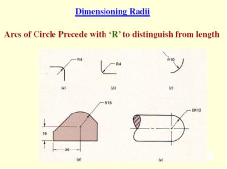
 Dimensioning and Locating Simple Features") Dimensioning 2-4) Dimensioning and Locating Simple Features Dimensioning Features a) A circle is dimensioned by its diameter and an arc by its radius using a leader line and a note. Exercise 2-6 Circular
Dimensioning 2-4) Dimensioning and Locating Simple Features Dimensioning Features a) A circle is dimensioned by its diameter and an arc by its radius using a leader line and a note. Exercise 2-6 Circular
Set No - 1 I B. Tech I Semester Regular/Supplementary Examinations Jan./Feb ENGINEERING DRAWING (EEE)
") Set No - 1 I B. Tech I Semester Regular/Supplementary Examinations Jan./Feb. - 2015 ENGINEERING DRAWING Time: 3 hours (EEE) Question Paper Consists of Part-A and Part-B Answering the question in Part-A
Set No - 1 I B. Tech I Semester Regular/Supplementary Examinations Jan./Feb. - 2015 ENGINEERING DRAWING Time: 3 hours (EEE) Question Paper Consists of Part-A and Part-B Answering the question in Part-A
2003 Academic Challenge
 Worldwide Youth in Science and Engineering 2003 Academic Challenge ENGINEERING GRAPHICS TEST - REGIONAL Engineering Graphics Test Production Team Ryan Brown, Illinois State University Author/Team Coordinator
1 ISOMETRIC PROJECTION SECTION I: INTRODUCTION TO ISOMETRIC PROJECTION
 1 ISOMETRIC PROJECTION SECTION I: INTRODUCTION TO ISOMETRIC PROJECTION Orthographic projection shows drawings of an object in a two-dimensional format, with views given in plan, elevation and end elevation
INSTITUTE OF AERONAUTICAL ENGINEERING
 Course Name Course Code Class Branch INSTITUTE OF AERONAUTICAL ENGINEERING Dundigal, Hyderabad - 500 043 MECHANICAL ENGINEERING TUTORIAL QUESTION BANK : ENGINEERING DRAWING : A10301 : I - B. Tech : Common
ENGINEERING GRAPHICS
 ENGINEERING GRAPHICS Time allowed : 3 hours Maximum Marks : 70 Note : (ii) Attempt all the questions. Use both sides of the drawing sheet, if necessary. (iii) All dimensions are in millimetres. (iv) Missing
GOVERNMENT POLYTECHNIC, VALSAD MECHANICAL ENGINEERING DEPARTMENT ASSIGNMENT SUB: MECHANICAL DRAFTING (C321901) TERM:172
 TERM:172") GOVERNMENT POLYTECHNIC, VALSAD MECHANICAL ENGINEERING DEPARTMENT ASSIGNMENT SUB: MECHANICAL DRAFTING (C321901) TERM:172 1) When all the dimension are placed above the dimension line, it is called (a) Aligned
GOVERNMENT POLYTECHNIC, VALSAD MECHANICAL ENGINEERING DEPARTMENT ASSIGNMENT SUB: MECHANICAL DRAFTING (C321901) TERM:172 1) When all the dimension are placed above the dimension line, it is called (a) Aligned
Contents. Notes on the use of this publication
 Contents Preface xxiii Scope Notes on the use of this publication xxv xxvi 1 Layout of drawings 1 1.1 General 1 1.2 Drawing sheets 1 1.3 Title block 2 1.4 Borders and frames 2 1.5 Drawing formats 2 1.6
Scale and Dimensioning (Architectural Board Drafting)
") Youth Explore Trades Skills Description In this activity, the teacher will first select an object that is larger than the page and scale it to fit in the designated drawing area to explain architectural
Youth Explore Trades Skills Description In this activity, the teacher will first select an object that is larger than the page and scale it to fit in the designated drawing area to explain architectural
Dimensioning in the figure below could be improved by: A
 1-Multiview-study Page 1 of 8 irections For Numbers 1-53 : Read each of the following multiple-choice items and the possible answers carefully. Mark the letter of the correct answer on your answer sheet
Geometric Dimensioning and Tolerancing
 Geometric Dimensioning and Tolerancing (Known as GDT) What is GDT Helps ensure interchangeability of parts. Use is dictated by function and relationship of the part feature. It does not take the place
the same information given in two different 1. Dimensions should NOT be duplicated, or Dimension Guidelines Incorrect ways.
 Dimension Guidelines 1. Dimensions should NOT be duplicated, or the same information given in two different ways. Incorrect 1. Dimensions should NOT be duplicated, or the same information given in two
Engineering Graphics- Basics.
 Engineering Graphics- Basics DRAWINGS: ( A Graphical Representation) The Fact about: If compared with Verbal or Written Description, Drawings offer far better idea about the Shape, Size & Appearance of
ISO INTERNATIONAL STANDARD. Technical drawings General principles of presentation Part 24: Lines on mechanical engineering drawings
 INTERNATIONAL STANDARD ISO 128-24 First edition 1999-06-01 Technical drawings General principles of presentation Part 24: Lines on mechanical engineering drawings Dessins techniques Principes généraux
2. Line composed of closely and evenly spaced short dashes in a drawing represents
 1. Hidden lines are drawn as (a) dashed narrow lines (b) dashed wide lines (c) long-dashed dotted wide line (d) long-dashed double dotted wide line Ans: (a) 2. Line composed of closely and evenly spaced
Chapter 6. Architectural Lines and Lettering
 Chapter 6 Architectural Lines and Lettering Drafting Introduction Universal graphic language Uses lines, symbols, dimensions, and notes to describe a structure to be built Properly drawn lines are dark,
Engineering Working Drawings Basics
 Engineering Working Drawings Basics Engineering graphics is an effective way of communicating technical ideas and it is an essential tool in engineering design where most of the design process is graphically
UNIT 5a STANDARD ORTHOGRAPHIC VIEW DRAWINGS
 UNIT 5a STANDARD ORTHOGRAPHIC VIEW DRAWINGS 5.1 Introduction Orthographic views are 2D images of a 3D object obtained by viewing it from different orthogonal directions. Six principal views are possible
Sectional Views. DFTG-1305 Technical Drafting by Prof. Francis Ha. Session 6. Geisecke s textbook: 14 th Ed. Chapter 7 p th Ed. Chapter 8 p.
 DFTG-1305 Technical Drafting by Prof. Francis Ha Session 6 Sectional Views Geisecke s textbook: 14 th Ed. Chapter 7 p.242 15 th Ed. Chapter 8 p.326 Update: 18-10007 What is this? An ugly rock? Sectional
Introduction CHAPTER Graphics: A Tool to Communicate Ideas
 CHAPTER 1 Introduction 1.1 Graphics: A Tool to Communicate Ideas Engineering graphics or drawing is the universal language of engineers. An engineer communicate his idea to others with the help of this
Surface Developments. Sacramento City College Engineering Design Technology. Surface Developments 1
 Surface Developments Sacramento City College Engineering Design Technology Surface Developments 1 Surface Developments A surface development is a full-size layout of an object made on a single flat plane.
Pictorial Drawings. DFTG-1305 Technical Drafting Prepared by Francis Ha, Instructor
 DFTG-1305 Technical Drafting Prepared by Francis Ha, Instructor Pictorial Drawings Geisecke s textbook for reference: 14 th Ed. Ch. 15: p. 601 Ch. 16: p. 620 15 th Ed. Ch. 14: p. 518 Ch. 15: p. 552 Update:
ISOMETRIC PROJECTION. Contents. Isometric Scale. Construction of Isometric Scale. Methods to draw isometric projections/isometric views
 ISOMETRIC PROJECTION Contents Introduction Principle of Isometric Projection Isometric Scale Construction of Isometric Scale Isometric View (Isometric Drawings) Methods to draw isometric projections/isometric
4. Draw the development of the lateral surface of the part P of the cylinder whose front view is shown in figure 4. All dimensions are in cm.
 Code No: Z0122 / R07 Set No. 1 I B.Tech - Regular Examinations, June 2009 ENGINEERING GRAPHICS ( Common to Civil Engineering, Mechanical Engineering, Chemical Engineering, Bio-Medical Engineering, Mechatronics,
Mechanical Engineering Drawing
 Mechanical Engineering Drawing MECH 211 LECTURE 3 Contents of the lecture Shape description Shape generation Sectional views Auxiliary views Shape description Geometric shapes are seen according to view
Technological Design Mr. Wadowski. Orthographic & Isometric Drawing Lesson
 Technological Design Mr. Wadowski Orthographic & Isometric Drawing Lesson TOPICS Working Drawings, Isometric Drawings & Orthographic Drawings Glass box concept Multiview projection Orthographic projection
Introduction to Sheet Metal Features SolidWorks 2009
 SolidWorks 2009 Table of Contents Introduction to Sheet Metal Features Base Flange Method Magazine File.. 3 Envelopment & Development of Surfaces.. 14 Development of Transition Pieces.. 23 Conversion to
E GRAPHICS ISOMETRIC PROJECTIONS S.RAMANATHAN ASST PROF MVSREC PH: CONCEPTS.
 E GRPHIS ISOMETRI PROJETIONS S.RMNTHN SST PROF MVSRE ONEPTS. Isometric projections are 3-D representation of objects. Since we deal mostly with solids which are 3-D objects, we use isometric projections
Fundamentals of Drafting - Orthographic Projection with Hidden Details
 Fundamentals of Drafting - Orthographic Projection with Hidden Details Objectives: 1. To extend the principle of orthographic projection for hidden details. 2. To illustrate the representation of hidden
INTERMEDIATE LEVEL MEASUREMENT
 INTERMEDIATE LEVEL MEASUREMENT TABLE OF CONTENTS Format & Background Information...3-6 Learning Experience 1- Getting Started...6-7 Learning Experience 2 - Cube and Rectangular Prisms...8 Learning Experience
Standards for Your Career Field
 Dimensioning Dimensions Dimensions are used to describe the sizes and relationships between features in your drawing. Dimensions are used to manufacture parts and to inspect the resulting parts to determine
AutoCAD Tutor 2011 Support Docs
 AutoCAD Tutor 2011 Support Docs CHAPTER 1 CUSTOMIZING THE QUICK ACCESS TOOLBAR One of the advantages of the Quick Access Toolbar is the ability to display the AutoCAD commands that you frequently use.
Part 1: General principles
 Provläsningsexemplar / Preview INTERNATIONAL STANDARD ISO 129-1 Second edition 2018-02 Technical product documentation (TPD) Presentation of dimensions and tolerances Part 1: General principles Documentation
DESIGN & COMMUNICATION GRAPHICS
 photograph of three balls is shown. ll three are in mutual contact and rest on the horizontal plane. The centres of the two larger ones lie in a line which is parallel to the vertical plane. The drawing
Geometrical product specifications (GPS) Geometrical tolerancing Tolerances of form, orientation, location and run-out
 Geometrical tolerancing Tolerances of form, orientation, location and run-out") Provläsningsexemplar / Preview INTERNATIONAL STANDARD ISO 1101 Fourth edition 2017-02 Geometrical product specifications (GPS) Geometrical tolerancing Tolerances of form, orientation, location and run-out
Provläsningsexemplar / Preview INTERNATIONAL STANDARD ISO 1101 Fourth edition 2017-02 Geometrical product specifications (GPS) Geometrical tolerancing Tolerances of form, orientation, location and run-out
. These are not necessarily. There is much more to the, as we will see.
 Dimensioning Study Guide (Study Chapter 11 in Technical Drawing) 1. In addition to a complete shape description of an object... a drawing of the design must also give a complete ; that is, it must be.
Starting a 3D Modeling Part File
 1 How to Create a 3D Model and Corresponding 2D Drawing with Dimensions, GDT (Geometric Dimensioning and Tolerance) Symbols and Title Block in SolidWorks 2013-2014 By Edward Locke This tutorial will introduce
ENGINEERING DRAWING. UNIT III - Part A
 DEVELOPMENT OF SURFACES: ENGINEERING DRAWING UNIT III - Part A 1. What is meant by development of surfaces? 2. Development of surfaces of an object is also known as flat pattern of the object. (True/ False)
Engineering Graphics. Class 2 Drafting Instruments Mohammad Kilani
 Engineering Graphics Class 2 Drafting Instruments Mohammad Kilani Drafting Instruments A Design is as good as its instruments A engineering drawing is a highly stylized graphic representation of an idea.
2018 Technical Drawing Specifications Resource A guide to support VCE Visual Communication Design Study Design
 2018 Technical Drawing Specifications Resource A guide to support VCE Visual Communication Design Study Design 2018 22 VICTORIAN CURRICULUM AND ASSESSMENT AUTHORITY 1 Contents A guide to support VCE Visual
CE 100 Civil Engineering Drawing Sessional (Lab Manual)
") CE 100 Civil Engineering Drawing Sessional (Lab Manual) Department of Civil Engineering Ahsanullah University of Science and Technology November, 2017 1 Preface This course is designed to provide civil
CE 100 Civil Engineering Drawing Sessional (Lab Manual) Department of Civil Engineering Ahsanullah University of Science and Technology November, 2017 1 Preface This course is designed to provide civil
1. Open the Feature Modeling demo part file on the EEIC website. Ask student about which constraints needed to Fully Define.
 BLUE boxed notes are intended as aids to the lecturer RED boxed notes are comments that the lecturer could make Control + Click HERE to view enlarged IMAGE and Construction Strategy he following set of
Contents. Foreword. Using this Guide
 Foreword xv Preface xvii Scope Using this Guide xix xix 1 Specifying technical products 1 1.1 What is meant by technical product specification? 1 1.2 Design brief 1 1.3 Function 1 1.4 Specifications 2
Geometrical product specifications (GPS) Geometrical tolerancing Tolerances of form, orientation, location and run-out
 Geometrical tolerancing Tolerances of form, orientation, location and run-out") INTERNATIONAL STANDARD ISO 1101 Fourth edition 2017-02 Geometrical product specifications (GPS) Geometrical tolerancing Tolerances of form, orientation, location and run-out Spécification géométrique des
INTERNATIONAL STANDARD ISO 1101 Fourth edition 2017-02 Geometrical product specifications (GPS) Geometrical tolerancing Tolerances of form, orientation, location and run-out Spécification géométrique des
2012 Academic Challenge
 2012 Academic Challenge ENGINEERING GRAPHICS TEST STATE FINAL This Test Consists of 40 Questions Engineering Graphics Test Production Team Ryan Brown, Illinois State University Author/Team Leader Jacob
At the conclusion of this unit you should be able to accomplish the following with a 70% accuracy
 7 Multiview Drawing OBJECTIVES At the conclusion of this unit you should be able to accomplish the following with a 70% accuracy 1. explain the importance of mulitview drawing as a communication tool far
Trade of Metal Fabrication. Module 3: Plate Fabrication Unit 12: Duct Sections Phase 2
 Trade of Metal Fabrication Module 3: Plate Fabrication Unit 12: Duct Sections Phase 2 Table of Contents List of Figures... 4 List of Tables... 5 Document Release History... 6 Module 3 Plate Fabrication...
ORTHOGRAPHIC PROJECTION
 ORTHOGRAPHIC PROJECTION C H A P T E R S I X OBJECTIVES 1. Recognize and the symbol for third-angle projection. 2. List the six principal views of projection. 3. Understand which views show depth in a drawing
Chapter 1 Introduction
 Chapter 1 Introduction Contents Engineering drawing Drawing standards Drawing sheet Scale Lettering Line types Engineering Drawing Contents Engineering Drawing Effectiveness of Graphic Language 1. Try
Orthographic Projection 1
 Orthographic Projection 1 What Is Orthographic Projection? Basically it is a way a representing a 3D object on a piece of paper. This means we make the object becomes 2D. The difference between Orthographic
Describing an Angle Bracket
 Basics of Drafting Describing an Angle Bracket Orthographic Projection Orthographic drawings represent three dimensional objects in three separate views arranged in a standard manner. Orthographic Views
VCE VET Engineering Studies: Certificate II Engineering Studies Written examination
 Introduction VCE VET Engineering Studies: Certificate II Engineering Studies Written examination The following sample examination is provided to demonstrate the format and types of questions which will
C A R I B B E A N E X A M I N A T I O N S C O U N C I L REPORT ON CANDIDATES WORK IN THE SECONDARY EDUCATION CERTIFICATE EXAMINATION MAY/JUNE 2010
 C A R I B B E A N E X A M I N A T I O N S C O U N C I L REPORT ON CANDIDATES WORK IN THE SECONDARY EDUCATION CERTIFICATE EXAMINATION MAY/JUNE 2010 TECHNICAL DRAWING GENERAL PROFICIENCY Copyright 2010 Caribbean
DELHI TECHNOLOGICAL UNIVERSITY ENGINEERING GRAPHICS LAB MANUAL
 DELHI TECHNOLOGICAL UNIVERSITY ENGINEERING GRAPHICS LAB MANUAL NAME: - ROLL NO: - GROUP: - BRANCH: - GROUP TEACHER: Page 1 www.rooplalrana.com 1 GENERAL INSTRUCTIONS FOR ENGG. GRAPHICS LAB 1) Students
ENGINEERING GRAPHICS 1.0 Introduction Engineering Graphics Drawing as an art Artist Graphic design Engineering graphics engineering drawing
 ENGINEERING GRAPHICS 1.0 Introduction Engineering is the profession in which the knowledge of mathematics and science gained by study, experience and practice is applied with good judgment to develop a