CE 100 Civil Engineering Drawing Sessional (Lab Manual)
|
|
|
- Juniper Douglas
- 6 years ago
- Views:
Transcription
1 CE 100 Civil Engineering Drawing Sessional (Lab Manual) Department of Civil Engineering Ahsanullah University of Science and Technology November,
2 Preface This course is designed to provide civil engineering undergraduates with basic understanding of the theory and practice of engineering drawings. Students will learn to read and construct all architectural, structural and other drawings by means of discussions and drawing examples related to existing buildings or projects. It includes lettering, plane geometry, different geometric constructions, types of lines, perspective projections, orthographic projections, structural floor plan of a building and detailing for typical reinforced concrete structural members. This Lab manual was prepared with the help of Beginner s guide to Engineering Drawing by Dr. E. R. Latifee and some other lecture notes. Md. Asif Hossain Department of Civil Engineering Ahsanullah University of Science and Technology Updated by Md. Ajwad Anwar Sudipta Dey Tirtha Syed Aaqib Javed Department of Civil Engineering Ahsanullah University of Science and Technology 2
3 Table of Contents Traditional Drawing Tools... 4 Standard Engineering Lettering... 7 Different Geometric Constructions Types of Lines Perspective Projections Orthographic Projections and Isometric Drawing Structural drawing Plan view, Elevation view and Cross sectional view Structural drawing Isolated footing and beam longitudinal and cross sectional views Structural drawing Slab and Stair reinforcement detailing Appendix Appendix

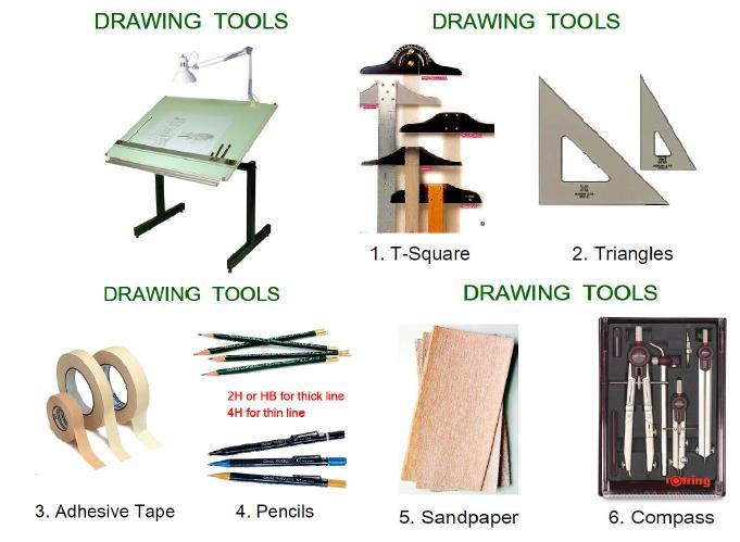
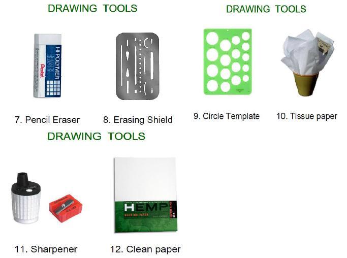
4 Topic 1 Traditional Drawing Tools 4

5 Drawing A drawing is a graphic representation of an object, or a part of it, and is the result of creative thought by an engineer or technician. When one person sketches a rough map in giving direction to another, this is graphic communication. Graphic communication involves using visual materials to relate ideas. Drawings, photographs, slides, transparencies, and sketches are all forms of graphic communication. Any medium that uses a graphic image to aid in conveying a message, instructions, or an idea is involved in graphic communication. Engineering drawing: The engineering drawing, on the other hand, is not subtle, or abstract. It does not require an understanding of its creator, only an understanding of engineering drawings. An engineering drawing is a means of clearly and concisely communicating all of the information necessary to transform an idea or a concept in to reality. Therefore, an engineering drawing often contains more than just a graphic representation of its subject. It also contains dimensions, notes and specifications. 5
6 6

7 Topic 2 Standard Engineering Lettering 7


8 Elements of Engineering Drawing Engineering drawing are made up of graphics language and word language. Graphics language: Describe a shape (mainly). Word language: Describe an exact size, location and specification of the object. 8
9 Lettering in Engineering Drawing Lettering is used to provide easy to read and understand information to supplement a drawing in the form of notes and annotations. Lettering is an essential element in both traditional drawing and Computer Aided Design (CAD) drawing. Thus, it must be written with: Legibility shape & space between letters and words. Uniformity size & line thickness. Types of Lettering The two types of lettering are: 1. Double Stroke Lettering: In Double Stroke Lettering the line width is greater than that of Single Stroke Lettering. Double Stroke Lettering is further divided into: a) Double Stroke Vertical Gothic Lettering. b) Double Stroke Inclined Gothic Lettering. A stencil is mostly used when hand drawing double stroked letters. 2. Single Stroke Lettering: Thickness in single stroke lettering is obtained by a single stroke of pencil or ink pen. It is further divided into: (a) Single Stroke Vertical Gothic Lettering. (b) Single Stroke Inclined Gothic Lettering. Conventions for Lettering Use all CAPITAL LETTERS. Use even pressure to draw precise, clean lines. Use one stroke per line. Horizontal Strokes are drawn left to right. Vertical Strokes are drawn downward. Curved strokes are drawn top to bottom in one continuous stroke on each side. Use The Single-stroke, Gothic Style of Lettering. Always Skip A Space Between Rows Of Letters. Always Use Very Light Guide Lines. Fractions Are Lettered Twice the Height Of Normal Letters. Fraction Bars Are Always Drawn Horizontal. Use a Medium Lead For Normal Lettering. Use a Hard Lead For Drawing Guide Lines. 9
10 Placement of Text on Engineering Drawings 10


11 Basics of Single Stroking Spacing Uniformity in spacing of letters is a matter of equalizing spaces by eye. The background area between letters, not the distance between them, should be approximately equal. Words are spaced well apart, but letters within words should be spaced closely. For either upper case or lower-case lettering, make the spaces between words approximately equal to a capital O. 11


12 Space between letters Drawing scales Scale is the ratio of the linear dimension of an element of an object shown in the drawing to the real linear dimension of the same element of the object. 12

13 Designation of a scale consists of the word SCALE followed by the indication of its ratio, as follows: Dimension numbers shown in the drawing correspond to true size of the object and they are independent of the scale used in creating that drawing. 13
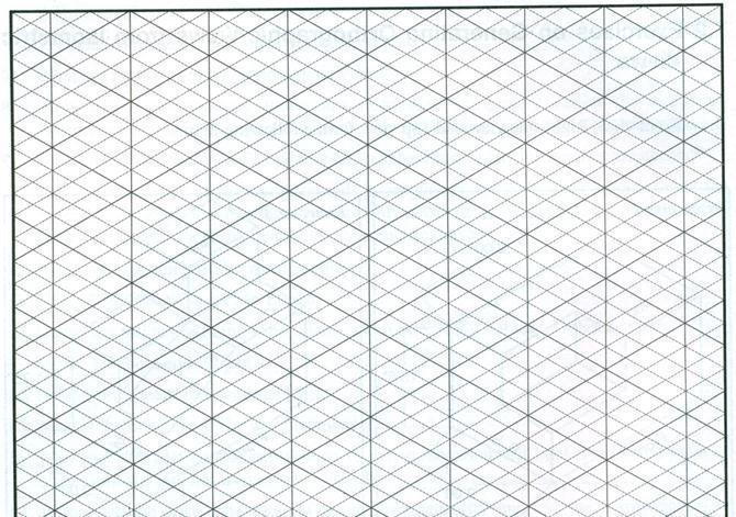
 inches distance between the lines, in both the")
14 Try with one-fourth (0.25) inches distance between the lines, in both the directions (X and Y axes) 14

15 Topic 3 Different Geometric Constructions 15
16 Objectives: At the end of this chapter students should be able to: Define geometric nomenclatures like angles, lines etc Discuss the steps to construct different geometric figures like lines, arcs, polygon, ellipse etc. Introduction : Strict interpretation of geometric construction allows use of only the compass and an instrument for drawing straight lines, and with these, the geometer, following mathematical theory, accomplishes his solutions. In technical drawing, the principles of geometry are employed constantly, but instruments are not limited to the basic two as T-squares, triangles, scales, curves etc. are used to make constructions with speed and accuracy. Since there is continual application of geometric principles, the methods given in this chapter should be mastered thoroughly. GEOMETRIC NOMENICLATURE A. POINTS IN SPACE A point is an exact location in space or on a drawing surface. A point is actually represented on the drawing by a crisscross at its exact location. The exact point in space is where the two lines of the crisscross intersect. When a point is located on an existing line, a light, short dashed line or cross bar is placed on the line at the location of the exact point. Never represent a Point on a drawing by a dot; except for sketching locations. B. LINE Lines are straight elements that have no width, but are infinite in length (magnitude), and they can be located by two points which are not on the same spot but fall along the line. Lines may be straight lines or curved lines. A straight line is the shortest distance between two points. It can be drawn in any direction. If a line is indefinite, and the ends are not fixed in length, the actual length is a matter of convenience. If the end points of a line are important, they must be marked by means of small, mechanically drawn crossbars, as described by a pint in space. Straight lines and curved lines are considered parallel if the shortest distance between them remains constant. The symbol used for parallel line is //. Lines, which are tangent and at 90 degree are considered perpendicular. The symbol for perpendicular line is. C. ANGLES An angle is formed by the intersection of two lines. There are three major kinds of angles: right angels, acute angles and obtuse angles. The right angle is an angle of 900, an acute angle is an angle less than 900, and an obtuse angle is an angle more than 900. A straight line is The symbol for an angle is < (singular) and < s (Plural). To draw an angle, use the drafting machine, a triangle, or a protractor. 16


17 D. TRIANGLES A triangle is a closed plane figure with three straight sides and their interior angles sum up exactly The various kinds of triangles: a right triangle, an equilateral triangle, an isosceles triangle, and an obtuse angled triangle. E. QUADRIALTERAL It is a plane figure bounded by four straight sides. When opposite sides are parallel, the quadrilateral is also considered to be a parallelogram. F. POLYGON A polygon is a closed plane figure with three or more straight sides. The most important of these polygons as they relate to drafting are probably the triangle with three sides, square with four sides, the hexagon with six sides, and the octagon with eight sides. 17


18 F1. Regular Pentagon F2. Regular Hexagon 18


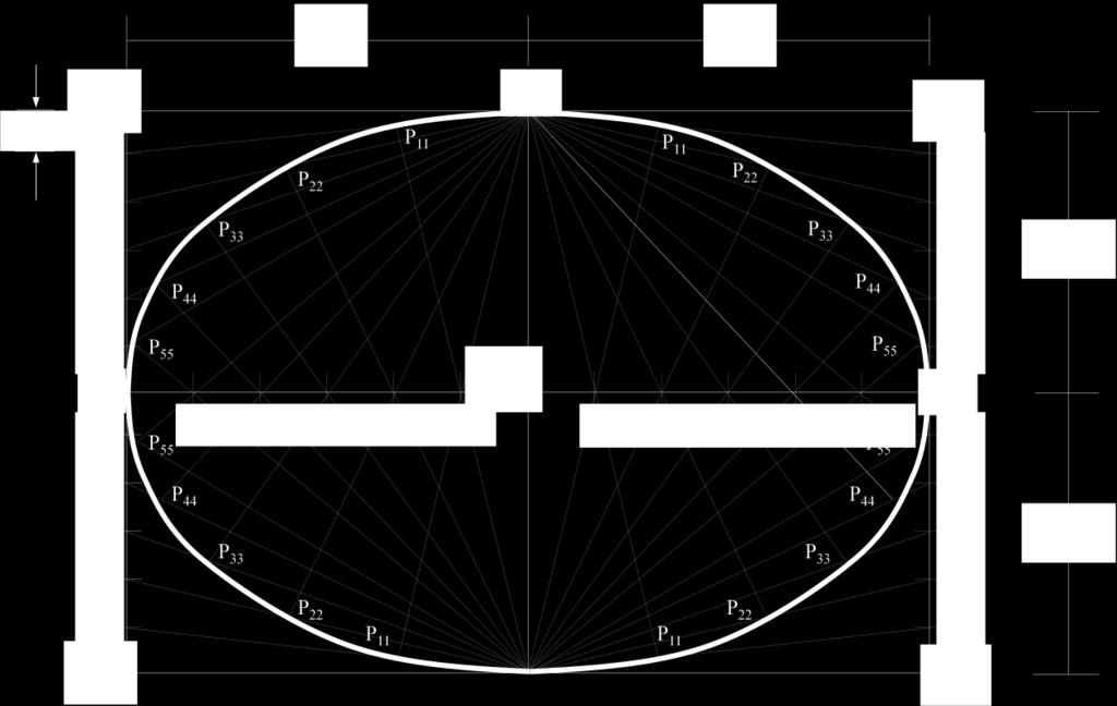
19 F3. Regular Octagon G1. Ellipse (Parallelogram Method) 19

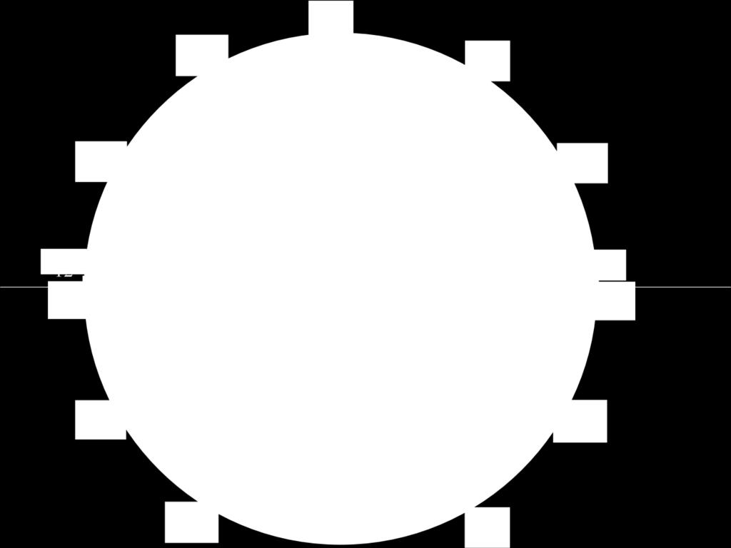
20 G2. Ellipse Concentric Circles Method H. Hyperbola 20

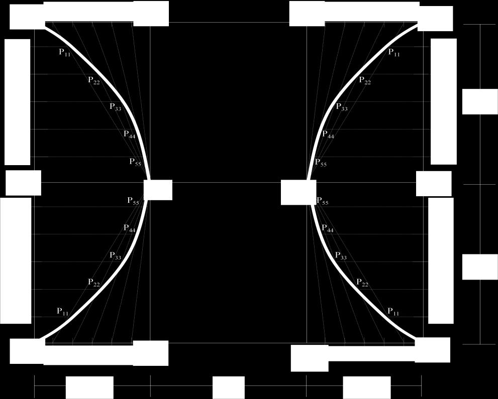
21 I. PARABOLA 21
22 Topic 4 Types of Lines 22
23 Introduction to Types of Lines 23


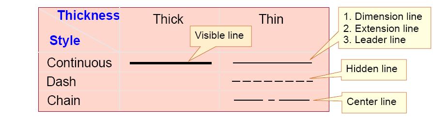
24 Visible/Object Lines Dark, heavy lines. Used to represent the outline or contour of the object being drawn. Define features you can see in a particular view. Hidden Lines Light, narrow, short, dashed lines. Shows the outline of a feature that cannot be seen in a particular view. Used to help clarify a feature, but can be omitted if they clutter a drawing. Hidden lines should always begin and end with a dash. Exception: When the hidden line begins or ends at a parallel visible or hidden line. Dashes should join at corners. 24
25 Section Lines Thin line usually drawn at a 45 degree angle. Indicates the material that has been cut through in a sectional view. Center Lines Thin line consisting of alternating long and short dashes. Used to represent the center of round or cylindrical features, or the symmetry of a feature. Center lines should start and end with long dashes. 25
26 Center lines should intersect by crossing either the long dashes or the short dashes. Center lines should extend a short distance beyond the object or feature. Center lines may be connected within a single view to show that two or more features lie in the same plane. Center lines should not extend through the space between views. Dimension Lines Thin lines capped on the ends with arrowheads and broken along their length to provide a space for the dimension numeral. They indicate length. 26
27 Extension Lines Thin lines used to establish the extent of a dimension. Can also be used to show extension of a surface to a theoretical intersection as shown in (b). Begin 1.5mm from the object and extend to 3mm beyond the last dimension. They should not cross dimension lines. Leader Lines Thin lines used to connect a specific note to a feature. Also used to direct dimensions, symbols, item number and part numbers on a drawing. Commonly drawn at 45, 30 and 60 degrees. Has a short shoulder (3-6mm) at one end beginning at the center of the vertical height of text, and a standard dimension arrowhead at the other end touching the feature. Leader lines should not cross each other. Leader lines should not be excessively long. Leader lines should not be vertical or horizontal. Leader lines should not be parallel to dimension lines, extension lines or section lines. Arrowheads Used to terminate dimension lines and leader lines and on cutting-plane lines and viewing plane lines. They should be three times as long as they are wide. They should be the same size throughout the drawing. The filled arrowhead is generally preferred because of its clarity. 27
 Short Break Lines. Thick wavy line.")
28 Cutting Plane Lines Thick broken line that is terminated with short 90 degree arrowheads. Shows where a part is mentally cut in half to better see the interior detail. Break Lines Break Lines are used to break out sections for clarity or for shortening a part. Three types of break lines with different line weights: a) Short Break Lines. Thick wavy line. Used to break the edge or surface of a part for clarity of a hidden surface. 28

 Cylindrical Break Lines.")

29 b) Long Break Lines Long, thin lines. Used to show that the middle section of an object has been removed so it can be drawn on a smaller piece of paper. c) Cylindrical Break Lines. Thin lines. Used to show round parts that are broken in half to better clarify the print or to reduce the length of the object. 29


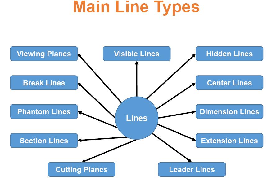
30 Phantom Lines Thin lines made up of long dashes alternating with pairs of short dashes. Three purposes in drawings: To show the alternate position of moving parts. To show the relationship of parts that fit together. To show repeated detail. Line Precedence If two lines occur in the same place, the line that is considered to be the least important is omitted. Lines in order of precedence/importance are as follows: - Cutting plane line - Visible line - Hidden line - Centerline 30
31 Example 31
32 32
33 Topic 5 Perspective Projections 33
 Points to be considered, - Location of object - Location of observer - Plane of projection - Projectors/lines of projection")
34 Projection Projections transform points from n (here, n = 3) dimensional space into a space of dimension less than n (here, n = 2) Points to be considered, - Location of object - Location of observer - Plane of projection - Projectors/lines of projection 34


35 Parallel Projections Parallel Projection is a type of projection where the line of sight or projectors are parallel and are perpendicular to the picture planes. It is subdivided in to the following three categories: Orthographic, Oblique and Axonometric Projections. Orthographic projections: are drawn as multi view drawings, which show flat representations of principal views of the subject. Oblique Projections: actually show the full size of one view. Axonometric Projections: are three-dimensional drawings, and are of three different varieties: Isometric, Dimetric and Trimetric. Orthographic Projections Orthographic projections are drawings where the projectors, the observer or station point remain parallel to each other and perpendicular to the plane of projection. Orthographic projections are further subdivided into axonometric projections and multiview projections. Effective in technical representation of objects. 35


 is parallel to the plane of projection.")
36 Oblique Projections Projectors are parallel to each other but not perpendicular to projection plane. An oblique projection shows front and top surfaces that include the three dimensions of height, width, and depth. The front or principal surface of an object (the surface toward the plane of projection) is parallel to the plane of projection. Effective in pictorially representing objects. Perspective Projections Figure: Oblique drawing 36


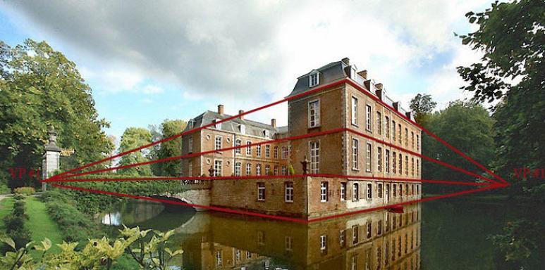
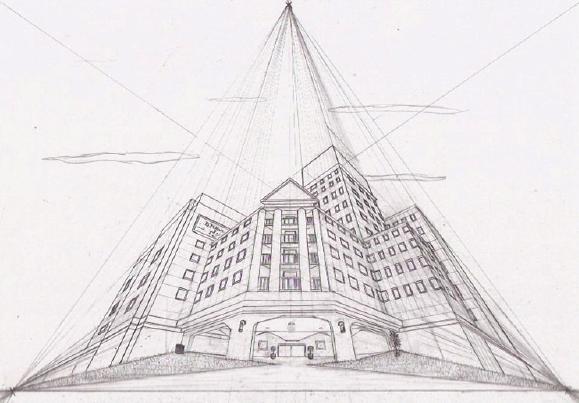
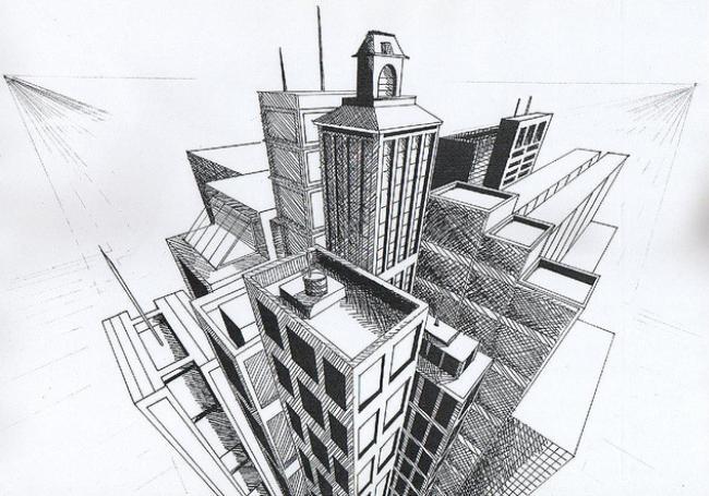
37 Perspective projections are drawings which attempt to replicate what the human eye actually sees when it views an object. There are three types of perspective projections: One-point, Two-point and Three-point Projections. Three point perspective projection: Figure: Perspective projection Some real world examples of one 1 point, 2 point and 3 point Perspective projection: 37

38 Figure: One Point Perspective Projections 38

39 Figure: Two Point Perspective Projections 39
40 40


41 Figure: Three Point Perspective Projections 41
42 Topic 6 Orthographic Projections and Isometric Drawing 42
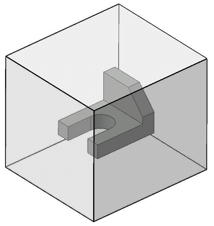
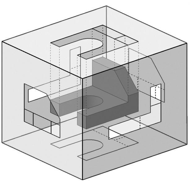
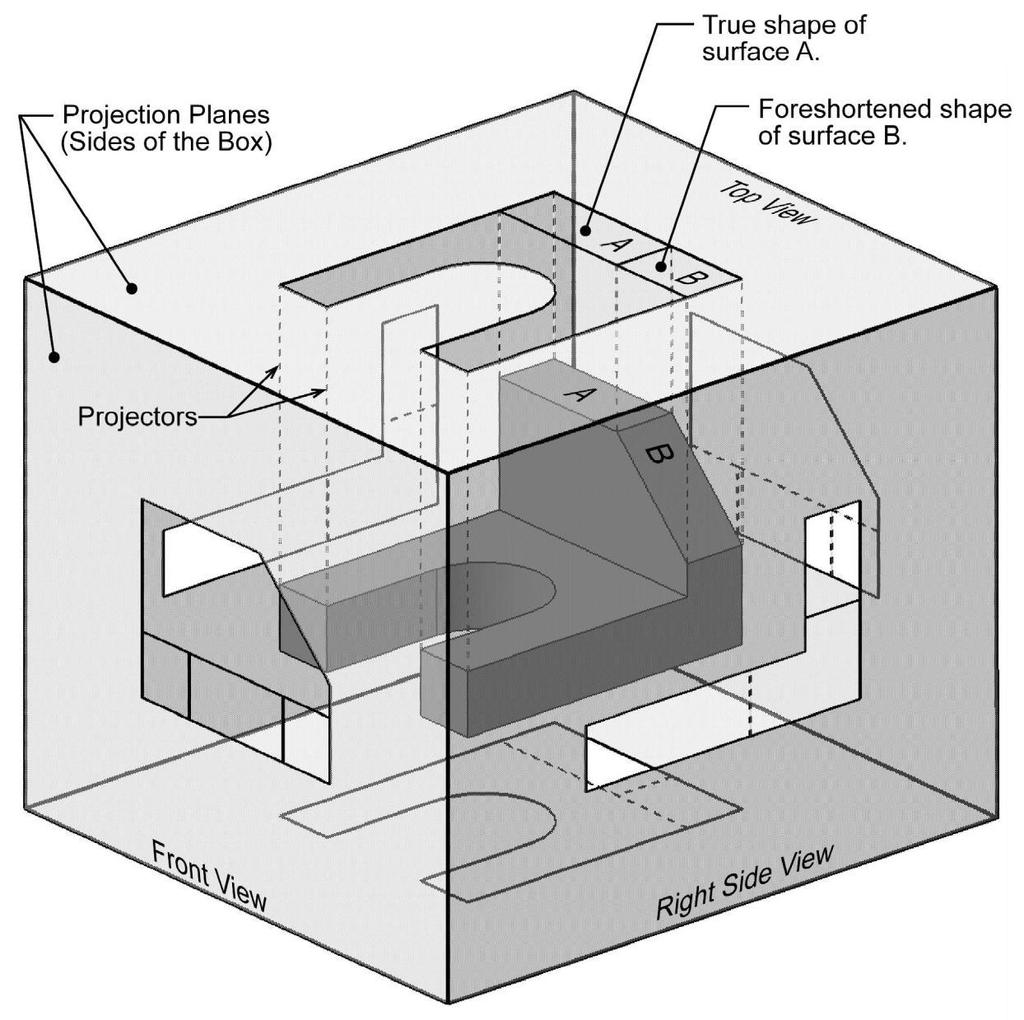
43 Introduction Orthographic projection = 2-D representation of a 3-D object. The Six Principal Views The 6 principal views are created by looking at the object, straight on, in the directions indicated. The Glass Box Method The object is placed in a glass box. The sides of the box represent the 6 principal planes. The image of the object is projected on the sides of the box. Things to notice: The projection planes. The projectors. How surfaces A and B are projected. The box is unfolded creating the 6 principal views. 43
44 44


45 Standard Views When constructing an orthographic projection, we need to include enough views to completely describe the true shape of the part. Complex part = more views Simple part = less views Front View The front view shows the most features or characteristics of the object. - It usually contains the least amount of hidden lines. - The front view is chosen first and the other views are based on the orientation of the front view. View Alignment The top and front views are aligned vertically and share the same width dimension. The front and right side views are aligned horizontally and share the same height dimension. 45
46 1. 46
47 2. 47
48 3. 48
49 4. 49
50 5. 50
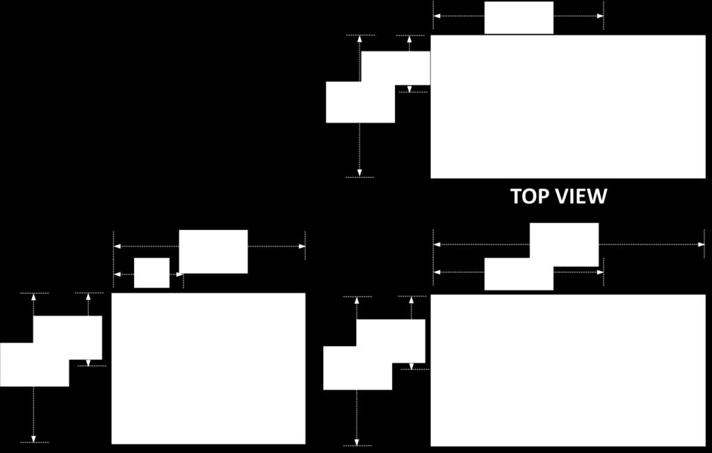
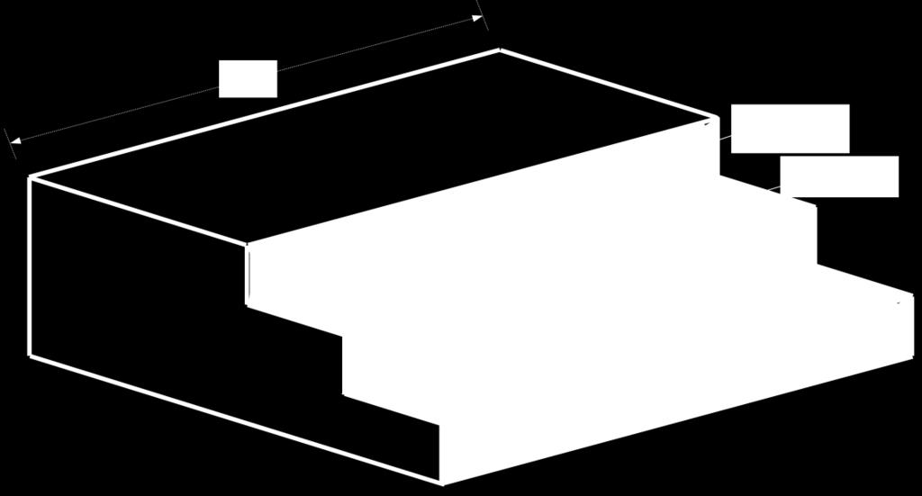
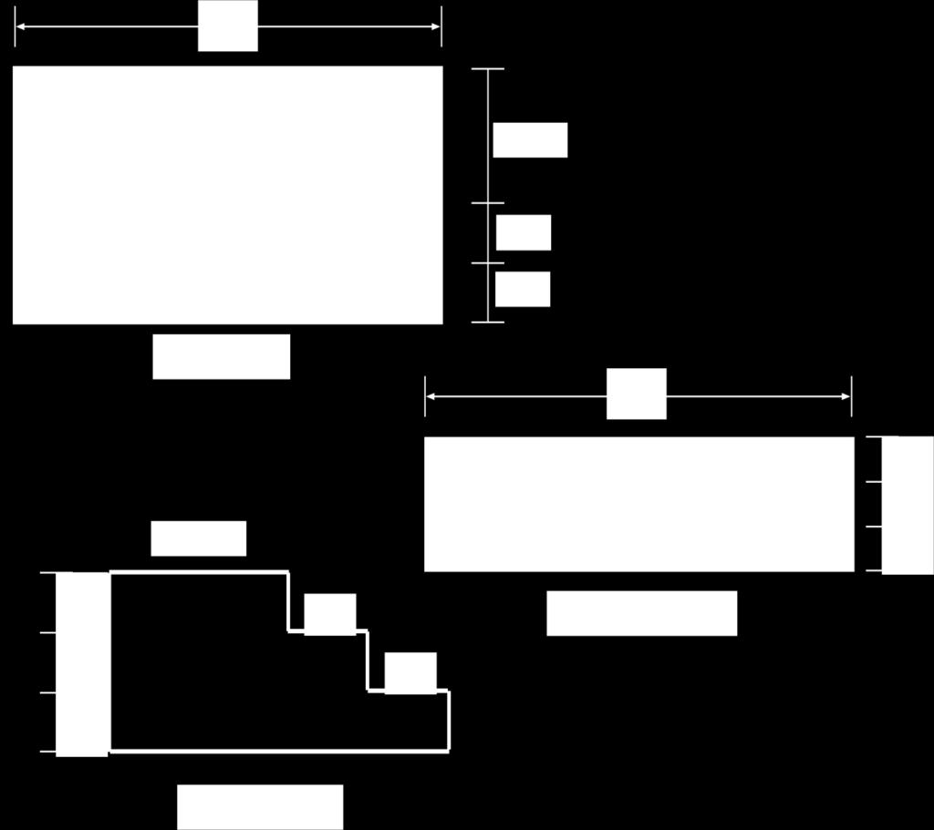
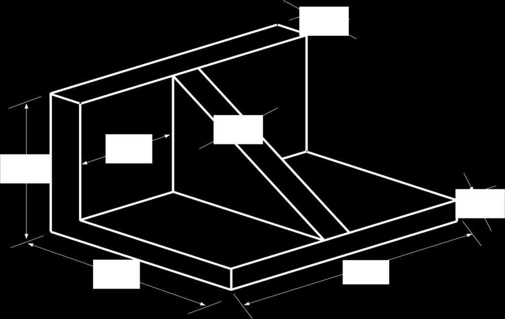
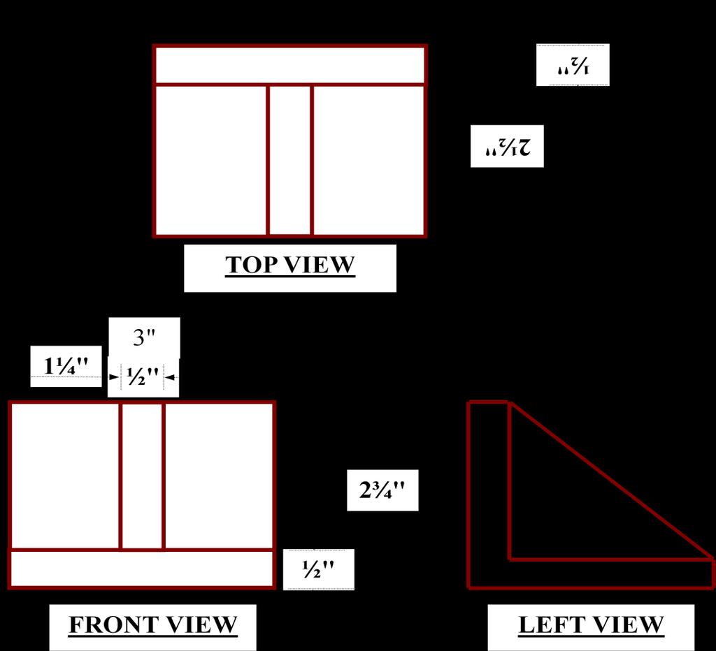
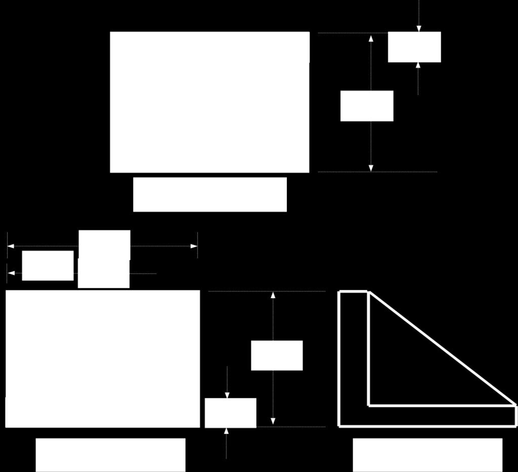
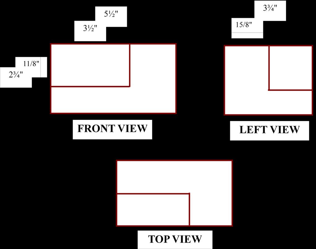
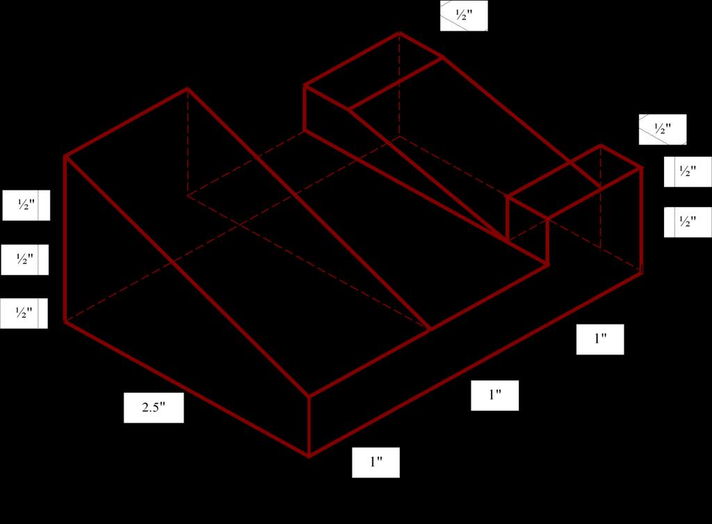
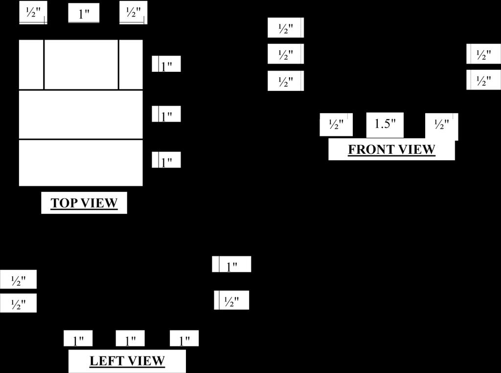
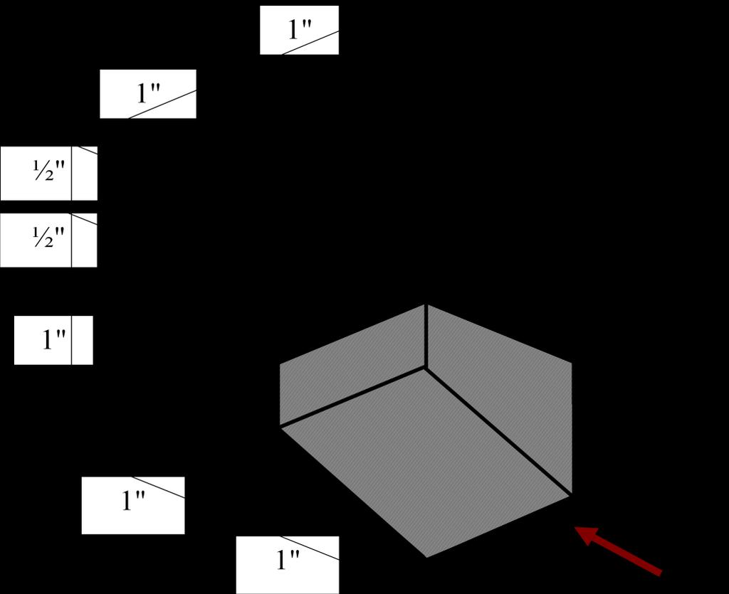
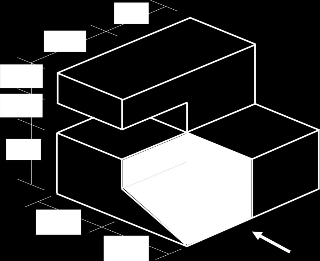
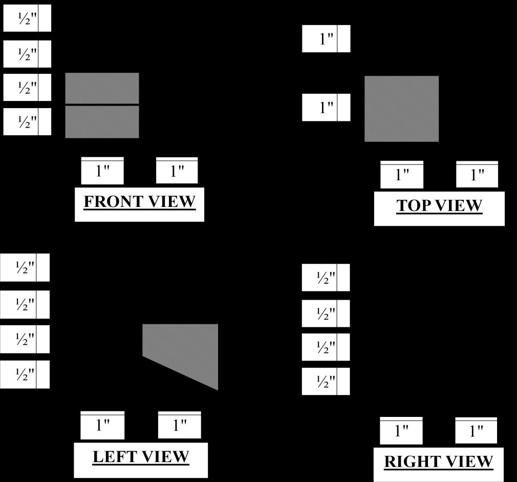
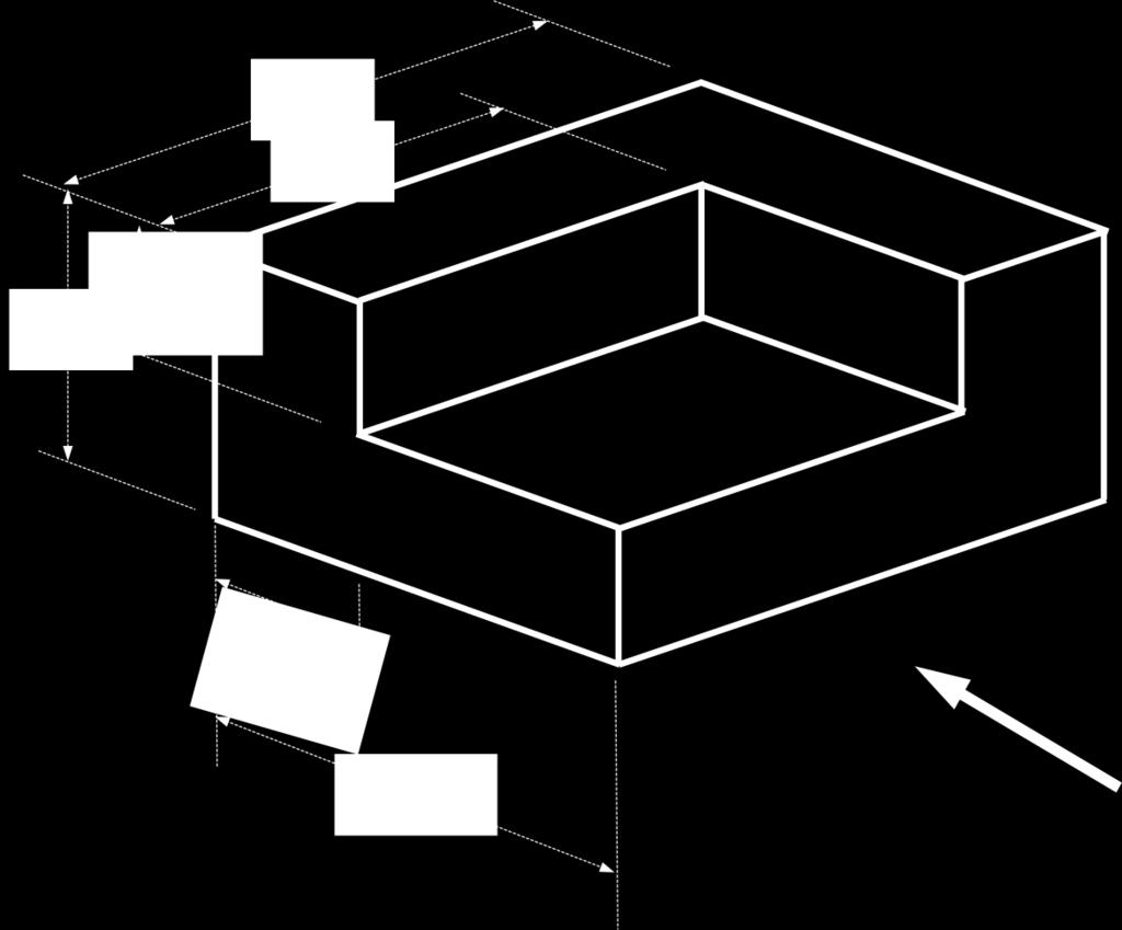
51 Orthographic to Isometric Drawing 51
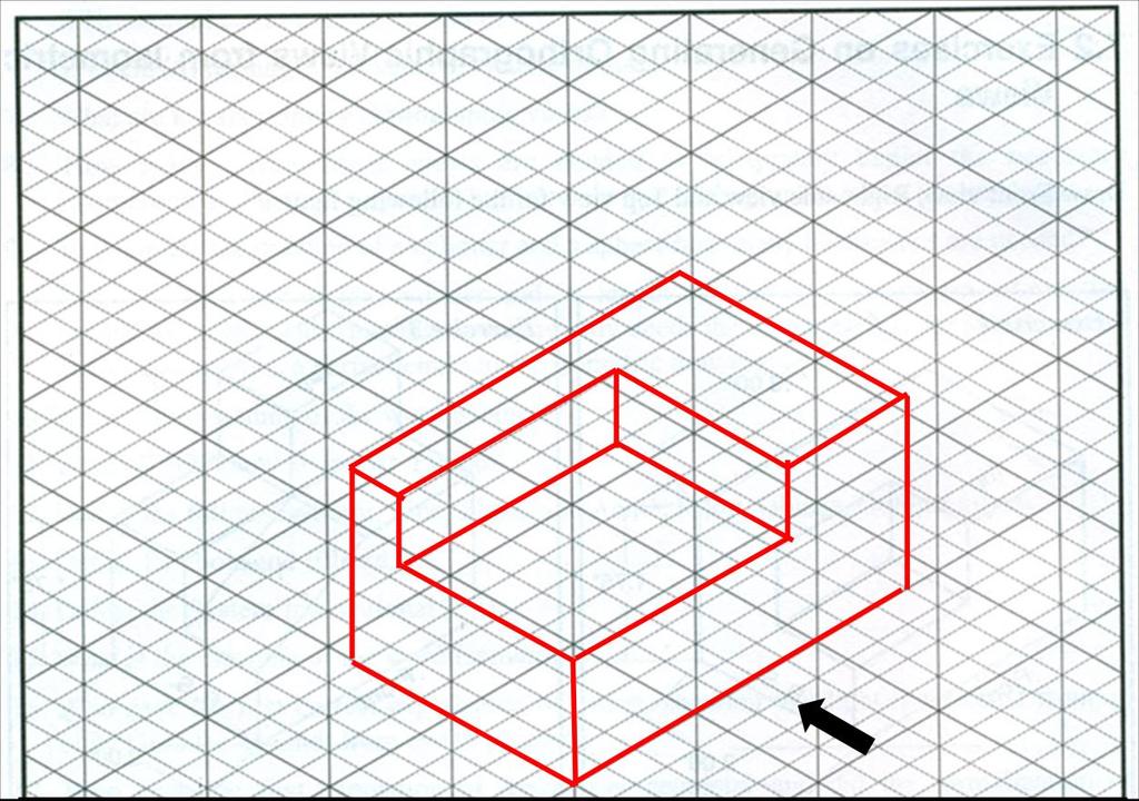
52 52
53 53
54 Assignment 54

55 Topic 7 Structural drawing Plan view, Elevation view and Cross sectional view 55
56 56
57 57
58 58
59 59
60 60


61 Topic 8 Structural drawing Isolated footing and beam longitudinal and cross sectional views 61
62 Cross Section of an Isolated column footing 62
63 63


64 Topic 9 Structural drawing Slab and Stair reinforcement detailing 64
65 65
66 66
67 Appendix 1 Lab Report Format 1. All students must have a same colored printed cover page. The design of cover page is provided with the lab manual. Students have to compose only the course teacher s name and designation and their information. 2. An index is provided. It should be printed and set after the cover page. Table may be filled up by pen during each submission after that particular subject has been covered. 3. Each report must have a common top page. Only the experiment name and no. and the date may be filled up by pen. A top page design is provided. 4. A4 papers have to be used for preparing the lab report. 67
68 CE 100 Civil Engineering Drawing Sessional (Lab Report) Prepared For Name of Course Teacher Designation of Course Teacher & Name of Course Teacher Designation of Course Teacher Prepared By Name of Student Student s ID Year/ Semester Group 68
69 INDEX Topic no. Topic Name Date of Submission Signature Comments Page no. 69
70 INDEX Topic no. Topic Name Date of Submission Signature Comments Page no. 70

71 CE 100 Civil Engineering Drawing Sessional (Lab Report) Experiment No. : Experiment Name: Date of Performance: Date of Submission: Prepared For Name of Course Teacher Designation of Course Teacher & Name of Course Teacher Designation of Course Teacher Prepared By Name of Student Student s ID Year/ Semester Group 71
72 Appendix 2 Lab Instructions 1. All students must be present at the class just in time. 2. All students must have to submit the lab report just after the entrance and before the class start. 3. Lab reports have to be submitted serially according to Student s ID. 4. Strict discipline must be maintained in the classroom. Useless chattering and gossiping during class time in the teachers presence is not acceptable under any circumstances whatsoever. 72
ORTHOGRAPHIC PROJECTION
 ORTHOGRAPHIC PROJECTION C H A P T E R S I X OBJECTIVES 1. Recognize and the symbol for third-angle projection. 2. List the six principal views of projection. 3. Understand which views show depth in a drawing
UNIT 5a STANDARD ORTHOGRAPHIC VIEW DRAWINGS
 UNIT 5a STANDARD ORTHOGRAPHIC VIEW DRAWINGS 5.1 Introduction Orthographic views are 2D images of a 3D object obtained by viewing it from different orthogonal directions. Six principal views are possible
Student Name: Teacher: Date: District: Rowan. Assessment: 9_12 T and I IC61 - Drafting I Test 1. Description: Unit C - Sketching - Test 2.
 Student Name: Teacher: Date: District: Rowan Assessment: 9_12 T and I IC61 - Drafting I Test 1 Description: Unit C - Sketching - Test 2 Form: 501 1. The most often used combination of views includes the:
Chapter 1 Overview of an Engineering Drawing
 Chapter 1 Overview of an Engineering Drawing TOPICS Graphics language Engineering drawing Projection methods Orthographic projection Drawing standards TOPICS Traditional Drawing Tools Lettering Freehand
Multiview Projection
 DFTG-1305 Technical Drafting Prof. Francis Ha Session 4 Multiview Projection (or Orthographic Projection) Reading: Geisecke s textbook: 14 th Ed. Chapter 5 p.162 15 th Ed. Chapter 6 p.232 Update: 17-0510
Multiview Drawing. Definition: Graphical representation of a 3- dimensional object on one plane (sheet of paper) using two or more views.
 using two or more views.") Multiview Drawing Definition: Graphical representation of a 3- dimensional object on one plane (sheet of paper) using two or more views. Multiview Drawing Another name for multiview drawing is orthographic
Multiview Drawing Definition: Graphical representation of a 3- dimensional object on one plane (sheet of paper) using two or more views. Multiview Drawing Another name for multiview drawing is orthographic
Copyrighted Material. Copyrighted Material. Copyrighted. Copyrighted. Material
 Engineering Graphics ORTHOGRAPHIC PROJECTION People who work with drawings develop the ability to look at lines on paper or on a computer screen and "see" the shapes of the objects the lines represent.
Multi-View Drawing Review
 Multi-View Drawing Review Sacramento City College EDT 300/ENGR 306 EDT 300 / ENGR 306 - Chapter 5 1 Objectives Identify and select the various views of an object. Determine the number of views needed to
ENGINEERING GRAPHICS ESSENTIALS
 ENGINEERING GRAPHICS ESSENTIALS Text and Digital Learning KIRSTIE PLANTENBERG FIFTH EDITION SDC P U B L I C AT I O N S Better Textbooks. Lower Prices. www.sdcpublications.com ACCESS CODE UNIQUE CODE INSIDE
ORTHOGRAPHIC PROJECTIONS. Ms. Sicola
 ORTHOGRAPHIC PROJECTIONS Ms. Sicola Objectives List the six principal views of projection Sketch the top, front and right-side views of an object with normal, inclined, and oblique surfaces Objectives
CLASS views from detail on a grid paper. (use appropriate line types to show features) - Optional views. Turn in for grading on class 6 (06/04)
 - Optional views. Turn in for grading on class 6 (06/04)") CLASS 4 Review: - Projections - Orthographic projections Lab: - 3 views from detail on a grid paper. (use appropriate line types to show features) - Optional views. Turn in for grading on class 6 (06/04)
CLASS 4 Review: - Projections - Orthographic projections Lab: - 3 views from detail on a grid paper. (use appropriate line types to show features) - Optional views. Turn in for grading on class 6 (06/04)
Engineering Graphics Essentials with AutoCAD 2015 Instruction
 Kirstie Plantenberg Engineering Graphics Essentials with AutoCAD 2015 Instruction Text and Video Instruction Multimedia Disc SDC P U B L I C AT I O N S Better Textbooks. Lower Prices. www.sdcpublications.com
DFTG-1305 Technical Drafting Prof. Francis Ha
 DFTG-1305 Technical Drafting Prof. Francis Ha Session 4 Orthographic Projection (or Multiview Projection) Reading: Geisecke s textbook: 14 th Ed. Chapter 5 p.162 15 th Ed. Chapter 6 p.232 Update: 18-0205
ENGINEERING DRAWING. 1. Set squares are used to draw different angles. What is the angel a formed by the 45⁰ set square? Give a brief answer.
 ENGINEERING DRAWING 1. Set squares are used to draw different angles. What is the angel a formed by the 45⁰ set square? Give a brief answer. 2. Which is the correct method of hatching a plane surface?
ENGINEERING GRAPHICS ESSENTIALS
 ENGINEERING GRAPHICS ESSENTIALS with AutoCAD 2012 Instruction Introduction to AutoCAD Engineering Graphics Principles Hand Sketching Text and Independent Learning CD Independent Learning CD: A Comprehensive
Glass Box Projection. Gives you 6 sides to view of an object. 10/2/14 2
 2D Drawings Glass Box Projection Gives you 6 sides to view of an object. 10/2/14 2 We can simplify this for some objects to 3 views Glass Box Approach Glass Box Approach Glass Box Approach Glass Box Approach
CHAPTER 01 PRESENTATION OF TECHNICAL DRAWING. Prepared by: Sio Sreymean
 CHAPTER 01 PRESENTATION OF TECHNICAL DRAWING Prepared by: Sio Sreymean 2015-2016 Why do we need to study this subject? Effectiveness of Graphics Language 1. Try to write a description of this object. 2.
Beginning Engineering Graphics 3 rd Week Lecture Notes Instructor: Edward N. Locke Topic: The Coordinate System, Types of Drawings and Orthographic
 Beginning Engineering Graphics 3 rd Week Lecture Notes Instructor: Edward N. Locke Topic: The Coordinate System, Types of Drawings and Orthographic 1 st Subject: The Cartesian Coordinate System The Cartesian
At the conclusion of this unit you should be able to accomplish the following with a 70% accuracy
 7 Multiview Drawing OBJECTIVES At the conclusion of this unit you should be able to accomplish the following with a 70% accuracy 1. explain the importance of mulitview drawing as a communication tool far
Chapter 8. Technical Drawings
 Chapter 8 Technical Drawing Technical Drawings Multiview drawings Also called three-view drawings Simple objects take three views Front, top, one side Title block Identifies who did the design Gives date,
ENGINEERING GRAPHICS 1E9
 Lecture 3 Monday, 15 December 2014 1 ENGINEERING GRAPHICS 1E9 Lecture 3: Isometric Projections Lecture 3 Monday, 15 December 2014 2 What is ISOMETRIC? It is a method of producing pictorial view of an object
Engineering Graphics, Class 8 Orthographic Projection. Mohammad I. Kilani. Mechanical Engineering Department University of Jordan
 Engineering Graphics, Class 8 Orthographic Projection Mohammad I. Kilani Mechanical Engineering Department University of Jordan Multi view drawings Multi view drawings provide accurate shape descriptions
11/12/2015 CHAPTER 7. Axonometric Drawings (cont.) Axonometric Drawings (cont.) Isometric Projections (cont.) 1) Axonometric Drawings
 Axonometric Drawings (cont.) Isometric Projections (cont.) 1) Axonometric Drawings") CHAPTER 7 1) Axonometric Drawings 1) Introduction Isometric & Oblique Projection Axonometric projection is a parallel projection technique used to create a pictorial drawing of an object by rotating the
CHAPTER 7 1) Axonometric Drawings 1) Introduction Isometric & Oblique Projection Axonometric projection is a parallel projection technique used to create a pictorial drawing of an object by rotating the
Chapter 1 Introduction
 Chapter 1 Introduction Contents Engineering drawing Drawing standards Drawing sheet Scale Lettering Line types Engineering Drawing Contents Engineering Drawing Effectiveness of Graphic Language 1. Try
Orthographic Projection
 Orthographic Projection Why Orthographic Projection is used in technical drawing Orthographic projection is a method of producing a number of separate two-dimensional inter-related views, which are mutually
Orthographic Drawing (Architectural Board Drafting)
") Design and Drafting Description In this activity, the teacher will introduce orthographic projection, in which a multi-view drawing shows how the sides of an object are related to each another. Students
Design and Drafting Description In this activity, the teacher will introduce orthographic projection, in which a multi-view drawing shows how the sides of an object are related to each another. Students
Engineering Drawing Lecture 5 PROJECTION THEORY
 University of Palestine College of Engineering & Urban Planning First Level Engineering Drawing Lecture 5 PROJECTION THEORY Lecturer: Eng. Eman Al.Swaity Eng.Heba hamad PART 1 PROJECTION METHOD TOPICS
Multiviews and Auxiliary Views
 Multiviews and Auxiliary Views Multiviews and Auxiliary Views Objectives Explain orthographic and multiview projection. Identifying the six principal views. Apply standard line practices to multiviews
1. is the modification of an existing product or process. A. Invention C. Recreation B. Innovation D. Enhancement
 Introduction to Engineering Design Lewis-Palmer School District #38, Monument, Colorado Fall Semester 2008 Final Exam 1. is the modification of an existing product or process. A. Invention C. Recreation
Chapter 6. Architectural Lines and Lettering
 Chapter 6 Architectural Lines and Lettering Drafting Introduction Universal graphic language Uses lines, symbols, dimensions, and notes to describe a structure to be built Properly drawn lines are dark,
TIME SCHEDULE. Module Topic Periods 1 Importance of Engineering Graphics Drawing Instruments Drawing Standards Lettering and Numbering
 COURSE TITLE : ENGINEERING GRAPHICS (First Semester) COURSE CODE : COURSE CATEGORY : F PERIODS/WEEK : 3 PERIODS/SEMESTER : 54 CREDITS : Examination in the Second Semester RATIONALE: Engineering Graphics
Chapter 5 Pictorial sketching
 Chapter 5 Pictorial sketching Contents Freehand sketching techniques Pictorial projections - Axonometric - Oblique Isometric projection vs isometric sketch Isometric sketch from an orthographic views Isometric
Drawing sheet: - The various size of the drawing sheet used for engineering drawing as per IS Are listed in the table
 Dronacharya Group of Institutions, Greater Noida Computer Aided Engineering Graphics (CAEG) (NCE 151/251) List of Drawing Sheets: 1. Letter writing & Dimensioning. 2. Projection of Points & Lines. 3. Projection
I B.TECH- I SEMESTER DEPARTMENT OF MECHANICAL ENGINEERING ENGINEERING DRAWING
 I B.TECH- I SEMESTER DEPARTMENT OF MECHANICAL ENGINEERING ENGINEERING DRAWING ENGINEERING DRAWING UNIT-V DEFINITIONS: Axonometric Trimetric Dimetric Isometric It is a parallel technique used to create
2003 Academic Challenge
 Worldwide Youth in Science and Engineering 2003 Academic Challenge ENGINEERING GRAPHICS TEST - REGIONAL Engineering Graphics Test Production Team Ryan Brown, Illinois State University Author/Team Coordinator
Interpretation of Drawings. An Introduction to the Basic Concepts of Creating Technical Drawings
 Interpretation of Drawings An Introduction to the Basic Concepts of Creating Technical Drawings Introduction In the design process drawings are the main way in which information about an object or product
2. Line composed of closely and evenly spaced short dashes in a drawing represents
 1. Hidden lines are drawn as (a) dashed narrow lines (b) dashed wide lines (c) long-dashed dotted wide line (d) long-dashed double dotted wide line Ans: (a) 2. Line composed of closely and evenly spaced
Describing an Angle Bracket
 Basics of Drafting Describing an Angle Bracket Orthographic Projection Orthographic drawings represent three dimensional objects in three separate views arranged in a standard manner. Orthographic Views
PROJECTIONS PARALLEL CONICAL PROJECTIONS PROJECTIONS OBLIQUE ORTHOGRAPHIC PROJECTIONS PROJECTIONS
 PROJECTIONS CONICAL PROJECTIONS PARALLEL PROJECTIONS OBLIQUE PROJECTIONS ORTHOGRAPHIC PROJECTIONS ISOMETRIC MULTI-VIEW an object; The Description of Forms Behind every drawing of an object is space relationship
ENGR 1182 Exam 1 First Mid Term Exam Study Guide and Practice Problems
 Spring Semester 2016 ENGR 1182 Exam 1 First Mid Term Exam Study Guide and Practice Problems Disclaimer Problems in this study guide resemble problems relating mainly to the pertinent homework assignments.
Graphical Communication
 Chapter 9 Graphical Communication mmm Becoming a fully competent engineer is a long yet rewarding process that requires the acquisition of many diverse skills and a wide body of knowledge. Learning most
Fundamentals for building Drawing
 Fundamentals for building Drawing What is Drawing Introduction Knowledge of preparing and understanding drawing will prove to be an invaluable aid while performing their jobs effectively, efficiently.
technical drawing
 technical drawing school of art, design and architecture nust spring 2011 http://www.youtube.com/watch?v=q6mk9hpxwvo http://www.youtube.com/watch?v=bnu2gb7w4qs Objective abstraction - axonometric view
PENNSYLVANIA. List properties, classify, draw, and identify geometric figures in two dimensions.
 Know: Understand: Do: CC.2.3.4.A.1 -- Draw lines and angles and identify these in two-dimensional figures. CC.2.3.4.A.2 -- Classify twodimensional figures by properties of their lines and angles. CC.2.3.4.A.3
60 Most Important Engineering Drawing Questions
 1. If a client of yours is having difficulty visualizing a design, what type of drawing would be the easiest to understand? A. axonometric B. three-view orthographic C. one-view orthographic D. bimetric
Philadelphia University Faculty of Engineering Mechanical Engineering Department
 Philadelphia University Faculty of Engineering Mechanical Engineering Department Basics of Engineering Drawing Manual Done by:- Eng. Laith R.I. Batarseh Eng. Hanan Khamis 2017 1 Table of contents SUBJECT
Mechanical Drawing. Unit 2 Study Guide for Chapters 6-10
 Mechanical Drawing Unit 2 Study Guide for Chapters 6-10 Chapter 6 Multiview Drawing Section 6.1 Understanding Orthographic Projection A. Technical Drawing: How can a technical drawing give more accurate
1 st Subject: 2D Geometric Shape Construction and Division
 Joint Beginning and Intermediate Engineering Graphics 2 nd Week 1st Meeting Lecture Notes Instructor: Edward N. Locke Topic: Geometric Construction 1 st Subject: 2D Geometric Shape Construction and Division
Technological Design Mr. Wadowski. Orthographic & Isometric Drawing Lesson
 Technological Design Mr. Wadowski Orthographic & Isometric Drawing Lesson TOPICS Working Drawings, Isometric Drawings & Orthographic Drawings Glass box concept Multiview projection Orthographic projection
Sketching in SciTech. What you need to know for graphic communication
 Sketching in SciTech What you need to know for graphic communication Sketching in your Logbook Use pencil Take up the WHOLE PAGE Label things 1. Proportion Each part of the sketch is the right size,
Chapter 5 Pictorial Projection
 Chapter 5 Pictorial Projection Objectives After completing this chapter, the students will be able to Create freehand sketches using the correct sketching techniques. Explainthe difference between axonometric
(As per New Revised Syllabus of Anna University) Department of Mechanical Engineering. SATHYABAMA UNIVERSITY Jeppiaar Nagar, Chennai
 Department of Mechanical Engineering. SATHYABAMA UNIVERSITY Jeppiaar Nagar, Chennai") (1*,1((5,1* *5$3+,&6 (As per New Revised Syllabus of Anna University) Dr. S.RAMACHANDRAN, M.E., Ph.D. Professor & Head K. PANDIAN, M.E., E.V.V.RAMANAMURTHY, M.Tech., R. DEVARAJ, M.E., Associate Professors
(1*,1((5,1* *5$3+,&6 (As per New Revised Syllabus of Anna University) Dr. S.RAMACHANDRAN, M.E., Ph.D. Professor & Head K. PANDIAN, M.E., E.V.V.RAMANAMURTHY, M.Tech., R. DEVARAJ, M.E., Associate Professors
Activity 5.2 Making Sketches in CAD
 Activity 5.2 Making Sketches in CAD Introduction It would be great if computer systems were advanced enough to take a mental image of an object, such as the thought of a sports car, and instantly generate
Isometric Drawing Chapter 26
 Isometric Drawing Chapter 26 Sacramento City College EDT 310 EDT 310 - Chapter 26 - Isometric Drawing 1 Drawing Types Pictorial Drawing types: Perspective Orthographic Isometric Oblique Pictorial - like
Student Name: Teacher: Date: District: Rowan. Assessment: 9_12 T and I IC61 - Drafting I Test 2. Description: Drafting 1 - Test 6.
 Student Name: Teacher: Date: District: Rowan Assessment: 9_12 T and I IC61 - Drafting I Test 2 Description: Drafting 1 - Test 6 Form: 501 1. 2X on a hole note means: A. Double the size of the hole. B.
(Ans:d) a. A0 b. A1 c. A2 d. A3. (Ans:b) (Ans:a) (Ans:d) (Ans:d)
 a. A0 b. A1 c. A2 d. A3. (Ans:b) (Ans:a) (Ans:d) (Ans:d)") Multiple Choice Questions (MCQ) on Engineering Drawing (Instruments) The mini drafter serves the purpose of everything except a. Scales b. Set square c. Protractor d. Compass (Ans:d) During operation,
Multiple Choice Questions (MCQ) on Engineering Drawing (Instruments) The mini drafter serves the purpose of everything except a. Scales b. Set square c. Protractor d. Compass (Ans:d) During operation,
ENGINEERING GRAPHICS ESSENTIALS. (A Text and Lecture Aid) Second Edition. Kirstie Plantenberg University of Detroit Mercy SDC PUBLICATIONS
 Second Edition. Kirstie Plantenberg University of Detroit Mercy SDC PUBLICATIONS") ENGINEERING GRAPHICS ESSENTIALS (A Text and Lecture Aid) Second Edition Kirstie Plantenberg University of Detroit Mercy SDC PUBLICATIONS Schroff Development Corporation www.schroff.com www.schroff-europe.com
ENGINEERING GRAPHICS ESSENTIALS (A Text and Lecture Aid) Second Edition Kirstie Plantenberg University of Detroit Mercy SDC PUBLICATIONS Schroff Development Corporation www.schroff.com www.schroff-europe.com
Lecture #4 MULTIVIEW PROJECTION RES 112E COMPUTER AIDED TECHNICAL DRAWING ITU
 Lecture #4 MULTIVIEW PROJECTION This week You will learn multi-view projection. The steps to follow are: Projections (ISO-E & ISO-A) Multi-view drawings Views (Basic,Auxiliary, Detailed etc.) Sketching
2. To develop basic skills in the use of drawing instruments and drafting techniques.
 IT-111 ENGINEERING DRAFTING SYLLABUS Instructor: R. Edward Rode= Office: Room 110-4, Anzalone Hall Hours: Refer to Schedule Phone: (985-549-2092) Fax : (985-549-5532) Email : erode@selu.edu Course Title:
ME1105 Engineering Drawing & Design
 City University London Term 1 Assessment 2008/2009 School of Engineering and Mathematical Sciences ME1105 Engineering Drawing & Design Student Name:.., Group: Examination duration: Reading time: This paper
AutoCAD Tutor 2011 Support Docs
 AutoCAD Tutor 2011 Support Docs CHAPTER 1 CUSTOMIZING THE QUICK ACCESS TOOLBAR One of the advantages of the Quick Access Toolbar is the ability to display the AutoCAD commands that you frequently use.
Chapter 1 Overview of a Technical Drawing
 Chapter 1 Overview of a Technical Drawing TOPICS Graphics language Engineering drawing Projection methods Orthographic projection Drawing standards TOPICS Traditional Drawing Tools Lettering Dimensioning
DELHI TECHNOLOGICAL UNIVERSITY ENGINEERING GRAPHICS LAB MANUAL
 DELHI TECHNOLOGICAL UNIVERSITY ENGINEERING GRAPHICS LAB MANUAL NAME: - ROLL NO: - GROUP: - BRANCH: - GROUP TEACHER: Page 1 www.rooplalrana.com 1 GENERAL INSTRUCTIONS FOR ENGG. GRAPHICS LAB 1) Students
Test Code: 8294 / Version 1
 Pennsylvania Customized Assessment Blueprint Test Code: 8294 / Version 1 Copyright 2014. All Rights Reserved. General Assessment Information Blueprint Contents General Assessment Information Written Assessment
Bridge Course On Engineering Drawing for Mechanical Engineers
 G. PULLAIAH COLLEGE OF ENGINEERING AND TECHNOLOGY Accredited by NAAC with A Grade of UGC, Approved by AICTE, New Delhi Permanently Affiliated to JNTUA, Ananthapuramu (Recognized by UGC under 2(f) and 12(B)
Chapter 2: Dimensioning Basic Topics Advanced Topics Exercises
 Chapter 2: Dimensioning Basic Topics Advanced Topics Exercises Dimensioning: Basic Topics Summary 2-1) Detailed Drawings 2-2) Learning to Dimension 2-3) Dimension Appearance and Techniques. 2-4) Dimensioning
DWG 002. Blueprint Reading. Geometric Terminology Orthographic Projection. Instructor Guide
 DWG 002 Blueprint Reading Geometric Terminology Orthographic Projection Instructor Guide Introduction Module Purpose The purpose of the Blueprint Reading modules is to introduce students to production
3. The dimensioning SYMBOLS for arcs and circles should be given:
 Draft Student Name: Teacher: District: Date: Wake County Test: 9_12 T and I IC61 - Drafting I Test 2 Description: 4.08 Dimensioning Form: 501 1. The MINIMUM amount of space between two, ADJACENT DIMENSION
Unit 4: Geometric Construction (Chapter4: Geometry For Modeling and Design)
") Unit 4: Geometric Construction (Chapter4: Geometry For Modeling and Design) DFTG-1305 Technical Drafting Instructor: Jimmy Nhan OBJECTIVES 1. Identify and specify basic geometric elements and primitive
Unit 4: Geometric Construction (Chapter4: Geometry For Modeling and Design) DFTG-1305 Technical Drafting Instructor: Jimmy Nhan OBJECTIVES 1. Identify and specify basic geometric elements and primitive
1 ISOMETRIC PROJECTION SECTION I: INTRODUCTION TO ISOMETRIC PROJECTION
 1 ISOMETRIC PROJECTION SECTION I: INTRODUCTION TO ISOMETRIC PROJECTION Orthographic projection shows drawings of an object in a two-dimensional format, with views given in plan, elevation and end elevation
Chapter 5 SECTIONS OF SOLIDS 5.1 INTRODUCTION
 Chapter 5 SECTIONS OF SOLIDS 5.1 INTRODUCTION We have studied about the orthographic projections in which a 3 dimensional object is detailed in 2-dimension. These objects are simple. In engineering most
MODELING AND DESIGN C H A P T E R F O U R
 MODELING AND DESIGN C H A P T E R F O U R OBJECTIVES 1. Identify and specify basic geometric elements and primitive shapes. 2. Select a 2D profile that best describes the shape of an object. 3. Identify
1. When sketching long, narrow objects in OBLIQUE, distortion can be lessened by placing the long dimension along:
 Draft Student Name: Teacher: District: Date: Wake County Test: 9_12 T and I IC61 - Drafting I Test 2 Description: 3.03 Apply 3D sketching Form: 501 1. When sketching long, narrow objects in OBLIQUE, distortion
GOVERNMENT POLYTECHNIC, VALSAD MECHANICAL ENGINEERING DEPARTMENT ASSIGNMENT SUB: MECHANICAL DRAFTING (C321901) TERM:172
 TERM:172") GOVERNMENT POLYTECHNIC, VALSAD MECHANICAL ENGINEERING DEPARTMENT ASSIGNMENT SUB: MECHANICAL DRAFTING (C321901) TERM:172 1) When all the dimension are placed above the dimension line, it is called (a) Aligned
GOVERNMENT POLYTECHNIC, VALSAD MECHANICAL ENGINEERING DEPARTMENT ASSIGNMENT SUB: MECHANICAL DRAFTING (C321901) TERM:172 1) When all the dimension are placed above the dimension line, it is called (a) Aligned
DIMENSIONING ENGINEERING DRAWINGS
 DIMENSIONING ENGINEERING DRAWINGS An engineering drawing must be properly dimensioned in order to convey the designer s intent to the end user. Dimensions provide the information needed to specify the
Chapter 4 ORTHOGRAPHIC PROJECTION
 Chapter 4 ORTHOGRAPHIC PROJECTION 4.1 INTRODUCTION We, the human beings are gifted with power to think. The thoughts are to be shared. You will appreciate that different ways and means are available to
Engineering Graphics. Class 2 Drafting Instruments Mohammad Kilani
 Engineering Graphics Class 2 Drafting Instruments Mohammad Kilani Drafting Instruments A Design is as good as its instruments A engineering drawing is a highly stylized graphic representation of an idea.
Set No - 1 I B. Tech I Semester Regular/Supplementary Examinations Jan./Feb ENGINEERING DRAWING (EEE)
") Set No - 1 I B. Tech I Semester Regular/Supplementary Examinations Jan./Feb. - 2015 ENGINEERING DRAWING Time: 3 hours (EEE) Question Paper Consists of Part-A and Part-B Answering the question in Part-A
Set No - 1 I B. Tech I Semester Regular/Supplementary Examinations Jan./Feb. - 2015 ENGINEERING DRAWING Time: 3 hours (EEE) Question Paper Consists of Part-A and Part-B Answering the question in Part-A
Geometry. Teacher s Guide
 Geometry Teacher s Guide WALCH PUBLISHING Table of Contents To the Teacher.......................................................... vi Classroom Management..................................................
Engineering Graphics- Basics.
 Engineering Graphics- Basics DRAWINGS: ( A Graphical Representation) The Fact about: If compared with Verbal or Written Description, Drawings offer far better idea about the Shape, Size & Appearance of
Fundamentals of Drafting - Orthographic Projection with Hidden Details
 Fundamentals of Drafting - Orthographic Projection with Hidden Details Objectives: 1. To extend the principle of orthographic projection for hidden details. 2. To illustrate the representation of hidden
ENGINEERING DRAWING SKKK 1021 ISOMETRIC DRAWING. Agus Arsad, Azizul Azri Bin Mustaffa 10/2/2012 1
 ENGINEERING DRAWING SKKK 1021 ISOMETRIC DRAWING Agus Arsad, Azizul Azri Bin Mustaffa 10/2/2012 1 LEARNING OUTCOMES ISOMETRIC DRAWING It is expected that students will be able to: Understand the significance
2010 Academic Challenge
 2010 Academic Challenge ENGINEERING GRAPHICS TEST STATE FINALS This Test Consists of 40 Questions Engineering Graphics Test Production Team Ryan K. Brown, Illinois State University Author/Team Leader Jacob
CAD Mechanical Design I
 EXAM INFORMATION Items 58 Points 85 Prerequisites NONE Course Length ONE SEMESTER Career Cluster ARCHITECTURE AND CONSTRUCTION MANUFACTURING SCIENCE, TECHNOLOGY, ENGINEERING AND MATHEMATICS Performance
COMPUTER AIDED DESIGN DRAFTING ENGINEERING DESIGN STANDARDS MANUAL
 COMPUTER AIDED DESIGN DRAFTING ENGINEERING DESIGN STANDARDS MANUAL Created by: T. Frech; CADD Instructor Created: March, 2014 Last Revised: May 19, 2015 1 Table of Contents Drafting & Drafting Management
ME 111: Engineering Drawing
 ME 111: Engineering Drawing Lecture # 01 Introduction For more detail, visit http://shilloi.iitg.ernet.in/~psr/ Indian Institute of Technology Guwahati Guwahati 781039 1 Syllabus 1. Importance of engineering
CTB/McGraw-Hill. Math Quarter 2: Week 5: Mixed Review Test ID:
 Page 1 of 35 Developed and published by CTB/McGraw-Hill LLC, a subsidiary of The McGraw-Hill Companies, Inc., 20 Ryan Ranch Road, Monterey, California 93940-5703. All rights reserved. Only authorized customers
ME 111: Engineering Drawing
 ME 111: Engineering Drawing Lecture 5 12-08-2011 Orthographic projection and Projection of Points Indian Institute of Technology Guwahati Guwahati 781039 1 Orthographic Projection A parallel projection
ENGINEERING GRAPHICS 1.0 Introduction Engineering Graphics Drawing as an art Artist Graphic design Engineering graphics engineering drawing
 ENGINEERING GRAPHICS 1.0 Introduction Engineering is the profession in which the knowledge of mathematics and science gained by study, experience and practice is applied with good judgment to develop a
DFTG-1305 Technical Drafting Prof. Francis Ha
 DFTG-1305 Technical Drafting Prof. Francis Ha Session 5 Dimensioning Geisecke s textbook: 14 th Ed. Chapter 10 p. 362 15 th Ed. Chapter 11 p. 502 Update: 17-0508 Dimensioning Part 1 of 2 Dimensioning Summary
2004 Academic Challenge
 2004 Academic Challenge ENGINEERING GRAPHICS TEST - REGIONAL Engineering Graphics Test Production Team Ryan Brown, Illinois State University Author/Team Coordinator Kevin Devine, Illinois State University
Alphabet of Lines Chapter 3
 Alphabet of Lines Chapter 3 Sacramento City College EDT 300/ ENGR 306 EDT 300/306 - Basic Technical Drafting 1 Alphabet of Lines The design industry has agreed on a set of standard lines that are used
Geometric dimensioning & tolerancing (Part 1) KCEC 1101
 KCEC 1101") Geometric dimensioning & tolerancing (Part 1) KCEC 1101 Introduction Before an object can be built, complete information about both the size and shape of the object must be available. The exact shape of
Geometric dimensioning & tolerancing (Part 1) KCEC 1101 Introduction Before an object can be built, complete information about both the size and shape of the object must be available. The exact shape of
ORTHOGRAPHIC PROJECTION
 ORTHOGRAPHIC PROJECTION INTRODUCTION Any object has three dimensions, that is, length, width and thickness. A projection is defined as a representation of an object on a two dimensional plane. The projections
Engineering Working Drawings Basics
 Engineering Working Drawings Basics Engineering graphics is an effective way of communicating technical ideas and it is an essential tool in engineering design where most of the design process is graphically
Dimensioning. Dimensions: Are required on detail drawings. Provide the shape, size and location description: ASME Dimensioning Standards
 Dimensioning Dimensions: Are required on detail drawings. Provide the shape, size and location description: - Size dimensions - Location dimensions - Notes Local notes (specific notes) General notes ASME
Engineering Graphics UNIVERSITY OF TEXAS RIO GRANDE VALLEY JAZMIN LEY HISTORY OF ENGINEERING GRAPHICS GEOMETRIC CONSTRUCTION & SOLID MODELING
 Engineering Graphics UNIVERSITY OF TEXAS RIO GRANDE VALLEY JAZMIN LEY HISTORY OF ENGINEERING GRAPHICS GEOMETRIC CONSTRUCTION & SOLID MODELING Overview History of Engineering Graphics: Sketching, Tools,
Brief Introduction to Engineering Graphics The use of drawings to convey information. Sketching freehand straight edge
 Brief Introduction to Engineering Graphics The use of drawings to convey information. Sketching freehand straight edge CAD drawings 2D drafting 3D model to 2D drawings 1 Different Graphical Representation
DMT113 Engineering Drawing. Chapter 3 Stretch System
 DMT113 Engineering Drawing Chapter 3 Stretch System Contents Theory & Multiview Planes 6 Principle Views Multiview Sketching Technique & Perspective First & Third Angle Multiview Representations Theory