Technological Design Mr. Wadowski. Orthographic & Isometric Drawing Lesson
|
|
|
- Clyde Garrison
- 5 years ago
- Views:
Transcription

1 Technological Design Mr. Wadowski Orthographic & Isometric Drawing Lesson
2 TOPICS Working Drawings, Isometric Drawings & Orthographic Drawings Glass box concept Multiview projection Orthographic projection of point, line, plane, surface and object. Line convention (The meaning of lines in Orthographic Drawings)
3 TOPICS (continued) Working Drawings Scaled Drawings Dimensioning Drawing with a Miter Line Practice Worksheets
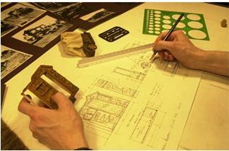
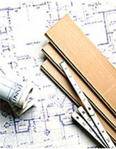
4 Working Drawings The final stage of illustrating your solution is to prepare a set of technical illustrations called Working Drawings. This set of drawings contains all the information needed to build the product.
5 Orthographic Drawings Used to show details of the front, top and right side views Uses 3 views Used to provide dimensions and special shapes by using different line types. For example object, hidden, and center lines. Draw the front first, top second, and right side last Space the views out equally at 40 mm A miter line is used to project details of the object from the top view to the right side view without measuring. Drawn at 45 degrees.
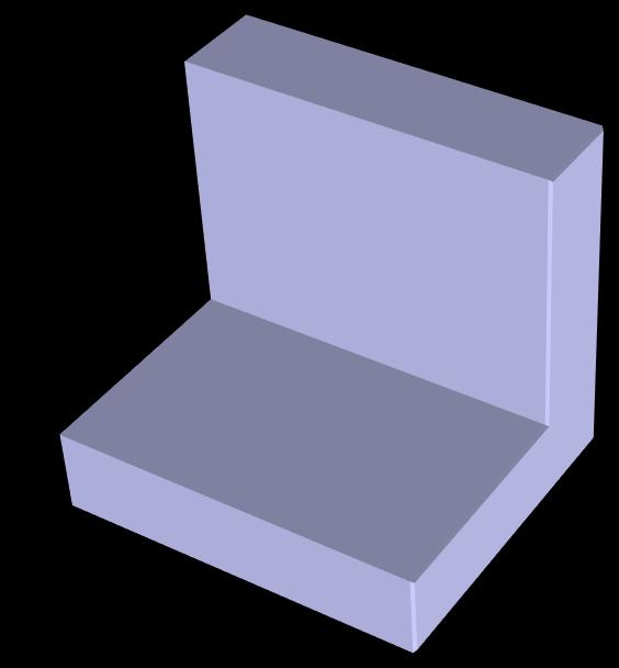
6 ISOMETRIC Drawings Three dimensional (3d) You can see how all three views fit together All horizontal lines are angled at 30 degrees and vertical lines remain vertical Hidden lines and dimensioning are not shown on Isometric drawings
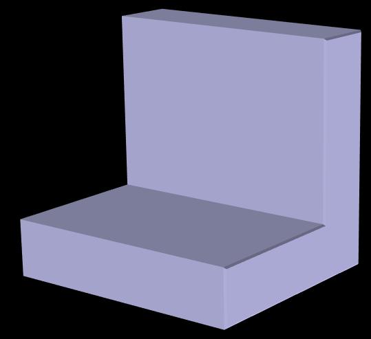
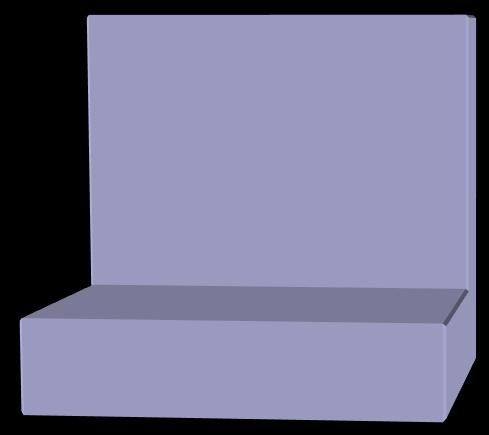
7 Orthographic and Isometric
8 Height Depth MULTIVIEW PROJECTION Three principle dimensions of an object can be presented only two in each view. Height Adjacent view(s) is needed to fulfill the size description. Width Depth Width Depth
9 TO OBTAIN MULTIVIEW REPRESENTATION OF AN OBJECT 1. Revolve the object with respect to observer. 2. The observer moves around the object.


10 REVOLVE THE OBJECT Top view Front view Right side view


11 OBSERVER MOVE AROUND Top view Front view Right side view
12 THE GLASS BOX CONCEPT Rear view Left side view Bottom view
13 Depth History Width Height


14 Orthographic Projection of Object Features
15 OBJECT FEATURES Edges Corners are lines that represent the boundary between two faces. Represent the intersection of two or more edges. Edge Edge No edge Corner No corner No corner
16 OBJECT FEATURES Surfaces Limiting element are areas that are bounded by edges or limiting element. is a line that represents the last visible part of the curve surface. Surface Surface Surface Limit Limit
17 PROJECTION OF LINE True length B T A T B T Equal length B A T A B R A F B F A R A F B F A R B R Point True length NORMAL LINE
18 PROJECTION OF LINE True length B T A T B T A B A T Equal length A F A B R B F A R A F B F A R B R Foreshortened Foreshortened INCLINED LINE
19 PROJECTION OF LINE Foreshortened B T A T B B T B F B R Equal length A T A B B F B R A F A A R A F A R Foreshortened Foreshortened OBLIQUED LINE
20 PROJECTION OF PLANE True size B T C T C T B A T C B T A T Equal length B F A C R A F,C F A R,B R B F A F,C F A R,B R C R Edge Edge NORMAL PLANE


21 PROJECTION OF PLANE Foreshortened C T B T C T A T C Equal length C F B C C R B T A T B F A C F C R A F A R,B R Foreshortened Edge B F A F A R,B R INCLINED PLANE
22 PROJECTION OF OBJECT The views are obtained by projecting all object features to the picture plane. You have to project the remaining surfaces which are invisible too!
23 PROJECTION OF OBJECT s s s
24 PROJECTION OF OBJECT
25 PROJECTION OF TOP VIEW
26 PROJECTION OF TOP VIEW
27 PROJECTION OF TOP VIEW
28 PROJECTION OF TOP VIEW
29 PROJECTION OF TOP VIEW
30 PROJECTION OF TOP VIEW
31 PROJECTION OF TOP VIEW
32 PROJECTION OF TOP VIEW
33 PROJECTION OF FRONT VIEW
34 PROJECTION OF FRONT VIEW
35 PROJECTION OF FRONT VIEW
36 PROJECTION OF FRONT VIEW
37 PROJECTION OF FRONT VIEW
38 PROJECTION OF FRONT VIEW
39 PROJECTION OF FRONT VIEW
40 PROJECTION OF FRONT VIEW
41 PROJECTION OF FRONT VIEW
42 PROJECTION OF RIGHT VIEW
43 PROJECTION OF RIGHT VIEW
44 PROJECTION OF RIGHT VIEW
45 PROJECTION OF RIGHT VIEW
46 PROJECTION OF RIGHT VIEW
47 PROJECTION OF RIGHT VIEW


48 Line Convention The meaning of lines
49 LINE CONVENTION The meaning of lines Precedence of coincide lines Hidden line drawing Center line drawing
50 THE MEANING OF LINES Object Lines
51 THE MEANING OF LINES Hidden Lines
52 THE MEANING OF LINES Center Lines Thin lines made up
53 THE MEANING OF LINES Dimension Lines
54 THE MEANING OF LINES Extension Lines


55 PRECEDENCE OF LINE Order of importance Visible line Hidden line Center line
56 OTHER ARCHITECTURAL LINES Hidden Lines

57 ARCHITECTURAL LINES Other Lines
58 OBJECT and HIDDEN LINE EXAMPLE
59 OBJECT, HIDDEN and CENTER LINE EXAMPLE Draw front view first
60 OBJECT, HIDDEN and CENTER LINE EXAMPLE Draw top view second
61 OBJECT, HIDDEN and CENTER LINE EXAMPLE Draw right side view last
62 HIDDEN LINE PRACTICE Hidden line should join a visible line, except it extended from the visible line. Leave space Join Correct No!
63 HIDDEN LINE PRACTICE Hidden line should join a visible line, except it extended from the visible line. Leave space Leave space Correct No!
64 HIDDEN LINE PRACTICE Hidden line should intersect to form L and T corners. L T Correct No!
65 HIDDEN LINE PRACTICE Hidden arcs should start on a center line.
66 HIDDEN LINE PRACTICE
67 HIDDEN LINE PRACTICE
68 HIDDEN LINE PRACTICE
69 HIDDEN LINE PRACTICE
70 HIDDEN LINE PRACTICE
71 HIDDEN LINE PRACTICE
72 HIDDEN LINE PRACTICE
73 HIDDEN LINE PRACTICE
74 CENTER LINE PRACTICE In circular view, short dash should cross at the intersections of center line. For small hole, center line is presented as thin continuous line. Center line should not extend between views. Leave space Leave space
75 CENTER LINE PRACTICE Leave the gap when centerline forms a continuation with a visible or hidden line Center line should always start and end with long dash. Leave space Leave space Leave space Leave space
76 DRAWING USING A MITER LINE
77 DRAWING USING A MITER LINE
78 DRAWING USING A MITER LINE
79 SCALED DRAWINGS Objects must be scaled to fit onto a piece of drawing paper They are exact in every detail but reduced or enlarged in size in direct proportion to the actual object Scale 1:1 1 mm on drawing paper = represents 1mm of the actual object
80 SCALED DRAWINGS Many objects are too large to be drawn to their full size. For example an airplane and house. Divide /
81 SCALED DRAWINGS Often it is necessary to produce drawings larger than full size Details of small objects are clearer and easier to dimension when they are drawn larger then their actual size Multiply X
82 TITLE BLOCK A title block is a portion of a drawing that is set aside to give important information about the drawing. The drafter, the scale, the units, and your name You must frame your drawing to make it look professional. Draw a 1 cm border and a 1 cm high area for your title block A title block template can be found on the shared drive. Ask your teacher.
83 TITLE BLOCK TEMPLATE
84 DIMENSIONING DRAWINGS
85 DIMENSIONING DRAWINGS
86 DIMENSIONING DRAWINGS Ask your teacher for a list of dimensioning Rules Dimensioning lines must follow these rules
87 THE STAGE IS SET FOR YOU TO BECOME AN EXPERT TECHNICAL DRAWER Practice drawing worksheets can be found on the shared drive
Engineering Drawing Lecture 5 PROJECTION THEORY
 University of Palestine College of Engineering & Urban Planning First Level Engineering Drawing Lecture 5 PROJECTION THEORY Lecturer: Eng. Eman Al.Swaity Eng.Heba hamad PART 1 PROJECTION METHOD TOPICS
ORTHOGRAPHIC PROJECTIONS. Ms. Sicola
 ORTHOGRAPHIC PROJECTIONS Ms. Sicola Objectives List the six principal views of projection Sketch the top, front and right-side views of an object with normal, inclined, and oblique surfaces Objectives
Orthographic Projection
 Orthographic Projection Why Orthographic Projection is used in technical drawing Orthographic projection is a method of producing a number of separate two-dimensional inter-related views, which are mutually
Multiview Drawing. Definition: Graphical representation of a 3- dimensional object on one plane (sheet of paper) using two or more views.
 using two or more views.") Multiview Drawing Definition: Graphical representation of a 3- dimensional object on one plane (sheet of paper) using two or more views. Multiview Drawing Another name for multiview drawing is orthographic
Multiview Drawing Definition: Graphical representation of a 3- dimensional object on one plane (sheet of paper) using two or more views. Multiview Drawing Another name for multiview drawing is orthographic
ORTHOGRAPHIC PROJECTION
 ORTHOGRAPHIC PROJECTION C H A P T E R S I X OBJECTIVES 1. Recognize and the symbol for third-angle projection. 2. List the six principal views of projection. 3. Understand which views show depth in a drawing
Multiviews and Auxiliary Views
 Multiviews and Auxiliary Views Multiviews and Auxiliary Views Objectives Explain orthographic and multiview projection. Identifying the six principal views. Apply standard line practices to multiviews
Student Name: Teacher: Date: District: Rowan. Assessment: 9_12 T and I IC61 - Drafting I Test 1. Description: Unit C - Sketching - Test 2.
 Student Name: Teacher: Date: District: Rowan Assessment: 9_12 T and I IC61 - Drafting I Test 1 Description: Unit C - Sketching - Test 2 Form: 501 1. The most often used combination of views includes the:
CLASS views from detail on a grid paper. (use appropriate line types to show features) - Optional views. Turn in for grading on class 6 (06/04)
 - Optional views. Turn in for grading on class 6 (06/04)") CLASS 4 Review: - Projections - Orthographic projections Lab: - 3 views from detail on a grid paper. (use appropriate line types to show features) - Optional views. Turn in for grading on class 6 (06/04)
CLASS 4 Review: - Projections - Orthographic projections Lab: - 3 views from detail on a grid paper. (use appropriate line types to show features) - Optional views. Turn in for grading on class 6 (06/04)
Copyrighted Material. Copyrighted Material. Copyrighted. Copyrighted. Material
 Engineering Graphics ORTHOGRAPHIC PROJECTION People who work with drawings develop the ability to look at lines on paper or on a computer screen and "see" the shapes of the objects the lines represent.
UNIT 5a STANDARD ORTHOGRAPHIC VIEW DRAWINGS
 UNIT 5a STANDARD ORTHOGRAPHIC VIEW DRAWINGS 5.1 Introduction Orthographic views are 2D images of a 3D object obtained by viewing it from different orthogonal directions. Six principal views are possible
Multi-View Drawing Review
 Multi-View Drawing Review Sacramento City College EDT 300/ENGR 306 EDT 300 / ENGR 306 - Chapter 5 1 Objectives Identify and select the various views of an object. Determine the number of views needed to
Fundamentals of Drafting - Orthographic Projection with Hidden Details
 Fundamentals of Drafting - Orthographic Projection with Hidden Details Objectives: 1. To extend the principle of orthographic projection for hidden details. 2. To illustrate the representation of hidden
Engineering Graphics, Class 8 Orthographic Projection. Mohammad I. Kilani. Mechanical Engineering Department University of Jordan
 Engineering Graphics, Class 8 Orthographic Projection Mohammad I. Kilani Mechanical Engineering Department University of Jordan Multi view drawings Multi view drawings provide accurate shape descriptions
Interpretation of Drawings. An Introduction to the Basic Concepts of Creating Technical Drawings
 Interpretation of Drawings An Introduction to the Basic Concepts of Creating Technical Drawings Introduction In the design process drawings are the main way in which information about an object or product
Multiview Projection
 DFTG-1305 Technical Drafting Prof. Francis Ha Session 4 Multiview Projection (or Orthographic Projection) Reading: Geisecke s textbook: 14 th Ed. Chapter 5 p.162 15 th Ed. Chapter 6 p.232 Update: 17-0510
MULTIPLE CHOICE QUESTIONS - CHAPTER 6
 MULTIPLE CHOICE QUESTIONS - CHAPTER 6 1. The selection of the front view in executing a multiview drawing of an object is dependent upon the following factors: a. size and shape of the object and their
ME 111: Engineering Drawing
 ME 111: Engineering Drawing Lecture 5 12-08-2011 Orthographic projection and Projection of Points Indian Institute of Technology Guwahati Guwahati 781039 1 Orthographic Projection A parallel projection
11/12/2015 CHAPTER 7. Axonometric Drawings (cont.) Axonometric Drawings (cont.) Isometric Projections (cont.) 1) Axonometric Drawings
 Axonometric Drawings (cont.) Isometric Projections (cont.) 1) Axonometric Drawings") CHAPTER 7 1) Axonometric Drawings 1) Introduction Isometric & Oblique Projection Axonometric projection is a parallel projection technique used to create a pictorial drawing of an object by rotating the
CHAPTER 7 1) Axonometric Drawings 1) Introduction Isometric & Oblique Projection Axonometric projection is a parallel projection technique used to create a pictorial drawing of an object by rotating the
ENGR 1182 Exam 1 First Mid Term Exam Study Guide and Practice Problems
 Spring Semester 2016 ENGR 1182 Exam 1 First Mid Term Exam Study Guide and Practice Problems Disclaimer Problems in this study guide resemble problems relating mainly to the pertinent homework assignments.
Lecture #4 MULTIVIEW PROJECTION RES 112E COMPUTER AIDED TECHNICAL DRAWING ITU
 Lecture #4 MULTIVIEW PROJECTION This week You will learn multi-view projection. The steps to follow are: Projections (ISO-E & ISO-A) Multi-view drawings Views (Basic,Auxiliary, Detailed etc.) Sketching
DFTG-1305 Technical Drafting Prof. Francis Ha
 DFTG-1305 Technical Drafting Prof. Francis Ha Session 4 Orthographic Projection (or Multiview Projection) Reading: Geisecke s textbook: 14 th Ed. Chapter 5 p.162 15 th Ed. Chapter 6 p.232 Update: 18-0205
Chapter 8. Technical Drawings
 Chapter 8 Technical Drawing Technical Drawings Multiview drawings Also called three-view drawings Simple objects take three views Front, top, one side Title block Identifies who did the design Gives date,
Graphical Communication
 Chapter 9 Graphical Communication mmm Becoming a fully competent engineer is a long yet rewarding process that requires the acquisition of many diverse skills and a wide body of knowledge. Learning most
ENGINEERING GRAPHICS 1E9
 Lecture 3 Monday, 15 December 2014 1 ENGINEERING GRAPHICS 1E9 Lecture 3: Isometric Projections Lecture 3 Monday, 15 December 2014 2 What is ISOMETRIC? It is a method of producing pictorial view of an object
ME1105 Engineering Drawing & Design
 City University London Term 1 Assessment 2008/2009 School of Engineering and Mathematical Sciences ME1105 Engineering Drawing & Design Student Name:.., Group: Examination duration: Reading time: This paper
Glass Box Projection. Gives you 6 sides to view of an object. 10/2/14 2
 2D Drawings Glass Box Projection Gives you 6 sides to view of an object. 10/2/14 2 We can simplify this for some objects to 3 views Glass Box Approach Glass Box Approach Glass Box Approach Glass Box Approach
Study Unit. Auxiliary Views. This sneak preview of your study material has been prepared in advance of the book's actual online release.
 Study Unit Auxiliary Views This sneak preview of your study material has been prepared in advance of the book's actual online release. iii Preview You re entering now into another subject area in your
ENGINEERING DRAWING SKKK 1021 ISOMETRIC DRAWING. Agus Arsad, Azizul Azri Bin Mustaffa 10/2/2012 1
 ENGINEERING DRAWING SKKK 1021 ISOMETRIC DRAWING Agus Arsad, Azizul Azri Bin Mustaffa 10/2/2012 1 LEARNING OUTCOMES ISOMETRIC DRAWING It is expected that students will be able to: Understand the significance
ENGINEERING GRAPHICS ESSENTIALS
 ENGINEERING GRAPHICS ESSENTIALS Text and Digital Learning KIRSTIE PLANTENBERG FIFTH EDITION SDC P U B L I C AT I O N S Better Textbooks. Lower Prices. www.sdcpublications.com ACCESS CODE UNIQUE CODE INSIDE
At the conclusion of this unit you should be able to accomplish the following with a 70% accuracy
 7 Multiview Drawing OBJECTIVES At the conclusion of this unit you should be able to accomplish the following with a 70% accuracy 1. explain the importance of mulitview drawing as a communication tool far
I B.TECH- I SEMESTER DEPARTMENT OF MECHANICAL ENGINEERING ENGINEERING DRAWING
 I B.TECH- I SEMESTER DEPARTMENT OF MECHANICAL ENGINEERING ENGINEERING DRAWING ENGINEERING DRAWING UNIT-V DEFINITIONS: Axonometric Trimetric Dimetric Isometric It is a parallel technique used to create
Describing an Angle Bracket
 Basics of Drafting Describing an Angle Bracket Orthographic Projection Orthographic drawings represent three dimensional objects in three separate views arranged in a standard manner. Orthographic Views
Guide To British Standards
 Guide To British Standards Higher Graphic Communication C O N T E N T S page TITLE BLOCK 2 DRAWING SCALES 2 LINE TYPES 3 ORTHOGRAPHIC PROJECTION 4 SECTIONAL VIEWS 4 SCREW THREADS & COMPONENTS 7 INTERUPTTED
A Concise Introduction to Engineering Graphics
 Concise Introduction to Engineering Graphics ourth Edition Including Worksheet Series imothy J. Sexton, Professor Department of Industrial echnology Ohio University ONUS ook on CD: ECHNICL GRPHICS Meyers,
Orthographic Drawing (Architectural Board Drafting)
") Design and Drafting Description In this activity, the teacher will introduce orthographic projection, in which a multi-view drawing shows how the sides of an object are related to each another. Students
Design and Drafting Description In this activity, the teacher will introduce orthographic projection, in which a multi-view drawing shows how the sides of an object are related to each another. Students
Chapter 1 Overview of an Engineering Drawing
 Chapter 1 Overview of an Engineering Drawing TOPICS Graphics language Engineering drawing Projection methods Orthographic projection Drawing standards TOPICS Traditional Drawing Tools Lettering Freehand
CHAPTER 01 PRESENTATION OF TECHNICAL DRAWING. Prepared by: Sio Sreymean
 CHAPTER 01 PRESENTATION OF TECHNICAL DRAWING Prepared by: Sio Sreymean 2015-2016 Why do we need to study this subject? Effectiveness of Graphics Language 1. Try to write a description of this object. 2.
ENGINEERING COMMUNICATIONS. Student Number:.
 The University of Melbourne Semester 2 Assessment, 1999 Department of Mechanical and Manufacturing Engineering 436-105 ENGINEERING COMMUNICATIONS Student Number:. Examination duration: Reading time: This
Mechanical Drawing. Unit 2 Study Guide for Chapters 6-10
 Mechanical Drawing Unit 2 Study Guide for Chapters 6-10 Chapter 6 Multiview Drawing Section 6.1 Understanding Orthographic Projection A. Technical Drawing: How can a technical drawing give more accurate
Drawing Types & Construction Drawings
 Drawing Types & Construction Drawings Building projects require several types of specialised drawings. This collection of drawings, known as a project set, includes: Location Plan Site Plan Floor Plan
PROJECTIONS PARALLEL CONICAL PROJECTIONS PROJECTIONS OBLIQUE ORTHOGRAPHIC PROJECTIONS PROJECTIONS
 PROJECTIONS CONICAL PROJECTIONS PARALLEL PROJECTIONS OBLIQUE PROJECTIONS ORTHOGRAPHIC PROJECTIONS ISOMETRIC MULTI-VIEW an object; The Description of Forms Behind every drawing of an object is space relationship
Chapter 5 Pictorial sketching
 Chapter 5 Pictorial sketching Contents Freehand sketching techniques Pictorial projections - Axonometric - Oblique Isometric projection vs isometric sketch Isometric sketch from an orthographic views Isometric
Engineering Graphics Essentials with AutoCAD 2015 Instruction
 Kirstie Plantenberg Engineering Graphics Essentials with AutoCAD 2015 Instruction Text and Video Instruction Multimedia Disc SDC P U B L I C AT I O N S Better Textbooks. Lower Prices. www.sdcpublications.com
ENGINEERING GRAPHICS ESSENTIALS
 ENGINEERING GRAPHICS ESSENTIALS with AutoCAD 2012 Instruction Introduction to AutoCAD Engineering Graphics Principles Hand Sketching Text and Independent Learning CD Independent Learning CD: A Comprehensive
AUXILIARY VIEWS C H A P T E R N I N E
 AUXILIARY VIEWS C H A P T E R N I N E Giesecke, Hill, Spencer, Dygdon, Novak, Lockhart, Goodman 1 OBJECTIVES 1. Create an auxiliary view from orthographic views. 2. Draw folding lines or reference-plane
AutoCAD Tutor 2011 Support Docs
 AutoCAD Tutor 2011 Support Docs CHAPTER 1 CUSTOMIZING THE QUICK ACCESS TOOLBAR One of the advantages of the Quick Access Toolbar is the ability to display the AutoCAD commands that you frequently use.
Orthographic Projection 1
 Orthographic Projection 1 What Is Orthographic Projection? Basically it is a way a representing a 3D object on a piece of paper. This means we make the object becomes 2D. The difference between Orthographic
DWG 002. Blueprint Reading. Geometric Terminology Orthographic Projection. Instructor Guide
 DWG 002 Blueprint Reading Geometric Terminology Orthographic Projection Instructor Guide Introduction Module Purpose The purpose of the Blueprint Reading modules is to introduce students to production
technical drawing
 technical drawing school of art, design and architecture nust spring 2011 http://www.youtube.com/watch?v=q6mk9hpxwvo http://www.youtube.com/watch?v=bnu2gb7w4qs Objective abstraction - axonometric view
ISOMETRIC PROJECTION. Contents. Isometric Scale. Construction of Isometric Scale. Methods to draw isometric projections/isometric views
 ISOMETRIC PROJECTION Contents Introduction Principle of Isometric Projection Isometric Scale Construction of Isometric Scale Isometric View (Isometric Drawings) Methods to draw isometric projections/isometric
Auxiliary view KCEC1101
 Auxiliary view KCEC1101 Introduction There are times when one of the six principal views will not completely describe an object. This is especially true when there are inclined or oblique planes or features
1 ISOMETRIC PROJECTION SECTION I: INTRODUCTION TO ISOMETRIC PROJECTION
 1 ISOMETRIC PROJECTION SECTION I: INTRODUCTION TO ISOMETRIC PROJECTION Orthographic projection shows drawings of an object in a two-dimensional format, with views given in plan, elevation and end elevation
60 Most Important Engineering Drawing Questions
 1. If a client of yours is having difficulty visualizing a design, what type of drawing would be the easiest to understand? A. axonometric B. three-view orthographic C. one-view orthographic D. bimetric
GL5: Visualisation and reading drawings
 436-105 Engineering Communications GL5:1 GL5: Visualisation and reading drawings Being able to both: represent a 3D object in multiview drawings interpret a multiview drawing to visualise a 3D object is
Transform 3D objects on to a 2D plane using projections
 PROJECTIONS 1 Transform 3D objects on to a 2D plane using projections 2 types of projections Perspective Parallel In parallel projection, coordinate positions are transformed to the view plane along parallel
ME 111: Engineering Drawing
 ME 111: Engineering Drawing Lecture # 01 Introduction For more detail, visit http://shilloi.iitg.ernet.in/~psr/ Indian Institute of Technology Guwahati Guwahati 781039 1 Syllabus 1. Importance of engineering
Principles and Practice
 Principles and Practice An Integrated Approach to Engineering Graphics and AutoCAD 2011 Randy H. Shih Oregon Institute of Technology SDC PUBLICATIONS www.sdcpublications.com Schroff Development Corporation
(Ans:d) a. A0 b. A1 c. A2 d. A3. (Ans:b) (Ans:a) (Ans:d) (Ans:d)
 a. A0 b. A1 c. A2 d. A3. (Ans:b) (Ans:a) (Ans:d) (Ans:d)") Multiple Choice Questions (MCQ) on Engineering Drawing (Instruments) The mini drafter serves the purpose of everything except a. Scales b. Set square c. Protractor d. Compass (Ans:d) During operation,
Multiple Choice Questions (MCQ) on Engineering Drawing (Instruments) The mini drafter serves the purpose of everything except a. Scales b. Set square c. Protractor d. Compass (Ans:d) During operation,
Philadelphia University Faculty of Engineering Mechanical Engineering Department
 Philadelphia University Faculty of Engineering Mechanical Engineering Department Basics of Engineering Drawing Manual Done by:- Eng. Laith R.I. Batarseh Eng. Hanan Khamis 2017 1 Table of contents SUBJECT
ENGR 1182 Midterm Exam 1: Study Guide and Practice Problems
 ENGR 1182 Midterm Exam 1: Study Guide and Practice Problems Disclaimer Problems seen in this study guide may resemble problems relating mainly to the pertinent homework assignments. Reading this study
ENGINEERING DRAWING. 1. Set squares are used to draw different angles. What is the angel a formed by the 45⁰ set square? Give a brief answer.
 ENGINEERING DRAWING 1. Set squares are used to draw different angles. What is the angel a formed by the 45⁰ set square? Give a brief answer. 2. Which is the correct method of hatching a plane surface?
Brief Introduction to Engineering Graphics The use of drawings to convey information. Sketching freehand straight edge
 Brief Introduction to Engineering Graphics The use of drawings to convey information. Sketching freehand straight edge CAD drawings 2D drafting 3D model to 2D drawings 1 Different Graphical Representation
Add labels to the sides...
 Orthographic Drawings Orthographic Projection A projection on a plane, using lines perpendicular to the plane Graphic communications has many forms. Orthographics is one such form. It was developed as
Geometric dimensioning & tolerancing (Part 1) KCEC 1101
 KCEC 1101") Geometric dimensioning & tolerancing (Part 1) KCEC 1101 Introduction Before an object can be built, complete information about both the size and shape of the object must be available. The exact shape of
Geometric dimensioning & tolerancing (Part 1) KCEC 1101 Introduction Before an object can be built, complete information about both the size and shape of the object must be available. The exact shape of
Exploring 3D in Flash
 1 Exploring 3D in Flash We live in a three-dimensional world. Objects and spaces have width, height, and depth. Various specialized immersive technologies such as special helmets, gloves, and 3D monitors
DMT113 Engineering Drawing. Chapter 3 Stretch System
 DMT113 Engineering Drawing Chapter 3 Stretch System Contents Theory & Multiview Planes 6 Principle Views Multiview Sketching Technique & Perspective First & Third Angle Multiview Representations Theory
Activity Multiview Sketches
 Activity 1.2.4 Multiview Sketches Introduction It s a very common occurrence to see a product advertisement and think, I thought of an idea for something like that just a few months ago. People spend a
Activity Multiview Sketches
 Activity 1.2.4 Multiview Sketches Purpose It s a very common occurrence to see a product advertisement and think, I thought of an idea for something like that just a few months ago. People spend a lot
Beginning Engineering Graphics 3 rd Week Lecture Notes Instructor: Edward N. Locke Topic: The Coordinate System, Types of Drawings and Orthographic
 Beginning Engineering Graphics 3 rd Week Lecture Notes Instructor: Edward N. Locke Topic: The Coordinate System, Types of Drawings and Orthographic 1 st Subject: The Cartesian Coordinate System The Cartesian
CE 100 Civil Engineering Drawing Sessional (Lab Manual)
") CE 100 Civil Engineering Drawing Sessional (Lab Manual) Department of Civil Engineering Ahsanullah University of Science and Technology November, 2017 1 Preface This course is designed to provide civil
CE 100 Civil Engineering Drawing Sessional (Lab Manual) Department of Civil Engineering Ahsanullah University of Science and Technology November, 2017 1 Preface This course is designed to provide civil
This section will take you through the process of drawing an oblique block. Your entire part, in all views, should look like Figure 1.
 Oblique Block Preface This section will take you through the process of drawing an oblique block. Your entire part, in all views, should look like Figure 1. Figure 1 68 / 3D Scripted Drawings: Oblique
Chapter 1 Overview of a Technical Drawing
 Chapter 1 Overview of a Technical Drawing TOPICS Graphics language Engineering drawing Projection methods Orthographic projection Drawing standards TOPICS Traditional Drawing Tools Lettering Dimensioning
UNIT Lines and Symbols
 3 UNIT Lines and Symbols Various lines on a drawing have different meanings. They may appear solid, broken, thick, or thin. Each is designed to help the blueprint reader make an interpretation. The standards
ORTHOGRAPHIC PROJECTION
 ORTHOGRAPHIC PROJECTION INTRODUCTION Any object has three dimensions, that is, length, width and thickness. A projection is defined as a representation of an object on a two dimensional plane. The projections
Sketching in SciTech. What you need to know for graphic communication
 Sketching in SciTech What you need to know for graphic communication Sketching in your Logbook Use pencil Take up the WHOLE PAGE Label things 1. Proportion Each part of the sketch is the right size,
Activity 2.4 Multi-view Sketching
 Activity 2.4 Multi-view Sketching Introduction It s a very common occurrence to see a product advertisement and think, I thought of an idea for something like that just a few months ago. People spend a
ENGINEERING GRAPHICS 1.0 Introduction Engineering Graphics Drawing as an art Artist Graphic design Engineering graphics engineering drawing
 ENGINEERING GRAPHICS 1.0 Introduction Engineering is the profession in which the knowledge of mathematics and science gained by study, experience and practice is applied with good judgment to develop a
Assignment 12 CAD Mechanical Part 2
 Assignment 12 CAD Mechanical Part 2 Objectives In this assignment you will learn to apply the hidden lines, isometric snap, and ellipses commands along with commands previously learned.. General Hidden
GOVERNMENT POLYTECHNIC, VALSAD MECHANICAL ENGINEERING DEPARTMENT ASSIGNMENT SUB: MECHANICAL DRAFTING (C321901) TERM:172
 TERM:172") GOVERNMENT POLYTECHNIC, VALSAD MECHANICAL ENGINEERING DEPARTMENT ASSIGNMENT SUB: MECHANICAL DRAFTING (C321901) TERM:172 1) When all the dimension are placed above the dimension line, it is called (a) Aligned
GOVERNMENT POLYTECHNIC, VALSAD MECHANICAL ENGINEERING DEPARTMENT ASSIGNMENT SUB: MECHANICAL DRAFTING (C321901) TERM:172 1) When all the dimension are placed above the dimension line, it is called (a) Aligned
2018 Technical Drawing Specifications Resource A guide to support VCE Visual Communication Design Study Design
 2018 Technical Drawing Specifications Resource A guide to support VCE Visual Communication Design Study Design 2018 22 VICTORIAN CURRICULUM AND ASSESSMENT AUTHORITY 1 Contents A guide to support VCE Visual
Contents. Notes on the use of this publication
 Contents Preface xxiii Scope Notes on the use of this publication xxv xxvi 1 Layout of drawings 1 1.1 General 1 1.2 Drawing sheets 1 1.3 Title block 2 1.4 Borders and frames 2 1.5 Drawing formats 2 1.6
7/9/2009. Offset Tool. Offset Tool. Offsetting - Erasing the Original Object. Chapter 8 Construction Tools and Multiview Drawings
 Chapter 8 Construction Tools and Multiview Drawings Use the OFFSET tool to draw parallel lines and curves. Mark points on objects at equal lengths using the DIVIDE tool. Set designated increments on an
Engineering Graphics. Class 2 Drafting Instruments Mohammad Kilani
 Engineering Graphics Class 2 Drafting Instruments Mohammad Kilani Drafting Instruments A Design is as good as its instruments A engineering drawing is a highly stylized graphic representation of an idea.
Engineering Working Drawings Basics
 Engineering Working Drawings Basics Engineering graphics is an effective way of communicating technical ideas and it is an essential tool in engineering design where most of the design process is graphically
2010 Academic Challenge
 2010 Academic Challenge ENGINEERING GRAPHICS TEST STATE FINALS This Test Consists of 40 Questions Engineering Graphics Test Production Team Ryan K. Brown, Illinois State University Author/Team Leader Jacob
Orthographic Projection
 ENG3000 Orthographic Projection 1 Session Objectives To understand the basic principles of orthographic projection To be able to construct orthographic views of simple objects To visualize 3 D objects
Drawing sheet: - The various size of the drawing sheet used for engineering drawing as per IS Are listed in the table
 Dronacharya Group of Institutions, Greater Noida Computer Aided Engineering Graphics (CAEG) (NCE 151/251) List of Drawing Sheets: 1. Letter writing & Dimensioning. 2. Projection of Points & Lines. 3. Projection
Student Name: Teacher: Date: District: Rowan. Assessment: 9_12 T and I IC61 - Drafting I Test 2. Description: Drafting 1 - Test 6.
 Student Name: Teacher: Date: District: Rowan Assessment: 9_12 T and I IC61 - Drafting I Test 2 Description: Drafting 1 - Test 6 Form: 501 1. 2X on a hole note means: A. Double the size of the hole. B.
2003 Academic Challenge
 Worldwide Youth in Science and Engineering 2003 Academic Challenge ENGINEERING GRAPHICS TEST - REGIONAL Engineering Graphics Test Production Team Ryan Brown, Illinois State University Author/Team Coordinator
Aircraft Drawing and Blueprint Reading
 Aircraft Drawing and Blueprint Reading Course Introduction Types of drawings Engineering also known as production or working drawings. Block diagram Types of Drawings Schematics Sketches Charts and graphs
Contents. Foreword. Using this Guide
 Foreword xv Preface xvii Scope Using this Guide xix xix 1 Specifying technical products 1 1.1 What is meant by technical product specification? 1 1.2 Design brief 1 1.3 Function 1 1.4 Specifications 2
2004 Academic Challenge
 2004 Academic Challenge ENGINEERING GRAPHICS TEST - REGIONAL Engineering Graphics Test Production Team Ryan Brown, Illinois State University Author/Team Coordinator Kevin Devine, Illinois State University
Page 1 of 5. ENGINEERING SKETCHES INFORMATION SHEETS MEL02INF2430 v1.1 HEALTH & SAFETY REQUIREMENTS
 Page 1 of 5 Competenz - N Z Engineering Food & Manufacturing Industry Training Organisation Inc. ENGINEERING SKETCHES INFORMATION SHEETS MEL02INF2430 v1.1 HEALTH & SAFETY REQUIREMENTS RECORDING REQUIREMENTS:
Civil Engineering Drawing
 Civil Engineering Drawing Third Angle Projection In third angle projection, front view is always drawn at the bottom, top view just above the front view, and end view, is drawn on that side of the front
Engineering Graphics, Class 13 Descriptive Geometry. Mohammad I. Kilani. Mechanical Engineering Department University of Jordan
 Engineering Graphics, Class 13 Descriptive Geometry Mohammad I. Kilani Mechanical Engineering Department University of Jordan Projecting a line into other views Given the front and right side projections
Fundamentals for building Drawing
 Fundamentals for building Drawing What is Drawing Introduction Knowledge of preparing and understanding drawing will prove to be an invaluable aid while performing their jobs effectively, efficiently.
ME 113 Computer Aided Engineering Drawing
 ME 113 Computer Aided Engineering Drawing Orthographic Projection - Visualizing Solids and Multiview Drawings Asst.Prof.Dr.Turgut AKYÜREK Çankaya University, Ankara Visualizing Solids and Multiview Drawings
Production drawing Diagram. a) I am a freehand drawing that follows technical drawing standards.
 I am a freehand drawing that follows technical drawing standards.") THE TECHNOLOGICAL WORLD Graphical language STUDENT BOOK Ch. 11, pp. 336 342 Basic lines, geometric lines, sketches 1. In technology, the two most widely used types of technical drawings are: a) sketch
THE TECHNOLOGICAL WORLD Graphical language STUDENT BOOK Ch. 11, pp. 336 342 Basic lines, geometric lines, sketches 1. In technology, the two most widely used types of technical drawings are: a) sketch
Change of position method:-
 Projections of Planes PROJECTIONS OF PLANES A plane is a two dimensional object having length and breadth only. Thickness is negligible. Types of planes 1. Perpendicular plane which have their surface