ME 111: Engineering Drawing
|
|
|
- Conrad Dickerson
- 6 years ago
- Views:
Transcription
1 ME 111: Engineering Drawing Lecture Orthographic projection and Projection of Points Indian Institute of Technology Guwahati Guwahati
2 Orthographic Projection A parallel projection technique in which the plane of projection is perpendicular to the parallel line of sight. Orthographic projection technique can produce either pictorial drawings that show all three dimensions of an object in one view, or multi-views that show only two dimensions of an object in a single view.
3
4


5 Multi-view Projection In an orthographic projection, the object is oriented in such a way that only two of its dimensions are shown. The dimensions obtained are the true dimensions of the object


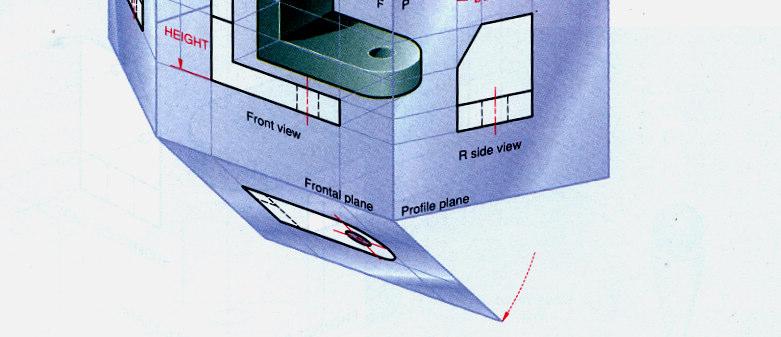
6 Frontal plane of projection Frontal plane of projection is the plane onto which the Front View (FV) of the multi-view drawing is projected. Front view of an object shows the width and height dimensions.

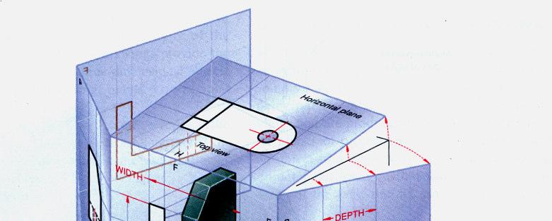
7 Horizontal plane of projection Horizontal plane of projection is the plane onto which the Top View of the multi-view drawing is projected. Top view of an object shows the width and depth dimensions. Dr P. S. Robi IIT Guwahati

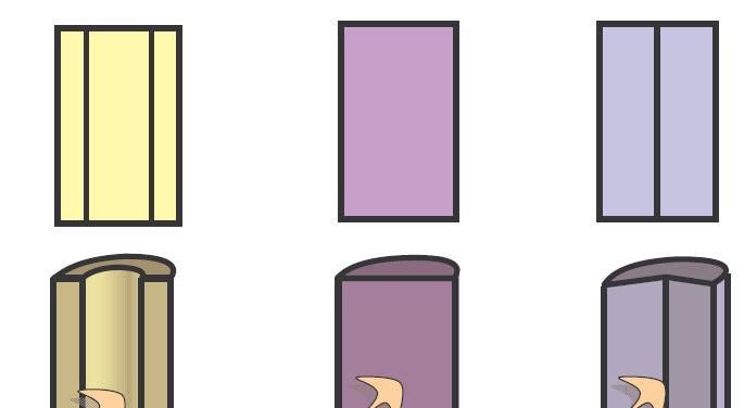
8 Profile plane of projection In multi-view drawings, the right side view is the standard side view used. The right side view of an object shows the depth and the height dimensions. The right side view is projected onto the profile plane of projection, which is a plane that is parallel to the right side of the object.

9 Orientation of views from projection planes Top view is always positioned and aligned with the front view, and side view is always positioned to the side of and aligned with the front view.
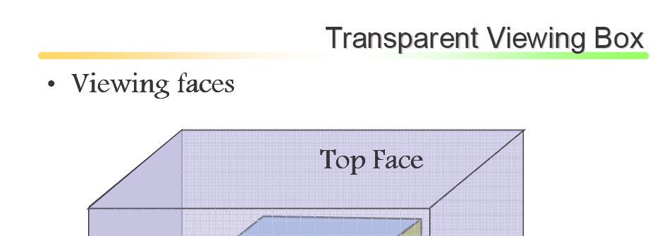
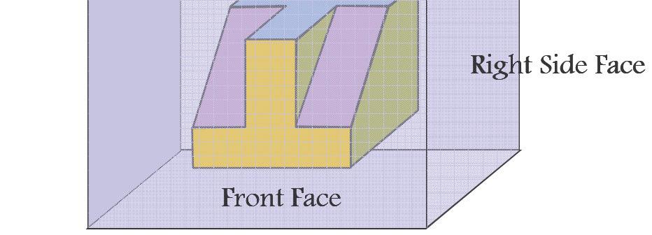
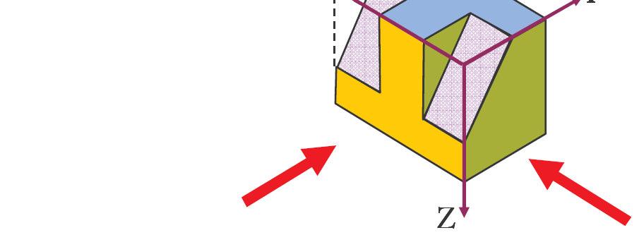
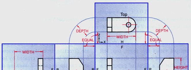
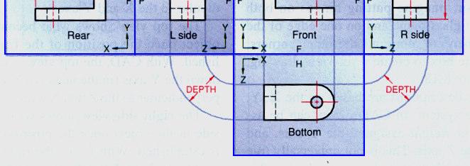
10 Six Principal views The plane of projection can be oriented to produce an infinite number of views of an object. However, some views are more important than others. These principal views are six mutually perpendicular views that are produced by six mutually perpendicular planes of projection. Imagine suspending an object in a glass box with major surfaces of the object positioned so that they are parallel to the sides of the box, six sides of the box become projection planes, showing the six views front, top, left, right, bottom and rear.
11 Six Principal Views Object is suspended in a glass producing box six principal views: each view is perpendicular to and aligned with the views. adjacent


12 Unfolding the glass box to produce sixview drawing Top, front and bottom views are all aligned vertically and share the same width dimension. Rear, left side, front and right side views are all aligned horizontally and share the same height dimension.
13
14


15 Conventional view placement The three-view multiview drawing is the standard used in engineering and technology, because many times the other three principal views are mirror images and do not add to the knowledge about the object. The standard views used in a three-view drawing are the top, front and the right side views


16 The width dimensions are aligned between the front and top views, using vertical projection lines. The height dimensions are aligned between the front and the profile views, using horizontal projection lines. Because of the relative positioning of the three views, the depth dimension cannot be aligned using projection lines. Instead, the depth dimension is measured in either the top or right side view.


17 The principal projection planes and quadrants used to create firstand thirdangle projection drawings
18 Orthographic projection and Projection of points Indian Institute of Technology Guwahati Guwahati
19

20
21
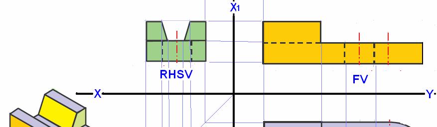
22 TV X1 Example X Y 1. Visible 2. Hidden 3. Center FV Y1 RHSV
23 Conventions
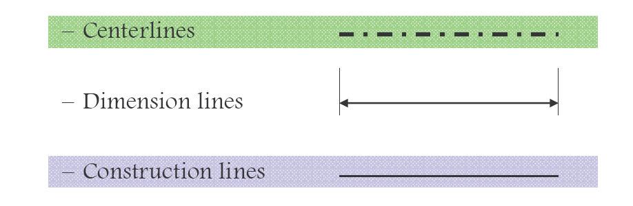
24 Convention Projectors and the lines of the intersection of planes of projections are shown as thin lines.
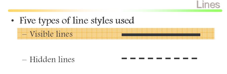
25 Precedence of Lines Visible lines take precedence over all other lines 0.70 mm Hidden lines take precedence over center lines 0.35 mm Center lines have lowest precedence 0.35 mm

26 Example: Application of Precedence
27 Intersecting Lines in Orthographic Projections Solid Line Intersections Dashed Line Special Case Intersections
28 Intersection of hidden line
29
30 Projection of Points (Orthographic)


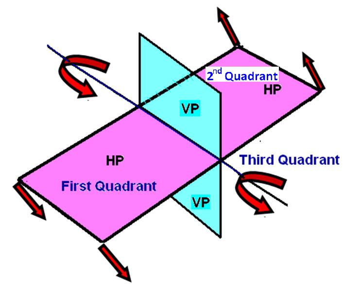
31 A POINT Define its position with respect to the coordinates. With respect to the VP, HP, & PP P P


32 Direction of rotation of the HP
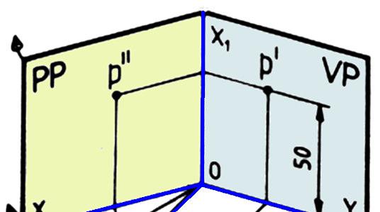
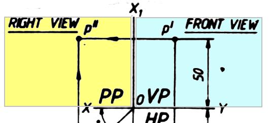
33 Convention Top views are represented by only small letters eg. a. Their front views are conventionally represented by small letters with dashes eg. a Profile or side views are represented by small letters with double dashes eg. a
34 Convention The line of intersection of HP and VP is denoted as XY. The line of intersection of VP and PP is denoted as X 1 Y 1
35 Convention Projectors and the lines of the intersection of planes of projections are shown as thin lines.


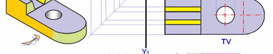
36 Point in the First quadrant Point P is 40 mm in front of VP, 50 mm above HP, 30 mm in front of left profile plane (PP)

37 Point in the First quadrant

38 Point in the First quadrant
39 Point in the First quadrant Procedure Draw a thin horizontal line, XY, to represent the line of intersection of HP and VP. Draw X1Y1 line to represent the line of intersection of VP and PP. Draw the Top View (p). Draw the projector line Draw the Front View (p) Y 1
40 Point in the First quadrant Procedure To project the right view on the left PP, draw a horizontal projector through p to intersect the 45 degree line at m. through m draw a vertical projector to intersect the horizontal projector drawn through p at p. p is the right view of point P
41 Happy Independence Day
Lecture 6 ( ): Theory of Multi-view Orthographic Projections
: Theory of Multi-view Orthographic Projections") Lecture 6 (06.08.12): Theory of Multi-view Orthographic Projections Dr. Sharad Gokhale Civil Engineering Department, IIT Guwahati 208, M-Block, Academic Complex Email: sharadbg@iitg.ernet.in Telephone
Lecture 6 (06.08.12): Theory of Multi-view Orthographic Projections Dr. Sharad Gokhale Civil Engineering Department, IIT Guwahati 208, M-Block, Academic Complex Email: sharadbg@iitg.ernet.in Telephone
ORTHOGRAPHIC PROJECTION
 ORTHOGRAPHIC PROJECTION INTRODUCTION Any object has three dimensions, that is, length, width and thickness. A projection is defined as a representation of an object on a two dimensional plane. The projections
Multiviews and Auxiliary Views
 Multiviews and Auxiliary Views Multiviews and Auxiliary Views Objectives Explain orthographic and multiview projection. Identifying the six principal views. Apply standard line practices to multiviews
ORTHOGRAPHIC PROJECTION
 ORTHOGRAPHIC PROJECTION C H A P T E R S I X OBJECTIVES 1. Recognize and the symbol for third-angle projection. 2. List the six principal views of projection. 3. Understand which views show depth in a drawing
CLASS views from detail on a grid paper. (use appropriate line types to show features) - Optional views. Turn in for grading on class 6 (06/04)
 - Optional views. Turn in for grading on class 6 (06/04)") CLASS 4 Review: - Projections - Orthographic projections Lab: - 3 views from detail on a grid paper. (use appropriate line types to show features) - Optional views. Turn in for grading on class 6 (06/04)
CLASS 4 Review: - Projections - Orthographic projections Lab: - 3 views from detail on a grid paper. (use appropriate line types to show features) - Optional views. Turn in for grading on class 6 (06/04)
ORTHOGRAPHIC PROJECTIONS. Ms. Sicola
 ORTHOGRAPHIC PROJECTIONS Ms. Sicola Objectives List the six principal views of projection Sketch the top, front and right-side views of an object with normal, inclined, and oblique surfaces Objectives
Multiview Drawing. Definition: Graphical representation of a 3- dimensional object on one plane (sheet of paper) using two or more views.
 using two or more views.") Multiview Drawing Definition: Graphical representation of a 3- dimensional object on one plane (sheet of paper) using two or more views. Multiview Drawing Another name for multiview drawing is orthographic
Multiview Drawing Definition: Graphical representation of a 3- dimensional object on one plane (sheet of paper) using two or more views. Multiview Drawing Another name for multiview drawing is orthographic
Orthographic Projection
 Orthographic Projection Why Orthographic Projection is used in technical drawing Orthographic projection is a method of producing a number of separate two-dimensional inter-related views, which are mutually
Auxiliary view KCEC1101
 Auxiliary view KCEC1101 Introduction There are times when one of the six principal views will not completely describe an object. This is especially true when there are inclined or oblique planes or features
Orthographic Projection
 ENG3000 Orthographic Projection 1 Session Objectives To understand the basic principles of orthographic projection To be able to construct orthographic views of simple objects To visualize 3 D objects
MULTIPLE CHOICE QUESTIONS - CHAPTER 6
 MULTIPLE CHOICE QUESTIONS - CHAPTER 6 1. The selection of the front view in executing a multiview drawing of an object is dependent upon the following factors: a. size and shape of the object and their
At the conclusion of this unit you should be able to accomplish the following with a 70% accuracy
 7 Multiview Drawing OBJECTIVES At the conclusion of this unit you should be able to accomplish the following with a 70% accuracy 1. explain the importance of mulitview drawing as a communication tool far
Glass Box Projection. Gives you 6 sides to view of an object. 10/2/14 2
 2D Drawings Glass Box Projection Gives you 6 sides to view of an object. 10/2/14 2 We can simplify this for some objects to 3 views Glass Box Approach Glass Box Approach Glass Box Approach Glass Box Approach
Technological Design Mr. Wadowski. Orthographic & Isometric Drawing Lesson
 Technological Design Mr. Wadowski Orthographic & Isometric Drawing Lesson TOPICS Working Drawings, Isometric Drawings & Orthographic Drawings Glass box concept Multiview projection Orthographic projection
PROJECTIONS PARALLEL CONICAL PROJECTIONS PROJECTIONS OBLIQUE ORTHOGRAPHIC PROJECTIONS PROJECTIONS
 PROJECTIONS CONICAL PROJECTIONS PARALLEL PROJECTIONS OBLIQUE PROJECTIONS ORTHOGRAPHIC PROJECTIONS ISOMETRIC MULTI-VIEW an object; The Description of Forms Behind every drawing of an object is space relationship
UNIT 5a STANDARD ORTHOGRAPHIC VIEW DRAWINGS
 UNIT 5a STANDARD ORTHOGRAPHIC VIEW DRAWINGS 5.1 Introduction Orthographic views are 2D images of a 3D object obtained by viewing it from different orthogonal directions. Six principal views are possible
DFTG-1305 Technical Drafting Prof. Francis Ha
 DFTG-1305 Technical Drafting Prof. Francis Ha Session 4 Orthographic Projection (or Multiview Projection) Reading: Geisecke s textbook: 14 th Ed. Chapter 5 p.162 15 th Ed. Chapter 6 p.232 Update: 18-0205
I B.TECH- I SEMESTER DEPARTMENT OF MECHANICAL ENGINEERING ENGINEERING DRAWING
 I B.TECH- I SEMESTER DEPARTMENT OF MECHANICAL ENGINEERING ENGINEERING DRAWING ENGINEERING DRAWING UNIT-V DEFINITIONS: Axonometric Trimetric Dimetric Isometric It is a parallel technique used to create
Multiview Projection
 DFTG-1305 Technical Drafting Prof. Francis Ha Session 4 Multiview Projection (or Orthographic Projection) Reading: Geisecke s textbook: 14 th Ed. Chapter 5 p.162 15 th Ed. Chapter 6 p.232 Update: 17-0510
ENGINEERING GRAPHICS ESSENTIALS
 ENGINEERING GRAPHICS ESSENTIALS Text and Digital Learning KIRSTIE PLANTENBERG FIFTH EDITION SDC P U B L I C AT I O N S Better Textbooks. Lower Prices. www.sdcpublications.com ACCESS CODE UNIQUE CODE INSIDE
Sheet 5: Projection of Points
 Sheet 5: Projection of Points POSITIONS OF A POINT A point may be located in space in any one of the quadrants. It may also lie on any one of the reference planes or both the reference planes. There are
Multi-View Drawing Review
 Multi-View Drawing Review Sacramento City College EDT 300/ENGR 306 EDT 300 / ENGR 306 - Chapter 5 1 Objectives Identify and select the various views of an object. Determine the number of views needed to
Engineering Graphics Essentials with AutoCAD 2015 Instruction
 Kirstie Plantenberg Engineering Graphics Essentials with AutoCAD 2015 Instruction Text and Video Instruction Multimedia Disc SDC P U B L I C AT I O N S Better Textbooks. Lower Prices. www.sdcpublications.com
Engineering Graphics, Class 8 Orthographic Projection. Mohammad I. Kilani. Mechanical Engineering Department University of Jordan
 Engineering Graphics, Class 8 Orthographic Projection Mohammad I. Kilani Mechanical Engineering Department University of Jordan Multi view drawings Multi view drawings provide accurate shape descriptions
ENGINEERING GRAPHICS ESSENTIALS
 ENGINEERING GRAPHICS ESSENTIALS with AutoCAD 2012 Instruction Introduction to AutoCAD Engineering Graphics Principles Hand Sketching Text and Independent Learning CD Independent Learning CD: A Comprehensive
ENGINEERING DRAWING. 1. Set squares are used to draw different angles. What is the angel a formed by the 45⁰ set square? Give a brief answer.
 ENGINEERING DRAWING 1. Set squares are used to draw different angles. What is the angel a formed by the 45⁰ set square? Give a brief answer. 2. Which is the correct method of hatching a plane surface?
Engineering Drawing Lecture 5 PROJECTION THEORY
 University of Palestine College of Engineering & Urban Planning First Level Engineering Drawing Lecture 5 PROJECTION THEORY Lecturer: Eng. Eman Al.Swaity Eng.Heba hamad PART 1 PROJECTION METHOD TOPICS
Lecture #4 MULTIVIEW PROJECTION RES 112E COMPUTER AIDED TECHNICAL DRAWING ITU
 Lecture #4 MULTIVIEW PROJECTION This week You will learn multi-view projection. The steps to follow are: Projections (ISO-E & ISO-A) Multi-view drawings Views (Basic,Auxiliary, Detailed etc.) Sketching
ME1105 Engineering Drawing & Design
 City University London Term 1 Assessment 2008/2009 School of Engineering and Mathematical Sciences ME1105 Engineering Drawing & Design Student Name:.., Group: Examination duration: Reading time: This paper
Describing an Angle Bracket
 Basics of Drafting Describing an Angle Bracket Orthographic Projection Orthographic drawings represent three dimensional objects in three separate views arranged in a standard manner. Orthographic Views
Student Name: Teacher: Date: District: Rowan. Assessment: 9_12 T and I IC61 - Drafting I Test 1. Description: Unit C - Sketching - Test 2.
 Student Name: Teacher: Date: District: Rowan Assessment: 9_12 T and I IC61 - Drafting I Test 1 Description: Unit C - Sketching - Test 2 Form: 501 1. The most often used combination of views includes the:
DMT113 Engineering Drawing. Chapter 3 Stretch System
 DMT113 Engineering Drawing Chapter 3 Stretch System Contents Theory & Multiview Planes 6 Principle Views Multiview Sketching Technique & Perspective First & Third Angle Multiview Representations Theory
Civil Engineering Drawing
 Civil Engineering Drawing Third Angle Projection In third angle projection, front view is always drawn at the bottom, top view just above the front view, and end view, is drawn on that side of the front
GL5: Visualisation and reading drawings
 436-105 Engineering Communications GL5:1 GL5: Visualisation and reading drawings Being able to both: represent a 3D object in multiview drawings interpret a multiview drawing to visualise a 3D object is
Graphical Communication
 Chapter 9 Graphical Communication mmm Becoming a fully competent engineer is a long yet rewarding process that requires the acquisition of many diverse skills and a wide body of knowledge. Learning most
Engineering Graphics, Class 13 Descriptive Geometry. Mohammad I. Kilani. Mechanical Engineering Department University of Jordan
 Engineering Graphics, Class 13 Descriptive Geometry Mohammad I. Kilani Mechanical Engineering Department University of Jordan Projecting a line into other views Given the front and right side projections
SIMILARLY IN CASE OF TINY OBJECTS DIMENSIONS MUST BE INCREASED FOR ABOVE PURPOSE. HENCE THIS SCALE IS CALLED ENLARGING SCALE. FOR FULL SIZE SCALE R.
 DIMENSIONS OF LARGE OBJECTS MUST BE REDUCED TO ACCOMMODATE ON STANDARD SIZE DRAWING SHEET.THIS REDUCTION CREATES A SCALE OF THAT REDUCTION RATIO, WHICH IS GENERALLY A FRACTION.. SUCH A SCALE IS CALLED
Principles and Practice
 Principles and Practice An Integrated Approach to Engineering Graphics and AutoCAD 2011 Randy H. Shih Oregon Institute of Technology SDC PUBLICATIONS www.sdcpublications.com Schroff Development Corporation
Add labels to the sides...
 Orthographic Drawings Orthographic Projection A projection on a plane, using lines perpendicular to the plane Graphic communications has many forms. Orthographics is one such form. It was developed as
2. Line composed of closely and evenly spaced short dashes in a drawing represents
 1. Hidden lines are drawn as (a) dashed narrow lines (b) dashed wide lines (c) long-dashed dotted wide line (d) long-dashed double dotted wide line Ans: (a) 2. Line composed of closely and evenly spaced
Engineering Graphics- Basics.
 Engineering Graphics- Basics DRAWINGS: ( A Graphical Representation) The Fact about: If compared with Verbal or Written Description, Drawings offer far better idea about the Shape, Size & Appearance of
11/12/2015 CHAPTER 7. Axonometric Drawings (cont.) Axonometric Drawings (cont.) Isometric Projections (cont.) 1) Axonometric Drawings
 Axonometric Drawings (cont.) Isometric Projections (cont.) 1) Axonometric Drawings") CHAPTER 7 1) Axonometric Drawings 1) Introduction Isometric & Oblique Projection Axonometric projection is a parallel projection technique used to create a pictorial drawing of an object by rotating the
CHAPTER 7 1) Axonometric Drawings 1) Introduction Isometric & Oblique Projection Axonometric projection is a parallel projection technique used to create a pictorial drawing of an object by rotating the
Copyrighted Material. Copyrighted Material. Copyrighted. Copyrighted. Material
 Engineering Graphics ORTHOGRAPHIC PROJECTION People who work with drawings develop the ability to look at lines on paper or on a computer screen and "see" the shapes of the objects the lines represent.
Orthographic Projection 1
 Orthographic Projection 1 What Is Orthographic Projection? Basically it is a way a representing a 3D object on a piece of paper. This means we make the object becomes 2D. The difference between Orthographic
Solutions to Exercise problems
 Brief Overview on Projections of Planes: Solutions to Exercise problems By now, all of us must be aware that a plane is any D figure having an enclosed surface area. In our subject point of view, any closed
AUXILIARY VIEWS C H A P T E R N I N E
 AUXILIARY VIEWS C H A P T E R N I N E Giesecke, Hill, Spencer, Dygdon, Novak, Lockhart, Goodman 1 OBJECTIVES 1. Create an auxiliary view from orthographic views. 2. Draw folding lines or reference-plane
CE 100 Civil Engineering Drawing Sessional (Lab Manual)
") CE 100 Civil Engineering Drawing Sessional (Lab Manual) Department of Civil Engineering Ahsanullah University of Science and Technology November, 2017 1 Preface This course is designed to provide civil
CE 100 Civil Engineering Drawing Sessional (Lab Manual) Department of Civil Engineering Ahsanullah University of Science and Technology November, 2017 1 Preface This course is designed to provide civil
3. The dimensioning SYMBOLS for arcs and circles should be given:
 Draft Student Name: Teacher: District: Date: Wake County Test: 9_12 T and I IC61 - Drafting I Test 2 Description: 4.08 Dimensioning Form: 501 1. The MINIMUM amount of space between two, ADJACENT DIMENSION
Sketching in SciTech. What you need to know for graphic communication
 Sketching in SciTech What you need to know for graphic communication Sketching in your Logbook Use pencil Take up the WHOLE PAGE Label things 1. Proportion Each part of the sketch is the right size,
7/9/2009. Offset Tool. Offset Tool. Offsetting - Erasing the Original Object. Chapter 8 Construction Tools and Multiview Drawings
 Chapter 8 Construction Tools and Multiview Drawings Use the OFFSET tool to draw parallel lines and curves. Mark points on objects at equal lengths using the DIVIDE tool. Set designated increments on an
Orthographic Drawing (Architectural Board Drafting)
") Design and Drafting Description In this activity, the teacher will introduce orthographic projection, in which a multi-view drawing shows how the sides of an object are related to each another. Students
Design and Drafting Description In this activity, the teacher will introduce orthographic projection, in which a multi-view drawing shows how the sides of an object are related to each another. Students
Exploring 3D in Flash
 1 Exploring 3D in Flash We live in a three-dimensional world. Objects and spaces have width, height, and depth. Various specialized immersive technologies such as special helmets, gloves, and 3D monitors
Chapter 4 ORTHOGRAPHIC PROJECTION
 Chapter 4 ORTHOGRAPHIC PROJECTION 4.1 INTRODUCTION We, the human beings are gifted with power to think. The thoughts are to be shared. You will appreciate that different ways and means are available to
Second Semester Session Shri Ramdeobaba College of Engineering & Management, Nagpur. Department of Mechanical Engineering
 Second Semester Session- 2017-18 Shri Ramdeobaba College of Engineering & Management, Nagpur. Department of Mechanical Engineering Engineering Drawing Practical Problem Sheet Sheet No.:- 1. Scales and
TPCT s College of Engineering, Osmanabad. Laboratory Manual. Engineering Graphics. For. First Year Students. Manual Prepared by B. G.
 TPCT s College of Engineering, Osmanabad Laboratory Manual Engineering Graphics For First Year Students Manual Prepared by B. G. Kadam Author COE, Osmanabad TPCT s College of Engineering Solapur Road,
BVRIT HYDERABAD College of Engineering for Women Department of Basic Sciences and Humanities
 BVRIT HYDERABAD College of Engineering for Women Department of Basic Sciences and Humanities Hand Out Subject Name: Engineering Graphics Prepared by (Faculty(s) Name): Mr. M Gopikrishna, Asst.Professor,
Student Name: Teacher: Date: District: Rowan. Assessment: 9_12 T and I IC61 - Drafting I Test 2. Description: Drafting 1 - Test 6.
 Student Name: Teacher: Date: District: Rowan Assessment: 9_12 T and I IC61 - Drafting I Test 2 Description: Drafting 1 - Test 6 Form: 501 1. 2X on a hole note means: A. Double the size of the hole. B.
Unit-5 ISOMETRIC PROJECTION
 Unit-5 ISOMETRIC PROJECTION Importance Points in Isometric: 1. For drawing the isometric, the object must be viewed such that either the front -right or the left edges becomes nearest. 2. All vertical
Indian Institute of Technology Kanpur National Programme on Technology Enhanced Learning (NPTEL) Course Title Engineering Graphics
 Course Title Engineering Graphics") Indian Institute of Technology Kanpur National Programme on Technology Enhanced Learning (NPTEL) Course Title Engineering Graphics Lecture 15 Oblique Projections-Part-III by Prof. Nihar Ranjan Patre Department
Indian Institute of Technology Kanpur National Programme on Technology Enhanced Learning (NPTEL) Course Title Engineering Graphics Lecture 15 Oblique Projections-Part-III by Prof. Nihar Ranjan Patre Department
Reading. Angel. Chapter 5. Optional
 Projections Reading Angel. Chapter 5 Optional David F. Rogers and J. Alan Adams, Mathematical Elements for Computer Graphics, Second edition, McGraw-Hill, New York, 1990, Chapter 3. The 3D synthetic camera
Interpretation of Drawings. An Introduction to the Basic Concepts of Creating Technical Drawings
 Interpretation of Drawings An Introduction to the Basic Concepts of Creating Technical Drawings Introduction In the design process drawings are the main way in which information about an object or product
Change of position method:-
 Projections of Planes PROJECTIONS OF PLANES A plane is a two dimensional object having length and breadth only. Thickness is negligible. Types of planes 1. Perpendicular plane which have their surface
Chapter 5 SECTIONS OF SOLIDS 5.1 INTRODUCTION
 Chapter 5 SECTIONS OF SOLIDS 5.1 INTRODUCTION We have studied about the orthographic projections in which a 3 dimensional object is detailed in 2-dimension. These objects are simple. In engineering most
ENGR 1182 Exam 1 First Mid Term Exam Study Guide and Practice Problems
 Spring Semester 2016 ENGR 1182 Exam 1 First Mid Term Exam Study Guide and Practice Problems Disclaimer Problems in this study guide resemble problems relating mainly to the pertinent homework assignments.
Question. Question. Product Features The Vocabulary of Design Download from web site. CAD/Fab Orthographic Projection 4
 Orthographic Projection Question What is the name of the feature indicated? A. Countersink B. Counterbore C. Spotface D. Hole E. Stepped hole CAD/Fab Assemblies & Mobility 2 Question Product Features The
SIDDHARTH GROUP OF INSTITUTIONS :: PUTTUR
 SIDDHARTH GROUP OF INSTITUTIONS :: PUTTUR Siddharth Nagar, Narayanavanam Road 517583 QUESTION BANK Subject Code : Engineering Graphics& Design Course & Branch : B.Tech ALL Year & Sem : I B.Tech & I Sem
GOVERNMENT POLYTECHNIC, VALSAD MECHANICAL ENGINEERING DEPARTMENT ASSIGNMENT SUB: MECHANICAL DRAFTING (C321901) TERM:172
 TERM:172") GOVERNMENT POLYTECHNIC, VALSAD MECHANICAL ENGINEERING DEPARTMENT ASSIGNMENT SUB: MECHANICAL DRAFTING (C321901) TERM:172 1) When all the dimension are placed above the dimension line, it is called (a) Aligned
GOVERNMENT POLYTECHNIC, VALSAD MECHANICAL ENGINEERING DEPARTMENT ASSIGNMENT SUB: MECHANICAL DRAFTING (C321901) TERM:172 1) When all the dimension are placed above the dimension line, it is called (a) Aligned
Mechanical Drawing. Unit 2 Study Guide for Chapters 6-10
 Mechanical Drawing Unit 2 Study Guide for Chapters 6-10 Chapter 6 Multiview Drawing Section 6.1 Understanding Orthographic Projection A. Technical Drawing: How can a technical drawing give more accurate
Introduction to Computer Graphics (CS602) Lecture 19 Projections
 Lecture 19 Projections") Introduction to Computer Graphics (CS602) Lecture 19 Projections For centuries, artists, engineers, designers, drafters, and architects have been facing difficulties and constraints imposed by the problem
Introduction to Computer Graphics (CS602) Lecture 19 Projections For centuries, artists, engineers, designers, drafters, and architects have been facing difficulties and constraints imposed by the problem
Chapter 8. Technical Drawings
 Chapter 8 Technical Drawing Technical Drawings Multiview drawings Also called three-view drawings Simple objects take three views Front, top, one side Title block Identifies who did the design Gives date,
Develop an Interior perspective from a floor plan using 2 points. using orthographic projection techniques
 Develop an Interior perspective from a floor plan using 2 points using orthographic projection techniques Obtain a floor of the space to be drawn Digital or hand drawn plan Plan must be to scale Often
Transform 3D objects on to a 2D plane using projections
 PROJECTIONS 1 Transform 3D objects on to a 2D plane using projections 2 types of projections Perspective Parallel In parallel projection, coordinate positions are transformed to the view plane along parallel
ENGINEERING GRAPHICS 1E9
 Lecture 3 Monday, 15 December 2014 1 ENGINEERING GRAPHICS 1E9 Lecture 3: Isometric Projections Lecture 3 Monday, 15 December 2014 2 What is ISOMETRIC? It is a method of producing pictorial view of an object
(Ans:d) a. A0 b. A1 c. A2 d. A3. (Ans:b) (Ans:a) (Ans:d) (Ans:d)
 a. A0 b. A1 c. A2 d. A3. (Ans:b) (Ans:a) (Ans:d) (Ans:d)") Multiple Choice Questions (MCQ) on Engineering Drawing (Instruments) The mini drafter serves the purpose of everything except a. Scales b. Set square c. Protractor d. Compass (Ans:d) During operation,
Multiple Choice Questions (MCQ) on Engineering Drawing (Instruments) The mini drafter serves the purpose of everything except a. Scales b. Set square c. Protractor d. Compass (Ans:d) During operation,
ME 113 Computer Aided Engineering Drawing
 ME 113 Computer Aided Engineering Drawing Orthographic Projection - Visualizing Solids and Multiview Drawings Asst.Prof.Dr.Turgut AKYÜREK Çankaya University, Ankara Visualizing Solids and Multiview Drawings
Reading. Projections. The 3D synthetic camera model. Imaging with the synthetic camera. Angel. Chapter 5. Optional
 Reading Angel. Chapter 5 Optional Projections David F. Rogers and J. Alan Adams, Mathematical Elements for Computer Graphics, Second edition, McGraw-Hill, New York, 1990, Chapter 3. The 3D snthetic camera
ISOMETRIC PROJECTION. Contents. Isometric Scale. Construction of Isometric Scale. Methods to draw isometric projections/isometric views
 ISOMETRIC PROJECTION Contents Introduction Principle of Isometric Projection Isometric Scale Construction of Isometric Scale Isometric View (Isometric Drawings) Methods to draw isometric projections/isometric
Understanding Projection Systems
 Understanding Projection Systems A Point: A point has no dimensions, a theoretical location that has neither length, width nor height. A point shows an exact location in space. It is important to understand
DELHI TECHNOLOGICAL UNIVERSITY ENGINEERING GRAPHICS LAB MANUAL
 DELHI TECHNOLOGICAL UNIVERSITY ENGINEERING GRAPHICS LAB MANUAL NAME: - ROLL NO: - GROUP: - BRANCH: - GROUP TEACHER: Page 1 www.rooplalrana.com 1 GENERAL INSTRUCTIONS FOR ENGG. GRAPHICS LAB 1) Students
60 Most Important Engineering Drawing Questions
 1. If a client of yours is having difficulty visualizing a design, what type of drawing would be the easiest to understand? A. axonometric B. three-view orthographic C. one-view orthographic D. bimetric
Set No - 1 I B. Tech I Semester Regular/Supplementary Examinations Jan./Feb ENGINEERING DRAWING (EEE)
") Set No - 1 I B. Tech I Semester Regular/Supplementary Examinations Jan./Feb. - 2015 ENGINEERING DRAWING Time: 3 hours (EEE) Question Paper Consists of Part-A and Part-B Answering the question in Part-A
Set No - 1 I B. Tech I Semester Regular/Supplementary Examinations Jan./Feb. - 2015 ENGINEERING DRAWING Time: 3 hours (EEE) Question Paper Consists of Part-A and Part-B Answering the question in Part-A
ENGINEERING DRAWING. UNIT III - Part A
 DEVELOPMENT OF SURFACES: ENGINEERING DRAWING UNIT III - Part A 1. What is meant by development of surfaces? 2. Development of surfaces of an object is also known as flat pattern of the object. (True/ False)
ENGINEERING GRAPHICS UNIT V ISOMETRIC PROJECTION PERSPECTIVE PROJECTION
 ENGINEERING GRAPHICS UNIT V ISOMETRIC PROJECTION PERSPECTIVE PROJECTION 1.PICTORIAL PROJECTIONS To visualize the shape of the whole object in its 3- D form, all the two or three orthographic views of the
Drawing sheet: - The various size of the drawing sheet used for engineering drawing as per IS Are listed in the table
 Dronacharya Group of Institutions, Greater Noida Computer Aided Engineering Graphics (CAEG) (NCE 151/251) List of Drawing Sheets: 1. Letter writing & Dimensioning. 2. Projection of Points & Lines. 3. Projection
Beginning Engineering Graphics 3 rd Week Lecture Notes Instructor: Edward N. Locke Topic: The Coordinate System, Types of Drawings and Orthographic
 Beginning Engineering Graphics 3 rd Week Lecture Notes Instructor: Edward N. Locke Topic: The Coordinate System, Types of Drawings and Orthographic 1 st Subject: The Cartesian Coordinate System The Cartesian
Chapter 5 Pictorial sketching
 Chapter 5 Pictorial sketching Contents Freehand sketching techniques Pictorial projections - Axonometric - Oblique Isometric projection vs isometric sketch Isometric sketch from an orthographic views Isometric
Fundamentals of Drafting - Orthographic Projection with Hidden Details
 Fundamentals of Drafting - Orthographic Projection with Hidden Details Objectives: 1. To extend the principle of orthographic projection for hidden details. 2. To illustrate the representation of hidden
Engineering Graphics. Practical Book. Government Engineering College Bhuj (Kutch - Gujarat) Department of Mechanical Engineering
 Department of Mechanical Engineering") Engineering Graphics Practical Book ASHISH J. MODI Department of Mechanical Engineering Government Engineering College Bhuj 370 001 (Kutch - Gujarat) SYLLABUS (AS PER GUJARAT TECHNOLOGICAL UNIVERSITY,
Engineering Graphics Practical Book ASHISH J. MODI Department of Mechanical Engineering Government Engineering College Bhuj 370 001 (Kutch - Gujarat) SYLLABUS (AS PER GUJARAT TECHNOLOGICAL UNIVERSITY,
4. Draw the development of the lateral surface of the part P of the cylinder whose front view is shown in figure 4. All dimensions are in cm.
 Code No: Z0122 / R07 Set No. 1 I B.Tech - Regular Examinations, June 2009 ENGINEERING GRAPHICS ( Common to Civil Engineering, Mechanical Engineering, Chemical Engineering, Bio-Medical Engineering, Mechatronics,
Dimensioning in the figure below could be improved by: A
 1-Multiview-study Page 1 of 8 irections For Numbers 1-53 : Read each of the following multiple-choice items and the possible answers carefully. Mark the letter of the correct answer on your answer sheet
APJ ABDUL KALAM TECHNOLOGICAL UNIVERSITY SECOND SEMESTER B.TECH DEGREE EXAMINATION, MAY PART A Answer ANY Two questions. 10 marks each.
 B B2B111 Pages: 2 Reg. No. Name: SECOND SEMESTER B.TECH DEGREE EXAMINATION, MAY 2017 Max.Marks:50 Course Code: BE110 Duration:3Hours Answer ANY Two questions. 10 marks each. 1. A line AB 100 mm long and
Introduction to Projection The art of representing a three-dimensional object or scene in a 2D space is called projection.
 Introduction to Projection The art of representing a three-dimensional object or scene in a 2D space is called projection. Projection is carried out by passing projectors through each vertex and intersecting
CHAPTER 01 PRESENTATION OF TECHNICAL DRAWING. Prepared by: Sio Sreymean
 CHAPTER 01 PRESENTATION OF TECHNICAL DRAWING Prepared by: Sio Sreymean 2015-2016 Why do we need to study this subject? Effectiveness of Graphics Language 1. Try to write a description of this object. 2.
BHARATHIDASAN ENGINEERING COLLEGE MGR NAGAR, NATRAM PALLI. Department of Mechanical Engineering GE6152 ENGINEERING GRAPHICS NOTES
 BHARATHIDASAN ENGINEERING COLLEGE MGR NAGAR, NATRAM PALLI Department of Mechanical Engineering GE6152 ENGINEERING GRAPHICS NOTES GE6152 ENGINEERING GRAPHICS OBJECTIVES: concepts, ideas and design of Engineering
DWG 002. Blueprint Reading. Geometric Terminology Orthographic Projection. Instructor Guide
 DWG 002 Blueprint Reading Geometric Terminology Orthographic Projection Instructor Guide Introduction Module Purpose The purpose of the Blueprint Reading modules is to introduce students to production
Isometric Drawing Chapter 26
 Isometric Drawing Chapter 26 Sacramento City College EDT 310 EDT 310 - Chapter 26 - Isometric Drawing 1 Drawing Types Pictorial Drawing types: Perspective Orthographic Isometric Oblique Pictorial - like
GE ENGINEERING GRAPHICS
 ANNA UNIVERSITY, CHENNAI (REGULATION GE8152 - ENGINEERING GRAPHICS B.E SEMESTER I Lecture Tutorial Practical Marks Credits Total Hours 2 0 3 100 4 90 Mr.S.Gokul (Asst. Prof/Mech) Sri Eshwar College of
ENGINEERING DRAWING I
 INSTITUTE OF ENGINEERING DEPARTMENT OF MECHANICAL ENGINEERING ENGINEERING DRAWING I [TUTORIAL SHEETS] 1 CONTENTS Sheet No. 1: Technical Lettering 3 Sheet No. 2: Plane Geometrical Construction 5 Sheet No.
Class 9 Coordinate Geometry
 ID : in-9-coordinate-geometry [1] Class 9 Coordinate Geometry For more such worksheets visit www.edugain.com Answer the questions (1) Find the coordinates of the point shown in the picture. (2) Find the