ENGINEERING GRAPHICS UNIT V ISOMETRIC PROJECTION PERSPECTIVE PROJECTION
|
|
|
- Marilyn Fleming
- 5 years ago
- Views:
Transcription
1 ENGINEERING GRAPHICS UNIT V ISOMETRIC PROJECTION PERSPECTIVE PROJECTION
2 1.PICTORIAL PROJECTIONS To visualize the shape of the whole object in its 3- D form, all the two or three orthographic views of the object have to be read simultaneously and a conclusion is to be drawn mentally about its shape. Engineers often find that they must prepare pictorial drawings, showing three or more number of faces in one view to convey the technical information to technically lay persons. Pictorial drawings are obtained by projecting an object only on one plane of projection.
3 Types of Pictorial Projections 1. Isometric Projection: An Isometric Projection is a pictorial projection in which three dimensions of a solid are not only shown in one view, but also their dimensions can be measured from it directly. 2.Perspective Projection: It shows an object as it appears instead of its true shape and size.
4 2. PRINCIPLE OF ISOMETRIC PROJECTION What is Isometric Projection? Iso means equal Metric means measure Isometric Projection means a system of projection of equality of measure. Ex: Projection of a Cube, resting on HP on one of its corners with a solid diagonal (Solid Diagonal is an imaginary line joining one of the corners at the top and the diametrically opposite corner at the bottom) perpendicular to HP.
.")
5 ISOMETRIC SCALE Isometric Projection= True length(tl).82
6 DIFFERENCE BETWEEN ORTHOGRAPHIC, ISOMETERIC PROJECTIONS, ISOMETRIC VIEW
7 ISOMETRIC VIEW Isometric View (Isometric Drawing) 1. Draw to actual scale. 2. When lines are drawn parallel to isometric axes, the true lengths are laid off. Isometric Projection 1.Drawn to isometric scale. When lines are drawn parallel to isometric axes, the length are forshorened to 0.82 times the actural
8 ISOMETRIC PROJECTION OF SQUARE HORIZONTAL AND VERTICAL Draw the isometric projection of a square lamina of side 35mm when it is placed with its surface. (a) Vertical and (b) Horizontal Case (a): Square Vertical Note: In Isometric projection/view, draw the vertical lines vertical and the horizontal lines inclined at an angle of 30º to the horizontal Case (b): Square Horizontal Take one corner draw lines both side 30º

9 ISOMETRIC PROJECTION OF SQUARE VERTICAL AND HORIZONTAL
10 ISOMETRIC PROJECTION OF RECTANGLE - HORIZONTAL
11 Isometric Projection of Prism Draw the isometric projection of a square prism of sid of base 35mm and height 65mm when its axis is (i) vertical and (ii) horizontal. Case (i) Axis of the square prism is vertical Case (ii) Axis of the square prism is horizontal Note: In isometric projection/view, hidden lines are not generally shown.
12 Isometric Projection of Prism
13 ISOMETRIC PROJECTION OF PRISM
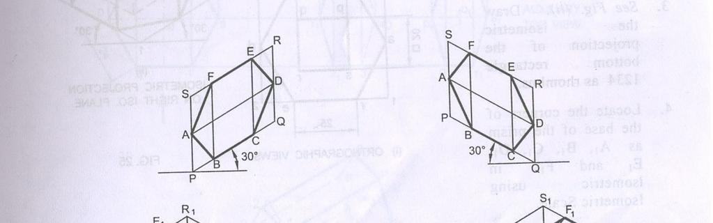
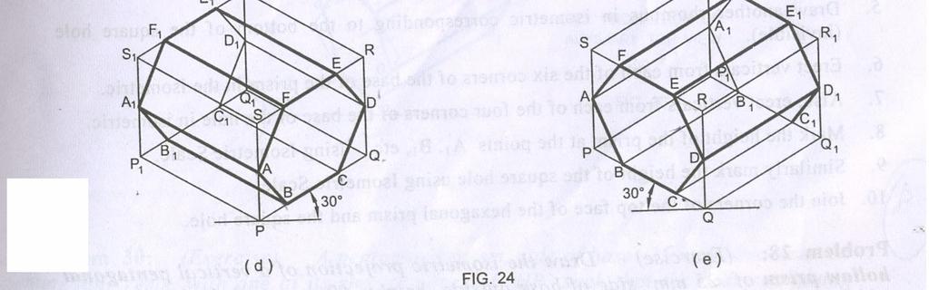
14 Isometric Projection of Prism Problem 25: Draw the three possible ways of representing the isometric projection of a hexagonal prism, side of base 25mm and height 60mm. RULE: Make direct measurements only on Isometric Lines. Lengths of edges cannot be transferred on Non-Isometric Lines. (e.g., B1 should not be marked on P1Q1 by cutting an arc on it with A1 as center and isometric length off (a1)(b1) as radius.

15 Isometric Projection of Prism
16 Isometric Projection of Prism
17 SECTIONED SOLIDS TRUNCATED AND FRUSTUM Problem 40: A pentagonal pyramid, base 30mm and axis 65mm long, rests with its base on HP. An edge of the base is parallel to VP and nearer to it. A horizontal section plane cuts the pyramid and passes through a point on the axis at a distance of 25mm from the apex. Draw the isometric projection of the frustum of the pyramid. (UQ)

18 Isometric Projection of Truncated Pyramid
19 Isometric Projection of Truncated Prism Problem 42: A hexagonal prism, side of base 25mm and height 50mm rests on HP and one of the edges of its base is parallel to VP. A section plane perpendicular to VP and inclined at 50º to HP bisects the axis of the prism. Draw the isometric projection of the truncated prism. Showing the cut surface.
20 Isometric Projection of Truncated Prism
21 Isometric Projection of Truncated Cylinder A cylinder 50mm diameter and 60mm height stands on HP. A section plane perpendicular to VP, inclined at 55º to HP cuts the cylinder and passes through a point on the axis at a height of 45mm above the base. Draw the isometric projection of the truncated portion of the cylinder, when the cut surface is clearly visible to the observer.

22 Isometric Projection of Truncated Cylinder
23 Isometric Projection of Truncated Pyramid Problem 46: A pentagonal pyramid, 30mm edge of base and 65mm height, stands on HP such that an edge of the base is parallel to VP and nearer to it. A section plane perpendicular to VP and inclined at 30º to HP cuts the pyramid passing through a point on the axis at a height of 35mm from the base. Draw the isometric projection of the truncated pyramid, showing the cut surface. (UQ)
24 Isometric Projection of Truncated Pyramid
25 PERSPECTIVE PROJECTION
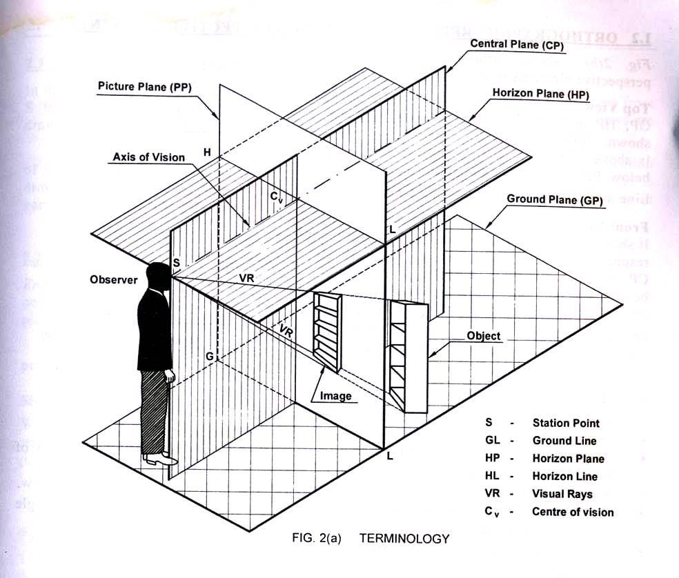
26 PRINCIPLE OF PERSPECTIVE PROJECTION Perspective projection of the graphic representation of an object on a single plane, as it appears to an observer, station a a particular position relative to the object. The plane is transparent and vertical and is called Picture Plane (PP). It is due to optical illusion. In perspective projection, the object is placed behind the PP. The observer is stationed in front of PP. Therefore, visual rays from the eyes of the observer to the object are cut by the PP, i.e., the rays pierce the picture plane and form an image on it. This image is the perspective view of the object. Visual rays locate the position of the object on the PP.
27 PERSPECTIVE PROJECTION
28 Third Angle Projection In perspective projection, PP is placed between the object and the eye. The arrangement of the eye, picture plane and the object is the same as in the case of Third Angle Projection. Therefore, the top view of the object is drawn above the front view.
29 Visual Ray Method In visual ray method, the top view and front view (or side view) of the object and position of the station point(sp) in both the views are located. Then visual rays from SP connecting various corners of the object in top and front views are drawn. The piercing points of these rays with picture plane are marked in top view and projected to front view to get perspective projection of the object.
30 Problems: Draw the perspective view of a square pyramid of base 30mm side and height of apex 45mm. The nearest edge of the base is parallel to and 20mm behind the picture plane. The station point is situated at a distance of 70mm in front of the PP and 40mm to the right of the axis of the pyramid and 60mm above the ground. A hexagonal pyramid of base side 25mm and axis length 50mm is resting on GP on its base with a side of base is parallel to and 20mm behind PP. The station point is 60mm of the pyramid. Drawing the perspective view of the pyramid.
31 PERSPECTIVE PROJECTION OF SOLIDS Problem 13: A square prism, side of base 40mm and height 60mm rests with its base on the ground such that on of its rectangular faces is parallel to and 10mm behind the picture plane. The station point is 30mm in front of PP, 80mm above the ground plane and lies in a central plane 45mm to the right of the center of the prism, Draw the perspective projection of the square prism
32 Visual Ray Method
33 A square prism of base 25 25mm and height 40mm rests on the GP on one of its ends with a rectangular face receding away from the PP towards right making 60 with PP. The corner nearest to the PP is 40mm to the left of the station point and 20mm behind the PP. The station point is 60mm above the GP and 50mm in front of the PP. Draw the perspective view of the prism by visual ray method. Use the top view and the front view. A cylinder of diameter 40mm and height 40mm rests on the GP on one of its ends with its axis 35mm behind the picture plane. The station point is 45mm to the right of the axis. The station point is 65mm above the GP and 40mm in front of the PP. Draw the perspective view of the cylinder by visual ray method.
34 Draw the perspective view of a pentagonal prism of base side 20mm and height 40mm when it rests on its base on the ground plane with one of its rectangular faces parallel to and 20mm behind the picture plane. The station point is 45mm in front of the PP and 60mm above the GP. The observer is 20mm to the left of the axis. Use the top view and the end view to draw the perspective by visual ray method. A cube of side 30mm is resting on a face on the ground such that one of its faces is parallel to PP and the centre of the solid is 5mm behind the PP. The central plane is located 30mm to the left of the nearest vertical face of cube the station point is 40mm in front of PP and 50mm above GP. Draw the perspective view of the solid.
35 Wish you a good luck
Unit-5 ISOMETRIC PROJECTION
 Unit-5 ISOMETRIC PROJECTION Importance Points in Isometric: 1. For drawing the isometric, the object must be viewed such that either the front -right or the left edges becomes nearest. 2. All vertical
GE 6152 ENGINEERING GRAPHICS
 GE 6152 ENGINEERING GRAPHICS UNIT - 4 DEVELOPMENT OF SURFACES Development of lateral surfaces of simple and truncated solids prisms, pyramids, cylinders and cones - Development of lateral surfaces of solids
APJ ABDUL KALAM TECHNOLOGICAL UNIVERSITY SECOND SEMESTER B.TECH DEGREE EXAMINATION, MAY PART A Answer ANY Two questions. 10 marks each.
 B B2B111 Pages: 2 Reg. No. Name: SECOND SEMESTER B.TECH DEGREE EXAMINATION, MAY 2017 Max.Marks:50 Course Code: BE110 Duration:3Hours Answer ANY Two questions. 10 marks each. 1. A line AB 100 mm long and
ENGINEERING DRAWING. UNIT III - Part A
 DEVELOPMENT OF SURFACES: ENGINEERING DRAWING UNIT III - Part A 1. What is meant by development of surfaces? 2. Development of surfaces of an object is also known as flat pattern of the object. (True/ False)
4. Draw the development of the lateral surface of the part P of the cylinder whose front view is shown in figure 4. All dimensions are in cm.
 Code No: Z0122 / R07 Set No. 1 I B.Tech - Regular Examinations, June 2009 ENGINEERING GRAPHICS ( Common to Civil Engineering, Mechanical Engineering, Chemical Engineering, Bio-Medical Engineering, Mechatronics,
I B.TECH- I SEMESTER DEPARTMENT OF MECHANICAL ENGINEERING ENGINEERING DRAWING
 I B.TECH- I SEMESTER DEPARTMENT OF MECHANICAL ENGINEERING ENGINEERING DRAWING ENGINEERING DRAWING UNIT-V DEFINITIONS: Axonometric Trimetric Dimetric Isometric It is a parallel technique used to create
ENGINEERING GRAPHICS 1E9
 Lecture 3 Monday, 15 December 2014 1 ENGINEERING GRAPHICS 1E9 Lecture 3: Isometric Projections Lecture 3 Monday, 15 December 2014 2 What is ISOMETRIC? It is a method of producing pictorial view of an object
SAMPLE QUESTION PAPER III ENGINEERING GRAPHICS (046) Time Allowed: 3 hours Maximum Marks: 70
 Time Allowed: 3 hours Maximum Marks: 70") SAMPLE QUESTION PAPER III ENGINEERING GRAPHICS (046) Time Allowed: 3 hours Maximum Marks: 70 Note: (i) Attempt all the questions. (ii) Use both sides of the drawing sheet, if necessary. (iii) All dimensions
SAMPLE QUESTION PAPER III ENGINEERING GRAPHICS (046) Time Allowed: 3 hours Maximum Marks: 70 Note: (i) Attempt all the questions. (ii) Use both sides of the drawing sheet, if necessary. (iii) All dimensions
ISOMETRIC PROJECTION. Contents. Isometric Scale. Construction of Isometric Scale. Methods to draw isometric projections/isometric views
 ISOMETRIC PROJECTION Contents Introduction Principle of Isometric Projection Isometric Scale Construction of Isometric Scale Isometric View (Isometric Drawings) Methods to draw isometric projections/isometric
6. Draw the isometric view of a cone 40 mm diameter and axis 55 mm long when its axis is horizontal. Draw isometric scale. [16]
![6. Draw the isometric view of a cone 40 mm diameter and axis 55 mm long when its axis is horizontal. Draw isometric scale. [16]](/thumbs/85/92603403.jpg "6. Draw the isometric view of a cone 40 mm diameter and axis 55 mm long when its axis is horizontal. Draw isometric scale. [16]") Code No: R05010107 Set No. 1 I B.Tech Supplimentary Examinations, Aug/Sep 2007 ENGINEERING GRAPHICS ( Common to Civil Engineering, Mechanical Engineering, Mechatronics, Metallurgy & Material Technology,
Code No: R05010107 Set No. 1 I B.Tech Supplimentary Examinations, Aug/Sep 2007 ENGINEERING GRAPHICS ( Common to Civil Engineering, Mechanical Engineering, Mechatronics, Metallurgy & Material Technology,
Change of position method:-
 Projections of Planes PROJECTIONS OF PLANES A plane is a two dimensional object having length and breadth only. Thickness is negligible. Types of planes 1. Perpendicular plane which have their surface
SIDDHARTH GROUP OF INSTITUTIONS :: PUTTUR
 SIDDHARTH GROUP OF INSTITUTIONS :: PUTTUR Siddharth Nagar, Narayanavanam Road 517583 QUESTION BANK Subject Code : Engineering Graphics& Design Course & Branch : B.Tech ALL Year & Sem : I B.Tech & I Sem
INSTITUTE OF AERONAUTICAL ENGINEERING
 Course Name Course Code Class Branch INSTITUTE OF AERONAUTICAL ENGINEERING Dundigal, Hyderabad - 500 043 MECHANICAL ENGINEERING TUTORIAL QUESTION BANK : ENGINEERING DRAWING : A10301 : I - B. Tech : Common
Second Semester Session Shri Ramdeobaba College of Engineering & Management, Nagpur. Department of Mechanical Engineering
 Second Semester Session- 2017-18 Shri Ramdeobaba College of Engineering & Management, Nagpur. Department of Mechanical Engineering Engineering Drawing Practical Problem Sheet Sheet No.:- 1. Scales and
ENGINEERING GRAPHICS
 ENGINEERING GRAPHICS CLASS - XII (046) DESIGN OF THE QUESTION PAPER Time : 3 Hrs Max. Marks : 70 The weightage of the distribution of marks over different contents of the question paper shall be as follows:
Chapter 5 SECTIONS OF SOLIDS 5.1 INTRODUCTION
 Chapter 5 SECTIONS OF SOLIDS 5.1 INTRODUCTION We have studied about the orthographic projections in which a 3 dimensional object is detailed in 2-dimension. These objects are simple. In engineering most
BOARD DIPLOMA EXAMINATION, (C 14) APRIL/MAY 2015 DECE FIRST YEAR EXAMINATION ENGINEERING DRAWING
 APRIL/MAY 2015 DECE FIRST YEAR EXAMINATION ENGINEERING DRAWING") C 14 CHPC/EC/PET 107 4037 BOARD DIPLOMA EXAMINATION, (C 14) APRIL/MAY 2015 DECE FIRST YEAR EXAMINATION ENGINEERING DRAWING Time : 3 hours ] [ Total Marks : 60 Instructions : (1) Answer all questions. PART
C 14 CHPC/EC/PET 107 4037 BOARD DIPLOMA EXAMINATION, (C 14) APRIL/MAY 2015 DECE FIRST YEAR EXAMINATION ENGINEERING DRAWING Time : 3 hours ] [ Total Marks : 60 Instructions : (1) Answer all questions. PART
E GRAPHICS ISOMETRIC PROJECTIONS S.RAMANATHAN ASST PROF MVSREC PH: CONCEPTS.
 E GRPHIS ISOMETRI PROJETIONS S.RMNTHN SST PROF MVSRE ONEPTS. Isometric projections are 3-D representation of objects. Since we deal mostly with solids which are 3-D objects, we use isometric projections
Drawing sheet: - The various size of the drawing sheet used for engineering drawing as per IS Are listed in the table
 Dronacharya Group of Institutions, Greater Noida Computer Aided Engineering Graphics (CAEG) (NCE 151/251) List of Drawing Sheets: 1. Letter writing & Dimensioning. 2. Projection of Points & Lines. 3. Projection
ENGINEERING GRAPHICS
 ENGINEERING GRAPHICS Course Structure Units Topics Marks Unit I Plane Geometry 16 1 Lines, angles and rectilinear figures 2 Circles and tangents 3 Special curves: ellipse, parabola, involute, cycloid.
SAMPLE QUESTION PAPER II ENGINEERING GRAPHICS (046)
") SAMPLE QUESTION PAPER II ENGINEERING GRAPHICS (046) Time Allowed: 3 hours Maximum Marks: 70 Note: (i) Attempt all the questions. (ii) Use both sides of the drawing sheet, if necessary. (iii) All dimensions
SAMPLE QUESTION PAPER II ENGINEERING GRAPHICS (046) Time Allowed: 3 hours Maximum Marks: 70 Note: (i) Attempt all the questions. (ii) Use both sides of the drawing sheet, if necessary. (iii) All dimensions
Chapter 4 ORTHOGRAPHIC PROJECTION
 Chapter 4 ORTHOGRAPHIC PROJECTION 4.1 INTRODUCTION We, the human beings are gifted with power to think. The thoughts are to be shared. You will appreciate that different ways and means are available to
GE ENGINEERING GRAPHICS
 ANNA UNIVERSITY, CHENNAI (REGULATION GE8152 - ENGINEERING GRAPHICS B.E SEMESTER I Lecture Tutorial Practical Marks Credits Total Hours 2 0 3 100 4 90 Mr.S.Gokul (Asst. Prof/Mech) Sri Eshwar College of
BHARATHIDASAN ENGINEERING COLLEGE MGR NAGAR, NATRAM PALLI. Department of Mechanical Engineering GE6152 ENGINEERING GRAPHICS NOTES
 BHARATHIDASAN ENGINEERING COLLEGE MGR NAGAR, NATRAM PALLI Department of Mechanical Engineering GE6152 ENGINEERING GRAPHICS NOTES GE6152 ENGINEERING GRAPHICS OBJECTIVES: concepts, ideas and design of Engineering
Engineering Graphics. Practical Book. Government Engineering College Bhuj (Kutch - Gujarat) Department of Mechanical Engineering
 Department of Mechanical Engineering") Engineering Graphics Practical Book ASHISH J. MODI Department of Mechanical Engineering Government Engineering College Bhuj 370 001 (Kutch - Gujarat) SYLLABUS (AS PER GUJARAT TECHNOLOGICAL UNIVERSITY,
Engineering Graphics Practical Book ASHISH J. MODI Department of Mechanical Engineering Government Engineering College Bhuj 370 001 (Kutch - Gujarat) SYLLABUS (AS PER GUJARAT TECHNOLOGICAL UNIVERSITY,
ENGINEERING DRAWING I
 INSTITUTE OF ENGINEERING DEPARTMENT OF MECHANICAL ENGINEERING ENGINEERING DRAWING I [TUTORIAL SHEETS] 1 CONTENTS Sheet No. 1: Technical Lettering 3 Sheet No. 2: Plane Geometrical Construction 5 Sheet No.
DELHI TECHNOLOGICAL UNIVERSITY ENGINEERING GRAPHICS LAB MANUAL
 DELHI TECHNOLOGICAL UNIVERSITY ENGINEERING GRAPHICS LAB MANUAL NAME: - ROLL NO: - GROUP: - BRANCH: - GROUP TEACHER: Page 1 www.rooplalrana.com 1 GENERAL INSTRUCTIONS FOR ENGG. GRAPHICS LAB 1) Students
ORTHOGRAPHIC PROJECTION
 ORTHOGRAPHIC PROJECTION INTRODUCTION Any object has three dimensions, that is, length, width and thickness. A projection is defined as a representation of an object on a two dimensional plane. The projections
ENGINEERING DRAWING. 1. Set squares are used to draw different angles. What is the angel a formed by the 45⁰ set square? Give a brief answer.
 ENGINEERING DRAWING 1. Set squares are used to draw different angles. What is the angel a formed by the 45⁰ set square? Give a brief answer. 2. Which is the correct method of hatching a plane surface?
ENGINEERING GRAPHICS CLASS - XII (046) DESIGN OF THE QUESTION PAPER
 DESIGN OF THE QUESTION PAPER") ENGINEERING GRAPHICS CLASS - XII (046) DESIGN OF THE QUESTION PAPER Time : 3 Hrs Max. Marks : 70 The weightage of the distribution of marks over different contents of the question paper shall be as follows:
ENGINEERING GRAPHICS CLASS - XII (046) DESIGN OF THE QUESTION PAPER Time : 3 Hrs Max. Marks : 70 The weightage of the distribution of marks over different contents of the question paper shall be as follows:
Isometric Drawing Chapter 26
 Isometric Drawing Chapter 26 Sacramento City College EDT 310 EDT 310 - Chapter 26 - Isometric Drawing 1 Drawing Types Pictorial Drawing types: Perspective Orthographic Isometric Oblique Pictorial - like
(Common to E&E /MECHATRONICS/ HPT/ WSM/TEXTILE /MINING/CERAMICS/AGRICULTURE ENGG./ AERONAUTICAL ENGG./LEATHER & FASHION TECHNOLOGY Programmes)
") Government of Karnataka Department of Technical Education Board of Technical Examinations, Bengaluru Course Title: ENGINEERING Course Code: 15ME01D DRAWING Semester : I / II Core/ Elective: Core Teaching
Government of Karnataka Department of Technical Education Board of Technical Examinations, Bengaluru Course Title: ENGINEERING Course Code: 15ME01D DRAWING Semester : I / II Core/ Elective: Core Teaching
Set No - 1 I B. Tech I Semester Regular/Supplementary Examinations Jan./Feb ENGINEERING DRAWING (EEE)
") Set No - 1 I B. Tech I Semester Regular/Supplementary Examinations Jan./Feb. - 2015 ENGINEERING DRAWING Time: 3 hours (EEE) Question Paper Consists of Part-A and Part-B Answering the question in Part-A
Set No - 1 I B. Tech I Semester Regular/Supplementary Examinations Jan./Feb. - 2015 ENGINEERING DRAWING Time: 3 hours (EEE) Question Paper Consists of Part-A and Part-B Answering the question in Part-A
BVRIT HYDERABAD College of Engineering for Women Department of Basic Sciences and Humanities
 BVRIT HYDERABAD College of Engineering for Women Department of Basic Sciences and Humanities Hand Out Subject Name: Engineering Graphics Prepared by (Faculty(s) Name): Mr. M Gopikrishna, Asst.Professor,
11/12/2015 CHAPTER 7. Axonometric Drawings (cont.) Axonometric Drawings (cont.) Isometric Projections (cont.) 1) Axonometric Drawings
 Axonometric Drawings (cont.) Isometric Projections (cont.) 1) Axonometric Drawings") CHAPTER 7 1) Axonometric Drawings 1) Introduction Isometric & Oblique Projection Axonometric projection is a parallel projection technique used to create a pictorial drawing of an object by rotating the
CHAPTER 7 1) Axonometric Drawings 1) Introduction Isometric & Oblique Projection Axonometric projection is a parallel projection technique used to create a pictorial drawing of an object by rotating the
GOVERNMENT POLYTECHNIC, VALSAD MECHANICAL ENGINEERING DEPARTMENT ASSIGNMENT SUB: MECHANICAL DRAFTING (C321901) TERM:172
 TERM:172") GOVERNMENT POLYTECHNIC, VALSAD MECHANICAL ENGINEERING DEPARTMENT ASSIGNMENT SUB: MECHANICAL DRAFTING (C321901) TERM:172 1) When all the dimension are placed above the dimension line, it is called (a) Aligned
GOVERNMENT POLYTECHNIC, VALSAD MECHANICAL ENGINEERING DEPARTMENT ASSIGNMENT SUB: MECHANICAL DRAFTING (C321901) TERM:172 1) When all the dimension are placed above the dimension line, it is called (a) Aligned
 6.1 INTRODUCTION Chapter 6 ORTHOGRAPHIC PROJECTIONS OF SIMPLE MACHINE BLOCKS We have already made you aware of many simple geometrical shapes (laminae), projected on such planes (vertical plane, horizontal
1 ISOMETRIC PROJECTION SECTION I: INTRODUCTION TO ISOMETRIC PROJECTION
 1 ISOMETRIC PROJECTION SECTION I: INTRODUCTION TO ISOMETRIC PROJECTION Orthographic projection shows drawings of an object in a two-dimensional format, with views given in plan, elevation and end elevation
Copyrighted Material. Copyrighted Material. Copyrighted. Copyrighted. Material
 Engineering Graphics ORTHOGRAPHIC PROJECTION People who work with drawings develop the ability to look at lines on paper or on a computer screen and "see" the shapes of the objects the lines represent.
Government of Karnataka Department of Technical Education Board of Technical Examinations, Bengaluru Course Title: ENGINEERING DRAWING-II
 Government of Karnataka Department of Technical Education Board of Technical Examinations, Bengaluru Course Title: ENGINEERING DRAWING-II Credits (L:T:P) : 0:2:4 Total Contact Hours: 78 Course Code: 15CE22D
Add labels to the sides...
 Orthographic Drawings Orthographic Projection A projection on a plane, using lines perpendicular to the plane Graphic communications has many forms. Orthographics is one such form. It was developed as
DMT113 Engineering Drawing. Chapter 3 Stretch System
 DMT113 Engineering Drawing Chapter 3 Stretch System Contents Theory & Multiview Planes 6 Principle Views Multiview Sketching Technique & Perspective First & Third Angle Multiview Representations Theory
ENGINEERING GRAPHICS (Code No. 046)
") ENGINEERING GRAPHICS (Code No. 046) CLASS XI-XII The subject of 'Engineering Graphics' has become an indispensable tool for Engineers, Technocrats, Architects, Draftsmen, Surveyors, Designers and many
ENGINEERING GRAPHICS (Code No. 046) CLASS XI-XII The subject of 'Engineering Graphics' has become an indispensable tool for Engineers, Technocrats, Architects, Draftsmen, Surveyors, Designers and many
ENGINEERING GRAPHICS
 ENGINEERING GRAPHICS Course Structure Parts/Units Topics Marks Unit - I Isometric Projection of Solids 25 Machine Drawing 45 Part A. Drawing of Machine Parts Unit - II Part B. Assembly Drawing and Dis-assembly
TPCT s College of Engineering, Osmanabad. Laboratory Manual. Engineering Graphics. For. First Year Students. Manual Prepared by B. G.
 TPCT s College of Engineering, Osmanabad Laboratory Manual Engineering Graphics For First Year Students Manual Prepared by B. G. Kadam Author COE, Osmanabad TPCT s College of Engineering Solapur Road,
Downloaded from ENGINEERING DRAWING. Time allowed : 3 hours Maximum Marks : 70
 ENGINEERING DRAWING Time allowed : 3 hours Maximum Marks : 70 Note : (i) (ii) Attempt all the questions. Use both sides of the drawing sheet, if necessary. (iii) All dimensions are in millimeters. (iv)
Trade of Metal Fabrication. Module 6: Fabrication Drawing Unit 13: Parallel Line Development Phase 2
 Trade of Metal Fabrication Module 6: Fabrication Drawing Unit 13: Parallel Line Development Phase 2 Table of Contents List of Figures... 4 List of Tables... 5 Document Release History... 6 Module 6 Fabrication
JUNIOR CERTIFICATE 2009 MARKING SCHEME TECHNICAL GRAPHICS HIGHER LEVEL
 . JUNIOR CERTIFICATE 2009 MARKING SCHEME TECHNICAL GRAPHICS HIGHER LEVEL Sections A and B Section A any ten questions from this section Q1 12 Four diagrams, 3 marks for each correct label. Q2 12 2 marks
ENGINEERING DRAWING
 Subject Code: R13109/R13 Set No - 1 I B. Tech I Semester Regular/Supplementary Examinations Jan./Feb. - 2015 ENGINEERING DRAWING (Common to ECE, EIE, Bio-Tech, EComE, Agri.E) Time: 3 hours Max. Marks:
ENGINEERING GRAPHICS (XI-XII) (Code No. 046)
 (Code No. 046)") ENGINEERING GRAPHICS (XI-XII) (Code No. 046) The subject of 'Engineering Graphics' has become an indispensable tool for Engineers, Technocrats, Architects, Draftsmen, Surveyors, Designers and many other
ENGINEERING GRAPHICS (XI-XII) (Code No. 046) The subject of 'Engineering Graphics' has become an indispensable tool for Engineers, Technocrats, Architects, Draftsmen, Surveyors, Designers and many other
Orthographic Projection 1
 Orthographic Projection 1 What Is Orthographic Projection? Basically it is a way a representing a 3D object on a piece of paper. This means we make the object becomes 2D. The difference between Orthographic
PESIT-BSC Department of Science & Humanities
 LESSON PLAN 15CED14/24 COMPUTER AIDED ENGINEERING DRAWING Course objectives: The Engineering drawing is an important tool for all Engineers and for many others professionals. It is the language of Engineers.
Orthographic Projection
 Orthographic Projection Why Orthographic Projection is used in technical drawing Orthographic projection is a method of producing a number of separate two-dimensional inter-related views, which are mutually
ENGINEERING DRAWING CLASS-XI THEORY
 CLASS-XI THEORY One Paper 3 Hours 7O Marks Unit Marks PLANE GEOMETRY 1. Construction of lines, angles and rectilner figures 4 2. Construction of circles, semi-circles and tangents 6 3. Construction of
DEPARTMENT OF MECHANICAL ENGINEERING, IIT DELHI
 MEL 110 LABORATORY 1 (to be done in CAGI Lab. Room: III 331) DURATION: 3 Hrs 50 Min. Note: Missing dimensions may be suitably assumed. Exercise 1: Visualize orthographic and isometric views of 3D models/objects:
UNIT 5a STANDARD ORTHOGRAPHIC VIEW DRAWINGS
 UNIT 5a STANDARD ORTHOGRAPHIC VIEW DRAWINGS 5.1 Introduction Orthographic views are 2D images of a 3D object obtained by viewing it from different orthogonal directions. Six principal views are possible
NOTE: Topic No. 1, 8 and 9 of the above syllabus to be covered in Practical Hours.
 Subject Engineering Graphics Teaching scheme Theory Tutorial Practical Credits 2 0 4 6 Engineering Graphics syllabus 1. Introduction to Engineering Graphics, Drawing instruments and accessories, BIS SP
JUNIOR CERTIFICATE 2008 MARKING SCHEME TECHNICAL GRAPHICS HIGHER LEVEL
 JUNIOR CERTIFICATE 2008 MARKING SCHEME TECHNICAL GRAPHICS HIGHER LEVEL Sections A and B Section A - any ten questions from this Section Q1 12 Four diagrams, 3 marks for each correct label. Q2 12 3 height
technical drawing
 technical drawing school of art, design and architecture nust spring 2011 http://www.youtube.com/watch?v=q6mk9hpxwvo http://www.youtube.com/watch?v=bnu2gb7w4qs Objective abstraction - axonometric view
B.E. 1 st Year Engineering Graphics ( )
") B.E. 1 st Year Engineering Graphics (2110013) Department of Mechanical Engineering Darshan Institute of Engg. & Tech., Rajkot Darshan Institute Of Engg. & Technology List Of Instruments SR NO. 1. Set-Square
B.E. 1 st Year Engineering Graphics (2110013) Department of Mechanical Engineering Darshan Institute of Engg. & Tech., Rajkot Darshan Institute Of Engg. & Technology List Of Instruments SR NO. 1. Set-Square
Engineering Graphics, Class 8 Orthographic Projection. Mohammad I. Kilani. Mechanical Engineering Department University of Jordan
 Engineering Graphics, Class 8 Orthographic Projection Mohammad I. Kilani Mechanical Engineering Department University of Jordan Multi view drawings Multi view drawings provide accurate shape descriptions
Solutions to Exercise problems
 Brief Overview on Projections of Planes: Solutions to Exercise problems By now, all of us must be aware that a plane is any D figure having an enclosed surface area. In our subject point of view, any closed
Technical Graphics Higher Level
 Coimisiún na Scrúduithe Stáit State Examinations Commission Junior Certificate Examination 2005 Technical Graphics Higher Level Marking Scheme Sections A and B Section A Q1. 12 Four diagrams, 3 marks for
Multi-View Drawing Review
 Multi-View Drawing Review Sacramento City College EDT 300/ENGR 306 EDT 300 / ENGR 306 - Chapter 5 1 Objectives Identify and select the various views of an object. Determine the number of views needed to
Understanding Projection Systems
 Understanding Projection Systems A Point: A point has no dimensions, a theoretical location that has neither length, width nor height. A point shows an exact location in space. It is important to understand
Multiview Drawing. Definition: Graphical representation of a 3- dimensional object on one plane (sheet of paper) using two or more views.
 using two or more views.") Multiview Drawing Definition: Graphical representation of a 3- dimensional object on one plane (sheet of paper) using two or more views. Multiview Drawing Another name for multiview drawing is orthographic
Multiview Drawing Definition: Graphical representation of a 3- dimensional object on one plane (sheet of paper) using two or more views. Multiview Drawing Another name for multiview drawing is orthographic
Perspective Sketching
 Perspective Sketching Perspective Drawings A perspective drawing offers the most realistic three-dimensional view of all the pictorial methods, because it portrays the object in a manner that is most similar
2. Line composed of closely and evenly spaced short dashes in a drawing represents
 1. Hidden lines are drawn as (a) dashed narrow lines (b) dashed wide lines (c) long-dashed dotted wide line (d) long-dashed double dotted wide line Ans: (a) 2. Line composed of closely and evenly spaced
Design & Communication Graphics
 L.84/85 Design & Communication Graphics Marking Scheme Ordinary Pg. 3 Higher Pg. 12 2013 L.84/85_MS 1/20 2013 L.84/85_MS 2/20 SECTION A - Core - Answer Any Three of the questions on this A3 sheet A-1.
Isometric Projection Drawing CHAPTER 6
 Isometric Projection Drawing CHAPTER 6 Content Overview Pictorial projection Parallel projection Axonometric projection Isometric projection Axes and selection Isometric lines and planes Isometric scale
Multiviews and Auxiliary Views
 Multiviews and Auxiliary Views Multiviews and Auxiliary Views Objectives Explain orthographic and multiview projection. Identifying the six principal views. Apply standard line practices to multiviews
Coimisiún na Scrúduithe Stáit State Examinations Commission. Junior Certificate Marking Scheme. Technical Graphics.
 Coimisiún na Scrúduithe Stáit State Examinations Commission Junior Certificate 2013 Marking Scheme Technical Graphics Higher Level Note to teachers and students on the use of published marking schemes
Chapter 5 Pictorial sketching
 Chapter 5 Pictorial sketching Contents Freehand sketching techniques Pictorial projections - Axonometric - Oblique Isometric projection vs isometric sketch Isometric sketch from an orthographic views Isometric
Civil Engineering Drawing
 Civil Engineering Drawing Third Angle Projection In third angle projection, front view is always drawn at the bottom, top view just above the front view, and end view, is drawn on that side of the front
CHAPTER 01 PRESENTATION OF TECHNICAL DRAWING. Prepared by: Sio Sreymean
 CHAPTER 01 PRESENTATION OF TECHNICAL DRAWING Prepared by: Sio Sreymean 2015-2016 Why do we need to study this subject? Effectiveness of Graphics Language 1. Try to write a description of this object. 2.
Describing an Angle Bracket
 Basics of Drafting Describing an Angle Bracket Orthographic Projection Orthographic drawings represent three dimensional objects in three separate views arranged in a standard manner. Orthographic Views
ORDINARY LEVEL PAST PAPERS
 ORDINARY LEVEL PAST PAPERS UNEB S4 1982 SECTION I PLANE GEOMETRY 1. (a) Construct a diagonal scale of 40mm to 10mm to read up to 20mm by 0.02mm. (b) Indicate on your scale the following readings. (i) 14.8mm.
Beginning Engineering Graphics 3 rd Week Lecture Notes Instructor: Edward N. Locke Topic: The Coordinate System, Types of Drawings and Orthographic
 Beginning Engineering Graphics 3 rd Week Lecture Notes Instructor: Edward N. Locke Topic: The Coordinate System, Types of Drawings and Orthographic 1 st Subject: The Cartesian Coordinate System The Cartesian
1 st Subject: Types of Pictorial Drawings (Isometric, Oblique, and Perspective)
") Intermediate Engineering Graphics 4 th Week 1 st Meeting Lecture Notes Instructor: Edward N. Locke Topic: Types of pictorial drawings (isometric, oblique, and perspective), isometric sketching and drafting
Intermediate Engineering Graphics 4 th Week 1 st Meeting Lecture Notes Instructor: Edward N. Locke Topic: Types of pictorial drawings (isometric, oblique, and perspective), isometric sketching and drafting
(As per New Revised Syllabus of Anna University) Department of Mechanical Engineering. SATHYABAMA UNIVERSITY Jeppiaar Nagar, Chennai
 Department of Mechanical Engineering. SATHYABAMA UNIVERSITY Jeppiaar Nagar, Chennai") (1*,1((5,1* *5$3+,&6 (As per New Revised Syllabus of Anna University) Dr. S.RAMACHANDRAN, M.E., Ph.D. Professor & Head K. PANDIAN, M.E., E.V.V.RAMANAMURTHY, M.Tech., R. DEVARAJ, M.E., Associate Professors
(1*,1((5,1* *5$3+,&6 (As per New Revised Syllabus of Anna University) Dr. S.RAMACHANDRAN, M.E., Ph.D. Professor & Head K. PANDIAN, M.E., E.V.V.RAMANAMURTHY, M.Tech., R. DEVARAJ, M.E., Associate Professors
ME1105 Engineering Drawing & Design
 City University London Term 1 Assessment 2008/2009 School of Engineering and Mathematical Sciences ME1105 Engineering Drawing & Design Student Name:.., Group: Examination duration: Reading time: This paper
Whirlygigs for Sale! Rotating Two-Dimensional Figures through Space. LESSON 4.1 Skills Practice. Vocabulary. Problem Set
 LESSON.1 Skills Practice Name Date Whirlygigs for Sale! Rotating Two-Dimensional Figures through Space Vocabulary Describe the term in your own words. 1. disc Problem Set Write the name of the solid figure
UNIT I PLANE CURVES AND FREE HAND SKETCHING CONIC SECTIONS
 UNIT I PLANE CURVES AND FREE HAND SKETCHING CONIC SECTIONS Definition: The sections obtained by the intersection of a right circular cone by a cutting plane in different positions are called conic sections
ENGINEERING GRAPHICS
 ENGINEERING GRAPHICS Time allowed : 3 hours Maximum Marks : 70 Note : (ii) Attempt all the questions. Use both sides of the drawing sheet, if necessary. (iii) All dimensions are in millimetres. (iv) Missing
ENGR 1182 Exam 1 First Mid Term Exam Study Guide and Practice Problems
 Spring Semester 2016 ENGR 1182 Exam 1 First Mid Term Exam Study Guide and Practice Problems Disclaimer Problems in this study guide resemble problems relating mainly to the pertinent homework assignments.
Engineering Graphics& Design Scheme and Credits L T P Credits Major Test Minor Test Total Time
 Course code ES-109A Course title Engineering Graphics& Design Scheme and Credits L T P Credits Major Test Minor Test Total Time 1 2 0 3 75 25 100 3h Course Outcomes Objective To expose students to the
COMPUTER AIDED ENGINEERING DRAWING
 COMPUTER AIDED ENGINEERING DRAWING [As per Choice Based Credit System (CBCS) scheme] (Effective from the academic year 2017-2018) SEMESTER - I/II Subject Code 17CED14/17CED24 IA Marks 40 Number of Lecture
Surface Developments. Sacramento City College Engineering Design Technology. Surface Developments 1
 Surface Developments Sacramento City College Engineering Design Technology Surface Developments 1 Surface Developments A surface development is a full-size layout of an object made on a single flat plane.
Interpretation of Drawings. An Introduction to the Basic Concepts of Creating Technical Drawings
 Interpretation of Drawings An Introduction to the Basic Concepts of Creating Technical Drawings Introduction In the design process drawings are the main way in which information about an object or product
PROJECTIONS PARALLEL CONICAL PROJECTIONS PROJECTIONS OBLIQUE ORTHOGRAPHIC PROJECTIONS PROJECTIONS
 PROJECTIONS CONICAL PROJECTIONS PARALLEL PROJECTIONS OBLIQUE PROJECTIONS ORTHOGRAPHIC PROJECTIONS ISOMETRIC MULTI-VIEW an object; The Description of Forms Behind every drawing of an object is space relationship
SHOP MATHEMATICS CHAPTER 14. Hull Maintenance Technician NAVEDTRA DEPARTMENT OF THE NAVY. Prepared by: Garry A Pace PE
 SHOP MATHEMATICS CHAPTER 14 Hull Maintenance Technician NAVEDTRA 14119 DEPARTMENT OF THE NAVY Prepared by: Garry A Pace PE OCT 2015 1 Preface The intent of this document is to help potential welding inspectors
Bridge Course On Engineering Drawing for Mechanical Engineers
 G. PULLAIAH COLLEGE OF ENGINEERING AND TECHNOLOGY Accredited by NAAC with A Grade of UGC, Approved by AICTE, New Delhi Permanently Affiliated to JNTUA, Ananthapuramu (Recognized by UGC under 2(f) and 12(B)
Student Name: Teacher: Date: District: Rowan. Assessment: 9_12 T and I IC61 - Drafting I Test 1. Description: Unit C - Sketching - Test 2.
 Student Name: Teacher: Date: District: Rowan Assessment: 9_12 T and I IC61 - Drafting I Test 1 Description: Unit C - Sketching - Test 2 Form: 501 1. The most often used combination of views includes the:
WORI(F'ORCE. P.O. BOX 2707 Kigala, Rwanda Tel: (+250)
") F MVM - Technical Drawing and D.C.G T125 Thursday, 19lll /2015 08:30-11:30 WORI(F'ORCE ffi DE\'ELOPMENT AUTHORITY P.O. BOX 2707 Kigala, Rwanda Tel: (+250) 255113365 ADVANCED LEVEL NATIONAL EXAMINATIONS,
F MVM - Technical Drawing and D.C.G T125 Thursday, 19lll /2015 08:30-11:30 WORI(F'ORCE ffi DE\'ELOPMENT AUTHORITY P.O. BOX 2707 Kigala, Rwanda Tel: (+250) 255113365 ADVANCED LEVEL NATIONAL EXAMINATIONS,
13. a) 4 planes of symmetry b) One, line through the apex and the center of the square in the base. c) Four rotational symmetries.
 4 planes of symmetry b) One, line through the apex and the center of the square in the base. c) Four rotational symmetries.") 1. b) 9 c) 9 d) 16 2. b)12 c) 8 d) 18 3. a) The base of the pyramid is a dodecagon. b) 24 c) 13 4. a) The base of the prism is a heptagon b) 14 c) 9 5. Drawing 6. Drawing 7. a) 46 faces b) No. If that
1. b) 9 c) 9 d) 16 2. b)12 c) 8 d) 18 3. a) The base of the pyramid is a dodecagon. b) 24 c) 13 4. a) The base of the prism is a heptagon b) 14 c) 9 5. Drawing 6. Drawing 7. a) 46 faces b) No. If that
Exploring 3D in Flash
 1 Exploring 3D in Flash We live in a three-dimensional world. Objects and spaces have width, height, and depth. Various specialized immersive technologies such as special helmets, gloves, and 3D monitors
Can You Cut It? Slicing Three-Dimensional Figures
 Name: Period: Can You Cut It? Slicing Three-Dimensional Figures Lesson Activity 1. The Cube Using modeling clay or play-doh, each student creates a model of a cube. With your group, predict the type of
Technological Design Mr. Wadowski. Orthographic & Isometric Drawing Lesson
 Technological Design Mr. Wadowski Orthographic & Isometric Drawing Lesson TOPICS Working Drawings, Isometric Drawings & Orthographic Drawings Glass box concept Multiview projection Orthographic projection
Graphical Communication
 Chapter 9 Graphical Communication mmm Becoming a fully competent engineer is a long yet rewarding process that requires the acquisition of many diverse skills and a wide body of knowledge. Learning most
Engineering Working Drawings Basics
 Engineering Working Drawings Basics Engineering graphics is an effective way of communicating technical ideas and it is an essential tool in engineering design where most of the design process is graphically