DELHI TECHNOLOGICAL UNIVERSITY ENGINEERING GRAPHICS LAB MANUAL
|
|
|
- Anthony Rodgers
- 5 years ago
- Views:
Transcription
1 DELHI TECHNOLOGICAL UNIVERSITY ENGINEERING GRAPHICS LAB MANUAL NAME: - ROLL NO: - GROUP: - BRANCH: - GROUP TEACHER: Page 1 1
2 GENERAL INSTRUCTIONS FOR ENGG. GRAPHICS LAB 1) Students are required to draw sheet in the class (lab) itself. Students can take back their sheets only after final evaluation. 2) On being absent in the lab, the sheet will not be assessed and will be awarded zero (0). 3) Each student should get their sheets checked on the same day otherwise it will be considered as late work and will be evaluated out of 5 marks. 4) Name & Roll No. should be written in Ink i.e. with PEN. 5) Each student should make at least 11 drawing sheets in the whole semester. 6) 10 marks will be awarded by the faculty concerned on the basis of attendance & regularity of the student in and 10 marks for internal viva-voice. 7) At the end of the semester, best of 10 sheets shall be considered for final assessment. These 100 marks will be converted into 20 marks. 8) At the time of external examination, all the sheets shall be submitted to the faculty concerned as below: a. All the sheets should be properly arranged in the serial order. b. All the sheets should be rolled together in a Plastic Sheet Holder. Page 4
3 SHEET NO.: 1 INTRODUCTION Introduction: Technical drawing is the language of engineers. It is graphical language which is universally accepted and used. Without the knowledge of engineering drawing, an engineer is unable to communicate his ideas and eventually would not have been able to construct the various magnificient structures or design intricate machinery. Therefore anyone connected with engineering construction, must understand this language of engineers. Technical drawing is therefore indispensable today and shall continue to be as long as engineering and technology continue to be part of human activities. The subject engineering graphics will help the students in many ways from drawing images, describing the shape, size, finish, colour and finally constructing any object. Student will learn the basic concept of orthographic projection, projection of points, lines, planes, solids, section of solids, and development of surfaces of solids and Isometric projections.this understanding will also help them in interpreting the expressions of others. Engineering Drawing is a universal graphic language of the engineers. It is used by them to develop and record their ideas and transmit them to others for execution. Every language has its own rules of grammar. Engineering Drawing also has its grammar in the theory of projection, its punctuation in the types of lines, its abbreviation s, symbols & descriptions in the constructions. NEED & SCOPE OF ENGINEERING GRAPHICS: Engineering drawing offers students an insight into the methods to tackle engineering problems. It teaches us the principle of accuracy, exactness & positiveness with regards to the information necessary for the production of the engineering components. It develops the engineering imagination i.e. so essential for creation of successful design. Drawing Sheet: There are different qualities of papers available in the market. Quality of paper to be used depends upon the nature of drawing. The drawing sheet should be uniform in thickness, of such a quality that the erasing marks are not visible and the ink should not spread out. One side of the drawing sheet is rough and other side is smooth. Smooth side is used for drawing work. Sizes of Drawing Sheet: Standard sizes of trimmed and untrimmed sheets according to BIS are given in the table no.1.1: Page 4
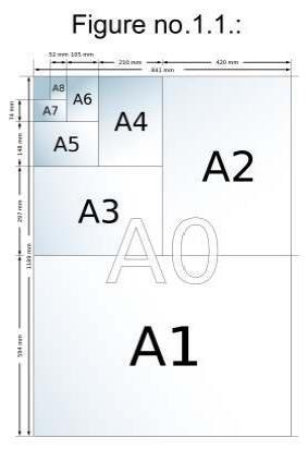
4 Page 5

5 Layout of drawing Sheet: Given specification are to be followed before commencing the sheet work. Note: all dimensions are in mm Lists of drawing instruments:- The following set of drawing instruments and materials are required in the preparation of engineering drawing sheet. 1. Drawing board (provided) 2. Drawing sheet(a-2 Size) 3. Mini Drafter 4. Instrument dividers box containing compass and 5. Set squares 6. Drawing pin or clips or cello tape (30-60, ) 7. Protractor 8. Drawing pencils (HB, H, 2H, 3H) 9. Eraser, Sharpener, Scale, 10. Plastic Sheet Holder. Circle Master, Dusting Cloth. Page 6
6 Convention of lines: Page 7
7 Arrow Head: It is used as terminator on dimension lines. The points of the arrow heads on leader lines and dimension lines must make the contact with the feature object line or extension line which represents the feature being dimensioned. The standard size ratio for all arrow heads on mechanical drawings is 3:1 (Length to Width). Figure1.2: Dimensioning Page 8


8 Dimensioning: 1. Dimensions should be placed outside the views, except when they are cleaner more easily readable inside. 2. Dimension lines should not cross each other 3. As far as possible, dimension should not be shown between the dotted lines. 4. Dimension lines should be placed at about 6mm from the outlines. 5. Head should be pointed and filled in. they are made in ratio 3 to1 (Length) Lettering: - Writing titles, dimension, notes and other important particulars on a drawing is called lettering should therefore be done properly in clear, legible and uniform style preferably freehand and speedily. Types of letters:- 1. Single stoke letters:- in these letters, the thickness o line of the letter should be such as is obtained in one stoke of the pencil Single stoke letters of two types:- (1) Vertical (2) Inclined Inclined letters lean to the right at angle of with the horizontal. The ratio of height to width various but in case of most of the letters it is 7:4. These are shown in following figure Gothic letters: - if stems of single stroke letters, are given more thickness, the letters are known as gothic letters. Page 9
9 QUESTION OF SHEET NO.1 1. Write alphabets in capital and numerals in single stroke with 7:4 ratio only (Without Using Scale). 2. Draw the Conventional of lines with their description. 3. Draw the Figure No.1.2 with proper dimensioning as per rules. Page 10


10 Sheet No.: 2 PROJECTION OF POINTS Projection: If straight lines are drawn from various points on the contour of an object, to meet a plane of projection, the object is said to be projected on that plane. The figure is formed by joining, in correct sequence. The points at which these lines meet theplane of projection, is called projection of the object. The line from the object to the plane of projection is called projectors as shown in the figure Figure 2.1: Projection Orthographic Projection: When projectors are parallel to each other and also perpendicular to the plane of projection the projection is called Orthographic projection. The necessary condition for orthographic projections is that the observer should be at infinite distance w.r.t. object. Page 11
11 Planes of Projection: Two planes used for the orthographic projection are called reference planes or principal plane of projection. They intersect each other at right angles. They are known as:- (i) Vertical Plane (VP) (ii) Horizontal Plane (HP) The vertical plane is often called the frontal plane and denoted by the letters F.P. Projection on vertical plane (VP) is called front view or elevation. Projection on the HP is called the top view or the plan. The line of intersection of vertical plane and Horizontal Plane is called reference line and is denoted by letter XY. Profile Plane: A plane perpendicular to HP and VP is called profile plane. Projection on profile plane is called side view or end view. Four Quadrants: When the planes of projection are extended beyond the line of intersection, they form four quadrants or dihedral angles. They are numbered as first, second, third and fourth quadrant. The object may be situated on any one of the quadrants. The position of the object relative to planes is described as above or below HP in front of or behind the VP. The planes of projections are assumed to be transparent. The projections are obtained by drawing projectors from the object to the planes (VP and HP) by looking from the front or from the above. The quadrants are shown in figure 2.2. Page 12

12 Figure 2.2: The four Quadrants When the object lies in the first quadrant; it means it may lie: Above HP and in front of VP Or on HP and in front of VP Or on VP and above HP When the object lies in the second quadrant, it means it may be: Above HP and behind VP Or on HP and behind VP Or above HP and on VP When the object lies in the third quadrant, it means it may be: Below HP and behind VP On HP and behind VP Below HP and on VP When object lies in the fourth quadrant, it means it may be: Below HP and front of VP On HP and in front of VP Below HP and on VP Page 13
 In this method, when views are drawn in their relative position, the top view comes below the front view. In other words, the view seen from above is placed on other side (i.e. below) the front view.")
13 Figure 2.3: Front View (Elevation) & Top View (Plan) First Angle Projection: (i) The object lies between observer and plane of projection. (ii) In this method, when views are drawn in their relative position, the top view comes below the front view. In other words, the view seen from above is placed on other side (i.e. below) the front view. (iii) Similarly left hand and view is drawn on the right side of front view and right hand side view is drawn on the left of front view. Convention of first angle projection: Third Angle Projection: (i) Plane of Projection is lies between object and observer. (ii) In this method, when views are drawn in their relative position, the top comes above the front view. In other words, the view Page 14
14 (iii) seen from above is placed on the same side (i.e. above) of front view. Left hand end view is drawn at left hand of front view and right hand end view is drawn at the right side of front view. Convention of third angle projection Note: Students are required to draw on drawing Projection. sheets in 1 st Angle As per Indian code of practice for general engineering Drawing, published in 1973, the committee responsible for preparation has left the option of selecting first or third angle projection method to users. Projection of points in different quadrants 1. Point A is h mm above HP and g mm in front of VP. first quadrant. Point A is in 2. Point B is in the h mm above HP and g mm behind VP. Hence B in the second quadrant. Page 15

15 To draw a projection i.e. front view b and top view b on the paper, once the third quadrant is open, HP coincide with VP and both HP & VP are above the XY line. 3. Point C is h mm below HP and g mm behind VP. Hence point C in the third quadrant. To draw the projections (c and c) on the paper, once the third quadrant is open, HP lies above XY line and VP below the XY line and draw top view above the XY line and front view below the XY line. 4. Point D is h mm below HP and g mm in front of VP. Hence point D is in the fourth quadrant. To draw projections (Front view d and top view d), once the 1 st quadrant is opened, HP concedes with VP and both will be below the XY line. Hence front view and top view will be below the XY line. Page 16
16 Note: (i) (ii) Distance of the point above the HP or below the HP is indicated by the position of front view. Distance of the point in front of VP or behind VP is indicated by the position of top view. Page 17
17 QUESTION OF SHEET NO.2 1. Draw the projections of the following points taking common reference line, keeping the distance between any two consecutive points as 20mm. (i) Point A 35 mm in front of VP and 35 mm above HP. (ii) Point B is in HP and 30 mm in front of VP (iii) Point C is 30 mm above HP and 45 mm behind VP. (iv) Point D is in VP and 45 mm above HP. (v) Point E is 35 mm below HP and 55 mm behind VP (vi) Point F is in VP and 45 mm below HP. (vii) Point G is both HP and the VP. 2. A point P is 15 mm above HP and 20 mm infront of VP. Another part Q is 25 mm behind the VP and 40 mm below HP. Draw the projections of P and Q, keeping the distance between their projectors 75 mm, draw straight lines joining their (i) top views (ii) Front views. 3. Two point A and B are in HP. Point A is 30 mm infront of VP, while B is behind the VP. The distance between their projectors 75 mm and line joining their top views makes an angle of 45 with XY. Find the distance of the point B from the VP. 4. A point P is 25 mm below HP and its shortest distance form XY(reference line) is 50mm. the point P lies in the third quadrant. Draw its projection. Page 18
18 SHEET NO.:3 PROJECTION OF STRAIGHT LINES-I A straight line is the shortest distance between the two points. Hence projection of straight line may be drawn by joining the respective position of its ends, which are points. The position of straight line is described with reference two reference planes. It may be 1. Parallel to HP and VP. 2. Perpendicular to HP and parallel to VP or perpendicular to VP and parallel to HP. 3. Inclined to HP and parallel to VP or Inclined to VP and parallel to HP. 4. Inclined to HP and VP. I. A line AB is parallel to HP and VP Since line AB is parallel to HP and VP. Its front view a`b` and top view ab will show true length of line AB and will be parallel to XY line II. A line AB is perpendicular HP and parallel to VP Since a line is perpendicular to HP. It will be automatically parallel to VP since it is parallel to VP, front view will show true length of line AB and top view will be a point, where points a & b will meet. Page 19

19 III. A line AB is perpendicular to VP and parallel to HP. Since the line AB is parallel to HP. Top view will show true length of line AB and will be perpendicular to any line. Front view will be point, where both points a and b will meet. IV. A line AB is Inclined to HP and parallel to VP. Since the line AB is parallel to VP. From view will show true length of line and true inclination with HP so knowing the position of point A (as given in question) projection of end A are drawn. From the point A, line a`b` is drawn equal to length of line AB at an angle Ɵ with HP since the line AB is parallel to VP, top view ab will be parallel to XY. V. A line AB included to VP and parallel to HP. Since the line AB is parallel to HP. Top view ab will show true length of line AB and true inclination with VP (ɸ). Projection of points A as per given in the question drawn as a and a. Draw line ab as top view at angle ɸ with VP. Front view a`b` will be parallel to xy line. Page 20
20 VI Line AB inclined to both HP and VP A given line may be inclined to both the reference planes i.e. HP and VP. In such cases, length of line and its inclination with HP and VP may be given; it may be required to draw its projections. In another case, projections of line may be given, and it may be required to determine its true length and its inclinations with HP an VP. I Case: Length of line AB and its inclination and with HP and with VP are given. Position of point A is also given. Projections are to be drawn. a b 1 = Front view of Line AB ab1 = Top view of Line AB Procedure: - Draw the front view a and top view a of the point A as per given question:- - From a draw line a b equal to true length of line AB and at angle Ɵ with the HP. - From the point a, draw a line ab equal true length of line AB and at angle ɸ with VP. Page 21
21 - Draw locus ef, rs, pq and cd from the b,a, a and b respectively, parallel to XY line. For example ef is locus of point b. - If a b is true length of line AB a b 2 projected length of a b and is equal to length of top view of line AB. - Further project the point b 2 on locuslinepq such that a b2 = ab2 = length of top view. - Now bring the point b2 on the locus of point b i.e. line cd. Take a as centre and radius equal to ab2, draw arc b2b1. Join a to b1. ab1 is the length of top view. - Similarly of ab is true length of line AB, ab3 = a`b`3 = length of front view. - Take a as centre and radius equal to a`b`3, and draw arc b3 b1 to bring point b3 on locus of point b i.e. ef Join a to b 1 Hence ab3 = a b3 = a b 1 = length of front view. Note: Point b1 and b1 projections of point b should lie on the same vertical line. II Case: Determination true length of a line and its inclination with HP and VP when projections are given. Front view a b and top view ab of line AB are given. Determine true length of line AB and inclination Ɵ with HP and ɸ with VP. Problem can be solved by two methods. (i) Method of rotation. (ii) Trapezoid Method. METHOD OF ROTATION Principle: Now if front view a b is made parallel to XY, the line AB becomes parallel to HP and its projection ab1 on HP shows its true length and true inclination with VP. Page 22
22 Similarly if top view ab of line AB is made parallel to VP, the line AB becomes parallel to VP and its projection on VP show its true length and true inclination with HP Procedure: Draw locus of point b,a, a and b i.e. lines ef, rs, pq and cd respectively parallel to XY. Take a as centre and radius equal to a b and draw arc b b2 to make front view a b parallel to XY and line AB becomes parallel to HP. Project point b2 on the locus of point b. Join a to b1. ab1 is true length of line AB and show true inclination ɸ with VP. Similarly take a as centre and radius equal to ab, draw an arc bb2, to make top view ab parallel to XY. Now line AB becomes parallel to VP and its projection on VP shows its true length and true angle of inclination with HP. Page 23
23 QUESTION OFSHEET NO.3 1. Straight line AB 40 mm long makes an angle of 30 to the HP. The end A is 10 mm above the HP and 15 mm in front of the VP. Draw the top view and front view of the line AB. 2. Straight line AB 60 mm long makes an angle of 55 to the VP and 25 to the HP. The end A is 10 mm above the HP and 10 mm infront of the VP. Draw the projections of the line AB. 3. Straight line AB 60 mm long makes an angle of 55 to the VP and 25 to the HP. The one end of the straight line AB lies in the HP and is 20 mm infront of the VP. Draw the projections of the line AB. 4. A straight line AB is 50 mm long. Its one end A is 40 mm from the H.P. and 10 mm from V.P. and other end B is 30 mm from the V.P. and 20 mm from the H.P. Draw the projections. Page 24
24
25 Sheet No.:4 PROJECTION OF STRAIGHT LINES-II TRAPEZOID METHOD Procedure: Draw the projections i.e. front view and top view of line AB as per question. A the point a draw perpendicular a A equal to distance of point A from XY. Further draw perpendicular b B1 equal to distance of b from XY line. Join A1 to B1. A1B1 shows true length of line AB. Line A1B1 and a b will make angle ɸ, inclination with VP if extended back. Similarly draw perpendicular aa2 at a equal to distance to distance of a from XY. Further draw perpendicular bb2 at b equal distance of b from XY join A2 to B2. A2B2 shows the true length of line Ab. Line ab and A2B2 will make angle Ɵ, inclination with HP if extended back. Page 25
26 Traces of a Line: When a line is inclined to a plane, it will meet that plane produced if necessary. The point of intersection of line and plane is called trace. Horizontal Trace (HT): If a line is inclined to HP, it will meet Horizontal plane then the point of intersection of line and HP is called horizontal trace (HT). Vertical Trace (VT): If a line inclined to VP; it will meet the vertical plane. The point of intersection of line (produced back if necessary) with the VP plane is called vertical trace. Note 1: If a line is inclined to HP and VP. A will have both HT and VT. Note 2: If a line is parallel to any reference plane it will have not trace with that plane. Determining Traces of A Line: (1) A line AB is inclined to HP and parallel to VP Draw the front view a b and top view ab of line. Angle of inclination Ɵ with HP is shown by front view. Produced back front view a b till it intersect XY line at point C. From C draw perpendicular on top view ab (produced back) at a point called HT. Page 26
27 (2) A line AB is inclined to VP and parallel to HP Draw the projections (Front view a b and top view ab) of line AB Angle of inclination ɸ with VP is shown by its top view. Produce back top view ab till it cuts the XY line at D. From D draw perpendicular on the extended front view a b. Point of intersection of front view and perpendicular from D is the vertical trace. (3) A line AB is inclined to HP and VP: Draw the projections (front view a b and top view ab) of line AB. Produce back front view a b till it cut the XY line at C. From C draw perpendicular on extended top view to get HT. Produce back top view ab. It cuts the XY line at D. From D draw perpendicular on the extended front view to get VT. Page 27
28 QUESTION OF SHEET NO. 4 PROJECTIONS OF LINES II 1. A line AB, 65mm long, has its end A 20mm above HP and 25 in front of VP. The end B is 50mm above HP and 65 mm in front of VP. Draw the projections of line AB and show its inclination with HP & VP (Rotational Method). 2. A line AB has its end A 7 mm behind VP and 18mm below HP. The end B 38mm behind VP and 49mm below HP. The distance between the end projectors is 37mm. Draw the projection of line and find out 8,, HT, VT & TL (Rotational Method). 3. The distance between the projectors of a line is 40 mm. The end A is 20 mm away from HP and 30 mm away from VP & the end B is 50 mm away from HP and 10 mm away from VP. Draw the projection of line AB and determine its 8,, HT, VT & TL (Trapezoid Method). 4. The end A of line AB is in the HP and 25mm behind VP. The end B is in the VP and 50mm above the HP. The distance between the projectors is 75mm. Draw the projections of line AB, and determine its true length, traces, inclination with HP & VP (Trapezoid Method). Page 28
29 SHEET NO.: 5 PROJECTION OF PLANES Plane Surfaces: Plane surfaces have only two dimensions i.e. length and breadth. They do not have thickness. A plane surface may have triangular, rectangular, square, pentagonal or hexagonal shape. Types of Planes: Plain may be divided in two main types:- (i) Perpendicular planes (ii) Oblique planes Perpendicular planes can be sub divided into following sub types: (a) Perpendicular to both the reference planes (b) Perpendicular to one reference plane and parallel to other (c) Perpendicular to one reference plane and inclined to other Oblique Planes: Planes which are inclined to both the reference planes are called oblique planes. Traces of Planes: If a plane is perpendicular or inclined to a reference plane, the line in which plane surface meet with reference plane is the trace of plane. The line in which, the plane meet the HP, is called Horizontal Trace (HT). The line in which it meets with VP is called vertical trace (VT). Perpendicular Planes: (i) A square plane is perpendicular to HP and VP: Projection are shown in fig. 5.1 Page 29

30 Figure 5.1 (iii) A square plane perpendicular to HP and parallel to VP. Since the plane is parallel to VP front view a b c d will show its true shape and top view will be a straight line parallel to XY as shown in fig. 5.2 Figure 5.2 Since the plane is perpendicular to HP, it has HT and no VT, since it is parallel to VP. (iii) A square plane perpendicular to VP and parallel to HP. Since the plane is parallel to HP, top view abcd will show its shape but no HT. Front view will be straight line parallel to XY and it also represent VT as in fig. 5.3 Page 30
31 Figure 5.3 (iv) Square plane perpendicular to HP and inclined to VP. First assume, the plane is parallel to VO. Draw front view a b c d first and project top view from the front view. In the second stage, rotate top view ad-bc at angle ɸ, inclination with VP. New top view will be ad b1c1 Project points b1c1 to get point b 1 and c 1 in the front view to get final front view a b 1c 1d. Figure 5.4 Page 31
32 (v)a square plane perpendicular to VP and inclined to HP First assume parallel to HP and perpendicular to VP top view abcd will show the true shape of square plane. Project front view a d -b c from top view. Figure 5.5 In the second stage rotate front view a d b c by an angle Ɵ, inclination with HP to get new front view a d -b 1c 1. Project the point b 1c 1 on top view to get point b1 and c1 and to get new top view ab1c1d. (vi) Oblique Planes: The projection of planes, inclined to both the reference planes is drawn in three stages as per the conditions given in the question. Page 32
33 QUESTION OF SHEET NO.5 1. A regular pentagon of 25 mm side has one of its side in the HP. Its plane is inclined at 45 0 to HP and perpendicular to VP. Draw its projections. 2. To project the front view and top view of a hexagon ABCDEF of 25 mm side with its base on or above H.P. and inclined to V.P. at A circular plate (ABCDEFGH) of diameter 80 mm is 15 mm above HP such that it makes an angle 30 0 to the HP. The top view of diameter DH makes an angle of 60 0 with VP. Draw the projections. 4. A square ABCD of 50 mm side has its corner A on the HP. Its diagonal AC is inclined at 30 0 to HP and its diagonal BD is inclined at 45 0 to VP and parallel to HP. Draw its projections. Page 33
34 SHEET NO.: 6 PROJECTION OF SOLIDS A solid has three dimensions, viz. length, breadth and thickness. To represent a solid on flat surface having only length and breadth, at least two orthographic views are necessary. Sometimes, additional views are projected on Auxiliary planes, if necessary to make the description of a solid complete. Solids may be divided into two main groups:- (i) Polyhedral (ii) Solids of revolutions Polyhedral: Polyhedral are defined as solid bounded by planes called faces. When all the faces are equal and regular, the polyhedron is said to be regular. There are five regular polyhedral which may be defined as stated below:- (i) Tetrahedron: It has four equal faces, each one is equilateral triangle. (ii) Cube or hexahedron: It has six faces, each face is square. (iii) Octahedron: It has eight faces. Each face is an (iv) equilateral triangle. Dodecahedron: It has twelve equal faces and each face is regular pentagon. (v) Icosahedrons: It has twenty faces. Each face is an equilateral triangle. Prism: Prism is a polyhedron having two equal and similar faces called its ends or bases, parallel to each other and joined by other faces, which are parallelograms. The imaginary line joining the centre of the bases is called axis. A right regular prism has its axis perpendicular to the bases. The bases may be triangular, square, pentagonal or hexagonal in shape. Page 34


35 Accordingly they called as triangular, square, pentagonal hexagonal prism. Pyramid: Pyramid is a polyhedron having a plane figure as base and number of triangular faces meeting at a point called the vertex or apex. The imaginary line joining the apex with the centre of base is its axis. A right and regular pyramid has its axis perpendicular to base which is a regular plane figure. Its faces are equal isosceles triangle. As per shape of the base, they are called as Triangular, square, pentagonal and hexagonal pyramid. TRIANGULAR PYRAMID SQUARE PYRAMID PENTAGONALPYRAMID Page 35
36 SOLID OF REVOLUTIONS: A right circular cylinder is a solid generated by the revolution of a rectangle about one of its sides which remain fixed. It has two circular bases. The joining the center of the bases is the axis. It is perpendicular to the bases. A right circular cone is a solid generated by the revolution of a right angled triangle about one of its perpendicular sides which is fixed. It has one circular base. Its axis joins the apex with the centre of the base to which it is perpendicular. Straight lines drawn from the apex to the circumference of the base circle are all equal and are called generators of the cone. The length of generator is the slant height of the cone. CYLINDER CONE SPHERE Figure 6.1: SOLIDS A sphere is a solid generated by the revolution of a semicircle about its diameter as the axis. The midpoint of diameter is the centre of sphere. Frustum of a solid: When a pyramid or a cone is cut by a plane parallel to its base, thus removing the top portion, the remaining portion is called its frustum. Truncated Solid: When a solid is cut by a plane inclined to the base, it said to be truncated. A solid may be inclined to one or both the reference planes. Accordingly projections are drawn in two and three stages respectively. Page 36
37 QUESTION OF SHEET NO.6 1. Draw the projections of a pentagonal prism, base 25 mm side and 50 mm long, resting on one of its rectangular faces on HP with its axis inclined at 45 to VP. 2. Draw the projections of a cylinder 75 mm diameter 100 mm long, lying on the HP with its axis inclined 30 to VP and parallel to HP. 3. A hexagonal pyramid, base 25 mm side and axis 50 mm long, has an edge of its base on the HP. Its axis is inclined at 30 to HP and parallel to VP. Draw the projections. 4. Draw the projections of a cone, base 75 mm diameter and axis 100 mm long, lying on the HP on one of its generator, with the axis parallel to VP. 5. Draw the projection of cone, base 50 mm diameter and axis 55 long, when it is resting on the HP on its base circle with the axis making an angle of 30 with HP and its top view making 45 with the VP. Page 37
38 SHEET NO.: 7 SECTION OF SOLIDS In the projected views of an object, invisible features are shown by dotted lines. But when such features are too many, these lines make the view more complicated and difficult to interpret. In such cases, it is customary to imagine the object as being cut through or sectioned by planes. This imaginary plane is called the sectioned plane or the cutting plane. The part of the object between cutting plane and observer is assumed to be remove and the view is than shown in sections The projection of the section along with remaining portion of the object is called sectional view. The surface produced by cutting the object by the section plane is called the section. It is indicated by thin section line uniformly spaced and inclined at 45 o. Section planes:- section planes or cutting planes are generally perpendicular planes. They may be perpendicular to one of the reference planes and either perpendicular parallel or inclined to other reference plane. They are usually described by their traces. It is important to note that projection of the section plane, on the plane to which it is perpendicular, is a straight line, this line will be parallel, perpendicular or inclined to XY, depending upon the section plane being parallel, perpendicular, or inclined respectively to other reference plane. This straight line coincides with the trace of section plane. True shape of the section:- The projection of the section on a reference plane, parallel to the section plane, will show the true shape of the section. Thus when, section plane is parallel to HP, the true shape of the section will be seen in sectional top view. When it is parallel to VP, the true shape will be visible in the sectional front view. But when the section plane is inclined the section has to be projected on an auxiliary plane, parallel to the section plane, to get the true Page 38
39 shape. When the section plane is perpendicular to both the reference planes, the sectional side view will show the true shape of the section. Table 7.1: Conventions of Materials Page 39
40 QUESTION OF SHEET NO.7 1) A right regular pentagonal pyramid side of base 40 mm and ht. 60 mm rest on its base in HP with one of its base edge perpendicular to VP. A section plane parallel to the HP cuts the axis of the pyramid at a distance of 25 mm from its base draw its front view and sectional top view. 2) A right regular pentagonal prism, base edge 40 mm and ht. 70mm is held on HP one of its base edge such that its axis is parallel to the VP and inclined to HP at 30 o. An auxiliary horizontal plane cuts the prism, intersecting its axis at a distance of 17 mm from its top end. Draw its front view and sectional top view. 3) A right regular pentagonal pyramid, side of base 40mm and ht. 70mm, rest on its base on HP, such that one its base edges perpendicular to the VP. A section plane parallel to VP cuts the pyramid and is at a distance of 8mm from the axis. Draw its top view and sectional front view. 4) A right circular cone diameter of base 60mm and ht. 70mm, rest on its base on HP. A section planes perpendicular to VP and inclined to HP at 45 o, cuts the cone meeting its axis at the distance 36mm from its base. Draw its front view, sectional top view and true shape of section. Page 40
: When different straight lines are drawn from various points on the contour of the object on to the plane of drawing")
41 SHEET NO.: 8 ORTHOGRAPHIC PROJECTION - 1 PROJECTIONS AND PROJECTION LINES (PROJECTORS): When different straight lines are drawn from various points on the contour of the object on to the plane of drawing sheet, the figure obtained on the sheet by joining different points in the correct order is known as Projection of that object (Refer the Following Figure 8.1). And the lines drawn from various points on the contour of the object on to the plane of drawing sheet are called Projectors or Projection Lines. Figure 8.1: Projection and projection lines ORTHOGRAPHIC PROJECTION: The image of the object obtained on the plane of projection when the projectors are from the various points on the object, parallel to each other and perpendicular to the plane of projection, then the image obtained on the plane of projection is called Orthographic Projection. Page 41


42 In case of simple object, only two orthographic views are required to show the length, breadth and height of the object. But in some cases, it becomes essential to show three orthographic projections of the object to give complete information needed for the construction of an object. Page 42
43 QUESTION OF SHEET NO.8 1. Following figure shows the pictorial view of a block. Draw to a full size scale, the following views in first angle projection: a. Front View (Elevation) seen from A b. Side View seen from B c. Top View (Plan) seen from C 2. Following figure shows the pictorial view of a block. Draw to a full size scale, the following views in first angle projection: a. Elevation from F ; b. Side View & c. Plan. Page 43
44 3. Following figure shows the pictorial view of a block. Draw to a full size scale, the following views in first angle projection: a. Elevation from F ; b. Side View & c. Plan. 4. Following figure shows the pictorial view of a block. Draw to a full size scale, the following views in first angle projection: a. Elevation from F ; b. Side View & c. Plan. Page 44
45 SHEET NO.: 9 QUESTION ON ORTHOGRAPHIC PROJECTION 2 1. Draw orthographic projection (free hand) of all the wooden blocks (No. of blocks 10). Page 45
46 SHEET NO.: 10 ISOMETRIC PROJECTION ISOMETRIC VIEW The three dimensional view or projection of an object obtained on a plane of projection in which all the projectors are parallel but inclined at an angle of 30 to the plane of projection is known as Isometric View. In this type of projection, the object is placed in such a way that all the three axes make equal angle with the plane of projection. It is easier to draw all the edges as compared with oblique or perspective projections. THEORY OF ISOMETRIC VIEW It is important to know how an isometric view is obtained on the plane of projection. Consider a cube. Let the three corners of the cube meeting at the forward corner is equally inclined to the plane of projection so that the projection to be obtained should give equal length. Therefore, any line so inclined is known as isometric line and the projection thus obtained, represent isometric projection or view. As three edges meeting at a point are equally inclined to each other, hence, the angle between two adjacent edges is equal to 360/3 = 120 o. The following figure 14.1 shows the isometric view of a cube in which the edges are parallel to the three main axes. All the edges of the cube are shortened equally. The square faces look as rhombuses. The rhombus AOBD as shown in fig The i sometric projection of the top square fall of the cube in which AB is the true length of the diagonal. A square ANBM is constructed is the true length of BD. It is seen from the figure 14.1 that when a line is inclined to the plane of projection, it does not give the exact size. It is very essential to know the proportion by which various edges of the cube are shortened. This can be found by means of a scale known as isometric scale. Page 46
47 DIFFERENT POSITIONS OF ISOMETRIC AXES To show the different sides of the object, the object is revolved about its three isometric axes as shown in the following figure: DIFFERENCE BETWEEN ISOMETRIC PROJECTION AND ISOMETRIC VIEW: The Isometric Projection means to draw always the Isometric sketch by using Isometric scale and the Page 47
48 ENGINEERING GRAPHICS ( ) Isometric scale must also be drawn along with the Isometric Projection. Isometric View means to draw Isometric sketch not necessarily taking measurements from the Isometric scale and the Isometric scale may or may not be drawn along with the Isometric view. In this case, measurements can be taken directly from the true orthographic projections because there is little difference between the isometric lengths and true length. Notes: (i) Always draw the Isometric Scale when it is mentioned in the question paper that draws the isometric projections. (ii) In case of Isometric View, Isometric Scale may or may not be drawn. Solution by both the methods is correct. Page 48
49 QUESTION OFSHEET NO Draw an isometric projection of an equilateral triangular prism having base edges of length = 35 mm and height = 50 mm; its end parallel to H.P. and one of rectangular face parallel to V.P. 2. Draw an isometric projection of a triangular pyramid of 30 mm base edges and 50 mm height standing on its base vertically. 3. Draw an isometric view of a frustum of a triangular pyramid having axis vertical, base edges = 30 mm, top edge = 15 mm and height = 40 mm. 4. The following figure shows the side view and front view of a machine block. Draw the isometric view of the block. 5. The following figure shows the side view and front view of a machine block. Draw the isometric view of the block. Page 49
50 SHEET NO.:11 SCALES INTRODUCTION Sometimes it is not possible to represent the actual size of the object on the drawing sheet e.g. building, bridge, etc. So the actual size of the object is reduced to some proportion in order to accommodate on the drawing sheet. At times, actual size of the object is so small that it becomes essential to increase the actual size to some proportion to give the clear view e.g. parts of small machine, watches, measuring instruments, etc. The proportion by which the actual size is increased or decreased on the drawing is known as scale. SCALE The proportion by which the actual size of the object is increased or decreased on the drawing is known as scale. Scales are flat or triangular made of wood, celluloid, metal, etc. In drawing, standard recommended scales should be used as far as possible. On scales, different divisions represent the corresponding actual distances to some proportion, which give rapidity in marking off distances on the drawing. SIZES OF SCALE The following sizes of the scales are used in Engineering Drawing: (i) Full Size Scale: The scale, in which the actual measurements of the objects are drawn to some size on the drawing, is called full size scale. It is written on scale strip as under. 1: 1 Drawing made to actual size. (ii) Reduced Scale: The scale, in which the actual measurements of the objects are reduced to some proportion, is called reduced scale. The standard reducing proportions are: 1: 2 Drawing made to one half of the actual size. 1: 5 Drawing made to one fifth of the actual size. 1 : 10 Drawing made to one tenth of the actual size. (iii) Enlarged Scale: The scale, in which the actual measurements of the objects are increased to some proportion, is called enlarged scale. The standard reducing proportions are: 1: 50 Drawing made to one fiftieth of the actual size. 2 : 1 Drawing made to twice the actual size. 5 : 1 Drawing made to five times the actual size. REPRESENTATIVE FRACTION The ratio of distance on the drawing sheet of an object to the corresponding actual distance of the object is known as Representative Fraction (R.F.). Page 50
51 Page 51
52 QUESTION OF SHEET NO To construct a plain scale to show meters and decimeters if one meter is represented by 2.5 cm and scale is long enough to measure up to 6 meters. 2. To construct a plain scale to show meters and decimeters if one 0.4 meter is represented by 1 cm and scale is long enough to measure up to 5 meters. Find R.F. and show a distance of 4 meters and 5 decimeters on the scale. 3. To construct a diagonal scale to show meters, decimeters and centimeters and long enough to measure 6 meters. If 1 meter is represented by 2.5 centimeters, find the R.F. and show on the scale, a distance of 4 meters, 5 decimeters and 6 centimeters 4. To construct a diagonal scale of R.F. = 1/5000 to show single meters and long enough to measure up to 600 meters. On the scale, show a distance of 457 meters Page 52
Drawing sheet: - The various size of the drawing sheet used for engineering drawing as per IS Are listed in the table
 Dronacharya Group of Institutions, Greater Noida Computer Aided Engineering Graphics (CAEG) (NCE 151/251) List of Drawing Sheets: 1. Letter writing & Dimensioning. 2. Projection of Points & Lines. 3. Projection
APJ ABDUL KALAM TECHNOLOGICAL UNIVERSITY SECOND SEMESTER B.TECH DEGREE EXAMINATION, MAY PART A Answer ANY Two questions. 10 marks each.
 B B2B111 Pages: 2 Reg. No. Name: SECOND SEMESTER B.TECH DEGREE EXAMINATION, MAY 2017 Max.Marks:50 Course Code: BE110 Duration:3Hours Answer ANY Two questions. 10 marks each. 1. A line AB 100 mm long and
TPCT s College of Engineering, Osmanabad. Laboratory Manual. Engineering Graphics. For. First Year Students. Manual Prepared by B. G.
 TPCT s College of Engineering, Osmanabad Laboratory Manual Engineering Graphics For First Year Students Manual Prepared by B. G. Kadam Author COE, Osmanabad TPCT s College of Engineering Solapur Road,
4. Draw the development of the lateral surface of the part P of the cylinder whose front view is shown in figure 4. All dimensions are in cm.
 Code No: Z0122 / R07 Set No. 1 I B.Tech - Regular Examinations, June 2009 ENGINEERING GRAPHICS ( Common to Civil Engineering, Mechanical Engineering, Chemical Engineering, Bio-Medical Engineering, Mechatronics,
GE ENGINEERING GRAPHICS
 ANNA UNIVERSITY, CHENNAI (REGULATION GE8152 - ENGINEERING GRAPHICS B.E SEMESTER I Lecture Tutorial Practical Marks Credits Total Hours 2 0 3 100 4 90 Mr.S.Gokul (Asst. Prof/Mech) Sri Eshwar College of
BVRIT HYDERABAD College of Engineering for Women Department of Basic Sciences and Humanities
 BVRIT HYDERABAD College of Engineering for Women Department of Basic Sciences and Humanities Hand Out Subject Name: Engineering Graphics Prepared by (Faculty(s) Name): Mr. M Gopikrishna, Asst.Professor,
Second Semester Session Shri Ramdeobaba College of Engineering & Management, Nagpur. Department of Mechanical Engineering
 Second Semester Session- 2017-18 Shri Ramdeobaba College of Engineering & Management, Nagpur. Department of Mechanical Engineering Engineering Drawing Practical Problem Sheet Sheet No.:- 1. Scales and
Set No - 1 I B. Tech I Semester Regular/Supplementary Examinations Jan./Feb ENGINEERING DRAWING (EEE)
") Set No - 1 I B. Tech I Semester Regular/Supplementary Examinations Jan./Feb. - 2015 ENGINEERING DRAWING Time: 3 hours (EEE) Question Paper Consists of Part-A and Part-B Answering the question in Part-A
Set No - 1 I B. Tech I Semester Regular/Supplementary Examinations Jan./Feb. - 2015 ENGINEERING DRAWING Time: 3 hours (EEE) Question Paper Consists of Part-A and Part-B Answering the question in Part-A
Chapter 4 ORTHOGRAPHIC PROJECTION
 Chapter 4 ORTHOGRAPHIC PROJECTION 4.1 INTRODUCTION We, the human beings are gifted with power to think. The thoughts are to be shared. You will appreciate that different ways and means are available to
ENGINEERING DRAWING
 Subject Code: R13109/R13 Set No - 1 I B. Tech I Semester Regular/Supplementary Examinations Jan./Feb. - 2015 ENGINEERING DRAWING (Common to ECE, EIE, Bio-Tech, EComE, Agri.E) Time: 3 hours Max. Marks:
ENGINEERING DRAWING. UNIT III - Part A
 DEVELOPMENT OF SURFACES: ENGINEERING DRAWING UNIT III - Part A 1. What is meant by development of surfaces? 2. Development of surfaces of an object is also known as flat pattern of the object. (True/ False)
ISOMETRIC PROJECTION. Contents. Isometric Scale. Construction of Isometric Scale. Methods to draw isometric projections/isometric views
 ISOMETRIC PROJECTION Contents Introduction Principle of Isometric Projection Isometric Scale Construction of Isometric Scale Isometric View (Isometric Drawings) Methods to draw isometric projections/isometric
ENGINEERING DRAWING. 1. Set squares are used to draw different angles. What is the angel a formed by the 45⁰ set square? Give a brief answer.
 ENGINEERING DRAWING 1. Set squares are used to draw different angles. What is the angel a formed by the 45⁰ set square? Give a brief answer. 2. Which is the correct method of hatching a plane surface?
Unit-5 ISOMETRIC PROJECTION
 Unit-5 ISOMETRIC PROJECTION Importance Points in Isometric: 1. For drawing the isometric, the object must be viewed such that either the front -right or the left edges becomes nearest. 2. All vertical
INSTITUTE OF AERONAUTICAL ENGINEERING
 Course Name Course Code Class Branch INSTITUTE OF AERONAUTICAL ENGINEERING Dundigal, Hyderabad - 500 043 MECHANICAL ENGINEERING TUTORIAL QUESTION BANK : ENGINEERING DRAWING : A10301 : I - B. Tech : Common
SIDDHARTH GROUP OF INSTITUTIONS :: PUTTUR
 SIDDHARTH GROUP OF INSTITUTIONS :: PUTTUR Siddharth Nagar, Narayanavanam Road 517583 QUESTION BANK Subject Code : Engineering Graphics& Design Course & Branch : B.Tech ALL Year & Sem : I B.Tech & I Sem
GOVERNMENT POLYTECHNIC, VALSAD MECHANICAL ENGINEERING DEPARTMENT ASSIGNMENT SUB: MECHANICAL DRAFTING (C321901) TERM:172
 TERM:172") GOVERNMENT POLYTECHNIC, VALSAD MECHANICAL ENGINEERING DEPARTMENT ASSIGNMENT SUB: MECHANICAL DRAFTING (C321901) TERM:172 1) When all the dimension are placed above the dimension line, it is called (a) Aligned
GOVERNMENT POLYTECHNIC, VALSAD MECHANICAL ENGINEERING DEPARTMENT ASSIGNMENT SUB: MECHANICAL DRAFTING (C321901) TERM:172 1) When all the dimension are placed above the dimension line, it is called (a) Aligned
Engineering Graphics. Practical Book. Government Engineering College Bhuj (Kutch - Gujarat) Department of Mechanical Engineering
 Department of Mechanical Engineering") Engineering Graphics Practical Book ASHISH J. MODI Department of Mechanical Engineering Government Engineering College Bhuj 370 001 (Kutch - Gujarat) SYLLABUS (AS PER GUJARAT TECHNOLOGICAL UNIVERSITY,
Engineering Graphics Practical Book ASHISH J. MODI Department of Mechanical Engineering Government Engineering College Bhuj 370 001 (Kutch - Gujarat) SYLLABUS (AS PER GUJARAT TECHNOLOGICAL UNIVERSITY,
Chapter 5 SECTIONS OF SOLIDS 5.1 INTRODUCTION
 Chapter 5 SECTIONS OF SOLIDS 5.1 INTRODUCTION We have studied about the orthographic projections in which a 3 dimensional object is detailed in 2-dimension. These objects are simple. In engineering most
GE 6152 ENGINEERING GRAPHICS
 GE 6152 ENGINEERING GRAPHICS UNIT - 4 DEVELOPMENT OF SURFACES Development of lateral surfaces of simple and truncated solids prisms, pyramids, cylinders and cones - Development of lateral surfaces of solids
I B.TECH- I SEMESTER DEPARTMENT OF MECHANICAL ENGINEERING ENGINEERING DRAWING
 I B.TECH- I SEMESTER DEPARTMENT OF MECHANICAL ENGINEERING ENGINEERING DRAWING ENGINEERING DRAWING UNIT-V DEFINITIONS: Axonometric Trimetric Dimetric Isometric It is a parallel technique used to create
NOTE: Topic No. 1, 8 and 9 of the above syllabus to be covered in Practical Hours.
 Subject Engineering Graphics Teaching scheme Theory Tutorial Practical Credits 2 0 4 6 Engineering Graphics syllabus 1. Introduction to Engineering Graphics, Drawing instruments and accessories, BIS SP
Engineering Graphics- Basics.
 Engineering Graphics- Basics DRAWINGS: ( A Graphical Representation) The Fact about: If compared with Verbal or Written Description, Drawings offer far better idea about the Shape, Size & Appearance of
ENGINEERING GRAPHICS UNIT V ISOMETRIC PROJECTION PERSPECTIVE PROJECTION
 ENGINEERING GRAPHICS UNIT V ISOMETRIC PROJECTION PERSPECTIVE PROJECTION 1.PICTORIAL PROJECTIONS To visualize the shape of the whole object in its 3- D form, all the two or three orthographic views of the
6. Draw the isometric view of a cone 40 mm diameter and axis 55 mm long when its axis is horizontal. Draw isometric scale. [16]
![6. Draw the isometric view of a cone 40 mm diameter and axis 55 mm long when its axis is horizontal. Draw isometric scale. [16]](/thumbs/85/92603403.jpg "6. Draw the isometric view of a cone 40 mm diameter and axis 55 mm long when its axis is horizontal. Draw isometric scale. [16]") Code No: R05010107 Set No. 1 I B.Tech Supplimentary Examinations, Aug/Sep 2007 ENGINEERING GRAPHICS ( Common to Civil Engineering, Mechanical Engineering, Mechatronics, Metallurgy & Material Technology,
Code No: R05010107 Set No. 1 I B.Tech Supplimentary Examinations, Aug/Sep 2007 ENGINEERING GRAPHICS ( Common to Civil Engineering, Mechanical Engineering, Mechatronics, Metallurgy & Material Technology,
B.E. 1 st Year Engineering Graphics ( )
") B.E. 1 st Year Engineering Graphics (2110013) Department of Mechanical Engineering Darshan Institute of Engg. & Tech., Rajkot Darshan Institute Of Engg. & Technology List Of Instruments SR NO. 1. Set-Square
B.E. 1 st Year Engineering Graphics (2110013) Department of Mechanical Engineering Darshan Institute of Engg. & Tech., Rajkot Darshan Institute Of Engg. & Technology List Of Instruments SR NO. 1. Set-Square
ENGINEERING GRAPHICS (Engineering Drawing is the language of Engineers)
") ENGINEERING GRAPHICS (Engineering Drawing is the language of Engineers) UNIT 1 Conic Section (Ellipse, Parabola & Hyperbola) - Cycloids, epicycloids, hypocycloids & Involutes around circle and square scales
ENGINEERING GRAPHICS (Engineering Drawing is the language of Engineers) UNIT 1 Conic Section (Ellipse, Parabola & Hyperbola) - Cycloids, epicycloids, hypocycloids & Involutes around circle and square scales
ORTHOGRAPHIC PROJECTION
 ORTHOGRAPHIC PROJECTION INTRODUCTION Any object has three dimensions, that is, length, width and thickness. A projection is defined as a representation of an object on a two dimensional plane. The projections
Copyrighted Material. Copyrighted Material. Copyrighted. Copyrighted. Material
 Engineering Graphics ORTHOGRAPHIC PROJECTION People who work with drawings develop the ability to look at lines on paper or on a computer screen and "see" the shapes of the objects the lines represent.
BHARATHIDASAN ENGINEERING COLLEGE MGR NAGAR, NATRAM PALLI. Department of Mechanical Engineering GE6152 ENGINEERING GRAPHICS NOTES
 BHARATHIDASAN ENGINEERING COLLEGE MGR NAGAR, NATRAM PALLI Department of Mechanical Engineering GE6152 ENGINEERING GRAPHICS NOTES GE6152 ENGINEERING GRAPHICS OBJECTIVES: concepts, ideas and design of Engineering
CHAPTER 01 PRESENTATION OF TECHNICAL DRAWING. Prepared by: Sio Sreymean
 CHAPTER 01 PRESENTATION OF TECHNICAL DRAWING Prepared by: Sio Sreymean 2015-2016 Why do we need to study this subject? Effectiveness of Graphics Language 1. Try to write a description of this object. 2.
UNIT 5a STANDARD ORTHOGRAPHIC VIEW DRAWINGS
 UNIT 5a STANDARD ORTHOGRAPHIC VIEW DRAWINGS 5.1 Introduction Orthographic views are 2D images of a 3D object obtained by viewing it from different orthogonal directions. Six principal views are possible
SAMPLE QUESTION PAPER III ENGINEERING GRAPHICS (046) Time Allowed: 3 hours Maximum Marks: 70
 Time Allowed: 3 hours Maximum Marks: 70") SAMPLE QUESTION PAPER III ENGINEERING GRAPHICS (046) Time Allowed: 3 hours Maximum Marks: 70 Note: (i) Attempt all the questions. (ii) Use both sides of the drawing sheet, if necessary. (iii) All dimensions
SAMPLE QUESTION PAPER III ENGINEERING GRAPHICS (046) Time Allowed: 3 hours Maximum Marks: 70 Note: (i) Attempt all the questions. (ii) Use both sides of the drawing sheet, if necessary. (iii) All dimensions
(As per New Revised Syllabus of Anna University) Department of Mechanical Engineering. SATHYABAMA UNIVERSITY Jeppiaar Nagar, Chennai
 Department of Mechanical Engineering. SATHYABAMA UNIVERSITY Jeppiaar Nagar, Chennai") (1*,1((5,1* *5$3+,&6 (As per New Revised Syllabus of Anna University) Dr. S.RAMACHANDRAN, M.E., Ph.D. Professor & Head K. PANDIAN, M.E., E.V.V.RAMANAMURTHY, M.Tech., R. DEVARAJ, M.E., Associate Professors
(1*,1((5,1* *5$3+,&6 (As per New Revised Syllabus of Anna University) Dr. S.RAMACHANDRAN, M.E., Ph.D. Professor & Head K. PANDIAN, M.E., E.V.V.RAMANAMURTHY, M.Tech., R. DEVARAJ, M.E., Associate Professors
ENGINEERING DRAWING I
 INSTITUTE OF ENGINEERING DEPARTMENT OF MECHANICAL ENGINEERING ENGINEERING DRAWING I [TUTORIAL SHEETS] 1 CONTENTS Sheet No. 1: Technical Lettering 3 Sheet No. 2: Plane Geometrical Construction 5 Sheet No.
1 st Subject: 2D Geometric Shape Construction and Division
 Joint Beginning and Intermediate Engineering Graphics 2 nd Week 1st Meeting Lecture Notes Instructor: Edward N. Locke Topic: Geometric Construction 1 st Subject: 2D Geometric Shape Construction and Division
ORDINARY LEVEL PAST PAPERS
 ORDINARY LEVEL PAST PAPERS UNEB S4 1982 SECTION I PLANE GEOMETRY 1. (a) Construct a diagonal scale of 40mm to 10mm to read up to 20mm by 0.02mm. (b) Indicate on your scale the following readings. (i) 14.8mm.
ENGINEERING GRAPHICS
 ENGINEERING GRAPHICS CLASS - XII (046) DESIGN OF THE QUESTION PAPER Time : 3 Hrs Max. Marks : 70 The weightage of the distribution of marks over different contents of the question paper shall be as follows:
Understanding Projection Systems
 Understanding Projection Systems A Point: A point has no dimensions, a theoretical location that has neither length, width nor height. A point shows an exact location in space. It is important to understand
Solutions to Exercise problems
 Brief Overview on Projections of Planes: Solutions to Exercise problems By now, all of us must be aware that a plane is any D figure having an enclosed surface area. In our subject point of view, any closed
Engineering Graphics, Class 8 Orthographic Projection. Mohammad I. Kilani. Mechanical Engineering Department University of Jordan
 Engineering Graphics, Class 8 Orthographic Projection Mohammad I. Kilani Mechanical Engineering Department University of Jordan Multi view drawings Multi view drawings provide accurate shape descriptions
Technical Drawing Paper 1 - Higher Level (Plane and Solid Geometry)
") Coimisiún na Scrúduithe Stáit State Examinations Commission 2008. M81 Leaving Certificate Examination 2008 Technical Drawing Paper 1 - Higher Level (Plane and Solid Geometry) (200 Marks) Friday 13 June
Coimisiún na Scrúduithe Stáit State Examinations Commission 2008. M81 Leaving Certificate Examination 2008 Technical Drawing Paper 1 - Higher Level (Plane and Solid Geometry) (200 Marks) Friday 13 June
Student Name: Teacher: Date: District: Rowan. Assessment: 9_12 T and I IC61 - Drafting I Test 1. Description: Unit C - Sketching - Test 2.
 Student Name: Teacher: Date: District: Rowan Assessment: 9_12 T and I IC61 - Drafting I Test 1 Description: Unit C - Sketching - Test 2 Form: 501 1. The most often used combination of views includes the:
Multi-View Drawing Review
 Multi-View Drawing Review Sacramento City College EDT 300/ENGR 306 EDT 300 / ENGR 306 - Chapter 5 1 Objectives Identify and select the various views of an object. Determine the number of views needed to
CE 100 Civil Engineering Drawing Sessional (Lab Manual)
") CE 100 Civil Engineering Drawing Sessional (Lab Manual) Department of Civil Engineering Ahsanullah University of Science and Technology November, 2017 1 Preface This course is designed to provide civil
CE 100 Civil Engineering Drawing Sessional (Lab Manual) Department of Civil Engineering Ahsanullah University of Science and Technology November, 2017 1 Preface This course is designed to provide civil
Change of position method:-
 Projections of Planes PROJECTIONS OF PLANES A plane is a two dimensional object having length and breadth only. Thickness is negligible. Types of planes 1. Perpendicular plane which have their surface
ENGINEERING GRAPHICS
 ENGINEERING GRAPHICS Course Structure Units Topics Marks Unit I Plane Geometry 16 1 Lines, angles and rectilinear figures 2 Circles and tangents 3 Special curves: ellipse, parabola, involute, cycloid.
Introduction CHAPTER Graphics: A Tool to Communicate Ideas
 CHAPTER 1 Introduction 1.1 Graphics: A Tool to Communicate Ideas Engineering graphics or drawing is the universal language of engineers. An engineer communicate his idea to others with the help of this
Design & Communication Graphics
 L.84/85 Design & Communication Graphics Marking Scheme Ordinary Pg. 3 Higher Pg. 12 2013 L.84/85_MS 1/20 2013 L.84/85_MS 2/20 SECTION A - Core - Answer Any Three of the questions on this A3 sheet A-1.
ORTHOGRAPHIC PROJECTION
 ORTHOGRAPHIC PROJECTION C H A P T E R S I X OBJECTIVES 1. Recognize and the symbol for third-angle projection. 2. List the six principal views of projection. 3. Understand which views show depth in a drawing
DEPARTMENT OF MECHANICAL ENGINEERING, IIT DELHI
 MEL 110 LABORATORY 1 (to be done in CAGI Lab. Room: III 331) DURATION: 3 Hrs 50 Min. Note: Missing dimensions may be suitably assumed. Exercise 1: Visualize orthographic and isometric views of 3D models/objects:
Chapter 1 Overview of an Engineering Drawing
 Chapter 1 Overview of an Engineering Drawing TOPICS Graphics language Engineering drawing Projection methods Orthographic projection Drawing standards TOPICS Traditional Drawing Tools Lettering Freehand
COMPUTER AIDED ENGINEERING DRAWING
 COMPUTER AIDED ENGINEERING DRAWING [As per Choice Based Credit System (CBCS) scheme] (Effective from the academic year 2017-2018) SEMESTER - I/II Subject Code 17CED14/17CED24 IA Marks 40 Number of Lecture
Geometry 2001 part 1
 Geometry 2001 part 1 1. Point is the center of a circle with a radius of 20 inches. square is drawn with two vertices on the circle and a side containing. What is the area of the square in square inches?
SIMILARLY IN CASE OF TINY OBJECTS DIMENSIONS MUST BE INCREASED FOR ABOVE PURPOSE. HENCE THIS SCALE IS CALLED ENLARGING SCALE. FOR FULL SIZE SCALE R.
 DIMENSIONS OF LARGE OBJECTS MUST BE REDUCED TO ACCOMMODATE ON STANDARD SIZE DRAWING SHEET.THIS REDUCTION CREATES A SCALE OF THAT REDUCTION RATIO, WHICH IS GENERALLY A FRACTION.. SUCH A SCALE IS CALLED
 RAKESH JALLA B.Tech. (ME), M. Tech. (CAD/CAM) Assistant Professor, Department Of Mechanical Engineering, CMR Institute of Technology. Introduction to Engineering Drawing Principles of Engineering Drawing/Graphics:
ENGINEERING GRAPHICS 1E9
 Lecture 3 Monday, 15 December 2014 1 ENGINEERING GRAPHICS 1E9 Lecture 3: Isometric Projections Lecture 3 Monday, 15 December 2014 2 What is ISOMETRIC? It is a method of producing pictorial view of an object
JK XY LJ LJ ZX KL KL YZ LJ KL YX KJ. Final Exam Review Modules 10 16, 18 19
 Geometry Final Exam Review Modules 10 16, 18 19 Use the following information for 1 3. The figure is symmetric about the x axis. Name: 6. In this figure ~. Which statement is not true? A JK XY LJ ZX C
Civil Engineering Drawing
 Civil Engineering Drawing Third Angle Projection In third angle projection, front view is always drawn at the bottom, top view just above the front view, and end view, is drawn on that side of the front
B.E. 1 st year ENGINEERING GRAPHICS
 B.E. 1 st year ENGINEERING GRAPHICS Introduction 1. What is an Engineering Graphics and its requirements? A standardized graphic representation of physical objects and their relationship is called Engineering
B.E. I & II SEM ENGINEERING GRAPHICS
 B.E. I & II SEM ENGINEERING GRAPHICS UNIT -I Drawing: The way of conveying the ideas through the systematic lines on the paper. The art of representation of an object by systematic lines on a paper. Classification:
11/12/2015 CHAPTER 7. Axonometric Drawings (cont.) Axonometric Drawings (cont.) Isometric Projections (cont.) 1) Axonometric Drawings
 Axonometric Drawings (cont.) Isometric Projections (cont.) 1) Axonometric Drawings") CHAPTER 7 1) Axonometric Drawings 1) Introduction Isometric & Oblique Projection Axonometric projection is a parallel projection technique used to create a pictorial drawing of an object by rotating the
CHAPTER 7 1) Axonometric Drawings 1) Introduction Isometric & Oblique Projection Axonometric projection is a parallel projection technique used to create a pictorial drawing of an object by rotating the
Developing geometric thinking. A developmental series of classroom activities for Gr. 1-9
 Developing geometric thinking A developmental series of classroom activities for Gr. 1-9 Developing geometric thinking ii Contents Van Hiele: Developing Geometric Thinking... 1 Sorting objects using Geostacks...
2. Line composed of closely and evenly spaced short dashes in a drawing represents
 1. Hidden lines are drawn as (a) dashed narrow lines (b) dashed wide lines (c) long-dashed dotted wide line (d) long-dashed double dotted wide line Ans: (a) 2. Line composed of closely and evenly spaced
UNIT I PLANE CURVES AND FREE HAND SKETCHING CONIC SECTIONS
 UNIT I PLANE CURVES AND FREE HAND SKETCHING CONIC SECTIONS Definition: The sections obtained by the intersection of a right circular cone by a cutting plane in different positions are called conic sections
(Common to E&E /MECHATRONICS/ HPT/ WSM/TEXTILE /MINING/CERAMICS/AGRICULTURE ENGG./ AERONAUTICAL ENGG./LEATHER & FASHION TECHNOLOGY Programmes)
") Government of Karnataka Department of Technical Education Board of Technical Examinations, Bengaluru Course Title: ENGINEERING Course Code: 15ME01D DRAWING Semester : I / II Core/ Elective: Core Teaching
Government of Karnataka Department of Technical Education Board of Technical Examinations, Bengaluru Course Title: ENGINEERING Course Code: 15ME01D DRAWING Semester : I / II Core/ Elective: Core Teaching
1 ISOMETRIC PROJECTION SECTION I: INTRODUCTION TO ISOMETRIC PROJECTION
 1 ISOMETRIC PROJECTION SECTION I: INTRODUCTION TO ISOMETRIC PROJECTION Orthographic projection shows drawings of an object in a two-dimensional format, with views given in plan, elevation and end elevation
M.V.S.R. ENGINEERING COLLEGE, NADERGUL HYDERABAD B.E. I/IV I - Internal Examinations (November 2014)
") Sub: Engineering Graphics Branches: Civil (1&2), IT-2 Time: 1 Hr 15 Mins Max. Marks: 40 Note: Answer All questions from Part-A and any Two from Part B. Assume any missing data suitably. 1. Mention any
Sub: Engineering Graphics Branches: Civil (1&2), IT-2 Time: 1 Hr 15 Mins Max. Marks: 40 Note: Answer All questions from Part-A and any Two from Part B. Assume any missing data suitably. 1. Mention any
Engineering Graphics UNIVERSITY OF TEXAS RIO GRANDE VALLEY JAZMIN LEY HISTORY OF ENGINEERING GRAPHICS GEOMETRIC CONSTRUCTION & SOLID MODELING
 Engineering Graphics UNIVERSITY OF TEXAS RIO GRANDE VALLEY JAZMIN LEY HISTORY OF ENGINEERING GRAPHICS GEOMETRIC CONSTRUCTION & SOLID MODELING Overview History of Engineering Graphics: Sketching, Tools,
Period: Date Lesson 2: Common 3-Dimensional Shapes and Their Cross- Sections
 : Common 3-Dimensional Shapes and Their Cross- Sections Learning Target: I can understand the definitions of a general prism and a cylinder and the distinction between a cross-section and a slice. Warm
Design & Communication Graphics Higher Level Section A (60 Marks)
") M.85A ªM.858 Leaving Certificate Examination, 2009 Design & Communication Graphics Higher Level Section A (60 Marks) Time: 3 Hours This examination is divided into three sections: SECTION A SECTION B SECTION
M.85A ªM.858 Leaving Certificate Examination, 2009 Design & Communication Graphics Higher Level Section A (60 Marks) Time: 3 Hours This examination is divided into three sections: SECTION A SECTION B SECTION
ENGINEERING GRAPHICS 1.0 Introduction Engineering Graphics Drawing as an art Artist Graphic design Engineering graphics engineering drawing
 ENGINEERING GRAPHICS 1.0 Introduction Engineering is the profession in which the knowledge of mathematics and science gained by study, experience and practice is applied with good judgment to develop a
Multiviews and Auxiliary Views
 Multiviews and Auxiliary Views Multiviews and Auxiliary Views Objectives Explain orthographic and multiview projection. Identifying the six principal views. Apply standard line practices to multiviews
2. Here are some triangles. (a) Write down the letter of the triangle that is. right-angled, ... (ii) isosceles. ... (2)
 Write down the letter of the triangle that is. right-angled, ... (ii) isosceles. ... (2)") Topic 8 Shapes 2. Here are some triangles. A B C D F E G (a) Write down the letter of the triangle that is (i) right-angled,... (ii) isosceles.... (2) Two of the triangles are congruent. (b) Write down
Topic 8 Shapes 2. Here are some triangles. A B C D F E G (a) Write down the letter of the triangle that is (i) right-angled,... (ii) isosceles.... (2) Two of the triangles are congruent. (b) Write down
E GRAPHICS ISOMETRIC PROJECTIONS S.RAMANATHAN ASST PROF MVSREC PH: CONCEPTS.
 E GRPHIS ISOMETRI PROJETIONS S.RMNTHN SST PROF MVSRE ONEPTS. Isometric projections are 3-D representation of objects. Since we deal mostly with solids which are 3-D objects, we use isometric projections
Downloaded from ENGINEERING DRAWING. Time allowed : 3 hours Maximum Marks : 70
 ENGINEERING DRAWING Time allowed : 3 hours Maximum Marks : 70 Note : (i) (ii) Attempt all the questions. Use both sides of the drawing sheet, if necessary. (iii) All dimensions are in millimeters. (iv)
Surface Developments. Sacramento City College Engineering Design Technology. Surface Developments 1
 Surface Developments Sacramento City College Engineering Design Technology Surface Developments 1 Surface Developments A surface development is a full-size layout of an object made on a single flat plane.
ENGINEERING GRAPHICS (Code No. 046)
") ENGINEERING GRAPHICS (Code No. 046) CLASS XI-XII The subject of 'Engineering Graphics' has become an indispensable tool for Engineers, Technocrats, Architects, Draftsmen, Surveyors, Designers and many
ENGINEERING GRAPHICS (Code No. 046) CLASS XI-XII The subject of 'Engineering Graphics' has become an indispensable tool for Engineers, Technocrats, Architects, Draftsmen, Surveyors, Designers and many
is formed where the diameters intersect? Label the center.
 E 26 Get Into Shape Hints or notes: A circle will be folded into a variety of geometric shapes. This activity provides the opportunity to assess the concepts, vocabulary and knowledge of relationships
Lecture 6 ( ): Theory of Multi-view Orthographic Projections
: Theory of Multi-view Orthographic Projections") Lecture 6 (06.08.12): Theory of Multi-view Orthographic Projections Dr. Sharad Gokhale Civil Engineering Department, IIT Guwahati 208, M-Block, Academic Complex Email: sharadbg@iitg.ernet.in Telephone
Lecture 6 (06.08.12): Theory of Multi-view Orthographic Projections Dr. Sharad Gokhale Civil Engineering Department, IIT Guwahati 208, M-Block, Academic Complex Email: sharadbg@iitg.ernet.in Telephone
ME 111: Engineering Drawing
 ME 111: Engineering Drawing Lecture # 01 Introduction For more detail, visit http://shilloi.iitg.ernet.in/~psr/ Indian Institute of Technology Guwahati Guwahati 781039 1 Syllabus 1. Importance of engineering
LIST OF HANDS-ON ACTIVITIES IN MATHEMATICS FOR CLASSES III TO VIII. Mathematics Laboratory
 LIST OF HANDS-ON ACTIVITIES IN MATHEMATICS FOR CLASSES III TO VIII Mathematics Laboratory The concept of Mathematics Laboratory has been introduced by the Board in its affiliated schools with the objective
Chapter 5 Pictorial sketching
 Chapter 5 Pictorial sketching Contents Freehand sketching techniques Pictorial projections - Axonometric - Oblique Isometric projection vs isometric sketch Isometric sketch from an orthographic views Isometric
Cross Sections of Three-Dimensional Figures
 Domain 4 Lesson 22 Cross Sections of Three-Dimensional Figures Common Core Standard: 7.G.3 Getting the Idea A three-dimensional figure (also called a solid figure) has length, width, and height. It is
DRAWING INSTRUMENTS AND THEIR USES
 Chapter - 1A DRAWING INSTRUMENTS AND THEIR USES Drawing Instruments are used to prepare neat and accurate Drawings. To a greater extent, the accuracy of the Drawings depend on the quality of instruments
3. The dimensioning SYMBOLS for arcs and circles should be given:
 Draft Student Name: Teacher: District: Date: Wake County Test: 9_12 T and I IC61 - Drafting I Test 2 Description: 4.08 Dimensioning Form: 501 1. The MINIMUM amount of space between two, ADJACENT DIMENSION
Bridge Course On Engineering Drawing for Mechanical Engineers
 G. PULLAIAH COLLEGE OF ENGINEERING AND TECHNOLOGY Accredited by NAAC with A Grade of UGC, Approved by AICTE, New Delhi Permanently Affiliated to JNTUA, Ananthapuramu (Recognized by UGC under 2(f) and 12(B)
Technological Design Mr. Wadowski. Orthographic & Isometric Drawing Lesson
 Technological Design Mr. Wadowski Orthographic & Isometric Drawing Lesson TOPICS Working Drawings, Isometric Drawings & Orthographic Drawings Glass box concept Multiview projection Orthographic projection
FSA Geometry EOC Getting ready for. Circles, Geometric Measurement, and Geometric Properties with Equations.
 Getting ready for. FSA Geometry EOC Circles, Geometric Measurement, and Geometric Properties with Equations 2014-2015 Teacher Packet Shared by Miami-Dade Schools Shared by Miami-Dade Schools MAFS.912.G-C.1.1
Trade of Metal Fabrication. Module 6: Fabrication Drawing Unit 13: Parallel Line Development Phase 2
 Trade of Metal Fabrication Module 6: Fabrication Drawing Unit 13: Parallel Line Development Phase 2 Table of Contents List of Figures... 4 List of Tables... 5 Document Release History... 6 Module 6 Fabrication
The Grade 6 Common Core State Standards for Geometry specify that students should
 The focus for students in geometry at this level is reasoning about area, surface area, and volume. Students also learn to work with visual tools for representing shapes, such as graphs in the coordinate
SAMPLE QUESTION PAPER II ENGINEERING GRAPHICS (046)
") SAMPLE QUESTION PAPER II ENGINEERING GRAPHICS (046) Time Allowed: 3 hours Maximum Marks: 70 Note: (i) Attempt all the questions. (ii) Use both sides of the drawing sheet, if necessary. (iii) All dimensions
SAMPLE QUESTION PAPER II ENGINEERING GRAPHICS (046) Time Allowed: 3 hours Maximum Marks: 70 Note: (i) Attempt all the questions. (ii) Use both sides of the drawing sheet, if necessary. (iii) All dimensions
ENGINEERING GRAPHICS (XI-XII) (Code No. 046)
 (Code No. 046)") ENGINEERING GRAPHICS (XI-XII) (Code No. 046) The subject of 'Engineering Graphics' has become an indispensable tool for Engineers, Technocrats, Architects, Draftsmen, Surveyors, Designers and many other
ENGINEERING GRAPHICS (XI-XII) (Code No. 046) The subject of 'Engineering Graphics' has become an indispensable tool for Engineers, Technocrats, Architects, Draftsmen, Surveyors, Designers and many other
Beginning Engineering Graphics 3 rd Week Lecture Notes Instructor: Edward N. Locke Topic: The Coordinate System, Types of Drawings and Orthographic
 Beginning Engineering Graphics 3 rd Week Lecture Notes Instructor: Edward N. Locke Topic: The Coordinate System, Types of Drawings and Orthographic 1 st Subject: The Cartesian Coordinate System The Cartesian
Technical Graphics Higher Level
 Coimisiún na Scrúduithe Stáit State Examinations Commission Junior Certificate Examination 2005 Technical Graphics Higher Level Marking Scheme Sections A and B Section A Q1. 12 Four diagrams, 3 marks for
Standards of Learning Guided Practice Suggestions. For use with the Mathematics Tools Practice in TestNav TM 8
 Standards of Learning Guided Practice Suggestions For use with the Mathematics Tools Practice in TestNav TM 8 Table of Contents Change Log... 2 Introduction to TestNav TM 8: MC/TEI Document... 3 Guided
Downloaded from
 Understanding Elementary Shapes 1 1.In the given figure, lines l and m are.. to each other. (A) perpendicular (B) parallel (C) intersect (D) None of them. 2.a) If a clock hand starts from 12 and stops
Lesson 4: General Pyramids and Cones and Their Cross-Sections
 : General Pyramids and Cones and Their Cross-Sections Learning Target 1. I can state the definition of a general pyramid and cone, and that their respective cross-sections are similar to the base. 2. I
Engineering Graphics, Class 13 Descriptive Geometry. Mohammad I. Kilani. Mechanical Engineering Department University of Jordan
 Engineering Graphics, Class 13 Descriptive Geometry Mohammad I. Kilani Mechanical Engineering Department University of Jordan Projecting a line into other views Given the front and right side projections
C A R I B B E A N E X A M I N A T I O N S C O U N C I L REPORT ON CANDIDATES WORK IN THE SECONDARY EDUCATION CERTIFICATE EXAMINATION MAY/JUNE 2010
 C A R I B B E A N E X A M I N A T I O N S C O U N C I L REPORT ON CANDIDATES WORK IN THE SECONDARY EDUCATION CERTIFICATE EXAMINATION MAY/JUNE 2010 TECHNICAL DRAWING GENERAL PROFICIENCY Copyright 2010 Caribbean