Lecture 6. Interfacing Digital and Analog Devices to Arduino. Intro to Arduino
|
|
|
- Jessica Simon
- 6 years ago
- Views:
Transcription


1 Lecture 6 Interfacing Digital and Analog Devices to Arduino. Intro to Arduino

2 PWR IN USB (to Computer) RESET SCL\SDA (I2C Bus) POWER 5V / 3.3V / GND Analog INPUTS Digital I\O PWM(3, 5, 6, 9, 10, 11)


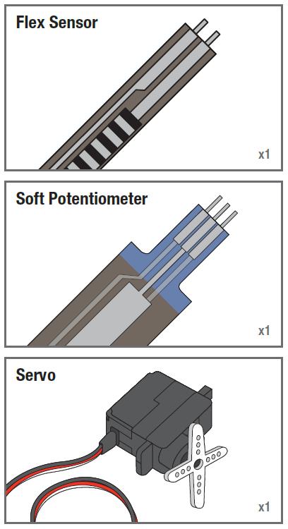
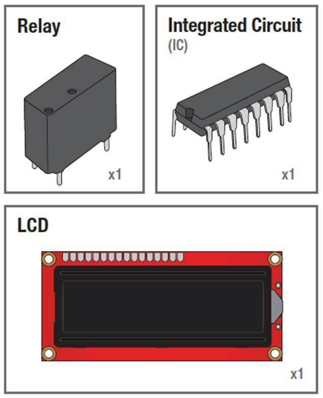
3 Components Name Image Type Function Notes Push Button Digital Input Switch - Closes or opens circuit Trim potentiometer Polarized, needs resistor Analog Input Variable resistor Also called a Trimpot. Photoresistor Analog Input Light Dependent Resistor (LDR) Relay Digital Output Switch driven by a small signal Temp Sensor Analog Input Temp Dependent Resistor Flex Sensor Analog Input Variable resistor Resistance varies with light. Used to control larger voltages Soft Trimpot Analog Input Variable resistor Careful of shorts RGB LED Dig & Analog Output 16,777,216 different colors Ooh... So pretty. 3
4 Components 4


5 INPUT vs. OUTPUT Inputs is a signal / information going into the board. Output is any signal exiting the board. Examples: Buttons Switches, Light Sensors, Flex Sensors, Humidity Sensors, Temperature Sensors 5
6 Electronics Basic Concept Ohms Law Voltage Current Resistance Using a Multi-meter 6
7 Ohm s Law Voltage V Defined as the amount of potential energy in a circuit. Units: Volts (V) Current The rate of charge flow in a circuit. Units: Amperes (A) I Resistance R 7
8 Current Flow Analogy High Current Low Current 8


9 Voltage Analogy Water Tower Water Tower V V More Energy == Higher Voltage Less Energy == Lower Voltage 9


10 Resistance Analogy Water Tower Water Tower V Big Pipe == Lower Resistance Small Pipe == Higher Resistance 10


11 Continuity Circuit? An Electrical Circuit must have a continuous LOOP from Power (V cc ) to Ground (GND). Continuity is important to make portions of circuits are connect. Continuity is the simplest and possibly the most important setting on your multi-meter. Sometimes we call this ringing out a circuit. 11


12 Measuring Electricity Voltage Voltage is a measure of potential electrical energy. A voltage is also called a potential difference it is measured between two points in a circuit across a device. 12


13 Measuring Electricity -- Current Current is the measure of the rate of charge flow. For Electrical Engineers we consider this to be the movement of electrons. In order to measure this you must break the circuit or insert the meter in-line (series). 13

14 Measuring Electricity -- Resistance Resistance is the measure of how much opposition to current flow is in a circuit. Components should be removed entirely from the circuit to measure resistance. Note the settings on the multi-meter. Make sure that you are set for the appropriate range. Resistance settings 14
15 Analog Input Arduino uses a 10-bit A/D Converter: this means that you get input values from 0 to V 0 5 V 1023 Ex: int sensorvalue = analogread(a0); 15

16 Analog Input Voltage Based Sensors 3 Pin Potentiometer(var. resistor) Voltage Divider Circuit 10k 16
17 Analog Input 2 Pin Analog Sensors ( var. resistor) Take two sensors -- Use the Serial Monitor and find the range of input values you get for each sensor. MaxAnalogRead = MinAnalogRead = 17
18 Reading analog inputs and scaling map(value, fromlow, fromhigh, tolow, tohigh) const int potpin = 0; // select the input pin for the potentiometer void loop() { int val; // The value coming from the sensor int percent; // The mapped value val = analogread(potpin); // read the voltage on the pot (val 0 to 1023) percent = map(val,0,1023,0,100); // percent will range from 0 to
19 Analog Input Measuring Temperature const int inpin = 0; void loop() { int value = analogread(inpin); float millivolts = (value / ) * 3300; float celsius = millivolts / 10; delay(1000); // analog pin //3.3V analog input // sensor output is 10mV per //degree Celsius // wait for one second 19


20 Analog Output Analog vs. Digital To create an analog signal, the microcontroller uses a technique called PWM. By varying the duty cycle, we can mimic an average analog voltage. Pulse Width Modulation (PWM) 20

21 Analog Output Fading analogwrite(pin, val); Pin: refers to the OUTPUT pin (limited to pins 3, 5, 6, 9, 10, 11.) denoted by a ~ symbol Val (Duty Cycle): (0 255). 21
22 Fading in and Fading Out LED int ledpin = 9; // LED connected to digital pin 9 void setup() { void loop() { for(int fadevalue = 0 ; fadevalue <= 255; fadevalue +=5) { analogwrite(ledpin, fadevalue); // sets the value (range from 0 to 255): delay(30); for(int fadevalue = 255 ; fadevalue >= 0; fadevalue -=5) { analogwrite(ledpin, fadevalue); // sets the value (range from 0 to 255): delay(30); 22

23 Analog Output Color Mixing/Tri-color LED R G B this is a standard Common Cathode LED This means the negative side of the LED is all tied to Ground. 23

24 Analog Output RGB LED Note: The longest leg of the RGB LED is the Common Cathode. This goes to GND. Use pins 5, 6, & 9 24
25 Using RGB LED int redpin = 5; int greenpin = 6; int bluepin = 9; void setup() { pinmode(redpin, OUTPUT); pinmode(greenpin, OUTPUT); pinmode(bluepin, OUTPUT); 25
26 RGB LED Color Mixing void loop() { analogwrite(redpin, 255); analogwrite (greenpin, 255); analogwrite (bluepin, 255); 26


27 Digital Input Digital Sensors (Switches) Pull-up Resistor Signal is always either HIGH (On) 5v or LOW (Off) 0v. In Arduino, open up: File Examples 02.Digital Button to Digital Pin 2 27


28 Add LED to Pin 13 28
29 Button & LED int buttonpin = 2; int ledpin = 13; int buttonstate = 0; void setup() { pinmode(ledpin, OUTPUT); pinmode(buttonpin, INPUT); void loop() { buttonstate = digitalread(buttonpin); if (buttonstate == HIGH) { digitalwrite(ledpin, HIGH); // the number of the pushbutton pin // the number of the LED pin // variable for reading the pushbutton status // initialize the LED pin as an output: // initialize the pushbutton pin as an input: // read the state of the pushbutton value: // check if the pushbutton is pressed. // turn LED on: else { digitalwrite(ledpin, LOW); // turn LED off: 29
30 Button & LED The problem with the last program is that the switch has to remain pressed in order for the LED to turn on. We want the LED to change state when we press the button and to stay in the new state when the button is released 30
31 Button & LED int buttonpin = 2; int ledpin = 13; int buttonstate = 0; int lastledstate = 0; void setup() { pinmode(buttonpin, INPUT); pinmode(ledpin, OUTPUT); void loop() { buttonstate = digitalread(buttonpin); // the pin that the pushbutton is attached to // the pin that the LED is attached to // current state of the button // previous state of the button // initialize the button pin as a input: // initialize the LED as an output: // read the pushbutton input pin: if (buttonstate == HIGH) { if (lastledstate == HIGH) { digitalwrite(ledpin, LOW); lastledstate = LOW; else { digitalwrite(ledpin, HIGH); lastledstate = HIGH; while(buttonstate == HIGH){ buttonstate = digitalread(buttonpin); ; delay(250); // Determine if button State is HIGH // if the current state is HIGH then turn LED off // if the current state is LOW then turn LED on // read the pushbutton input pin: 31
 light radiating from objects in its field of view. 32")
32 Digital Input PIR motion sensors A passive infrared sensor (PIR sensor) is an electronic sensor that measures infrared (IR) light radiating from objects in its field of view. 32
33 Using PIR motion sensors const int ledpin = 7; // pin for the LED const int inputpin = 2; // input pin (for the PIR sensor) void setup() { pinmode(ledpin, OUTPUT); // declare LED as output pinmode(inputpin, INPUT); // declare pushbutton as input void loop(){ int val = digitalread(inputpin); // read input value if (val == HIGH) // check if the input is HIGH { digitalwrite(ledpin, HIGH); // turn LED on if motion detected delay(500); digitalwrite(ledpin, LOW); // turn LED off 33

34 Digital Output LED Move the green wire to pin 13 (or any other Digital I/O pin on the Arduino board. 34


35 Digital Output Add an External LED to Pin 13 File > Examples > Digital > Blink LED s have polarity Negative indicated by flat side of the housing and a short leg 35
36 Using the LED int ledpin = 13; // LED connected to digital pin 13 // The setup() method runs once, when the sketch starts void setup() { // initialize the digital pin as an output: pinmode(ledpin, OUTPUT); // the loop() method runs over and over again, // as long as the Arduino has power void loop() { digitalwrite(ledpin, HIGH); delay(1000); digitalwrite(ledpin, LOW); delay(1000); // set the LED on // wait for a second // set the LED off // wait for a second 36

37 Digital Output/Digital Input Ultrasonic Sensor Active ultrasonic sensors generate high frequency sound waves and evaluate the echo which is received back by the sensor, measuring the time interval between sending the signal and receiving the echo to determine the distance to an object. It has four wires: 1.Vcc connect to 5V dc 2.Trigger----pulse input that triggers the sensor 3.Echo----- indicates the reception of echo from the target 4.Gnd Ground 37
38 Ultrasonic Sensor Provide TRIGGER signal, at least 10μS High Level (5V) pulse. The module will automatically transmit eight 40KHz ultrasonic burst. If there is an obstacle in-front of the module, it will reflect the ultrasonic burst. If the signal is back, ECHO output of the sensor will be in HIGH state (5V) for a duration of time taken for sending and receiving ultrasonic burst. Pulse width ranges from about 150μS to 25mS and if no obstacle is detected, the echo pulse width will be about 38ms. Range = high level time * velocity (340M/S) / 2 38
39 Timing Diagram 39
40 #include <NewPing.h> #define TRIGGER_PIN 12 Using ultrasonic sensors // Arduino pin tied to trigger pin on the ultrasonic sensor. #define ECHO_PIN 11 // Arduino pin tied to echo pin on the ultrasonic sensor. #define MAX_DISTANCE 200 // Maximum distance we want to ping for (in centimeters). //Maximum sensor distance is rated at cm. NewPing sonar(trigger_pin, ECHO_PIN, MAX_DISTANCE); // NewPing setup of pins //and maximum //distance. void setup() { Serial.begin(115200); // Open serial monitor at baud to see ping results. void loop() { delay(50); unsigned int us = sonar.ping(); Serial.print("Ping: "); // Send ping, get ping time in microseconds (us). Serial.print(uS / US_ROUNDTRIP_CM); // Convert ping time to distance and print result //(0 = outside set distance range, no ping echo) Serial.println("cm"); 40
41 Digital Output Sound-Piezo A Piezo is an electronic piece that converts electricity energy to sound. It is a digital output device. You can make white noise or even exact musical notes ( frequencies for musical notes) based on the duration that you iterate between HIGH and LOW signals. A Piezo is a directional piece, meaning that it has a positive and negative pole. The positive pole should be connected to the digital output pin that you allocate to control the piezo and the negative pole should be connected to Ground pin 41
42 Digital Output Piezo //connect piezo to pin 13 and ground int freqs[] = { 1915, 1700, 1519, 1432, 1275, 1136, 1014, 956; //string tones[] = {"do", "re", "mi", "fa","sol"," la", "si", "do"; void setup(){ pinmode(13,output); void loop(){ for(int i=0;i<8;i++){//iterating through notes for(int j=0;j<1000;j++){//the time span that each note is being played digitalwrite(13,high); delaymicroseconds(freqs[i]); digitalwrite(13,low); delaymicroseconds(freqs[i]); 42
 is set to the digital")
43 DigitalOutput 1. Servo Motor Servo Motors are electronic devices that convert digital signal to rotational movement. It has three connections: the black is ground, the red is connected to 5V, and the white (yellow wire) is set to the digital pin. 43
44 DigitalOutput Using Servo Motor #include <Servo.h> Servo myservo; int pos = 0; // create servo object to control a servo // variable to store the servo position void setup() { myservo.attach(9); // attaches the servo on pin 9 to the servo object void loop() { for(pos = 0; pos <= 180; pos += 1) { myservo.write(pos); delay(15); for(pos = 180; pos>=0; pos-=1) { myservo.write(pos); delay(15); // goes from 0 degrees to 180 degrees in steps of 1 degree // tell servo to go to position in variable 'pos' // waits 15ms for the servo to reach the position // goes from 180 degrees to 0 degrees // tell servo to go to position in variable 'pos' // waits 15ms for the servo to reach the position 44
{ pinmode(13, OUTPUT); // Specify Arduino Pin number and output/input mode void loop(){ digitalwrite(13, HIGH); // Turn on Pin 13 sending a HIGH")
45 Digital Output 2. DC Motor // Connect to Pin 13 and Ground void setup(){ pinmode(13, OUTPUT); // Specify Arduino Pin number and output/input mode void loop(){ digitalwrite(13, HIGH); // Turn on Pin 13 sending a HIGH Signal delay(1000); // Wait for one second digitalwrite(13, LOW); // Turn off Pin 13 sending a LOW Signal delay(3000); // Wait for Three second Code for Rotation/No Rotation // Connect to Pin 13 and 12 void setup(){ pinmode(13, OUTPUT); // Specify Arduino Pin number and output/input mode pinmode(12, OUTPUT); void loop(){ digitalwrite(13, HIGH); // Turn on Pin 13 sending a HIGH Signal digitalwrite(12, LOW); //Make Pin 12 a Ground delay(1000); // Wait for one second digitalwrite(13, LOW); // Make Pin 13 a Ground digitalwrite(12, HIGH); // Turn on Pin 12 sending a HIGH Signal delay(3000); // Wait for Three second Code for CW and CCW Rotation 45


46 Digital Output 3. Stepper Motor Stepper motors translate digital switching sequences into motion. They are used in a variety of applications requiring precise motions under computer control. Unlike ordinary dc motors, which spin freely when power is applied, steppers require that their power source be continuously pulsed in specific patterns. These patterns, or step sequences, determine the speed and direction of a stepper s motion. For each pulse or step input, the stepper motor rotates a fixed angular increment; typically 1.8 or 7.5 degrees. 46

47 Stepper Motor The most common stepper is the four-coil unipolar variety. These are called unipolar because they require only that their coils be driven on and off. Bipolar steppers require that the polarity of power to the coils be reversed. The normal stepping sequence for four-coil unipolar steppers appears in the figure. If you run the stepping sequence in the figure forward, the stepper rotates clockwise; run it backward, and the stepper rotates counterclockwise. The motor s speed depends on how fast the controller (L293D, ULN2003/2004) runs through the step sequence. At any time the controller can stop in mid sequence. 47
48 void setup(){ pinmode(2,output); pinmode(3,output); pinmode(4,output); pinmode(5,output); void loop(){ // Pause between the types that determines the speed int stepperspeed=200;// Change to change speed int dir=1;// change to -1 to change direction if (dir==1){ //Running Clockwise digitalwrite(2,high);//step 1 digitalwrite(3,low); digitalwrite(4,high); digitalwrite(5,low); delay(stepperspeed);// Pause between the types that determines the speed digitalwrite(2,high);//step 2 digitalwrite(3,low); digitalwrite(4,low); digitalwrite(5,high); delay(stepperspeed);// Pause between the types that determines the speed digitalwrite(2,low);//step 3 digitalwrite(3,high); digitalwrite(4,low); digitalwrite(5,high); delay(stepperspeed);// Pause between the types that determines the speed digitalwrite(2,low);//step 4 digitalwrite(3,high); digitalwrite(4,high); digitalwrite(5,low); delay(stepperspeed);// Pause between the types that determines the speed if (dir==-1){ //Running CounterClockwise digitalwrite(2,low);//step 4 digitalwrite(3,high); digitalwrite(4,high); digitalwrite(5,low); delay(stepperspeed);// Pause between the types that determines the speed digitalwrite(2,low);//step 3 digitalwrite(3,high); digitalwrite(4,low); digitalwrite(5,high); delay(stepperspeed);// Pause between the types that determines the speed digitalwrite(2,high);//step 2 digitalwrite(3,low); digitalwrite(4,low); digitalwrite(5,high); delay(stepperspeed);// Pause between the types that determines the speed digitalwrite(2,high);//step1 digitalwrite(3,low); digitalwrite(4,high); digitalwrite(5,low); delay(stepperspeed);// Pause between the types that determines the speed Stepper Moto Direction and Speed 48

 to")
49 Driving Motors or other High Current Loads NPN Transistor (Common Emitter Amplifier Circuit) to Digital Pin 9 49
{ pinmode(13, OUTPUT); // Specify Arduino Pin number and output/input mode void loop(){")
; // Wait for Three second Externally Powered Device External Power 3v-220v")
50 Digital Output Controling any Electrical Device with any power needs using a relay Externally Powered Device // Connect to Pin 13 and Ground void setup(){ pinmode(13, OUTPUT); // Specify Arduino Pin number and output/input mode void loop(){ digitalwrite(13, HIGH); // Turn on Pin 13 sending a HIGH Signal delay(1000); // Wait for one second digitalwrite(13, LOW); // Turn off Pin 13 sending a LOW Signal delay(3000); // Wait for Three second Externally Powered Device External Power 3v-220v Control Pin 50
Disclaimer. Arduino Hands-On 2 CS5968 / ART4455 9/1/10. ! Many of these slides are mine. ! But, some are stolen from various places on the web
 Arduino Hands-On 2 CS5968 / ART4455 Disclaimer! Many of these slides are mine! But, some are stolen from various places on the web! todbot.com Bionic Arduino and Spooky Arduino class notes from Tod E.Kurt!
Arduino Digital Out_QUICK RECAP
 Arduino Digital Out_QUICK RECAP BLINK File> Examples>Digital>Blink int ledpin = 13; // LED connected to digital pin 13 // The setup() method runs once, when the sketch starts void setup() // initialize
Assignments from last week
 Assignments from last week Review LED flasher kits Review protoshields Need more soldering practice (see below)? http://www.allelectronics.com/make-a-store/category/305/kits/1.html http://www.mpja.com/departments.asp?dept=61
Arduino. AS220 Workshop. Part II Interactive Design with advanced Transducers Lutz Hamel
 AS220 Workshop Part II Interactive Design with advanced Transducers Lutz Hamel hamel@cs.uri.edu www.cs.uri.edu/~hamel/as220 How we see the computer Image source: Considering the Body, Kate Hartman, 2008.
HAW-Arduino. Sensors and Arduino F. Schubert HAW - Arduino 1
 HAW-Arduino Sensors and Arduino 14.10.2010 F. Schubert HAW - Arduino 1 Content of the USB-Stick PDF-File of this script Arduino-software Source-codes Helpful links 14.10.2010 HAW - Arduino 2 Report for
SCHOOL OF TECHNOLOGY AND PUBLIC MANAGEMENT ENGINEERING TECHNOLOGY DEPARTMENT
 SCHOOL OF TECHNOLOGY AND PUBLIC MANAGEMENT ENGINEERING TECHNOLOGY DEPARTMENT Course ENGT 3260 Microcontrollers Summer III 2015 Instructor: Dr. Maged Mikhail Project Report Submitted By: Nicole Kirch 7/10/2015
.:Twisting:..:Potentiometers:.
 CIRC-08.:Twisting:..:Potentiometers:. WHAT WE RE DOING: Along with the digital pins, the also has 6 pins which can be used for analog input. These inputs take a voltage (from 0 to 5 volts) and convert
1. Introduction to Analog I/O
 EduCake Analog I/O Intro 1. Introduction to Analog I/O In previous chapter, we introduced the 86Duino EduCake, talked about EduCake s I/O features and specification, the development IDE and multiple examples
Mechatronics Engineering and Automation Faculty of Engineering, Ain Shams University MCT-151, Spring 2015 Lab-4: Electric Actuators
 Mechatronics Engineering and Automation Faculty of Engineering, Ain Shams University MCT-151, Spring 2015 Lab-4: Electric Actuators Ahmed Okasha, Assistant Lecturer okasha1st@gmail.com Objective Have a
Computational Crafting with Arduino. Christopher Michaud Marist School ECEP Programs, Georgia Tech
 Computational Crafting with Arduino Christopher Michaud Marist School ECEP Programs, Georgia Tech Introduction What do you want to learn and do today? Goals with Arduino / Computational Crafting Purpose
Basics before Migtrating to Arduino
 Basics before Migtrating to Arduino Who is this for? Written by Storming Robots Last update: Oct 11 th, 2013 This document is meant for preparing students who have already good amount of programming knowledge,
Sten-Bot Robot Kit Stensat Group LLC, Copyright 2013
 Sten-Bot Robot Kit Stensat Group LLC, Copyright 2013 Legal Stuff Stensat Group LLC assumes no responsibility and/or liability for the use of the kit and documentation. There is a 90 day warranty for the
Experiment 1 Identification of Components and Breadboard Realization
 Experiment 1 Identification of Components and Breadboard Realization Aim: Introduction to the lab and identification of various components and realization using bread board. Hardware/Software Required:
100UF CAPACITOR POTENTIOMETER SERVO MOTOR MOTOR ARM. MALE HEADER PIN (3 pins) INGREDIENTS
 INGREDIENTS") 05 POTENTIOMETER SERVO MOTOR MOTOR ARM 100UF CAPACITOR MALE HEADER PIN (3 pins) INGREDIENTS 63 MOOD CUE USE A SERVO MOTOR TO MAKE A MECHANICAL GAUGE TO POINT OUT WHAT SORT OF MOOD YOU RE IN THAT DAY Discover:
05 POTENTIOMETER SERVO MOTOR MOTOR ARM 100UF CAPACITOR MALE HEADER PIN (3 pins) INGREDIENTS 63 MOOD CUE USE A SERVO MOTOR TO MAKE A MECHANICAL GAUGE TO POINT OUT WHAT SORT OF MOOD YOU RE IN THAT DAY Discover:
Introduction to. An Open-Source Prototyping Platform. Hans-Petter Halvorsen
 Introduction to An Open-Source Prototyping Platform Hans-Petter Halvorsen Contents 1.Overview 2.Installation 3.Arduino Starter Kit 4.Arduino TinkerKit 5.Arduino Examples 6.LabVIEW Interface for Arduino
MICROCONTROLLERS BASIC INPUTS and OUTPUTS (I/O)
") PH-315 Portland State University MICROCONTROLLERS BASIC INPUTS and OUTPUTS (I/O) ABSTRACT A microcontroller is an integrated circuit containing a processor and programmable read-only memory, 1 which is
PH-315 Portland State University MICROCONTROLLERS BASIC INPUTS and OUTPUTS (I/O) ABSTRACT A microcontroller is an integrated circuit containing a processor and programmable read-only memory, 1 which is
Coding with Arduino to operate the prosthetic arm
 Setup Board Install FTDI Drivers This is so that your RedBoard will be able to communicate with your computer. If you have Windows 8 or above you might already have the drivers. 1. Download the FTDI driver
Lecture 4: Basic Electronics. Lecture 4 Brief Introduction to Electronics and the Arduino
 Lecture 4: Basic Electronics Lecture 4 Page: 1 Brief Introduction to Electronics and the Arduino colintan@nus.edu.sg Lecture 4: Basic Electronics Page: 2 Objectives of this Lecture By the end of today
Sidekick Basic Kit for Arduino V2 Introduction
 Sidekick Basic Kit for Arduino V2 Introduction The Arduino Sidekick Basic Kit is designed to be used with your Arduino / Seeeduino / Seeeduino ADK / Maple Lilypad or any MCU board. It contains everything
Learning Objectives. References 10/26/11. Using servos with an Arduino. EAS 199A Fall 2011
 Using servos with an Arduino EAS 199A Fall 2011 Learning Objectives Be able to identify characteristics that distinguish a servo and a DC motor Be able to describe the difference a conventional servo and
Servo Sweep. Learn to make a regular Servo move in a sweeping motion.
 Servo Sweep Learn to make a regular Servo move in a sweeping motion. We have seen how to control a Servo and also how to make an LED Fade on and off. This activity will teach you how to make a regular
Using Servos with an Arduino
 Using Servos with an Arduino ME 120 Mechanical and Materials Engineering Portland State University http://web.cecs.pdx.edu/~me120 Learning Objectives Be able to identify characteristics that distinguish
Yihao Qian Team A: Aware Teammates: Amit Agarwal Harry Golash Menghan Zhang Zihao (Theo) Zhang ILR01 Oct.14, 2016
 Zhang ILR01 Oct.14, 2016") Yihao Qian Team A: Aware Teammates: Amit Agarwal Harry Golash Menghan Zhang Zihao (Theo) Zhang ILR01 Oct.14, 2016 Individual Progress For sensors and motors lab, I was in charge of the servo and force
Yihao Qian Team A: Aware Teammates: Amit Agarwal Harry Golash Menghan Zhang Zihao (Theo) Zhang ILR01 Oct.14, 2016 Individual Progress For sensors and motors lab, I was in charge of the servo and force
Design with Microprocessors Year III Computer Science 1-st Semester
 Design with Microprocessors Year III Computer Science 1-st Semester Lecture 9: Microcontroller based applications: usage of sensors and actuators (motors) DC motor control Diligent MT motor/gearbox 1/19
Arduino and Servo Motor
 Arduino and Servo Motor 1. Basics of the Arduino Board and Arduino a. Arduino is a mini computer that can input and output data using the digital and analog pins b. Arduino Shield: mounts on top of Arduino
Arduino Advanced Projects
 Arduino Advanced Projects Created as a companion manual to the Toronto Public Library Arduino Kits. Arduino Advanced Projects Copyright 2017 Toronto Public Library. All rights reserved. Published by the
Sten BOT Robot Kit 1 Stensat Group LLC, Copyright 2016
 StenBOT Robot Kit Stensat Group LLC, Copyright 2016 1 Legal Stuff Stensat Group LLC assumes no responsibility and/or liability for the use of the kit and documentation. There is a 90 day warranty for the
CONSTRUCTION GUIDE IR Alarm. Robobox. Level I
 CONSTRUCTION GUIDE Robobox Level I This month s montage is an that will allow you to detect any intruder. When a movement is detected, the alarm will turn its LEDs on and buzz to a personalized tune. 1X
Experiment 1: Robot Moves in 3ft squared makes sound and
 Experiment 1: Robot Moves in 3ft squared makes sound and turns on an LED at each turn then stop where it started. Edited: 9-7-2015 Purpose: Press a button, make a sound and wait 3 seconds before starting
Robotic Arm Assembly Instructions
 Robotic Arm Assembly Instructions Last Revised: 11 January 2017 Part A: First follow the instructions: http://www.robotshop.com/media/files/zip2/rbmea-02_-_documentation_1.zip While assembling the servos:
Introduction: Components used:
 Introduction: As, this robotic arm is automatic in a way that it can decides where to move and when to move, therefore it works in a closed loop system where sensor detects if there is any object in a
Arduino Control of Tetrix Prizm Robotics. Motors and Servos Introduction to Robotics and Engineering Marist School
 Arduino Control of Tetrix Prizm Robotics Motors and Servos Introduction to Robotics and Engineering Marist School Motor or Servo? Motor Faster revolution but less Power Tetrix 12 Volt DC motors have a
Attribution Thank you to Arduino and SparkFun for open source access to reference materials.
 Attribution Thank you to Arduino and SparkFun for open source access to reference materials. Contents Parts Reference... 1 Installing Arduino... 7 Unit 1: LEDs, Resistors, & Buttons... 7 1.1 Blink (Hello
6Circuit Worksheets SIK BINDER //93
 6Circuit Worksheets SIK BINDER //93 Tier 1 Difficulty Circuit #1 Blink LED Ohm s Law: V = I * R I = V / R R = V / I How is this circuit, or a circuit like it, used in everyday life? Provide at least three
Operating Mode: Serial; (PWM) passive control mode; Autonomous Mode; On/OFF Mode
 passive control mode; Autonomous Mode; On/OFF Mode") RB-Dfr-11 DFRobot URM V3.2 Ultrasonic Sensor URM37 V3.2 Ultrasonic Sensor uses an industrial level AVR processor as the main processing unit. It comes with a temperature correction which is very unique
RB-Dfr-11 DFRobot URM V3.2 Ultrasonic Sensor URM37 V3.2 Ultrasonic Sensor uses an industrial level AVR processor as the main processing unit. It comes with a temperature correction which is very unique
NAMASKAR ROBOT-WHICH PROVIDES SERVICE
 Int. J. Elec&Electr.Eng&Telecoms. 2014 V Sai Krishna and R Sunitha, 2014 Research Paper ISSN 2319 2518 www.ijeetc.com Vol. 3, No. 1, January 2014 2014 IJEETC. All Rights Reserved NAMASKAR ROBOT-WHICH PROVIDES
Embedded Controls Final Project. Tom Hall EE /07/2011
 Embedded Controls Final Project Tom Hall EE 554 12/07/2011 Introduction: The given task was to design a system that: -Uses at least one actuator and one sensor -Determine a controlled variable and suitable
CONSTRUCTION GUIDE Capacitor, Transistor & Motorbike. Robobox. Level VII
 CONSTRUCTION GUIDE Capacitor, Transistor & Motorbike Robobox Level VII Capacitor, Transistor & Motorbike In this box, we will understand in more detail the operation of DC motors, transistors and capacitor.
CMSC838. Tangible Interactive Assistant Professor Computer Science. Week 11 Lecture 20 April 9, 2015 Motors
 CMSC838 Tangible Interactive Computing Week 11 Lecture 20 April 9, 2015 Motors Human Computer Interaction Laboratory @jonfroehlich Assistant Professor Computer Science TODAY S LEARNING GOALS 1. Learn about
ABCs of Arduino. Kurt Turchan -
 ABCs of Arduino Kurt Turchan - kurt@trailpeak.com Bio: Kurt is a web designer (java/php/ui-jquery), project manager, instructor (PHP/HTML/...), and arduino enthusiast, Kurt is founder of www.trailpeak.com
Arduino Application: Speed control of small DC Motors
 Arduino Application: Speed control of small DC Motors ME 120 Mechanical and Materials Engineering Portland State University http://web.cecs.pdx.edu/~me120 Learning Objectives Be able to describe the use
Lab 5: Arduino Uno Microcontroller Innovation Fellows Program Bootcamp Prof. Steven S. Saliterman
 Lab 5: Arduino Uno Microcontroller Innovation Fellows Program Bootcamp Prof. Steven S. Saliterman Exercise 5-1: Familiarization with Lab Box Contents Objective: To review the items required for working
The µbotino Microcontroller Board
 The µbotino Microcontroller Board by Ro-Bot-X Designs Introduction. The µbotino Microcontroller Board is an Arduino compatible board for small robots. The 5x5cm (2x2 ) size and the built in 3 pin connectors
Sensor and. Motor Control Lab. Abhishek Bhatia. Individual Lab Report #1
 Sensor and 10/16/2015 Motor Control Lab Individual Lab Report #1 Abhishek Bhatia Team D: Team HARP (Human Assistive Robotic Picker) Teammates: Alex Brinkman, Feroze Naina, Lekha Mohan, Rick Shanor I. Individual
RGB LED Strips. Created by lady ada. Last updated on :21:20 PM UTC
 RGB LED Strips Created by lady ada Last updated on 2017-11-26 10:21:20 PM UTC Guide Contents Guide Contents Overview Schematic Current Draw Wiring Usage Arduino Code CircuitPython Code 2 3 5 6 7 10 12
Analog Feedback Servos
 Analog Feedback Servos Created by Bill Earl Last updated on 2018-01-21 07:07:32 PM UTC Guide Contents Guide Contents About Servos and Feedback What is a Servo? Open and Closed Loops Using Feedback Reading
CONSTRUCTION GUIDE Robotic Arm. Robobox. Level II
 CONSTRUCTION GUIDE Robotic Arm Robobox Level II Robotic Arm This month s robot is a robotic arm with two degrees of freedom that will teach you how to use motors. You will then be able to move the arm
The Motor sketch. One Direction ON-OFF DC Motor
 One Direction ON-OFF DC Motor The DC motor in your Arduino kit is the most basic of electric motors and is used in all types of hobby electronics. When current is passed through, it spins continuously
J. La Favre Using Arduino with Raspberry Pi February 7, 2018
 As you have already discovered, the Raspberry Pi is a very capable digital device. Nevertheless, it does have some weaknesses. For example, it does not produce a clean pulse width modulation output (unless
Available online Journal of Scientific and Engineering Research, 2018, 5(4): Research Article
: Research Article") Available online www.jsaer.com, 2018, 5(4):341-349 Research Article ISSN: 2394-2630 CODEN(USA): JSERBR Arduino Based door Automation System Using Ultrasonic Sensor and Servo Motor Orji EZ*, Oleka CV, Nduanya
Available online www.jsaer.com, 2018, 5(4):341-349 Research Article ISSN: 2394-2630 CODEN(USA): JSERBR Arduino Based door Automation System Using Ultrasonic Sensor and Servo Motor Orji EZ*, Oleka CV, Nduanya
EEE3410 Microcontroller Applications Department of Electrical Engineering Lecture 11 Motor Control
 EEE34 Microcontroller Applications Department of Electrical Engineering Lecture Motor Control Week 3 EEE34 Microcontroller Applications In this Lecture. Interface 85 with the following output Devices Optoisolator
4WD Mobile Platform SKU:ROB0022
 4WD Mobile Platform SKU:ROB0022 Contents [hide] 1 Function Introduction 1.1 STEP1: Assemble Robot 1.2 STEP2: Debug Motor 1.3 STEP3:Install Upper Plate 1.4 STEP4: Debug Ultrasonic Sensor and Servo 1.5 STEP5:
Using Transistors and Driving Motors
 Chapter 4 Using Transistors and Driving Motors Parts You ll Need for This Chapter: Arduino Uno USB cable 9V battery 9V battery clip 5V L4940V5 linear regulator 22uF electrolytic capacitor.1uf electrolytic
SMART Funded by The National Science Foundation
 Lecture 5 Capacitors 1 Store electric charge Consists of two plates of a conducting material separated by a space filled by an insulator Measured in units called farads, F Capacitors 2 Mylar Ceramic Electrolytic
HOW TO BUILD A CAR PARK WITH INTEL GALILEO!
 HOW TO BUILD A CAR PARK WITH INTEL GALILEO! A step by step tutorial to build, in a very simple way, a funny car park with automatic barrier and display counter with your Intel Galileo!» Recommended age
You'll create a lamp that turns a light on and off when you touch a piece of conductive material
 TOUCHY-FEELY LAMP You'll create a lamp that turns a light on and off when you touch a piece of conductive material Discover : installing third party libraries, creating a touch sensor Time : 5 minutes
Lesson4 Obstacle avoidance car
 Lesson4 Obstacle avoidance car 1 Points of this section The joy of learning, is not just know how to control your car, but also know how to protect your car. So, make you car far away from collision. Learning
CURIE Academy, Summer 2014 Lab 2: Computer Engineering Software Perspective Sign-Off Sheet
 Lab : Computer Engineering Software Perspective Sign-Off Sheet NAME: NAME: DATE: Sign-Off Milestone TA Initials Part 1.A Part 1.B Part.A Part.B Part.C Part 3.A Part 3.B Part 3.C Test Simple Addition Program
URM37 V3.2 Ultrasonic Sensor (SKU:SEN0001)
") URM37 V3.2 Ultrasonic Sensor (SKU:SEN0001) From Robot Wiki Contents 1 Introduction 2 Specification 2.1 Compare with other ultrasonic sensor 3 Hardware requierments 4 Tools used 5 Software 6 Working Mode
URM37 V3.2 Ultrasonic Sensor (SKU:SEN0001) From Robot Wiki Contents 1 Introduction 2 Specification 2.1 Compare with other ultrasonic sensor 3 Hardware requierments 4 Tools used 5 Software 6 Working Mode
Objectives: Learn what an Arduino is and what it can do Learn what an LED is and how to use it Be able to wire and program an LED to blink
 Objectives: Learn what an Arduino is and what it can do Learn what an LED is and how to use it Be able to wire and program an LED to blink By the end of this session: You will know how to use an Arduino
PHYSICS 124 PROJECT REPORT Kayleigh Brook and Zulfar Ghulam-Jelani
 PHYSICS 124 PROJECT REPORT Kayleigh Brook and Zulfar Ghulam-Jelani MOTIVATION AND OVERALL CONCEPT The ability to track eye movements in a quantitative way has many applications, including psychological
FABO ACADEMY X ELECTRONIC DESIGN
 ELECTRONIC DESIGN MAKE A DEVICE WITH INPUT & OUTPUT The Shanghaino can be programmed to use many input and output devices (a motor, a light sensor, etc) uploading an instruction code (a program) to it
C++ PROGRAM FOR DRIVING OF AN AGRICOL ROBOT
 Annals of the University of Petroşani, Mechanical Engineering, 14 (2012), 11-19 11 C++ PROGRAM FOR DRIVING OF AN AGRICOL ROBOT STELIAN-VALENTIN CASAVELA 1 Abstract: This robot is projected to participate
Figure 1. Digilent DC Motor
 Laboratory 9 - Usage of DC- and servo-motors The current laboratory describes the usage of DC and servomotors 1. DC motors Figure 1. Digilent DC Motor Classical DC motors are converting electrical energy
Two Hour Robot. Lets build a Robot.
 Lets build a Robot. Our robot will use an ultrasonic sensor and servos to navigate it s way around a maze. We will be making 2 voltage circuits : A 5 Volt for our ultrasonic sensor, sound and lights powered
Workshops Elisava Introduction to programming and electronics (Scratch & Arduino)
") Workshops Elisava 2011 Introduction to programming and electronics (Scratch & Arduino) What is programming? Make an algorithm to do something in a specific language programming. Algorithm: a procedure
Workshops Elisava 2011 Introduction to programming and electronics (Scratch & Arduino) What is programming? Make an algorithm to do something in a specific language programming. Algorithm: a procedure
LED + Servo 2 devices, 1 Arduino
 LED + Servo 2 devices, 1 Arduino Learn to connect and write code to control both a Servo and an LED at the same time. Many students who come through the lab ask if they can use both an LED and a Servo
ME 2110 Controller Box Manual. Version 2.3
 ME 2110 Controller Box Manual Version 2.3 I. Introduction to the ME 2110 Controller Box A. The Controller Box B. The Programming Editor & Writing PBASIC Programs C. Debugging Controller Box Problems II.
.:Getting Started:..:(Blinking LED):.
:.") CIRC-01.:Getting Started:..:(Blinking LED):. WHAT WE RE DOING: LEDs (light emitting diodes) are used in all sorts of clever things which is why we have included them in this kit. We will start off with
CIRC-01.:Getting Started:..:(Blinking LED):. WHAT WE RE DOING: LEDs (light emitting diodes) are used in all sorts of clever things which is why we have included them in this kit. We will start off with
The Robot Builder's Shield for Arduino
 The Robot Builder's Shield for Arduino by Ro-Bot-X Designs Introduction. The Robot Builder's Shield for Arduino was especially designed to make building robots with Arduino easy. The built in dual motors
FC Series Signal Conditioners
 FC Series Signal Conditioners FC-33 DC Selectable Signal Conditioner with 3-way isolation Field configurable input and output ranges of 0-5V, 0-10 V, 0-20 ma and 4-20 ma with 1500 VDC isolation between
Assembly Language. Topic 14 Motion Control. Stepper and Servo Motors
 Assembly Language Topic 14 Motion Control Stepper and Servo Motors Objectives To gain an understanding of the operation of a stepper motor To develop a means to control a stepper motor To gain an understanding
02 Digital Input and Output
 week 02 Digital Input and Output RGB LEDs fade with PWM 1 Microcontrollers utput ransducers actuators (e.g., motors, buzzers) Arduino nput ransducers sensors (e.g., switches, levers, sliders, etc.) Illustration
2.017 DESIGN OF ELECTROMECHANICAL ROBOTIC SYSTEMS Fall 2009 Lab 4: Motor Control. October 5, 2009 Dr. Harrison H. Chin
 2.017 DESIGN OF ELECTROMECHANICAL ROBOTIC SYSTEMS Fall 2009 Lab 4: Motor Control October 5, 2009 Dr. Harrison H. Chin Formal Labs 1. Microcontrollers Introduction to microcontrollers Arduino microcontroller
EE-110 Introduction to Engineering & Laboratory Experience Saeid Rahimi, Ph.D. Labs Introduction to Arduino
 EE-110 Introduction to Engineering & Laboratory Experience Saeid Rahimi, Ph.D. Labs 10-11 Introduction to Arduino In this lab we will introduce the idea of using a microcontroller as a tool for controlling
Introduction to Mechatronics Programming a robot
 Introduction to Mechatronics Programming a robot Lecturer Filippo Sanfilippo Faculty of Aalesund University College, Norway @fisa Filippo Sanfilippo 1 Filippo Sanfilippo 2 Content of today s lecture! Programming
Let's Code Blacksburg's Arduino Cookbook
 Let's Code Blacksburg's Arduino Cookbook Version 2016-07-11 By Monta Elkins, Eddie Sheffield and Thomas Weeks Let's Code Blacksburg 2016 Online PDF: https://github.com/letscodeblacksburg/arduino-recipes/blob/master/2016-07-11_lcbb_arduino_cookbook.pdf
Arduino: Sensors for Fun and Non Profit
 Arduino: Sensors for Fun and Non Profit Slides and Programs: http://pamplin.com/dms/ Nicholas Webb DMS: @NickWebb 1 Arduino: Sensors for Fun and Non Profit Slides and Programs: http://pamplin.com/dms/
About Arduino: About keyestudio:
 About Arduino: Arduino is an open-source hardware project platform. This platform includes a circuit board with simple I/O function and program development environment software. It can be used to develop
Preface. If you have any problems for learning, please contact us at We will do our best to help you solve the problem.
 Preface Adeept is a technical service team of open source software and hardware. Dedicated to applying the Internet and the latest industrial technology in open source area, we strive to provide best hardware
A servo is an electric motor that takes in a pulse width modulated signal that controls direction and speed. A servo has three leads:
 Project 4: Arduino Servos Part 1 Description: A servo is an electric motor that takes in a pulse width modulated signal that controls direction and speed. A servo has three leads: a. Red: Current b. Black:
RESET SIK GUIDE SCL SCA AREF GND ~11 ~10 13 RX TX ~9 8 7 ~6 ~5 4 ~3 DIGITAL (PWM~) 7-15V ON
 7-15V ON") .V V IOREF -V A POWER ANALOG IN A A A A A VIN ~ ~ SCL SDA AREF ISP ~ ON DIGITAL (PWM~) ~ ~ ~ SIK GUIDE SCL SCA AREF ~ ~ Your guide to the SparkFun Inventor s Kit for the SparkFun RedBoard ~ ~ ~ ~ DIGITAL
.V V IOREF -V A POWER ANALOG IN A A A A A VIN ~ ~ SCL SDA AREF ISP ~ ON DIGITAL (PWM~) ~ ~ ~ SIK GUIDE SCL SCA AREF ~ ~ Your guide to the SparkFun Inventor s Kit for the SparkFun RedBoard ~ ~ ~ ~ DIGITAL
Measuring Distance Using Sound
 Measuring Distance Using Sound Distance can be measured in various ways: directly, using a ruler or measuring tape, or indirectly, using radio or sound waves. The indirect method measures another variable
INTRODUCTION to MICRO-CONTROLLERS
 PH-315 Portland State University INTRODUCTION to MICRO-CONTROLLERS Bret Comnes, Dan Lankow, and Andres La Rosa 1. ABSTRACT A microcontroller is an integrated circuit containing a processor and programmable
Arduino Microcontroller Processing for Everyone!: Third Edition / Steven F. Barrett
 Arduino Microcontroller Processing for Everyone!: Third Edition / Steven F. Barrett Anatomy of a Program Programs written for a microcontroller have a fairly repeatable format. Slight variations exist
LEDs and Sensors Part 2: Analog to Digital
 LEDs and Sensors Part 2: Analog to Digital In the last lesson, we used switches to create input for the Arduino, and, via the microcontroller, the inputs controlled our LEDs when playing Simon. In this
Programming a Servo. Servo. Red Wire. Black Wire. White Wire
 Programming a Servo Learn to connect wires and write code to program a Servo motor. If you have gone through the LED Circuit and LED Blink exercises, you are ready to move on to programming a Servo. A
User Interface Engineering FS 2013
 User Interface Engineering FS 2013 Input Fundamentals 23.09.2013 1 Last Week Brief Overview of HCI as a discipline History of the UI Product perspective Research perspective Overview of own research as
introduction to Digital Electronics Install the Arduino IDE on your laptop if you haven t already!
 introduction to Digital Electronics Install the Arduino IDE 1.8.5 on your laptop if you haven t already! Electronics can add interactivity! Any sufficiently advanced technology is indistinguishable from
Lab 06: Ohm s Law and Servo Motor Control
 CS281: Computer Systems Lab 06: Ohm s Law and Servo Motor Control The main purpose of this lab is to build a servo motor control circuit. As with prior labs, there will be some exploratory sections designed
arduino experimentation kit Arduino Experimenter s Kit SketchBoard Edition
 ARDX arduino experimentation kit Arduino Experimenter s Kit SketchBoard Edition ARDX Open-Source Arduino Instruction Guide Document Revision: Nov 18 2015 A Few Words ABOUT THIS KIT The overall goal of
Floating Ball Using Fuzzy Logic Controller
 Floating Ball Using Fuzzy Logic Controller Abdullah Alrashedi Ahmad Alghanim Iris Tsai Sponsored by: Dr. Ruting Jia Tareq Alduwailah Fahad Alsaqer Mohammad Alkandari Jasem Alrabeeh Abstract Floating ball
Experimenter s Guide for Arduino
 ARDX experimentation kit for arduino Experimenter s Guide for Arduino (ARDX) A Few Words ABOUT THIS KIT The overall goal of this kit is fun. Beyond this, the aim is to get you comfortable using a wide
A Model Based Approach for Human Recognition and Reception by Robot
 16 MHz ARDUINO A Model Based Approach for Human Recognition and Reception by Robot Prof. R. Sunitha Department Of ECE, N.R.I Institute Of Technology, J.N.T University, Kakinada, India. V. Sai Krishna,
128 KB (128K 1 = 128K
 R1 1. Design an application that monitors the temperature (T) of the environment using a LM50 sensor (with a Vout=T[ C]*0.01[V/ C]+0.5V response function in the 40 C to +125 C range). The output pin of
Pulse Width Modulation and
 Pulse Width Modulation and analogwrite ( ); 28 Materials needed to wire one LED. Odyssey Board 1 dowel Socket block Wire clip (optional) 1 Female to Female (F/F) wire 1 F/F resistor wire LED Note: The
Intelligent Systems Design in a Non Engineering Curriculum. Embedded Systems Without Major Hardware Engineering
 Intelligent Systems Design in a Non Engineering Curriculum Embedded Systems Without Major Hardware Engineering Emily A. Brand Dept. of Computer Science Loyola University Chicago eabrand@gmail.com William
PWM CONTROL USING ARDUINO. Learn to Control DC Motor Speed and LED Brightness
 PWM CONTROL USING ARDUINO Learn to Control DC Motor Speed and LED Brightness In this article we explain how to do PWM (Pulse Width Modulation) control using arduino. If you are new to electronics, we have
Introduction to Relays. ECE/CS 5780/6780: Embedded System Design. Various Relay Configurations. Types of Relays. Drawing of an EM Relay
 Introduction to Relays ECE/CS 5780/6780: Embedded System Design Chris J. Myers Lecture 15: Relays and Motors A relay is a device that responds to a small current or voltage change by activating a switches