CONSTRUCTION GUIDE Capacitor, Transistor & Motorbike. Robobox. Level VII
|
|
|
- Elvin Snow
- 5 years ago
- Views:
Transcription

1 CONSTRUCTION GUIDE Capacitor, Transistor & Motorbike Robobox Level VII


2 Capacitor, Transistor & Motorbike In this box, we will understand in more detail the operation of DC motors, transistors and capacitor. The roles of these components are completely different, but their importance in modern electronics is equally great. At the end of our construction, we will be able to direct our motorcycle and understand the electronic and programming principles. 1X Capacitor 1X Frame 2X Transistor Parts 1X Motor Block 1X Fork 1X Servo Block 1X Front Wheel Instructions We suggest that you follow these instructions step by step. Additional details are available on your member space on Robobox.io. Please don t hesitate to ask any question, we will answer them promptly. Good luck!
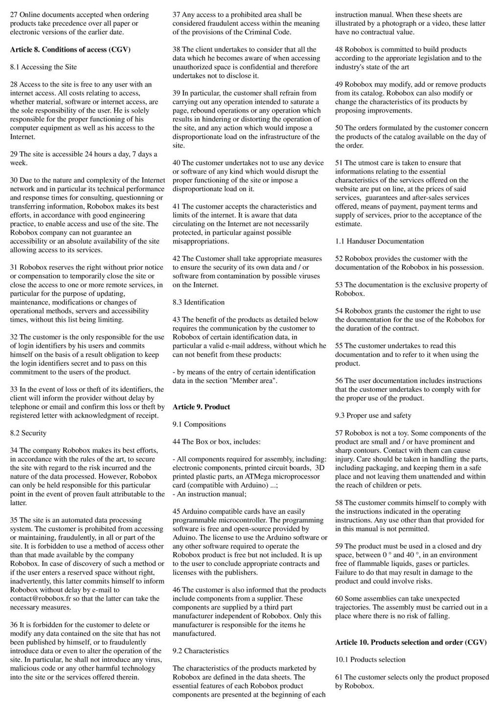
3 MOTORCYCLE _1_ CAPACITOR The first role of the capacitor is to act as a small battery, it allows you to store a charge relative to the current that is applied on it. The capacitor acts like a reservoir of water that is filled from below, the more the reservoir is filled, the more difficult it is to fill it with current. However, unlike the water tank, once the capacitor is full, no current can pass through it. In a series DC circuit, a capacitor will thus charge until it is filled and, when filled, will prevent any current from flowing and therefore will force the LED to go out. In an alternating current circuit, the capacitor can act as a filter by blocking certain frequencies. + C1 LED LED Light Capacitor charge - R1 To be effective as a small current source, our capacitor will be installed in parallel on our circuit. In this case, once the other voltage source is disconnected, the capacitor will discharge for a period oftime and turn the LED on in the meantime. + C1 - R1 LED The possible charge of the capacitor, its "capacitance" is measured in Farads (usually in microfarads). When capacitors are connected in series or parallel, the total capacitance is changed: C1 C2 C3 In Series : 1 Ctotale = 1 σ 1 Cn Ici : 1 Ctotale = 1 1 C1 + 1 C2 + 1 C3 C1 C2 C3 In Parralel : Ctotale = Cn Ici : Ctotale = C1 + C2 + C3
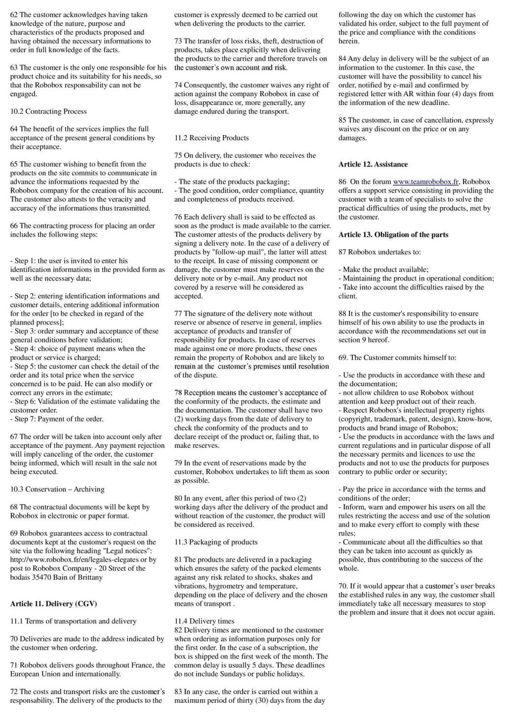
4 MOTORCYCLE _2_ TR4NSIST0R The transistor is another basic component of most electronic assemblies. It acts like a gate enabling or disabling current in a circuit. When we plug an LED on a battery, the current passes directly through the LED, we can not control it. The transistor will enable us to turn on and off the current flow, and adapt the circuit to our needs. At the core of the transistor is a "semiconductor" material, that is to say a material which transmits the current only when it is itself connected to a current source. Today we use Silicon. pin3 1KΩ b The higher the voltage at pin3, the higher the current that passes through the circuit (and the LED). 5V c e NPN Transistor GND Why not simply use the pin3 to modulate the current that is sent through the LED and do without the transistor? Well, because the current generated by the source 5V is much stronger than that generated by the pin3. The pin3 can have a voltage of 0 to 5V but can not have a current as powerful as the 5V pin. The transistor thus acts as a current amplifier. The ratio between the current in our circuit and the current from the pin3 is called the current gain. There are two types of transistors: NPN and PNP, we will focus here on NPN. A transistor therefore has three ends: The base b The transmitter The Collector c Be careful, the transistor is polarized, meaning its meaning is important. For the NPN transistor, the transmitter (e) is connected to earth. Connecting it in the opposite direction could burn the transistor.


5 Step 3 Step 2 Step 1 MOTORCYCLE _3_ BUILD Start by inserting the motor in the Motor Block", and then add the wheels on their axes. Take a cross-shaped servo horn and insert it into the fork. Note that the two sides of the horn are not exactly the same length. "S" or "Short" indicates the short side, and "L" or "Long" indicates the long side. Then slide the wheel into the fork and fix it. Slide the "Servo" into the "Block" provided for this purpose.


6 Step 5 Step 4 MOTORCYCLE _3_ BUILD You can now fit all your parts on the "Frame". The Battery Block" is located under the "Frame", the "Breadboard" on the "Boardholder", above, and the "UNO Card" on its "Cardholder" on the highest clip. Finally, you only have to hang the "Servo Block" at the front of the "Frame". Then the Motor Block" at the back of the motorcycle and the "Fork" at the front of the vehicle. For more stability, you will need to screw the horn to the servo.
7 MOTORCYCLE _4_ DC MOTOR Now let us apply our new knowledge to our circuit. In previous robots we used the L293D chip directly to operate the car, but we didn t go through much detail. Now we will use the bike to understand more precisely how a motor works. A DC motor can be inserted easily into a circuit. Just connect one side to a current source and the other one to the ground. 5V M GND This simple circuit will work but shows some limits : - The motor can only go in one direction - It can not be controlled remotely - One can not control its speed - Finally, it may send an erratic signal (noise) to the card and degrade it. pin10 One solution is to use an NPN transistor. As we saw earlier, this component allows you to remotely control whether or not the current flows in our motor. By integrating it into our circuit, we can now turn the motor on and off with pin 10. 5V M c 1KΩ b e GND We also add a diode to the assembly. The diode is an LED that emits no light but forces the current to flow only in one direction. This is important because when the engine stops, its momentum can turn it into a generator! We must therefore protect our circuits from this current.


8 MOTORCYCLE _4_ DC MOTOR Now let s plug in our Arduino, you just have to take the transistor, a motor from month 4 and your Uno card. The flat face of the transistor must face us. Motor -> Collector Motor -> 5V Emitter - > GND Base -> pin10 Let's test our circuit with this code. Here we define our motor pin at pin 10 and we set the motor speed to 0. We then set the motor pin to output and initialize communication with the serial monitor. When we type a value in the monitor we do not type it in the same language that is understood by the computer. We need to translate it from a "symbol" alphabet into an "ASCII" alphabet as shown in the table below. If the typed number is greater than 0, e transform this input into a signal worth '1 and send it through pin10. The engine will then start. We then wait 2 seconds and turn off the engine. int moteur1 = 10; int vitmoteur = 0; void setup() { pinmode(moteur1,output); Serial.begin(9600); } void loop() { vitmoteur = Serial.read()-48; if (vitmoteur >0){ Serial.print(vitMoteur); int valeur=1; digitalwrite(moteur1,valeur); delay(2000); } digitalwrite(moteur1,low); } ASCII Symbol NUL SOH / : ; < = >?


9 MOTORCYCLE _5_ REMOTE CONTROL Now we can use the remote to control our engine and turn our motorcycle into a remote controlled vehicle. The circuit is quite simple, we use the unused part of the breadboard to recreate the circuit from month 5 with an infrared sensor ready to read the instructions of the remote control. To map the behavior of our robot to the keys of our remote control, we will use the library <IRRemote.h> as explained in part II of the construction guide of month 5. You will notice that our program does not always recognize the same signal coming from our remote control. Indeed, the infrared protocol of our remote control, or the order of the HIGH-LOW sequences emitted by the IR LED at 38KHZ is not always recognized by the library. If you want to retrieve much more accurate data, you can follow our tutorial on receiving custom IR signals on teamrobobox. In addition to receiving the instruction "engine on" or "engine off", our program must be able to rotate the front wheel of the motorcycle. We will use the "right" and "left" keys on the remote control to allow the motorcycle to rotate: Pressing "left" once will rotate the wheel 15 to the left Pressing "right" once will rotate the wheel 15 to the right. Pressing these buttons repeatedly increases the front wheel angle accordingly.


10 MOTORCYCLE _5_ REMOTE CONTROL We went through the different steps to build this robot: using the motor, the role of the transistor and the use of the infrared receiver. Let us now see how the whole circuit is organized. First we add two libraries : IRremote.h and Servo.h. We will use them to manage the remote control and the servomotor. Then we define several variables, motor1 will be the pin from which we will send our instruction to the engine. This pin will therefore be connected to the 'base' of the transistor. Then we will set the motor speed to 0 and we will define pin 5 as that of the infrared sensor. As in box5 we will create the two IRrecv and decode_results objects to hold the IR sensor data. In the setup() we will define motor1 s pin as an output, start the receiver and attach the servomotor to pin 3. In the loop() we will use the same code as in month 5 for the IR sensor data, but we will additionally run the action() function. #include <IRremote.h> #include <Servo.h> int moteur1 = 10; int vitmoteur =0; int IRpin = 5; long val; int servoangle; IRrecv irrecv(irpin); decode_results results; Servo servo1; void setup() { pinmode(moteur1,output); irrecv.enableirin(); servo1.attach(3); } void loop() { if (irrecv.decode(&results)) { val = results.value; action(val); irrecv.resume(); }; }

11 MOTORCYCLE _5_ REMOTE CONTROL The action() function takes as parameter the value received from this IR remote. This will be used to customize the behavior of our robot. The values received by the sensor depend on the buttons being pushed. You can go back to box 5 to see how to adapt these values to the values emitted by your remote control. The action() function will then direct our program to another function, depending on the value received: turnright() will rotate the front wheel to the right turnleft() will rotate the front wheel to the left Accelere() will start the engine. stop() simply stops the car. Your motorcycle should now be controllable with your remote control! If it goes too fast, do not hesitate to connect the transistor to the 3.3V pin instead of the 5V. void action(long token){ if(token == ){ tournedroite();} else if(token == ){ tournegauche();} else if(token == ){ accelere(); } else if(token == ){ arret(); } } void tournedroite(){ servoangle = min(180,servoangle +15); servo1.write(servoangle); } void tournegauche(){ servoangle = max(0,servoangle -15); servo1.write(servoangle); } void accelere(){ analogwrite(moteur1,1); } void arret(){ analogwrite(moteur1,0); } The motorcycle now turns left and right, but the 15 steps are not really "soft". The challenge of this month is therefore to create a function that increases the angle of the front wheel as long as a key (right to the left) is maintained. Good luck to you!
12 MAIN FUNCTIONS USED IN ARDUINO Here is a list of the most used functions in Arduino programs pinmode (Pin, Mode): Pin = Pin number on the card Mode = OUTPUT or INPUT Defines whether Pin data is sent (Output) or received (Input) into the card. digitalread (Pin): Pin = Port read by the function. Read the port 'Pin' to see its value (LOW for 0V or HIGH for 5V) digitalwrite (Pin, Value): Pin = Pin used Value = LOW or HIGH Sends a value via the 'Pin' port, either LOW for 0V or HIGH for 5V random (Start, End): Start & End = real numbers The random function gives a real number between the number 'Start' and the number End'-1. Delay(value): Value is an integer representing milliseconds. This will pause program execution for some time, given in milliseconds millis(): Displays the number of milliseconds since the program was launched Serial.begin(Baud) Baud = Integer. Serial.begin(Baud) initiates communication with the Arduino program interface. The Baud number corresponds to the 'BaudRate', that is to say the number of bits per second sent through the USB cable between our Arduino board and the computer. Establishing a communication between the Arduino and the computer allows you to monitor the execution of the program, to try to debug it, but also to send instructions from the computer to the card. Serial.println(Value): Value = Any variable This function is used to write the variable 'Value' in the Arduino interface. This command is especially useful for debugging our programs!
13 MAIN FUNCTIONS USED IN ARDUINO After writing your code, and sending it to your card, you will surely see some error messages. Here is a non-exhaustive list of common errors on Arduino: The card is not found When your card is not recognized by the program, you will see the message below: stk500_recv(): programmer is not responding avrdude: stk500_getsync() attempt n of 10: not in sync: resp=0x00 We solve this error by clicking 'tools' in the menu bar of Arduino and then checking that the correct model of 'board' is selected, as well as the right 'port'. A ; was forgotten This is probably the most common mistake! One of the features of C (or C ++) is to require a semicolon ; At the end ofeach expression. Otherwise, you will get something like this : sketch_mar28a.ino: In function 'void loop()': sketch_mar28a:9: error: expected ',' or ';' before '}' token expected ',' or ';' before '}' token The syntax was inccorect Another characteristic of C / C ++ is to be 'case-sensitive' ie to understand a letter with a capital letter as different from a letter without capital letter. For example : digitalwrite( ledpin, HIGH); // will work DigitalWrite( ledpin, HIGH); // will not work You will get an error like this: «DigitalWrite' was not declared in this scope» Because C / C ++ thinks this is a function!
14
15
16
CONSTRUCTION GUIDE Robotic Arm. Robobox. Level II
 CONSTRUCTION GUIDE Robotic Arm Robobox Level II Robotic Arm This month s robot is a robotic arm with two degrees of freedom that will teach you how to use motors. You will then be able to move the arm
CONSTRUCTION GUIDE Light Robot. Robobox. Level VI
 CONSTRUCTION GUIDE Light Robot Robobox Level VI The Light In this box dedicated to light we will discover, through 3 projects, how light can be used in our robots. First we will see how to insert headlights
Experiment 1 Identification of Components and Breadboard Realization
 Experiment 1 Identification of Components and Breadboard Realization Aim: Introduction to the lab and identification of various components and realization using bread board. Hardware/Software Required:
Objectives: Learn what an Arduino is and what it can do Learn what an LED is and how to use it Be able to wire and program an LED to blink
 Objectives: Learn what an Arduino is and what it can do Learn what an LED is and how to use it Be able to wire and program an LED to blink By the end of this session: You will know how to use an Arduino
Coding with Arduino to operate the prosthetic arm
 Setup Board Install FTDI Drivers This is so that your RedBoard will be able to communicate with your computer. If you have Windows 8 or above you might already have the drivers. 1. Download the FTDI driver
Attribution Thank you to Arduino and SparkFun for open source access to reference materials.
 Attribution Thank you to Arduino and SparkFun for open source access to reference materials. Contents Parts Reference... 1 Installing Arduino... 7 Unit 1: LEDs, Resistors, & Buttons... 7 1.1 Blink (Hello
EE-110 Introduction to Engineering & Laboratory Experience Saeid Rahimi, Ph.D. Labs Introduction to Arduino
 EE-110 Introduction to Engineering & Laboratory Experience Saeid Rahimi, Ph.D. Labs 10-11 Introduction to Arduino In this lab we will introduce the idea of using a microcontroller as a tool for controlling
The Motor sketch. One Direction ON-OFF DC Motor
 One Direction ON-OFF DC Motor The DC motor in your Arduino kit is the most basic of electric motors and is used in all types of hobby electronics. When current is passed through, it spins continuously
Programming 2 Servos. Learn to connect and write code to control two servos.
 Programming 2 Servos Learn to connect and write code to control two servos. Many students who visit the lab and learn how to use a Servo want to use 2 Servos in their project rather than just 1. This lesson
FABO ACADEMY X ELECTRONIC DESIGN
 ELECTRONIC DESIGN MAKE A DEVICE WITH INPUT & OUTPUT The Shanghaino can be programmed to use many input and output devices (a motor, a light sensor, etc) uploading an instruction code (a program) to it
For this exercise, you will need a partner, an Arduino kit (in the plastic tub), and a laptop with the Arduino programming environment.
, and a laptop with the Arduino programming environment.") Physics 222 Name: Exercise 6: Mr. Blinky This exercise is designed to help you wire a simple circuit based on the Arduino microprocessor, which is a particular brand of microprocessor that also includes
Physics 222 Name: Exercise 6: Mr. Blinky This exercise is designed to help you wire a simple circuit based on the Arduino microprocessor, which is a particular brand of microprocessor that also includes
Application Note. Communication between arduino and IMU Software capturing the data
 Application Note Communication between arduino and IMU Software capturing the data ECE 480 Team 8 Chenli Yuan Presentation Prep Date: April 8, 2013 Executive Summary In summary, this application note is
A servo is an electric motor that takes in a pulse width modulated signal that controls direction and speed. A servo has three leads:
 Project 4: Arduino Servos Part 1 Description: A servo is an electric motor that takes in a pulse width modulated signal that controls direction and speed. A servo has three leads: a. Red: Current b. Black:
Module: Arduino as Signal Generator
 Name/NetID: Teammate/NetID: Module: Laboratory Outline In our continuing quest to access the development and debugging capabilities of the equipment on your bench at home Arduino/RedBoard as signal generator.
J. La Favre Using Arduino with Raspberry Pi February 7, 2018
 As you have already discovered, the Raspberry Pi is a very capable digital device. Nevertheless, it does have some weaknesses. For example, it does not produce a clean pulse width modulation output (unless
Electronic Components
 Electronic Components Arduino Uno Arduino Uno is a microcontroller (a simple computer), it has no way to interact. Building circuits and interface is necessary. Battery Snap Battery Snap is used to connect
1. Introduction to Analog I/O
 EduCake Analog I/O Intro 1. Introduction to Analog I/O In previous chapter, we introduced the 86Duino EduCake, talked about EduCake s I/O features and specification, the development IDE and multiple examples
CONSTRUCTION GUIDE IR Alarm. Robobox. Level I
 CONSTRUCTION GUIDE Robobox Level I This month s montage is an that will allow you to detect any intruder. When a movement is detected, the alarm will turn its LEDs on and buzz to a personalized tune. 1X
HAW-Arduino. Sensors and Arduino F. Schubert HAW - Arduino 1
 HAW-Arduino Sensors and Arduino 14.10.2010 F. Schubert HAW - Arduino 1 Content of the USB-Stick PDF-File of this script Arduino-software Source-codes Helpful links 14.10.2010 HAW - Arduino 2 Report for
Lab 2: Blinkie Lab. Objectives. Materials. Theory
 Lab 2: Blinkie Lab Objectives This lab introduces the Arduino Uno as students will need to use the Arduino to control their final robot. Students will build a basic circuit on their prototyping board and
Computational Crafting with Arduino. Christopher Michaud Marist School ECEP Programs, Georgia Tech
 Computational Crafting with Arduino Christopher Michaud Marist School ECEP Programs, Georgia Tech Introduction What do you want to learn and do today? Goals with Arduino / Computational Crafting Purpose
Blink. EE 285 Arduino 1
 Blink At the end of the previous lecture slides, we loaded and ran the blink program. When the program is running, the built-in LED blinks on and off on for one second and off for one second. It is very
Assignments from last week
 Assignments from last week Review LED flasher kits Review protoshields Need more soldering practice (see below)? http://www.allelectronics.com/make-a-store/category/305/kits/1.html http://www.mpja.com/departments.asp?dept=61
Disclaimer. Arduino Hands-On 2 CS5968 / ART4455 9/1/10. ! Many of these slides are mine. ! But, some are stolen from various places on the web
 Arduino Hands-On 2 CS5968 / ART4455 Disclaimer! Many of these slides are mine! But, some are stolen from various places on the web! todbot.com Bionic Arduino and Spooky Arduino class notes from Tod E.Kurt!
Welcome to Arduino Day 2016
 Welcome to Arduino Day 2016 An Intro to Arduino From Zero to Hero in an Hour! Paul Court (aka @Courty) Welcome to the SLMS Arduino Day 2016 Arduino / Genuino?! What?? Part 1 Intro Quick Look at the Uno
Lesson 13. The Big Idea: Lesson 13: Infrared Transmitters
 Lesson Lesson : Infrared Transmitters The Big Idea: In Lesson 12 the ability to detect infrared radiation modulated at 38,000 Hertz was added to the Arduino. This lesson brings the ability to generate
Using Transistors and Driving Motors
 Chapter 4 Using Transistors and Driving Motors Parts You ll Need for This Chapter: Arduino Uno USB cable 9V battery 9V battery clip 5V L4940V5 linear regulator 22uF electrolytic capacitor.1uf electrolytic
MAE106 Laboratory Exercises Lab # 1 - Laboratory tools
 MAE106 Laboratory Exercises Lab # 1 - Laboratory tools University of California, Irvine Department of Mechanical and Aerospace Engineering Goals To learn how to use the oscilloscope, function generator,
CURIE Academy, Summer 2014 Lab 2: Computer Engineering Software Perspective Sign-Off Sheet
 Lab : Computer Engineering Software Perspective Sign-Off Sheet NAME: NAME: DATE: Sign-Off Milestone TA Initials Part 1.A Part 1.B Part.A Part.B Part.C Part 3.A Part 3.B Part 3.C Test Simple Addition Program
Figure 1. Digilent DC Motor
 Laboratory 9 - Usage of DC- and servo-motors The current laboratory describes the usage of DC and servomotors 1. DC motors Figure 1. Digilent DC Motor Classical DC motors are converting electrical energy
Lesson 3: Arduino. Goals
 Introduction: This project introduces you to the wonderful world of Arduino and how to program physical devices. In this lesson you will learn how to write code and make an LED flash. Goals 1 - Get to
Lecture 4: Basic Electronics. Lecture 4 Brief Introduction to Electronics and the Arduino
 Lecture 4: Basic Electronics Lecture 4 Page: 1 Brief Introduction to Electronics and the Arduino colintan@nus.edu.sg Lecture 4: Basic Electronics Page: 2 Objectives of this Lecture By the end of today
PLAN DE FORMACIÓN EN LENGUAS EXTRANJERAS IN-57 Technology for ESO: Contents and Strategies
 Lesson Plan: Traffic light with Arduino using code, S4A and Ardublock Course 3rd ESO Technology, Programming and Robotic David Lobo Martínez David Lobo Martínez 1 1. TOPIC Arduino is an open source hardware
Rodni What will yours be?
 Rodni What will yours be? version 4 Welcome to Rodni, a modular animatronic animal of your own creation for learning how easy it is to enter the world of software programming and micro controllers. During
Arduino An Introduction
 Arduino An Introduction Hardware and Programming Presented by Madu Suthanan, P. Eng., FEC. Volunteer, Former Chair (2013-14) PEO Scarborough Chapter 2 Arduino for Mechatronics 2017 This note is for those
MICROCONTROLLERS BASIC INPUTS and OUTPUTS (I/O)
") PH-315 Portland State University MICROCONTROLLERS BASIC INPUTS and OUTPUTS (I/O) ABSTRACT A microcontroller is an integrated circuit containing a processor and programmable read-only memory, 1 which is
PH-315 Portland State University MICROCONTROLLERS BASIC INPUTS and OUTPUTS (I/O) ABSTRACT A microcontroller is an integrated circuit containing a processor and programmable read-only memory, 1 which is
Experiment 1: Robot Moves in 3ft squared makes sound and
 Experiment 1: Robot Moves in 3ft squared makes sound and turns on an LED at each turn then stop where it started. Edited: 9-7-2015 Purpose: Press a button, make a sound and wait 3 seconds before starting
Sten-Bot Robot Kit Stensat Group LLC, Copyright 2013
 Sten-Bot Robot Kit Stensat Group LLC, Copyright 2013 Legal Stuff Stensat Group LLC assumes no responsibility and/or liability for the use of the kit and documentation. There is a 90 day warranty for the
TV Remote. Discover Engineering. Youth Handouts
 Discover Engineering Youth Handouts Electronic Component Guide Component Symbol Notes Amplifier chip 1 8 2 7 3 6 4 5 Capacitor LED The amplifier chip (labeled LM 386) has 8 legs, or pins. Each pin connects
Mechatronics Engineering and Automation Faculty of Engineering, Ain Shams University MCT-151, Spring 2015 Lab-4: Electric Actuators
 Mechatronics Engineering and Automation Faculty of Engineering, Ain Shams University MCT-151, Spring 2015 Lab-4: Electric Actuators Ahmed Okasha, Assistant Lecturer okasha1st@gmail.com Objective Have a
TWEAK THE ARDUINO LOGO
 TWEAK THE ARDUINO LOGO Using serial communication, you'll use your Arduino to control a program on your computer Discover : serial communication with a computer program, Processing Time : 45 minutes Level
Project 27 Joystick Servo Control
 Project 27 Joystick Servo Control For another simple project, let s use a joystick to control the two servos. You ll arrange the servos in such a way that you get a pan-tilt head, such as is used for CCTV
Lab 06: Ohm s Law and Servo Motor Control
 CS281: Computer Systems Lab 06: Ohm s Law and Servo Motor Control The main purpose of this lab is to build a servo motor control circuit. As with prior labs, there will be some exploratory sections designed
Motors and Servos Part 2: DC Motors
 Motors and Servos Part 2: DC Motors Back to Motors After a brief excursion into serial communication last week, we are returning to DC motors this week. As you recall, we have already worked with servos
Arduino Application: Speed control of small DC Motors
 Arduino Application: Speed control of small DC Motors ME 120 Mechanical and Materials Engineering Portland State University http://web.cecs.pdx.edu/~me120 Learning Objectives Be able to describe the use
The Robot Builder's Shield for Arduino
 The Robot Builder's Shield for Arduino by Ro-Bot-X Designs Introduction. The Robot Builder's Shield for Arduino was especially designed to make building robots with Arduino easy. The built in dual motors
Servomotor Control with Arduino Integrated Development Environment. Application Notes. Bingyang Wu Mar 27, Introduction
 Servomotor Control with Arduino Integrated Development Environment Application Notes Bingyang Wu Mar 27, 2015 Introduction Arduino is a tool for making computers that can sense and control more of the
Boe-Bot robot manual
 Tallinn University of Technology Department of Computer Engineering Chair of Digital Systems Design Boe-Bot robot manual Priit Ruberg Erko Peterson Keijo Lass Tallinn 2016 Contents 1 Robot hardware description...3
// Parts of a Multimeter
 Using a Multimeter // Parts of a Multimeter Often you will have to use a multimeter for troubleshooting a circuit, testing components, materials or the occasional worksheet. This section will cover how
Portland State University MICROCONTROLLERS
 PH-315 MICROCONTROLLERS INTERRUPTS and ACCURATE TIMING I Portland State University OBJECTIVE We aim at becoming familiar with the concept of interrupt, and, through a specific example, learn how to implement
Programming a Servo. Servo. Red Wire. Black Wire. White Wire
 Programming a Servo Learn to connect wires and write code to program a Servo motor. If you have gone through the LED Circuit and LED Blink exercises, you are ready to move on to programming a Servo. A
C++ PROGRAM FOR DRIVING OF AN AGRICOL ROBOT
 Annals of the University of Petroşani, Mechanical Engineering, 14 (2012), 11-19 11 C++ PROGRAM FOR DRIVING OF AN AGRICOL ROBOT STELIAN-VALENTIN CASAVELA 1 Abstract: This robot is projected to participate
Megamark Arduino Library Documentation
 Megamark Arduino Library Documentation The Choitek Megamark is an advanced full-size multipurpose mobile manipulator robotics platform for students, artists, educators and researchers alike. In our mission
1. Controlling the DC Motors
 E11: Autonomous Vehicles Lab 5: Motors and Sensors By this point, you should have an assembled robot and Mudduino to power it. Let s get things moving! In this lab, you will write code to test your motors
Tarocco Closed Loop Motor Controller
 Contents Safety Information... 3 Overview... 4 Features... 4 SoC for Closed Loop Control... 4 Gate Driver... 5 MOSFETs in H Bridge Configuration... 5 Device Characteristics... 6 Installation... 7 Motor
Parts List. Robotic Arm segments ¼ inch screws Cable XBEE module or Wifi module
 Robotic Arm 1 Legal Stuff Stensat Group LLC assumes no responsibility and/or liability for the use of the kit and documentation. There is a 90 day warranty for the Sten-Bot kit against component defects.
Two Hour Robot. Lets build a Robot.
 Lets build a Robot. Our robot will use an ultrasonic sensor and servos to navigate it s way around a maze. We will be making 2 voltage circuits : A 5 Volt for our ultrasonic sensor, sound and lights powered
DFRduino Romeo All in one Controller V1.1(SKU:DFR0004)
") DFRduino Romeo All in one Controller V1.1(SKU:DFR0004) DFRduino RoMeo V1.1 Contents 1 Introduction 2 Specification 3 DFRduino RoMeo Pinout 4 Before you start 4.1 Applying Power 4.2 Software 5 Romeo Configuration
DFRduino Romeo All in one Controller V1.1(SKU:DFR0004) DFRduino RoMeo V1.1 Contents 1 Introduction 2 Specification 3 DFRduino RoMeo Pinout 4 Before you start 4.1 Applying Power 4.2 Software 5 Romeo Configuration
Experiment #3: Micro-controlled Movement
 Experiment #3: Micro-controlled Movement So we re already on Experiment #3 and all we ve done is blinked a few LED s on and off. Hang in there, something is about to move! As you know, an LED is an output
Arduino Lesson 1. Blink. Created by Simon Monk
 Arduino Lesson 1. Blink Created by Simon Monk Guide Contents Guide Contents Overview Parts Part Qty The 'L' LED Loading the 'Blink' Example Saving a Copy of 'Blink' Uploading Blink to the Board How 'Blink'
Pulse Width Modulation and
 Pulse Width Modulation and analogwrite ( ); 28 Materials needed to wire one LED. Odyssey Board 1 dowel Socket block Wire clip (optional) 1 Female to Female (F/F) wire 1 F/F resistor wire LED Note: The
INA169 Breakout Board Hookup Guide
 Page 1 of 10 INA169 Breakout Board Hookup Guide CONTRIBUTORS: SHAWNHYMEL Introduction Have a project where you want to measure the current draw? Need to carefully monitor low current through an LED? The
Introduction to Arduino HW Labs
 Introduction to Arduino HW Labs In the next six lab sessions, you ll attach sensors and actuators to your Arduino processor This session provides an overview for the devices LED indicators Text/Sound Output
Studuino Icon Programming Environment Guide
 Studuino Icon Programming Environment Guide Ver 0.9.6 4/17/2014 This manual introduces the Studuino Software environment. As the Studuino programming environment develops, these instructions may be edited
BeeLine TX User s Guide V1.1c 4/25/2005
 BeeLine TX User s Guide V1.1c 4/25/2005 1 Important Battery Information The BeeLine Transmitter is designed to operate off of a single cell lithium polymer battery. Other battery sources may be used, but
Blue Point Engineering
 Blue Point Engineering Instruction I www.bpesolutions.com Pointing the Way to Solutions! Animatronic Wizard - 3 Board (BPE No. WAC-0030) Version 3.0 2009 Controller Page 1 The Wizard 3 Board will record
SPI, Talking to Chips, and Minimizing Noise
 Jonathan Mitchell 996069032 Stark Industries Application Note SPI, Talking to Chips, and Minimizing Noise How do you communicate with a piece of silicon? How do you communicate with a semiconductor. SPI
MICROCONTROLLERS BASIC INPUTS and OUTPUTS (I/O)
") PH-315 Portland State University MICROCONTROLLERS BASIC INPUTS and OUTPUTS (I/O) ABSTRACT A microcontroller is an integrated circuit containing a processor and programmable read-only memory, 1 which is
PH-315 Portland State University MICROCONTROLLERS BASIC INPUTS and OUTPUTS (I/O) ABSTRACT A microcontroller is an integrated circuit containing a processor and programmable read-only memory, 1 which is
Setup Download the Arduino library (link) for Processing and the Lab 12 sketches (link).
 for Processing and the Lab 12 sketches (link).") Lab 12 Connecting Processing and Arduino Overview In the previous lab we have examined how to connect various sensors to the Arduino using Scratch. While Scratch enables us to make simple Arduino programs,
Lab 12 Connecting Processing and Arduino Overview In the previous lab we have examined how to connect various sensors to the Arduino using Scratch. While Scratch enables us to make simple Arduino programs,
Arduino Control of Tetrix Prizm Robotics. Motors and Servos Introduction to Robotics and Engineering Marist School
 Arduino Control of Tetrix Prizm Robotics Motors and Servos Introduction to Robotics and Engineering Marist School Motor or Servo? Motor Faster revolution but less Power Tetrix 12 Volt DC motors have a
LAB 1 AN EXAMPLE MECHATRONIC SYSTEM: THE FURBY
 LAB 1 AN EXAMPLE MECHATRONIC SYSTEM: THE FURBY Objectives Preparation Tools To see the inner workings of a commercial mechatronic system and to construct a simple manual motor speed controller and current
2D Floor-Mapping Car
 CDA 4630 Embedded Systems Final Report Group 4: Camilo Moreno, Ahmed Awada ------------------------------------------------------------------------------------------------------------------------------------------
Introduction. 1 of 44
 Introduction I set out to create this robot kit to give teachers, students, and hobbyists an affordable way to start learning and sharing robotics in their community. Most robotics kits that have the same
Electronics, Sensors, and Actuators
 Electronics, Sensors, and Actuators 4/14/15 David Flicker BE107 Overview Basic electronics and components Sensors Actuators Electronics 101 Voltage, V, is fundamentally how much energy is gained or lost
Lecture 6. Interfacing Digital and Analog Devices to Arduino. Intro to Arduino
 Lecture 6 Interfacing Digital and Analog Devices to Arduino. Intro to Arduino PWR IN USB (to Computer) RESET SCL\SDA (I2C Bus) POWER 5V / 3.3V / GND Analog INPUTS Digital I\O PWM(3, 5, 6, 9, 10, 11) Components
Experiment 15: Diode Lab Part 1
 Experiment 15: Diode Lab Part 1 Purpose Theory Overview EQUIPMENT NEEDED: Computer and Science Workshop Interface Power Amplifier (CI-6552A) (2) Voltage Sensor (CI-6503) AC/DC Electronics Lab Board (EM-8656)
INTRODUCTION to MICRO-CONTROLLERS
 PH-315 Portland State University INTRODUCTION to MICRO-CONTROLLERS Bret Comnes, Dan Lankow, and Andres La Rosa 1. ABSTRACT A microcontroller is an integrated circuit containing a processor and programmable
HANDS-ON LAB INSTRUCTION SHEET MODULE 3 CAPACITORS, TIME CONSTANTS AND TRANSISTOR GAIN
 HANDS-ON LAB INSTRUCTION SHEET MODULE 3 CAPACITORS, TIME CONSTANTS AND TRANSISTOR GAIN NOTES: 1) To conserve the life of the Multimeter s 9 volt battery, be sure to turn the meter off if not in use for
Arduino Advanced Projects
 Arduino Advanced Projects Created as a companion manual to the Toronto Public Library Arduino Kits. Arduino Advanced Projects Copyright 2017 Toronto Public Library. All rights reserved. Published by the
The µbotino Microcontroller Board
 The µbotino Microcontroller Board by Ro-Bot-X Designs Introduction. The µbotino Microcontroller Board is an Arduino compatible board for small robots. The 5x5cm (2x2 ) size and the built in 3 pin connectors
Chapter 14. using data wires
 Chapter 14. using data wires In this fifth part of the book, you ll learn how to use data wires (this chapter), Data Operations blocks (Chapter 15), and variables (Chapter 16) to create more advanced programs
Preface. If you have any problems for learning, please contact us at We will do our best to help you solve the problem.
 Preface Adeept is a technical service team of open source software and hardware. Dedicated to applying the Internet and the latest industrial technology in open source area, we strive to provide best hardware
100UF CAPACITOR POTENTIOMETER SERVO MOTOR MOTOR ARM. MALE HEADER PIN (3 pins) INGREDIENTS
 INGREDIENTS") 05 POTENTIOMETER SERVO MOTOR MOTOR ARM 100UF CAPACITOR MALE HEADER PIN (3 pins) INGREDIENTS 63 MOOD CUE USE A SERVO MOTOR TO MAKE A MECHANICAL GAUGE TO POINT OUT WHAT SORT OF MOOD YOU RE IN THAT DAY Discover:
05 POTENTIOMETER SERVO MOTOR MOTOR ARM 100UF CAPACITOR MALE HEADER PIN (3 pins) INGREDIENTS 63 MOOD CUE USE A SERVO MOTOR TO MAKE A MECHANICAL GAUGE TO POINT OUT WHAT SORT OF MOOD YOU RE IN THAT DAY Discover:
Experiment 4.B. Position Control. ECEN 2270 Electronics Design Laboratory 1
 Experiment 4.B Position Control Electronics Design Laboratory 1 Procedures 4.B.1 4.B.2 4.B.3 4.B.4 Read Encoder with Arduino Position Control by Counting Encoder Pulses Demo Setup Extra Credit Electronics
Activity 2: Opto Receiver
 Activity 2: Opto Receiver Time Required: 45 minutes Materials List Group Size: 2 Each pair needs: One each of: One Activity 2 bag containing: o Two 10 μf Electrolytic Capacitors o 47 μf Electrolytic Capacitor
Micro Wizard Instructions
 How to install FAST TRACK K3 4-digit actual times and 1-digit sequence of finish display timer with Computer Serial Interface Enclosed you will find the Fast Track finish line, AC adapter and remote start
Capacitive Touch with Conductive Fabric & Flora
 Capacitive Touch with Conductive Fabric & Flora Created by Becky Stern Last updated on 2015-02-20 01:17:52 PM EST Guide Contents Guide Contents Overview Tools & supplies Wiring the circuit Code Adding
Lesson4 Obstacle avoidance car
 Lesson4 Obstacle avoidance car 1 Points of this section The joy of learning, is not just know how to control your car, but also know how to protect your car. So, make you car far away from collision. Learning
SCHOOL OF TECHNOLOGY AND PUBLIC MANAGEMENT ENGINEERING TECHNOLOGY DEPARTMENT
 SCHOOL OF TECHNOLOGY AND PUBLIC MANAGEMENT ENGINEERING TECHNOLOGY DEPARTMENT Course ENGT 3260 Microcontrollers Summer III 2015 Instructor: Dr. Maged Mikhail Project Report Submitted By: Nicole Kirch 7/10/2015
Embedded Controls Final Project. Tom Hall EE /07/2011
 Embedded Controls Final Project Tom Hall EE 554 12/07/2011 Introduction: The given task was to design a system that: -Uses at least one actuator and one sensor -Determine a controlled variable and suitable
ECE 511: FINAL PROJECT REPORT GROUP 7 MSP430 TANK
 ECE 511: FINAL PROJECT REPORT GROUP 7 MSP430 TANK Team Members: Andrew Blanford Matthew Drummond Krishnaveni Das Dheeraj Reddy 1 Abstract: The goal of the project was to build an interactive and mobile
Experiment Manual Electronics Learning Circuits Manual Cover.indd 1 3/29/11 2:19 PM
 Experiment Manual Instruction Manual Contents 4 Introduction 2 Electronics 3 The parts in your kit 6 Tips for assembling the circuits 9 Getting started with light-emitting diodes 0 Red light with green
T6+ Analog I/O Section. Installation booklet for part numbers: 5/4-80A-115 5/4-90A-115 5/4-80A /4-90A-1224
 T and T+ are trade names of Trol Systems Inc. TSI reserves the right to make changes to the information contained in this manual without notice. publication /4A115MAN- rev:1 2001 TSI All rights reserved
Lesson 2 Bluetooth Car
 Lesson 2 Bluetooth Car Points of this section It is very important and so cool to control your car wirelessly in a certain space when we learn the Arduino, so in the lesson, we will teach you how to control
The Transistor Tester user manual
 The Transistor Tester user manual Power: The Transistor Tester can be powered from 6.8V-12V DC. This can be achieved by a 9V layerbuilt battery or two 3.7V Lithium-ion battery in series, or with a 9V DC
Robotics using Lego Mindstorms EV3 (Intermediate)
") Robotics using Lego Mindstorms EV3 (Intermediate) Facebook.com/roboticsgateway @roboticsgateway Robotics using EV3 Are we ready to go Roboticists? Does each group have at least one laptop? Do you have
Robotics using Lego Mindstorms EV3 (Intermediate) Facebook.com/roboticsgateway @roboticsgateway Robotics using EV3 Are we ready to go Roboticists? Does each group have at least one laptop? Do you have
Understanding the Arduino to LabVIEW Interface
 E-122 Design II Understanding the Arduino to LabVIEW Interface Overview The Arduino microcontroller introduced in Design I will be used as a LabVIEW data acquisition (DAQ) device/controller for Experiments
Microcontrollers and Interfacing
 Microcontrollers and Interfacing Week 07 digital input, debouncing, interrupts and concurrency College of Information Science and Engineering Ritsumeikan University 1 this week digital input push-button
ADVANCED SAFETY APPLICATIONS FOR RAILWAY CROSSING
 ADVANCED SAFETY APPLICATIONS FOR RAILWAY CROSSING 1 HARSHUL BALANI, 2 CHARU GUPTA, 3 KRATIKA SUKHWAL 1,2,3 B.TECH (ECE), Poornima College Of Engineering, RTU E-mail; 1 harshul.balani@gmail.com, 2 charu95g@gmail.com,
5v AC R. 12v. 1kohm. F=35KHz oscilloscope. 3 Final Project OFF. ON Toggle Switch. Relay 5v 2N3906 2N uF LM311. IR Detector +5v GND LED PNP NPN
 3 Final Project Diode 103 IR Detector OFF ON Toggle Switch IR Detector +5v Push Button IR 100uF LED + GND LDR C Preset R 7805 IN GND OUT Relay 5v + PNP 2N3906 1 Kohm NPN 2N3904 4 3 2 1 555 5 6 7 8 4 3