HAW-Arduino. Sensors and Arduino F. Schubert HAW - Arduino 1
|
|
|
- Daniella Reed
- 5 years ago
- Views:
Transcription
1 HAW-Arduino Sensors and Arduino F. Schubert HAW - Arduino 1
2 Content of the USB-Stick PDF-File of this script Arduino-software Source-codes Helpful links HAW - Arduino 2
3 Report for the Tasks Description Datasheets Schematics Calculations Source-codes with comments Documentation of the results HAW - Arduino 3
4 First Steps Introduction Hardware and software Installation of the environment The first Arduino-program Inputs and outputs Voltmeter Thermometer Piezo sensor Servo-motor HAW - Arduino 4
5 The Hardware HAW-Arduino USB-Board Breadboard small Breadboard big USB cable Piezo-buzzer Potentiometer Switches LEDs Transistor Resistors Photoresistor Photodiode LCD-module NTC Operational amplifier Comparator Wires Cables Soldering equipment Socket strips Connectors Experimentation board Relay IR-transmitter HAW - Arduino 5

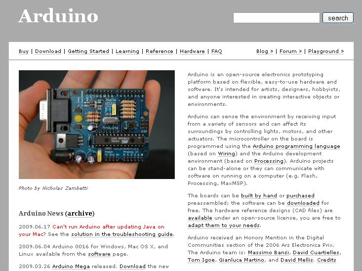

6 What means Arduino? Hardware Programming-software Community HAW - Arduino 6
7 Hardware Cheap, fast and open AVR ATmega 168 (328) Microcontroller C-Programming Programming via USB Power supply via USB or external HAW - Arduino 7
8 Arduino Characteristics 16 kbyte EEPROM 1 kbyte RAM 16 MHz Clock Inputs and Outputs 14 digital Inputs/Outputs 6 analog Inputs 6 PWM-Outputs I 2 C-Bus, serial Bus (TX/RX) HAW - Arduino 8
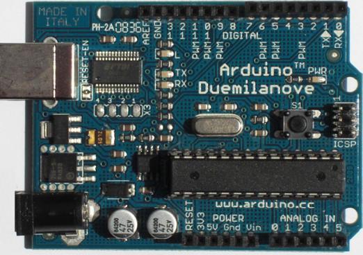
9 Arduino Duemilanove Board LED at Pin 13 Digital Inputs and Outputs USB Connector TX / RX LEDs Reset Button Power LED Microcontroller External Power Supply Analog Inputs HAW - Arduino 9
10 Arduino Duemilanove Schematic HAW - Arduino 10

11 Arduino-Software Verify (Compile) Stop New Serial Monitor ON Upload to I/O Board Open Save Status Field Status Messages HAW - Arduino 11
12 Installation Unzip of the Arduino-software Connection of the Arduino-board Installation of the drivers (administrator rights needed) Reboot the computer Run the Arduino-software Go on HAW - Arduino 12

13 Unzip the Arduino-Softwae HAW - Arduino 13

14 Connection of the Arduino-Board LED at Pin 13 blinks Power LED is on HAW - Arduino 14
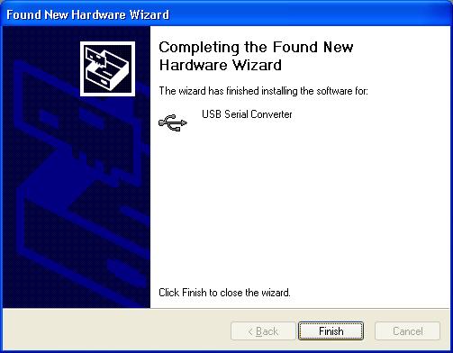
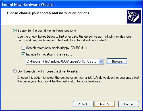
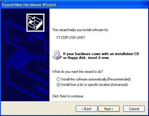
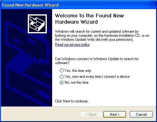
15 Driver Installation HAW - Arduino 15

16 Selecting the COM-Port HAW - Arduino 16

17 Selecting the Board HAW - Arduino 17
18 Status-Messages Upload done Wrong serial port Wrong board HAW - Arduino 18
 at the bottom to determine the problem The status area shows what is wrong 14.10.")
19 Troubleshooting Press the reset-button on Arduino and try again Check the serial port (Connection and number) Read the red text (Debugging output) at the bottom to determine the problem The status area shows what is wrong HAW - Arduino 19
20 Cycle of Development EDIT UPLOAD COMPILE UPLOAD COMPILE YES ERROR? UPLOAD YES ERROR? YES ERROR? RUN HAW - Arduino 20
21 Declaration of variables Program-Structure int ledpin = 13; // LED connected to digital pin 13 Initialization setup( ) Set the inputs and outputs void setup() { pinmode(ledpin, OUTPUT); } Main program loop( ) Loop without end // run once, when the sketch starts // sets the digital pin as output void loop() { digitalwrite(ledpin, HIGH); delay(1000); digitalwrite(ledpin, LOW); delay(1000); } // run over and over again // sets the LED on // waits for a second // sets the LED off // waits for a second HAW - Arduino 21
22 The blinking LED HAW - Arduino 22

23 Program Examples HAW - Arduino 23


24 Hardware HAW-Arduino Small Breadboard Big Breadboard HAW - Arduino 24

25 Solderless Breadboard Not connected All connected All connected Group of 5 connected HAW - Arduino HAW - Arduino 25


26 Preparing special pins Turn pin by 90!!! HAW - Arduino 26
27 Hardware-Box Cables Wires LEDs IR-Transmit. IR-Receiver Switches Pots Relay BD139 LM311 TL072 1N4001 Buzzer Piezo-Ele. Photo-Res. NTC Resistors DC-Motor Battery Battery-Clip HAW - Arduino 27

28 Hardware HAW - Arduino 28

29 Hardware HAW - Arduino 29


 SMPS")

30 Power Supply From USB (Current is limited to 500 ma) External power supply (Duemilanove switches automatically) (V IN and GND or power jack) SMPS Battery Diecimila Jumper to EXT HAW HAW --Arduino 30
31 Rules for the Development First draw the circuit Program the Arduino before you connect the inputs and outputs! If you have different power supplies connect the different GNDs if necessary Connect and test the circuit on the solderless board before you connect it to the Arduino Connect the power supplies when the circuit is complete and tested HAW - Arduino 31
32 Digital and Analog Input/Output Digital I/O pinmode(pin, mode) digitalwrite(pin, value) int digitalread(pin) Analog I/O analogreference(type) int analogread(pin) analogwrite(pin, value) - initialization - initialization - PWM HAW - Arduino
 Arduino Board Pin 6 220 Ω GND Write a")

33 Digital Output Make an external LED at pin 6 blinking V CC (from USB) Arduino Board Pin Ω GND Write a program for a traffic light with 3 LEDs V CC (from USB) Arduino Board Pin 6 Pin 5 Pin 4 GND HAW - Arduino
34 Digital Input A digital input floats between 0 and 5 V, if it is not connected A resistor pulls an input to 5V (pull up) or to GND (pull down) Using a pullup-resistor the switch pushes the input to GND Using a pulldown-resistor the switch pushes the input to 5 V HAW - Arduino 34
35 Digital Input Pullup-resistor Pulldown-resistor V CC Arduino Board Digital Input V CC Arduino Board Digital Input GND GND HAW - Arduino 35
36 Tasks for Digital Input Connect a switch to pin 2 of the Arduino The switch controls the function of the traffic light: High: Low: Normal function Yellow light blinking HAW - Arduino 36
37 Digital Output expanded Maximum of an ATmega8 output: 5 V and 40 ma The output can be expanded by a relay or a transistor: Relay: Transistor: 5 V type Emitter to GND Base resistor HAW - Arduino 37
38 Tasks for Digital Output expanded Connect the 12 V motor to pin 6 of the Arduino first over a relay and then over a npn-transistor (BD 139). For the motor use an external supply voltage (don t forget to connect the different GNDs!). Switch the motor on and off by a switch at pin 11 of the Arduino. The base resistor of the transistor is 1 kω. Protect the Arduino and the transistor by a protective diode! HAW - Arduino 38
39 +12 V V CC (from USB) 1N4001 M 4,7 kω Arduino Board 5 V Pin 11 Pin 6 GND HAW - Arduino 39
40 +12 V V CC (from USB) M 1N4001 4,7 kω Arduino Board 5 V 1 kω Pin 6 BD139 Pin 11 GND HAW - Arduino 40
 + LOW For PWM use the analogwrite() instruction HAW - Arduino 14.10.2010 41")
41 PWM Output Pulse Width Modulation Characteristics: Pulse width range Pulse period Voltage levels HIGH level LOW width period Average is like an analog voltage U AV U AV = width/period *(HIGH LOW) + LOW For PWM use the analogwrite() instruction HAW - Arduino
 The reference voltage is variable 14.10.2010 HAW - Arduino 42")
42 Analog Input The ATmega 168 has 6 ADC inputs The maximum input range is from 0 V to 5 V The resolution is 10 bit (1024 values) The reference voltage is variable HAW - Arduino 42
43 The ADC of the Arduino Determine the function: SerialOut = f(u IN, U REF ) 0 U IN U REF U REF : 1.1 V, 3.3 V and 5 V analogreference(type) Description Configures the reference voltage used for analog input. The analogread() function will return 1023 for an input equal to the reference voltage. The options are: DEFAULT: the default analog reference of 5 volts. INTERNAL: an built-in reference, equal to 1.1 volts on the ATmega168 and 2.56 volts on the ATmega8. EXTERNAL: the voltage applied to the AREF pin is used as the reference. Parameters type: which type of reference to use (DEFAULT, INTERNAL, or EXTERNAL) HAW - Arduino 43

44 External U REF 4,7 KΩ 3,3 V HAW - Arduino
45 Characteristics of the Voltmeter High-impedance input Input-range: -5 V to + 5 V U REF = 5 V Output on LCD : V m V HAW - Arduino 45
46 Blockdiagram of the Voltmeter U IN Pre-Amp Arduino LCD HAW - Arduino HAW - Arduino 46
47 Pre-Amplifier (Level-Shifter) HAW - Arduino 47
48 Calculation of the PreAmp HAW - Arduino 48
49 Pre-Amplifier (Level-Shifter) HAW - Arduino 49
50 Protection Circuit 5 V Arduino Board 1 KΩ BAT 85 Pin 2 U OUT BAT nf HAW - Arduino 50

51 Connection of the LCD-Module HAW - Arduino 51
52 Pins of the Adaptor LCD-Module 24-Pin-Socket Description Symbol 1 12 GND VSS V VDD 3 N.C. Contrast 0,3 1,2 V VEE 4 4 H = Data / L = Command RS 5 5 H = Read / L = Write R/W 6 6 Enable E 7 N.C. LSB (8 Bit) D0 8 N.C. D1 9 N.C. D2 10 N.C. D LSB (4 Bit) D4(D0) D5(D1) D6(D2) MSB D7(D3) HAW - Arduino 52
53 Program Example for the LCD-Module LiquidCrystal Library This library allows an Arduino board to control LiquidCrystal displays (LCDs) based on the XXX chipset, which is found on most text-based LCDs. The library works with in either 4- or 8- bit mode (i.e. using 4 or 8 data lines in addition to the rs, rw, and enable control lines). Note: We use 4-bit mode. Function LiquidCrystal() clear() home() setcursor() write() print() HAW - Arduino 53

54 The Voltmeter Power Supply Input Voltage Generation of the Input Voltage Protection Circuit Pre-Amplifier Arduino and Display HAW - Arduino 54
55 HAW - Arduino 55
56 Characteristics of the Thermometer NTC: Temperature / C Resistor / kω 0 27, , ,949 Input-range: 0 C to 100 C Buzzer alarm, if temperature encreases 90 C Output on LCD : 4 2 C F HAW - Arduino 56
57 Tasks for the Thermometer Download the datasheet of the NTC-resistor Linearize the characteristic of the NTC in the range from 0 C to 100 C by connecting a serial resistor R L = R 50 of the NTC. Develop the resulting characteristic Substitute the resulting characteristic by a straight line m T = f(θ) m L R Θ R Θ R L HAW - Arduino
58 HAW - Arduino 58
59 V CC (from USB) 5 V Arduino Board 7 LCD-Module R L Pin 2 NTC GND HAW - Arduino 59
60 Tasks for Analog Input and PWM Output Dimm an LED with a potentiometer Check the function of the multicolour LED Write a program for controlling the colour of the multicolour LED with a potentiometer Control the rpm of the DC-motor with a potentiometer Sense the dark with the photoresistor Write a program for the piezo buzzer to play a melody HAW - Arduino 60
61 Notes note frequency/hz period/μs c d e f g a b C HAW - Arduino 61
62 +12 V V CC (from USB) M 1N kω Arduino Board 5 V 1 kω Pin 6 BD139 Pin 2 GND HAW - Arduino 62
63 V CC (from USB) 5 V Arduino Board 220 Ω R L Pin 2 GND HAW - Arduino 63
64 Piezo Buzzer as Sensor Introduction Piezo buzzers exhibit the reverse piezoelectric effect. The normal piezoelectric effect is generating electricity from squeezing a crystal. Can get several thousand volts, makes a spark Piezo Knock Sensor To read a piezo you can connect it to an analog input, but: - You need to drain off any voltage with a resistor The protection diodes inside the AVR chip protect against the high voltage Tasks Piezo-sensor: input value -> serial out Piezo-sensor: input value -> buzzer frequency HAW - Arduino 64
65 V CC (from USB) 5 V Arduino Board Pin 2 1 MΩ GND HAW - Arduino 65
66 Servo Motor Servos are DC motors with built in gearing and feedback control loop circuitry. Servo Wiring All servos have three wires: Black or Brown is for ground. Red is for power (~4.8-6V). Yellow, Orange, or White is the signal wire (3-5V). Tasks Pot position to servo position and LCD Railroad crossing barrier Railroad crossing sign (blinking, beep) HAW - Arduino 66
67 Library for the Servo Motor 1 Servo library This library allows an Arduino board to control RC servo motors. Servos have integrated gears and a shaft that can precisely controlled. Standard servos allow the shaft to be positioned at various angles, usually between 0 and 180 degrees. Continuous rotation servos allow the rotation of the shaft to be set to various speeds. As of Arduino 0017, the Servo library supports up to 12 motors on most Arduino boards and 48 on the Arduino Mega. On boards other than the Mega, use of the library disables analogwrite() (PWM) functionality on pins 9 and 10, whether or not there is a Servo on those pins. On the Mega, up to 12 servos can be used without interfering with PWM functionality; use of 12 to 23 motors will disable PWM on pins 11 and 12. In Arduino 0016 and earlier, the Servo library uses functionality built in to the hardware, and works only on pins 9 and 10 (and does not work on the Arduino Mega). In this case, if only one servo is used, the other pin cannot be used for normal PWM output with analogwrite(). For example, in Arduino 0016 and earlier, you can't have a servo on pin 9 and PWM output on pin HAW - Arduino 67
68 Library for the Servo Motor 2 Circuit Servo motors have three wires: power, ground, and signal. The power wire is typically red, and should be connected to 5V power supply. The ground wire is typically black or brown and should be connected to a ground pin. The signal pin is typically yellow, orange or white and should be connected to a digital pin on the Arduino board. Note servos draw considerable power, so if you need to drive more than one or two, you need a separate power supply (not the +5V pin on your Arduino!). Functions attach() write() read() attached() detach() HAW - Arduino 68
69 Program Example for the Servo Motor // Sweep // by BARRAGAN <http: //barraganstudio.com> #include <Servo.h> Servo myservo; int pos = 0; void setup() { myservo.attach(9); } // create servo object to control a servo // variable to store the servo position // attaches the servo on pin 9 to the servo object void loop() { for(pos = 0; pos < 180; pos += 1) // goes from 0 degrees to 180 degrees { // in steps of 1 degree myservo.write(pos); // tell servo to go to position in variable 'pos' delay(15); // waits 15ms for the servo to reach the position } for(pos = 180; pos>=1; pos-=1) // goes from 180 degrees to 0 degrees { myservo.write(pos); // tell servo to go to position in variable 'pos' delay(15); // waits 15ms for the servo to reach the position } } HAW - Arduino 69
70 V CC (from USB) +5 V 10 kω Arduino Board 5 V Pin 6 orange Servo M red Pin 2 GND brown HAW - Arduino 70
71 The Axis-Counter Develop an axis-counter for the model train using: Infrared emitting LED TSHA 6203 Photodiode SFH203P Comparator LM HAW - Arduino 71
FABO ACADEMY X ELECTRONIC DESIGN
 ELECTRONIC DESIGN MAKE A DEVICE WITH INPUT & OUTPUT The Shanghaino can be programmed to use many input and output devices (a motor, a light sensor, etc) uploading an instruction code (a program) to it
Assignments from last week
 Assignments from last week Review LED flasher kits Review protoshields Need more soldering practice (see below)? http://www.allelectronics.com/make-a-store/category/305/kits/1.html http://www.mpja.com/departments.asp?dept=61
Attribution Thank you to Arduino and SparkFun for open source access to reference materials.
 Attribution Thank you to Arduino and SparkFun for open source access to reference materials. Contents Parts Reference... 1 Installing Arduino... 7 Unit 1: LEDs, Resistors, & Buttons... 7 1.1 Blink (Hello
MAKEVMA502 BASIC DIY KIT WITH ATMEGA2560 FOR ARDUINO USER MANUAL
 BASIC DIY KIT WITH ATMEGA2560 FOR ARDUINO USER MANUAL USER MANUAL 1. Introduction To all residents of the European Union Important environmental information about this product This symbol on the device
EE-110 Introduction to Engineering & Laboratory Experience Saeid Rahimi, Ph.D. Labs Introduction to Arduino
 EE-110 Introduction to Engineering & Laboratory Experience Saeid Rahimi, Ph.D. Labs 10-11 Introduction to Arduino In this lab we will introduce the idea of using a microcontroller as a tool for controlling
Arduino Digital Out_QUICK RECAP
 Arduino Digital Out_QUICK RECAP BLINK File> Examples>Digital>Blink int ledpin = 13; // LED connected to digital pin 13 // The setup() method runs once, when the sketch starts void setup() // initialize
Learning Objectives. References 10/26/11. Using servos with an Arduino. EAS 199A Fall 2011
 Using servos with an Arduino EAS 199A Fall 2011 Learning Objectives Be able to identify characteristics that distinguish a servo and a DC motor Be able to describe the difference a conventional servo and
Using Servos with an Arduino
 Using Servos with an Arduino ME 120 Mechanical and Materials Engineering Portland State University http://web.cecs.pdx.edu/~me120 Learning Objectives Be able to identify characteristics that distinguish
Arduino STEAM Academy Arduino STEM Academy Art without Engineering is dreaming. Engineering without Art is calculating. - Steven K.
 Arduino STEAM Academy Arduino STEM Academy Art without Engineering is dreaming. Engineering without Art is calculating. - Steven K. Roberts Page 1 See Appendix A, for Licensing Attribution information
Disclaimer. Arduino Hands-On 2 CS5968 / ART4455 9/1/10. ! Many of these slides are mine. ! But, some are stolen from various places on the web
 Arduino Hands-On 2 CS5968 / ART4455 Disclaimer! Many of these slides are mine! But, some are stolen from various places on the web! todbot.com Bionic Arduino and Spooky Arduino class notes from Tod E.Kurt!
Coding with Arduino to operate the prosthetic arm
 Setup Board Install FTDI Drivers This is so that your RedBoard will be able to communicate with your computer. If you have Windows 8 or above you might already have the drivers. 1. Download the FTDI driver
Lab 2: Blinkie Lab. Objectives. Materials. Theory
 Lab 2: Blinkie Lab Objectives This lab introduces the Arduino Uno as students will need to use the Arduino to control their final robot. Students will build a basic circuit on their prototyping board and
Lecture 4: Basic Electronics. Lecture 4 Brief Introduction to Electronics and the Arduino
 Lecture 4: Basic Electronics Lecture 4 Page: 1 Brief Introduction to Electronics and the Arduino colintan@nus.edu.sg Lecture 4: Basic Electronics Page: 2 Objectives of this Lecture By the end of today
Mechatronics Engineering and Automation Faculty of Engineering, Ain Shams University MCT-151, Spring 2015 Lab-4: Electric Actuators
 Mechatronics Engineering and Automation Faculty of Engineering, Ain Shams University MCT-151, Spring 2015 Lab-4: Electric Actuators Ahmed Okasha, Assistant Lecturer okasha1st@gmail.com Objective Have a
Arduino: Sensors for Fun and Non Profit
 Arduino: Sensors for Fun and Non Profit Slides and Programs: http://pamplin.com/dms/ Nicholas Webb DMS: @NickWebb 1 Arduino: Sensors for Fun and Non Profit Slides and Programs: http://pamplin.com/dms/
THE INPUTS ON THE ARDUINO READ VOLTAGE. ALL INPUTS NEED TO BE THOUGHT OF IN TERMS OF VOLTAGE DIFFERENTIALS.
 INPUT THE INPUTS ON THE ARDUINO READ VOLTAGE. ALL INPUTS NEED TO BE THOUGHT OF IN TERMS OF VOLTAGE DIFFERENTIALS. THE ANALOG INPUTS CONVERT VOLTAGE LEVELS TO A NUMERICAL VALUE. PULL-UP (OR DOWN) RESISTOR
DASL 120 Introduction to Microcontrollers
 DASL 120 Introduction to Microcontrollers Lecture 2 Introduction to 8-bit Microcontrollers Introduction to 8-bit Microcontrollers Introduction to 8-bit Microcontrollers Introduction to Atmel Atmega328
Lecture 6. Interfacing Digital and Analog Devices to Arduino. Intro to Arduino
 Lecture 6 Interfacing Digital and Analog Devices to Arduino. Intro to Arduino PWR IN USB (to Computer) RESET SCL\SDA (I2C Bus) POWER 5V / 3.3V / GND Analog INPUTS Digital I\O PWM(3, 5, 6, 9, 10, 11) Components
J. La Favre Using Arduino with Raspberry Pi February 7, 2018
 As you have already discovered, the Raspberry Pi is a very capable digital device. Nevertheless, it does have some weaknesses. For example, it does not produce a clean pulse width modulation output (unless
List of Items Available in the Laboratory the Lab
 List of Items Available in the Laboratory the Lab Category Component 555 Timer $0.30 5V Relay $3.50 74xxx Series IC Chip $0.30 Battery - 12V (rechargeable Lead-acid type) $16.00 Battery - 6V (rechargeable
Arduino
 Arduino Class Kit Contents A Word on Safety Electronics can hurt you Lead in some of the parts Wash up afterwards You can hurt electronics Static-sensitive: don t shuffle your feet & touch Wires only
Programming a Servo. Servo. Red Wire. Black Wire. White Wire
 Programming a Servo Learn to connect wires and write code to program a Servo motor. If you have gone through the LED Circuit and LED Blink exercises, you are ready to move on to programming a Servo. A
Arduino. AS220 Workshop. Part II Interactive Design with advanced Transducers Lutz Hamel
 AS220 Workshop Part II Interactive Design with advanced Transducers Lutz Hamel hamel@cs.uri.edu www.cs.uri.edu/~hamel/as220 How we see the computer Image source: Considering the Body, Kate Hartman, 2008.
The µbotino Microcontroller Board
 The µbotino Microcontroller Board by Ro-Bot-X Designs Introduction. The µbotino Microcontroller Board is an Arduino compatible board for small robots. The 5x5cm (2x2 ) size and the built in 3 pin connectors
I2C Demonstration Board I 2 C-bus Protocol
 I2C 2005-1 Demonstration Board I 2 C-bus Protocol Oct, 2006 I 2 C Introduction I ² C-bus = Inter-Integrated Circuit bus Bus developed by Philips in the early 80s Simple bi-directional 2-wire bus: serial
introduction to Digital Electronics Install the Arduino IDE on your laptop if you haven t already!
 introduction to Digital Electronics Install the Arduino IDE 1.8.5 on your laptop if you haven t already! Electronics can add interactivity! Any sufficiently advanced technology is indistinguishable from
The Robot Builder's Shield for Arduino
 The Robot Builder's Shield for Arduino by Ro-Bot-X Designs Introduction. The Robot Builder's Shield for Arduino was especially designed to make building robots with Arduino easy. The built in dual motors
Introduction to. An Open-Source Prototyping Platform. Hans-Petter Halvorsen
 Introduction to An Open-Source Prototyping Platform Hans-Petter Halvorsen Contents 1.Overview 2.Installation 3.Arduino Starter Kit 4.Arduino TinkerKit 5.Arduino Examples 6.LabVIEW Interface for Arduino
Preface. If you have any problems for learning, please contact us at We will do our best to help you solve the problem.
 Preface Adeept is a technical service team of open source software and hardware. Dedicated to applying the Internet and the latest industrial technology in open source area, we strive to provide best hardware
INA169 Breakout Board Hookup Guide
 Page 1 of 10 INA169 Breakout Board Hookup Guide CONTRIBUTORS: SHAWNHYMEL Introduction Have a project where you want to measure the current draw? Need to carefully monitor low current through an LED? The
Electronic Components
 Electronic Components Arduino Uno Arduino Uno is a microcontroller (a simple computer), it has no way to interact. Building circuits and interface is necessary. Battery Snap Battery Snap is used to connect
Computational Crafting with Arduino. Christopher Michaud Marist School ECEP Programs, Georgia Tech
 Computational Crafting with Arduino Christopher Michaud Marist School ECEP Programs, Georgia Tech Introduction What do you want to learn and do today? Goals with Arduino / Computational Crafting Purpose
Workshops Elisava Introduction to programming and electronics (Scratch & Arduino)
") Workshops Elisava 2011 Introduction to programming and electronics (Scratch & Arduino) What is programming? Make an algorithm to do something in a specific language programming. Algorithm: a procedure
Workshops Elisava 2011 Introduction to programming and electronics (Scratch & Arduino) What is programming? Make an algorithm to do something in a specific language programming. Algorithm: a procedure
100UF CAPACITOR POTENTIOMETER SERVO MOTOR MOTOR ARM. MALE HEADER PIN (3 pins) INGREDIENTS
 INGREDIENTS") 05 POTENTIOMETER SERVO MOTOR MOTOR ARM 100UF CAPACITOR MALE HEADER PIN (3 pins) INGREDIENTS 63 MOOD CUE USE A SERVO MOTOR TO MAKE A MECHANICAL GAUGE TO POINT OUT WHAT SORT OF MOOD YOU RE IN THAT DAY Discover:
05 POTENTIOMETER SERVO MOTOR MOTOR ARM 100UF CAPACITOR MALE HEADER PIN (3 pins) INGREDIENTS 63 MOOD CUE USE A SERVO MOTOR TO MAKE A MECHANICAL GAUGE TO POINT OUT WHAT SORT OF MOOD YOU RE IN THAT DAY Discover:
CONSTRUCTION GUIDE Robotic Arm. Robobox. Level II
 CONSTRUCTION GUIDE Robotic Arm Robobox Level II Robotic Arm This month s robot is a robotic arm with two degrees of freedom that will teach you how to use motors. You will then be able to move the arm
Arduino An Introduction
 Arduino An Introduction Hardware and Programming Presented by Madu Suthanan, P. Eng., FEC. Volunteer, Former Chair (2013-14) PEO Scarborough Chapter 2 Arduino for Mechatronics 2017 This note is for those
PIC Functionality. General I/O Dedicated Interrupt Change State Interrupt Input Capture Output Compare PWM ADC RS232
 PIC Functionality General I/O Dedicated Interrupt Change State Interrupt Input Capture Output Compare PWM ADC RS232 General I/O Logic Output light LEDs Trigger solenoids Transfer data Logic Input Monitor
Lab 5: Arduino Uno Microcontroller Innovation Fellows Program Bootcamp Prof. Steven S. Saliterman
 Lab 5: Arduino Uno Microcontroller Innovation Fellows Program Bootcamp Prof. Steven S. Saliterman Exercise 5-1: Familiarization with Lab Box Contents Objective: To review the items required for working
Sten-Bot Robot Kit Stensat Group LLC, Copyright 2013
 Sten-Bot Robot Kit Stensat Group LLC, Copyright 2013 Legal Stuff Stensat Group LLC assumes no responsibility and/or liability for the use of the kit and documentation. There is a 90 day warranty for the
Lab 06: Ohm s Law and Servo Motor Control
 CS281: Computer Systems Lab 06: Ohm s Law and Servo Motor Control The main purpose of this lab is to build a servo motor control circuit. As with prior labs, there will be some exploratory sections designed
Intelligent Systems Design in a Non Engineering Curriculum. Embedded Systems Without Major Hardware Engineering
 Intelligent Systems Design in a Non Engineering Curriculum Embedded Systems Without Major Hardware Engineering Emily A. Brand Dept. of Computer Science Loyola University Chicago eabrand@gmail.com William
Objectives: Learn what an Arduino is and what it can do Learn what an LED is and how to use it Be able to wire and program an LED to blink
 Objectives: Learn what an Arduino is and what it can do Learn what an LED is and how to use it Be able to wire and program an LED to blink By the end of this session: You will know how to use an Arduino
Index. n A. n B. n C. Base biasing transistor driver circuit, BCD-to-Decode IC, 44 46
 Index n A Android Droid X smartphone, 165 Arduino-based LCD controller with an improved event trigger, 182 with auto-adjust contrast control, 181 block diagram, 189, 190 circuit diagram, 187, 189 delay()
RT-21 Az-El Controller Manual addendum to RT-21 - August 5, 2014
 RT-21 Az-El Controller Manual addendum to RT-21 - August 5, 2014 Overview: The RT-21 Az-El controller consists of two RT-21 units with a shared power supply and shared chassis. The unit features a pair
Using Transistors and Driving Motors
 Chapter 4 Using Transistors and Driving Motors Parts You ll Need for This Chapter: Arduino Uno USB cable 9V battery 9V battery clip 5V L4940V5 linear regulator 22uF electrolytic capacitor.1uf electrolytic
Breadboard Arduino Compatible Assembly Guide
 (BBAC) breadboard arduino compatible Breadboard Arduino Compatible Assembly Guide (BBAC) A Few Words ABOUT THIS KIT The overall goal of this kit is fun. Beyond this, the aim is to get you comfortable using
VMA502 BASIC DIY KIT WITH ATMEGA2560 FOR ARDUINO USER MANUAL
 BASIC DIY KIT WITH ATMEGA2560 FOR ARDUINO USER MANUAL USER MANUAL 1. Introduction To all residents of the European Union Important environmental information about this product This symbol on the device
MAE106 Laboratory Exercises Lab # 1 - Laboratory tools
 MAE106 Laboratory Exercises Lab # 1 - Laboratory tools University of California, Irvine Department of Mechanical and Aerospace Engineering Goals To learn how to use the oscilloscope, function generator,
TLE9879 EvalKit V1.2 Users Manual
 TLE9879 EvalKit V1.2 Users Manual Contents Abbreviations... 3 1 Concept... 4 2 Interconnects... 5 3 Test Points... 6 4 Jumper Settings... 7 5 Communication Interfaces... 8 5.1 LIN (via Banana jack and
Programming 2 Servos. Learn to connect and write code to control two servos.
 Programming 2 Servos Learn to connect and write code to control two servos. Many students who visit the lab and learn how to use a Servo want to use 2 Servos in their project rather than just 1. This lesson
Arduino Microcontroller Processing for Everyone!: Third Edition / Steven F. Barrett
 Arduino Microcontroller Processing for Everyone!: Third Edition / Steven F. Barrett Anatomy of a Program Programs written for a microcontroller have a fairly repeatable format. Slight variations exist
LED + Servo 2 devices, 1 Arduino
 LED + Servo 2 devices, 1 Arduino Learn to connect and write code to control both a Servo and an LED at the same time. Many students who come through the lab ask if they can use both an LED and a Servo
For this exercise, you will need a partner, an Arduino kit (in the plastic tub), and a laptop with the Arduino programming environment.
, and a laptop with the Arduino programming environment.") Physics 222 Name: Exercise 6: Mr. Blinky This exercise is designed to help you wire a simple circuit based on the Arduino microprocessor, which is a particular brand of microprocessor that also includes
Physics 222 Name: Exercise 6: Mr. Blinky This exercise is designed to help you wire a simple circuit based on the Arduino microprocessor, which is a particular brand of microprocessor that also includes
ZX Distance and Gesture Sensor Hookup Guide
 Page 1 of 13 ZX Distance and Gesture Sensor Hookup Guide Introduction The ZX Distance and Gesture Sensor is a collaboration product with XYZ Interactive. The very smart people at XYZ Interactive have created
Lesson 3: Arduino. Goals
 Introduction: This project introduces you to the wonderful world of Arduino and how to program physical devices. In this lesson you will learn how to write code and make an LED flash. Goals 1 - Get to
CONSTRUCTION GUIDE IR Alarm. Robobox. Level I
 CONSTRUCTION GUIDE Robobox Level I This month s montage is an that will allow you to detect any intruder. When a movement is detected, the alarm will turn its LEDs on and buzz to a personalized tune. 1X
ASCOM EF Lens Controller
 ASCOM EF Lens Controller ASCOM EF Lens Controller control unit for Canon EF/EF-S lenses. It allows you to control lens using the ASCOM platform tools. Features (supported by driver): focus control; aperture
USER MANUAL FOR THE LM2901 QUAD VOLTAGE COMPARATOR FUNCTIONAL MODULE
 USER MANUAL FOR THE LM2901 QUAD VOLTAGE COMPARATOR FUNCTIONAL MODULE LM2901 Quad Voltage Comparator 1 5/18/04 TABLE OF CONTENTS 1. Index of Figures....3 2. Index of Tables. 3 3. Introduction.. 4-5 4. Theory
You'll create a lamp that turns a light on and off when you touch a piece of conductive material
 TOUCHY-FEELY LAMP You'll create a lamp that turns a light on and off when you touch a piece of conductive material Discover : installing third party libraries, creating a touch sensor Time : 5 minutes
AVL-10000T AUDIO VIDEO LINK TRANSMITTER TECHNICAL MANUAL
 AVL-10000T AUDIO VIDEO LINK TRANSMITTER TECHNICAL MANUAL Document : AVL-10000T Version: 1.00 Author: Henry S Date: 25 July 2008 This module contains protection circuitry to guard against damage due to
CPSC 226 Lab Four Spring 2018
 CPSC 226 Lab Four Spring 2018 Directions. This lab is a quick introduction to programming your Arduino to do some basic internal operations and arithmetic, perform character IO, read analog voltages, drive
Rodni What will yours be?
 Rodni What will yours be? version 4 Welcome to Rodni, a modular animatronic animal of your own creation for learning how easy it is to enter the world of software programming and micro controllers. During
Controlling DC Brush Motor using MD10B or MD30B. Version 1.2. Aug Cytron Technologies Sdn. Bhd.
 PR10 Controlling DC Brush Motor using MD10B or MD30B Version 1.2 Aug 2008 Cytron Technologies Sdn. Bhd. Information contained in this publication regarding device applications and the like is intended
Hardware and software resources on the AVR family for the microcontroller project
 Hardware and software resources on the AVR family for the microcontroller project 1 1. Code Vision The C Compiler you use: CodeVisionAVR (CVAVR) Where can you find it? a (limited) version is available
URM37 V3.2 Ultrasonic Sensor (SKU:SEN0001)
") URM37 V3.2 Ultrasonic Sensor (SKU:SEN0001) From Robot Wiki Contents 1 Introduction 2 Specification 2.1 Compare with other ultrasonic sensor 3 Hardware requierments 4 Tools used 5 Software 6 Working Mode
URM37 V3.2 Ultrasonic Sensor (SKU:SEN0001) From Robot Wiki Contents 1 Introduction 2 Specification 2.1 Compare with other ultrasonic sensor 3 Hardware requierments 4 Tools used 5 Software 6 Working Mode
Servo Sweep. Learn to make a regular Servo move in a sweeping motion.
 Servo Sweep Learn to make a regular Servo move in a sweeping motion. We have seen how to control a Servo and also how to make an LED Fade on and off. This activity will teach you how to make a regular
MICROCONTROLLERS BASIC INPUTS and OUTPUTS (I/O)
") PH-315 Portland State University MICROCONTROLLERS BASIC INPUTS and OUTPUTS (I/O) ABSTRACT A microcontroller is an integrated circuit containing a processor and programmable read-only memory, 1 which is
PH-315 Portland State University MICROCONTROLLERS BASIC INPUTS and OUTPUTS (I/O) ABSTRACT A microcontroller is an integrated circuit containing a processor and programmable read-only memory, 1 which is
APDS-9960 RGB and Gesture Sensor Hookup Guide
 Page 1 of 12 APDS-9960 RGB and Gesture Sensor Hookup Guide Introduction Touchless gestures are the new frontier in the world of human-machine interfaces. By swiping your hand over a sensor, you can control
ME 461 Laboratory #5 Characterization and Control of PMDC Motors
 ME 461 Laboratory #5 Characterization and Control of PMDC Motors Goals: 1. Build an op-amp circuit and use it to scale and shift an analog voltage. 2. Calibrate a tachometer and use it to determine motor
LAB 1 AN EXAMPLE MECHATRONIC SYSTEM: THE FURBY
 LAB 1 AN EXAMPLE MECHATRONIC SYSTEM: THE FURBY Objectives Preparation Tools To see the inner workings of a commercial mechatronic system and to construct a simple manual motor speed controller and current
EEL5666C IMDL Spring 2006 Student: Andrew Joseph. *Alarm-o-bot*
 EEL5666C IMDL Spring 2006 Student: Andrew Joseph *Alarm-o-bot* TAs: Adam Barnett, Sara Keen Instructor: A.A. Arroyo Final Report April 25, 2006 Table of Contents Abstract 3 Executive Summary 3 Introduction
Introduction to the Arduino Kit
 1 Introduction to the Arduino Kit Introduction Arduino is an open source microcontroller platform used for sensing both digital and analog input signals and for sending digital and analog output signals
PART 1: DESCRIPTION OF THE DIGITAL CONTROL SYSTEM
 ELECTRICAL ENGINEERING TECHNOLOGY PROGRAM EET 433 CONTROL SYSTEMS ANALYSIS AND DESIGN LABORATORY EXPERIENCES INTRODUCTION TO DIGITAL CONTROL PART 1: DESCRIPTION OF THE DIGITAL CONTROL SYSTEM 1. INTRODUCTION
MICROCONTROLLERS BASIC INPUTS and OUTPUTS (I/O)
") PH-315 Portland State University MICROCONTROLLERS BASIC INPUTS and OUTPUTS (I/O) ABSTRACT A microcontroller is an integrated circuit containing a processor and programmable read-only memory, 1 which is
PH-315 Portland State University MICROCONTROLLERS BASIC INPUTS and OUTPUTS (I/O) ABSTRACT A microcontroller is an integrated circuit containing a processor and programmable read-only memory, 1 which is
.:Twisting:..:Potentiometers:.
 CIRC-08.:Twisting:..:Potentiometers:. WHAT WE RE DOING: Along with the digital pins, the also has 6 pins which can be used for analog input. These inputs take a voltage (from 0 to 5 volts) and convert
Sweep / Function Generator User Guide
 I. Overview Sweep / Function Generator User Guide The Sweep/Function Generator as developed by L. J. Haskell was designed and built as a multi-functional test device to help radio hobbyists align antique
SGD 70-A 7 PanelPilotACE Compatible Display
 is a 7 capacitive touch display designed for use with PanelPilotACE Design Studio, a free drag-and-drop style software package for rapid development of advanced user interfaces and panel meters. The is
Available online Journal of Scientific and Engineering Research, 2018, 5(4): Research Article
: Research Article") Available online www.jsaer.com, 2018, 5(4):341-349 Research Article ISSN: 2394-2630 CODEN(USA): JSERBR Arduino Based door Automation System Using Ultrasonic Sensor and Servo Motor Orji EZ*, Oleka CV, Nduanya
Available online www.jsaer.com, 2018, 5(4):341-349 Research Article ISSN: 2394-2630 CODEN(USA): JSERBR Arduino Based door Automation System Using Ultrasonic Sensor and Servo Motor Orji EZ*, Oleka CV, Nduanya
EGG 101L INTRODUCTION TO ENGINEERING EXPERIENCE
 EGG 101L INTRODUCTION TO ENGINEERING EXPERIENCE LABORATORY 7: IR SENSORS AND DISTANCE DEPARTMENT OF ELECTRICAL AND COMPUTER ENGINEERING UNIVERSITY OF NEVADA, LAS VEGAS GOAL: This section will introduce
Module: Arduino as Signal Generator
 Name/NetID: Teammate/NetID: Module: Laboratory Outline In our continuing quest to access the development and debugging capabilities of the equipment on your bench at home Arduino/RedBoard as signal generator.
Motor Control Development Kit
 User s Manual, V 1.0, June 2003 Motor Control Development Kit A reference design for low voltage 3-phase AC induction and brushless DC motor control. Microcontrollers Never stop thinking. Revision History:2003-06
Analog Feedback Servos
 Analog Feedback Servos Created by Bill Earl Last updated on 2018-01-21 07:07:32 PM UTC Guide Contents Guide Contents About Servos and Feedback What is a Servo? Open and Closed Loops Using Feedback Reading
Embedded Systems & Robotics (Winter Training Program) 6 Weeks/45 Days
 6 Weeks/45 Days") Embedded Systems & Robotics (Winter Training Program) 6 Weeks/45 Days PRESENTED BY RoboSpecies Technologies Pvt. Ltd. Office: W-53G, Sector-11, Noida-201301, U.P. Contact us: Email: stp@robospecies.com
Embedded Systems & Robotics (Winter Training Program) 6 Weeks/45 Days PRESENTED BY RoboSpecies Technologies Pvt. Ltd. Office: W-53G, Sector-11, Noida-201301, U.P. Contact us: Email: stp@robospecies.com
La Malinette is an open source project by Reso-nance Numérique Programming Interactivity Kit
 La Malinette is an open source project by Reso-nance Numérique http://malinette.info Programming Interactivity Kit La Malinette is a pedagogical tool under free license to discover and learn to build
Figure 1. Digilent DC Motor
 Laboratory 9 - Usage of DC- and servo-motors The current laboratory describes the usage of DC and servomotors 1. DC motors Figure 1. Digilent DC Motor Classical DC motors are converting electrical energy
Analog Servo Drive 20A20
 Description Power Range NOTE: This product has been replaced by the AxCent family of servo drives. Please visit our website at www.a-m-c.com or contact us for replacement model information and retrofit
3.3V regulator. JA H-bridge. Doc: page 1 of 7
 Cerebot Reference Manual Revision: February 9, 2009 Note: This document applies to REV B-E of the board. www.digilentinc.com 215 E Main Suite D Pullman, WA 99163 (509) 334 6306 Voice and Fax Overview The
Prelab: Introduction and Greenhouse Construction
 Prelab: Introduction and Greenhouse Construction In this lab, you will create a PID control system that will regulate temperature and humidity of a greenhouse-like enclosure. You will learn the concepts
InnobotTM User s Manual
 InnobotTM User s Manual Document Rev. 2.0 Apr. 15, 2014 Trademark Innovati,, and BASIC Commander are registered trademarks of Innovati, Inc. InnoBASIC, cmdbus, Innobot and Explore Board are trademarks
ARDUINO / GENUINO. start as professional
 ARDUINO / GENUINO start as professional . ARDUINO / GENUINO start as professional short course in a book MOHAMMED HAYYAN ALSIBAI SULASTRI ABDUL MANAP Publisher Universiti Malaysia Pahang Kuantan 2017 Copyright
CONSTRUCTION GUIDE Capacitor, Transistor & Motorbike. Robobox. Level VII
 CONSTRUCTION GUIDE Capacitor, Transistor & Motorbike Robobox Level VII Capacitor, Transistor & Motorbike In this box, we will understand in more detail the operation of DC motors, transistors and capacitor.
Professional Development Board (#28138)
") Web Site: www.parallax.com Forums: forums.parallax.com Sales: sales@parallax.com Office: () - Fax: () -00 Sales: () -0 Tech Support: () - Professional Development Board (#) The Parallax Professional Development
Web Site: www.parallax.com Forums: forums.parallax.com Sales: sales@parallax.com Office: () - Fax: () -00 Sales: () -0 Tech Support: () - Professional Development Board (#) The Parallax Professional Development
TWEAK THE ARDUINO LOGO
 TWEAK THE ARDUINO LOGO Using serial communication, you'll use your Arduino to control a program on your computer Discover : serial communication with a computer program, Processing Time : 45 minutes Level
Microcontrollers and Interfacing
 Microcontrollers and Interfacing Week 07 digital input, debouncing, interrupts and concurrency College of Information Science and Engineering Ritsumeikan University 1 this week digital input push-button
Touch Potentiometer Hookup Guide
 Page 1 of 14 Touch Potentiometer Hookup Guide Introduction The Touch Potentiometer, or Touch Pot for short, is an intelligent, linear capacitive touch sensor that implements potentiometer functionality
Servo click. PID: MIKROE 3133 Weight: 32 g
 Servo click PID: MIKROE 3133 Weight: 32 g Servo click is a 16-channel PWM servo driver with the voltage sensing circuitry. It can be used to simultaneously control 16 servo motors, each with its own programmable
SGD 70-A 7 PanelPilotACE Compatible Display
 is a 7 capacitive touch display designed for use with PanelPilotACE Design Studio, a free drag-and-drop style software package for rapid development of advanced user interfaces and panel meters. The is
RX23T inverter ref. kit
 RX23T inverter ref. kit Deep Dive October 2015 YROTATE-IT-RX23T kit content Page 2 YROTATE-IT-RX23T kit: 3-ph. Brushless Motor Specs Page 3 Motors & driving methods supported Brushless DC Permanent Magnet
PLAN DE FORMACIÓN EN LENGUAS EXTRANJERAS IN-57 Technology for ESO: Contents and Strategies
 Lesson Plan: Traffic light with Arduino using code, S4A and Ardublock Course 3rd ESO Technology, Programming and Robotic David Lobo Martínez David Lobo Martínez 1 1. TOPIC Arduino is an open source hardware
Design with Microprocessors Year III Computer Science 1-st Semester
 Design with Microprocessors Year III Computer Science 1-st Semester Lecture 9: Microcontroller based applications: usage of sensors and actuators (motors) DC motor control Diligent MT motor/gearbox 1/19