Installation Tutorial
|
|
|
- Zoe York
- 5 years ago
- Views:
Transcription


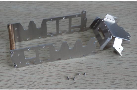
1 Installation Tutorial 1. Remove the finger parts, if the film, tear off the surface of the film, the number of parts were First assemble the big finger parts, use M2X3 screws, M2X6 copper pillar, the first joint of the big finger to use wide parts.


2 Complete the assembly: 3. Assemble the other finger parts still use M2X3 screws, M2X6 copper pillar.


3 Complete the assembly: 4.Followed by the completion of the remaining fingers of the assembly, in addition to big fingers different, the remaining three fingers are the same.


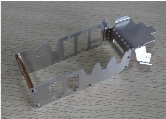
4 5. Next we have the overall assembly. Assemble the copper column, using M2X20 root M2X Parts are in the same bag.
:")

5 6.If the right arm is installed as follows (if left can be skipped): Just assemble the copper column with the arm connected to the use of M2X3 screws.


6 7. Then take out the right palm. Assemble the arm connecting piece with the palm of the hand, using the M1.4 * 3 screws, the 1.4 screws as a self-tapping screws, forced into the aluminum plate. When the screw on the left one, the right one on the first do not tighten, then the remaining two, to be screwed into four screws, and then lock the screws


7 8.If it is left as shown in the installation: Using the same arm parts, pay attention to distinguish between right-handed installation in different ways. Assemble the arm connecting piece with the palm of the hand, using the M1.4 * 3 screws, the 1.4 screws as a self-tapping screws, forced into the aluminum plate. When the screw on the left one, the right one on the first do not tighten, then the remaining two, to be screwed into four screws, and then lock the screws
8

 Installation of the first finger servo, which is M2 * 21 copper pillars")
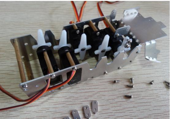
9 9. Left and right arm installation is complete 10. The installation of the right-hand finger servo is as follows (For the left-hand servo install, see step 22): (Note: Before installation, adjust the servo return middle) Installation of the first finger servo, which is M2 * 21 copper pillars with M2 * 18, screws M2 * 6, M2 * 3.


10 11. Screw the screw into the servo mounting hole first, and do not tighten it. 12. And then screw together with the screw into the copper column, this time also tighten the screws, the above is a copper pillar M2 * 21, and the below is M2 * 18.


11 13. Take the second finger servo part, copper column is M2*14 and M2*25. The screw is M2*3 14. Also screw the screw into the mounting hole of the steering gear and do not tighten it.


12 15. Then screw the screw into the copper stud and tighten. The above is M2*14, the below is M2* Take the third finger steering gear parts, in which the screw is still M2*3, the copper column is M2*6.

13 17. Screw the screw into the mounting hole of the steering gear and tighten it with the copper stud. 18. Take the fourth finger servo parts, copper pillars for the M2*14, M2*25. The screw is M2*3. The material is the same as the second finger.


14 Screw the screws in the same way. Then screw the screw into the copper stud and tighten. The above is M2*14, the below is M2*25. As with the second finger actuator, the assembly method is the same.


15 19. Take the fifth finger part, except that there are no blanks. The other parts are the same as the first finger part. The screw is M2*3. The copper pillars are M2*18 and M2*21. Screw in part of the screws M2*3, do not tighten.


16 Into the copper column tighten the screws, the above is M2*21, the below is M2*18 copper pillar. 20. Complete right-hand servo assembly. 21. Note the number of the servo installation for the different fingers.


17 22. If the left-hand steering gear is installed as shown below: Installation of the first finger servo, which is M2*21 copper pillars with M2*18, screws is M2*6 and M2*3. M2*6 screws with the bracket screwed into the servo mounting hole, only part of the screw, do not screw too tight. Finally, the copper column into and tighten the screws. The above is M2*21, the below is M2*18 copper pillar.


18 Subsequent section of the servo installation method with the right-hand steering gear exactly the same. Refer to right-hand Actuator Installation. Complete the installation of the left hand finger servo.


19 According to figures to determine the sequence of each finger servo, do not install errors. 23. The overall installation of the right hand, in the case of left hand Please skip: Install the right-hand finger servo on the right-hand arm in sequence, using the M2*3 screws.


20 Next, install the right-hand 4 5 finger servo. Still use M2*3 screws. Take the cross arm and the screw used to mount the rocker arm. Rocker with a screw directly into the servo. Note that the two long arms of the cross arm have a long side and a short side, the long side is on and the short side is down.


21 Long arm with the steering gear as far as possible to ensure parallel installation and screw into the screw, screw in the end can be screwed, do not continue to screw into, remember to slide easily. If the swing arm is screwed parallel to the steering gear, it can rotate the steering wheel. If it is not parallel, turn the steering arm, then remove the rocker arm, then re-center and re-install the rocker arm. Take the self-tapping screw with the small clamp plate and M2*5. Turn the cable tie plate into the rocker arm, do not twist left margin. The small tip on the platen faces down. Small tip is no practical use only processing side, down is to prevent scratching your fingers.


22 Screw into the longest side of the first arm and 4 holes. Install all tie bars in sequence.


23 Finish close-up, note tip down. Use the M1.4*3 stainless steel screw. The stainless steel screw can not be sucked with a screwdriver, but it is strong and can be used as a self-tapping screw to force the finger into the palm of the hand and secure it. To be screwed, the hand to remove all the fingers, to prevent finger movement when the interference. Take the cable tie with the M2*5 self-tapping screws into the cable tie into the fingers, pay attention to the mouth of a silk mouth down, rocker arm toward the mouth of the rocker arm.


24 Screw the self-tapping screw directly into the head of the cable tie and secure the cable tie.


25 Take M2*23 copper studs and secure with M2*3 screws. Here the use of copper pillars in order to suppress the work of the cable ties, so as not to upturned. Began to adjust the cable ties, start with the big finger, push forward the cable tie fingers upturned, and then push the first finger to ensure that the first steering gear arm with the arm parallel to the side when the fingers can be slightly upturned, Then tighten the 2 screws. And cut, leaving margin, as shown below.


26 And then pull the rocker arm to do the test, this time the first finger to complete debugging. Note: If the steering servo arm is easy to move when the arm is not moving, use the steering gear tester or steering gear control panel to control the rotation, otherwise it is easy to teeth


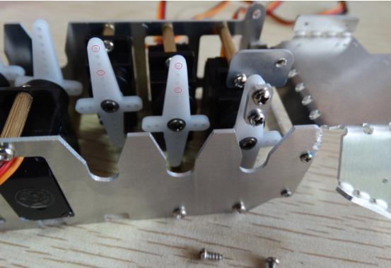
27 Adjust the 2, 3, 4, and 5 finger servos in the same way as the 1st servos. To ensure that two parallel red edge under the fingers slightly upturned, where the maximum straight position for the finger is the maximum stroke position of the steering gear. After the completion of the last back on the back, using four M1.4 * 3 stainless steel screws, the screw as a self-tapping screw forced into. Note that here the first left a screw, right a screw, do not tighten. To be screwed into the other two screws, and other four screws are screwed into the palm of the hand, the last in turn tighten the


28 screws to secure the back of the hand. Here the right hand to complete the assembly. It can be tested by the servo knob or servo control panel. And then in front of the steering gear back to the power supply program.


29 24.Then the overall installation of the left hand, the case of the right hand, please skip: With the right hand, first install servo, using M2* screws. Next install the 4,5 servos and use the M2*3 screws as well.


30 Take the cross arm and the mounting screws for the rocker arm. Rocker with screws screwed into the servo, pay attention to distinguish the long side, long side has long and short. Ensure that the longest edge is on. The longest side of the cross arm faces upwards and ensures that the long side is loaded into the rocker arm in parallel with the servos. As long as the relative parallel can not guarantee absolute parallel.


31 Next remove the platen part and the M2*5 tapping screw. Tip down into the rocker arm, do not tighten, leaving margin. Note that the first and fourth holes are used here.
32


33 Screw on the plate in order to ensure that the tip down. Then take the left-hand part with the M1.4*3 screws. Use 1.4 screws in turn to force the fingers into the palm of the hand and fixed. After fixing your finger, use M2*5 self-tapping screws to secure finger straps. Cable tie in the mouth of the mouth down in the rocker arm toward the rocker arm. Tie the tail into the pressure plate.


34 Adjust the length of the tie, which can refer to the right hand here. Note: If the steering servo is easily moved by hand when moving the rocker arm, use the servo tester or the servo control panel to control the servo rotation.


35 Adjust the cable tie Figure 2 lines remain parallel to the state, the fingers can be slightly upturned, tighten the screws, and cut cable ties and left margin.


36 Take the M2*23 copper studs using two M2*3 screws. After the completion of the last back on the back, using four M1.4 * 3 stainless steel screws, the screw as a self-tapping screw forced into. Note that here the first left a screw, right a screw, do not tighten. To be screwed into the other two screws, and other four screws are screwed into the palm of the hand, the last in turn tighten the screws to secure the back of the hand. Here, the assembly is completed.


37 Left and right hand to complete the finished product map. Note: When using the robot finger, try not to let the small servo for a long time in a large or the smallest position, that is, the fingers hold the straight with the two states, and always pay attention to the small servo heat. If the heat is too large, so that the small steering gear back to the middle of the state, or stop working. Let the steering gear cool down. And re-adjust the length of the lower band.


38 Left hand front and back Right hand front and back:


39 Note that the left and right behind the four M2.5 screw holes, is used to expand the use of connecting the steering gear, generally do not use. Use the time to set into the robot steering gear, and use the M2X6 black, left and right of the two self-tapping screws fixed.
Assembly Instructions 10 X 10 Aluminum Frame Building
 Assembly Instructions 10 X 10 Aluminum Frame Building 27 97 9 8 47 36 74 52 10 10 X 10 Square Building W/ Dome Includes: The Steel Entry Door with a Dead Bolt Lock assembly and Aluminum Door Frame. Metal
Series 1100 Aluminum Door Canopy
 Series 00 Aluminum Door Canopy with Support Arms It is our recommendation that you read instructions carefully prior to assembly and installation. Series 00 with Support Arms MOUNTING BAR (A) TOP TRIM
Pantry IMPORTANT NOTE Carefully remove all the parts from the carton and put them individually on a soft cloth to prevent scratches or oth
 88 5076 691 Pantry IMPORTANT NOTE Carefully remove all the parts from the carton and put them individually on a soft cloth to prevent scratches or other damages occurring to the parts. We have taken great
ABM International, Inc.
 ABM International, Inc. Lightning Stitch required 1 1.0: Parts List head and motor assembly (Qty. 1) Reel stand (Qty. 1) Needle bar frame clamp (Qty. 1) Motor drive (Qty. 1) 2 Cable harness with bracket
Series 1500 Aluminum Door Canopy
 Series 500 Aluminum Door Canopy with Sidewings It is our recommendation that you read instructions carefully prior to assembly and installation. Series 500 with Sidewings mounting bar (A) top trim (B)
Closet Wall Drawer Unit
 88 5531 751 Closet Wall Drawer Unit A. B. C. Shelf D. E. F. For assembly see instructions in carton 88 5531 752. 88 5531 752 Closet Wall Drawer Unit G. H. I. Plinth M. Bottom L. N. 2 pc. J. K. O. Drawer
Assembly Instructions 10 X 10 Aluminum Roof Support
 Assembly Instructions 10 X 10 Aluminum Roof Support Aluminum Roof Support Bolt Package 16-5/16 X 2 ¼ SS Bolt 24-5/16 X 1 SS Bolt 40-5/16 SS Nylon Lock Nuts 16-5/16 SS Flat Washers 28-4 ½ Wood Screws 36-1
ORTOP Modular Robot v3.0 Arm Assembly
 Base Plate Assembly Parts Needed: Arm Assembly BAG 1 2 Socket Head Cap Screw, 1-1/4" 2 Socket Head Cap Screw, 1/2" 2 Button Head Cap Screw, 3/8" 6 Nuts 1 Gear Hub Spacer 1 Flat Building Plate 1 Single
105" TIGER MOTH ARF INSTRUCTION MANUAL VERSION 1.0
 105" TIGER MOTH ARF INSTRUCTION MANUAL VERSION 1.0 Step 1. Installation of the aileron servos 1) Mount aileron servo to servo mounting blocks with servo s screws. Install servo mounting plate with screws.
Spiderbeam Balun Construction Guide
 BALUN CONSTRUCTION GUIDE Ver. 1.0 1 The components of the Balun Kit are in a plastic bag. Most of the components are inside the plastic case of the balun. The aluminum U-profile and the RG-142 Teflon Coax
Replacing the Reciprocator on the SWF Compact Series Machine (601C and 1201C)
") Follow the instructions below to replace the reciprocator in the SWF Compact series machines. The tools required can be found in the tool kit that came with the machine. Preparation 1. First, place the
Follow the instructions below to replace the reciprocator in the SWF Compact series machines. The tools required can be found in the tool kit that came with the machine. Preparation 1. First, place the
Budget Robotics Octabot Assembly Instructions
 Budget Robotics Octabot Assembly Instructions The Budget Robotics Octabot kit is a low-cost 7" diameter servo-driven robot base, ready for expansion. Assembly is simple, and takes less than 15 minutes.
Stainless Steel Bench Stand
 Installation Manual Stainless Steel Bench Stand Product(s): 29600 29601 51229 2016 by Fairbanks Scales, Inc. Revision 2 02/16 All rights reserved. Amendment Record STAINLESS STEEL BENCH STAND Document
ELECTRICAL CARGO BIKE with mechanical disc breaks
 ELECTRICAL CARGO BIKE with mechanical disc breaks SAMLEMANUAL ASSEMBLE MANUAL Read and understand these instructions before you begin the assembly. The bike comes partly assembled, and it is important
BOB SLAY (assembly instructions)
") BOB SLAY (assembly instructions) Items included: 7 x Acrylic cutouts labeled A-G 1 x Acrylic IO Panel 1 x Acrylic locking plate of PCI cards 2 x Acrylic 5.25 spacers 2 x momentary switches (power/reset)
BOB SLAY (assembly instructions) Items included: 7 x Acrylic cutouts labeled A-G 1 x Acrylic IO Panel 1 x Acrylic locking plate of PCI cards 2 x Acrylic 5.25 spacers 2 x momentary switches (power/reset)
SERVICE MANUAL AND PARTSLIST
 SERVICE MANUAL AND PARTSLIST Next 20 CONTENTS WHAT TO DO WHEN... 1~3 SERVICE ACCESS FACE COVER... 4 TOP COVER... 4 BASE COVER... 5 REAR COVER... 6 FRONT COVER... 7 MECHANICAL ADJUSTMENT NEEDLE THREAD TENSION...
TITAN2-EDGE Public Access Computer Station Dual Track
 TITAN2-EDGE Public Access Computer Station Dual Track TITAN2-EDGE Rev A 6/17 Model TITAN2-EDGE ASSEMBLY AND ADJUSTMENT TITAN2-EDGE PARTS AND TOOLS PLEASE REVIEW these instructions before beginning the
RH-412 STEEL DOORS INSTALLATION INSTRUCTIONS
 RH-412 STEEL DOORS INSTALLATION INSTRUCTIONS By following the steps outlined below, the assembly, installation and adjustment of the steel doors, will be a simple process. Let s start with the Driver Side.
INSTALLATION INSTRUCTIONS RH 412 STEEL DOORS
 By following the steps outlined below, the assembly, installation and adjustment of the steel doors, will be a simple process. Let s start with the Driver Side. Note: Having the hood open makes the job
MODEL 200/220 ASSEMBLY INSTRUCTIONS
 V-Twin MFG. Coats Tire Changer VT Part No. 16-0510 This tool should only be used by a knowledgeable and trained motorcycle technician V-Twin Mfg. accepts no responsibility for improper use. MODEL 200/220
EDGE2 DUAL MONITOR ARM
 EDGE2 DUAL MONITOR ARM EDGE2 Rev A 2/17 Model EDGE2-SLV Model EDGE2-BLK Model EDGE2-WHT ASSEMBLY AND ADJUSTMENT EDGE2 DUAL MONITOR ARM PARTS AND TOOLS PLEASE REVIEW these instructions before beginning
3. X-axis assembly. 3. X-axis assembly. Written By: Jakub Dolezal manual.prusa3d.com/ Page 1 of 13
 3. X-axis assembly Written By: Jakub Dolezal 2018 manual.prusa3d.com/ Page 1 of 13 Step 1 Tools necessary for this chapter Needle-nose pliers for zip tie trimming. 2.5mm Allen key for M3 screws 2mm Allen
Assembly Guide Robokits India
 Robotic Arm 5 DOF Assembly Guide Robokits India info@robokits.co.in Robokits World http://www.robokitsworld.com http://www.robokitsworld.com Page 1 Overview : 5 DOF Robotic Arm from Robokits is a robotic
Item # Thanks for shopping with Improvements!
 Thanks for shopping with Improvements! Hampshire -Door Cabinet Item #5505 To order, call -800-64- West Chester, OH 45069 Made in China PR-6 If you have questions regarding this product, call -800-64- Mon.-Fri.
ABM International, Inc. Navigator Assembly Manual
 ABM International, Inc. 1 1.0: Parts List Tablet (Qty. 1) Tablet mount (Qty. 1) NOTE: Mount may appear and operate different then image below Control Box (Qty. 1) Motor Power Supply (Qty. 1) 2 X-axis motor
25000 Series Lo-T TM Butterfly Control Valve Instructions
 November 2001 25000 Series Lo-T TM Butterfly Control Valve Instructions Instruction No. 25.1:IM PRELIMINARY STEPS Before installation, note the flow direction arrow on the valve body. The flow should enter
Assembly Instructions: AM-10 Hand & Foot Cycle Early Intervention Part #: 50-HFC-0105
 Assembly Instructions: AM-10 Hand & Foot Cycle Early Intervention Part #: 50-HFC-0105 Refer to the following instructions on how to assemble your tryke. Study the instructions carefully before beginning
INSTALLATION GUIDE 2009-CURRENT HUMMER H3T PRODUCT CODE:
 INSTALLATION GUIDE 2009-CURRENT HUMMER H3T PRODUCT CODE: 268 June 22, 2010 TOOLS NEEDED COMPONENTS INCLUDED P2 Tip 3/8" Drill Rubber Gasket(s) x 2 Bracket(s) x 2 1/2" Drill Bit Bulkhead Flange #2 Phillips
7878 K940. Checkpoint Antenna. Kit Instructions. Issue B
 7878 K940 Checkpoint Antenna Kit Instructions Issue B Revision Record Issue Date Remarks A July 7, 2009 First issue B Nov2013 Revised the Checkpoint installation procedures for 7878 and 7874 scanners Added
ASSEMBLY AND ADJUSTMENT
 EDGE MONITOR ARM EDGE Rev A 2/17 Model EDGE-SLV Model EDGE-BLK Model EDGE-WHT ASSEMBLY AND ADJUSTMENT EDGE MONITOR ARM PARTS AND TOOLS PLEASE REVIEW these instructions before beginning the assembly and
Code Product Qty 1 Top Vertex 3 2 Hot End Housing 1 3 Bottom Vertex 3 4 Print Platform Lock 3 5 End Stop Holder 3 6 Filament Feeder Motor Bracket 1 7
 List of Parts Code Product Qty 1 680mm Extrusion 3 2 Power Supply 1 3 240mm Extrusion 9 4 42mm Nema 17 Stepper Motor 3 5 Slider-Hotend Connecting Rod 6 6 48mm Nema 17 Stepper Motor 1 7 Linear Rail with
WPS crew Doors Installation instructions
 WPS-132-133 crew Doors Installation instructions ORDER OF INSTALLATION FOR A COMPLETE ENCLOSURE OF A CREW WPS (Weather Protection System) IS AS FOLLOWS: 1. Heater 2. Rear Thresholds - Right Hand & Left
Bend-Tech Dragon Assembly Manual
 p.1 Bend-Tech Dragon Assembly Manual IMPORTANT: Please read before unpacking. Place shipping container in a wide open area where you will have room to work and assemble this product. Shipping The Dragon
Quill Stop V2 Installation Guide 11/16/2014
 Thank you for purchasing the Quill Stop for the Sieg X3 (Grizzly G0463) and SX3 (Grizzly G0619) mills. Your feedback is always appreciated. Please email questions and comments to gregpriest@cox.net. What
Installation Instructions for FC2 & FC15 Forward Controls for the Super Magna
 Installation Instructions for FC2 & FC15 Forward Controls for the Super Magna It is highly recommended that you use a thread lock compound such as Loctite brand on all threads to keep them from vibrating
HQ Precision-Glide Track Upgrade 2 Extension Kit for HQ Studio Frame Part# QF09750
 HQ Precision-Glide Track Upgrade 2 Extension Kit for HQ Studio Frame Part# QF09750 Important Note: Upgrading the track system on the HQ Studio Frame requires the use of this 2 Extension Kit (Part #QF09750),
The Nomenclature and Geometry of LEGO
 The Nomenclature and Geometry of LEGO AN OVERVIEW OF LEGO EV3 MINDSTORMS ELEMENTS AND HOW THEY WORK TOGETHER UPDATED 9/27/2015 Required Stuff Please do not wander the building. Rest Rooms Location. Food
TIGER MOTH 120 ASSEMBLY INSTRUCTIONS
 TIGER MOTH 120 ASSEMBLY INSTRUCTIONS SPECIFICATIONS Wing Span: Length: Radio: Flying Weight: 1920mm 1580mm 4 channel with 6 servos 4200g AILERON ASSEMBLY 1 Start by removing the servo cover from the bottom
Installation and Assembly - Universal Articulating Swivel Double-Arm for 42" - 60" Plasma Screens
 Installation and Assembly - Universal Articulating Swivel Double-Arm for 42" - 60" Plasma Screens Models: PLAV 70-UNL, PLAV 70-UNL-S PLAV 70-UNLP, PLAV 70-UNLP-S R This product is UL Listed. It must be
BY ALIEN TECHNOLOGIES CORP
 BY ALIEN TECHNOLOGIES CORP Assembly Instructions TopLift Pros YOU MAY ALSO REVIEW OUR ASSEMBLY VIDEO, PLAY AND PAUSE AT YOUR CONVENIENCE. JUST VISIT US AT WWW.TOPLIFTPROS.COM AND GO TO Customer Support
E-FLIGHT BLADE CX COMPLETE DISASSEMBLY JANUARY 2006
 E-FLIGHT BLADE CX COMPLETE DISASSEMBLY JANUARY 2006 AERONUTS THIS IS NOT AN OFFICIAL E-FLIGHT MANUAL OR INSTRUCTION. IT IS BEING PROVIDED FOR INFORMATIONAL PURPOSES ONLY. AUTHOR ASSUMES NO LIABILITY FOR
Kontax Stirling Engines KS90T instructions
 Kontax Stirling Engines KS90T instructions This document covers the following: Tools required Parts list Assembly instructions Operating instructions Maintenance Contact details: www.stirlingengine.co.uk
Baby Grande or Grande Crank Shade with Cables and Housing Installation Instructions
 Baby Grande or Grande Crank Shade with Cables and Housing Installation Instructions Tools Needed Drill 3/8 Metal Drill Bit Screwdriver (Flat & Phillips) Measuring Tape Pencil 4 Level Plumb Line ¼ Masonry
Durst Laborator 138 S
 Durst Laborator 138 S -I- G139 Durst Laborator 138 S Durst Laborator G 139 Servicing instructions L 1 3 8 S G 139 - Replacing the counterweight spring The special tool required for this purpose is supplied
All American Mower Blade Sharpener Mulching Blade Model Patent Pending
 All American Mower Blade Sharpener Mulching Blade Model 5000 Patent Pending Revised May 3, 2017 Attaching the guide pin to your grinder: Assembly and Use Locate the guide pin (included with the sharpener)
INSTALLATION INSTRUCTIONS FOR SL-LB MANUAL LIFT BARRIER GATE ARMS
 INSTALLATION INSTRUCTIONS FOR SL-LB MANUAL LIFT BARRIER GATE ARMS Questions? Call 520-780-9751 or visit our website at: www.barriergatearm.com YOUR SL-LB MANUAL LIFT BARRIER GATE ARM WILL ARRIVE WITH WEIGHT
Aluminum Sprinter Rack Installation
 INSTALLATION INSTRUCTIONS MyGlassTruck.com Division of Demountable Concepts, Inc Aluminum MyGlassTruck.Com Demountable Concepts, Inc. 200 Acorn Rd. Glassboro, NJ 08028 800.254.3643 toll free 856.863.0900
3.2.3 Rear Door Window and Quarter Window Carrier Assembly
 Tighten all bolts. Tighten bolts marked -1- and -2- in specified sequence. Tightening torque: 8 Nm Remaining bolts can be tightened in any sequence. Insert door window -3- through window recess without
Special Z-Axis Ballscrew Replacement
 To replace Z-axis ballscrew without removing X-axis components When rebuilding an OmniTurn slide, all the precision components are replaced. The tooling plate and saddle are removed to gain access to the
Due to possible damage in shipping, the vertical stop assembly has been removed from this machine.
 Due to possible damage in shipping, the vertical stop assembly has been removed from this machine. To assemble, insert the threaded rod through the shroud opening in the top of the machine. Start the four
Castle Frame Assembly Table AT-8. Diagnostics Manual. Castle, Inc. Petaluma, CA
 Castle Frame Assembly Table AT-8 Diagnostics Manual Castle, Inc. Petaluma, CA 800-282-8338 Solutions Index Adjusting the Tabletop.. 8.01 Adjusting the Fence... 8.02 Aligning the Arm... 8.10 Adjusting Bracket..
Installation and Assembly - Universal Articulating Swivel Double-Arm for 42" - 60" Plasma Screens
 Installation and Assembly - Universal Articulating Swivel Double-Arm for 42" - 60" Plasma Screens Models: PLAV 70-UNL, PLAV 70-UNL-S PLAV 70-UNLP, PLAV 70-UNLP-S R This product is UL Listed. It must be
H2-50 Hydrogen Generator Field Update
 This field update is intended to provide extra protection in the event the H2 generation cell fractures or cracks. Please add the additional parts to your H2-50 as soon as possible. Please take a digital
Assembly Instructions: Bencher Skylark
 Assembly Instructions: Bencher Skylark Tools Required: Pop Rivet Tool Tape Measure Hex Wrenches Screwdriver Several Disposable Rags Two Saw Horses Several boxes or bowls to hold fasteners and small parts
Step 1: The tools you will need: 1x Phillips Screwdriver 1x Vending Machine key
 2 3 The tools you will need: 1x Phillips Screwdriver 1x Vending Machine key Step 1: Open the boxes and inventory each of the parts before assembling. Each stand will consist of 1 16 inch Round Base, 1
SAFETY INSTRUCTIONS. Wear protective clothing, including safety glasses and steel toe boots.
 SAFETY INSTRUCTIONS Wear protective clothing, including safety glasses and steel toe boots. DO NOT allow loose clothing or long hair near machine operations. Keep work site and machine clean. Use brush
RC-TEK Ltd. SKYSHARK 450 REFERENCE MANUAL. Copyright 2007 RC-TEK, All Rights Reserved
 RC-TEK Ltd. SKYSHARK 450 REFERENCE MANUAL Frame Assembly On each page of this manual the parts required for each step will be listed below along with a set of images showing the stages of each part of
BO 76 SAFETY PAD. Ex. Coupe COMPONENTS
 BO76 SAFETY PAD Ex. Coupe COMPONENTS BO77 COMPONENTS (Cont d) BO78 REMOVAL OF SAFETY PAD (See page BO76, 77) 1. DISCONNECT BATTERY CABLE FROM NEGATIVE TERMINAL 2. REMOVE STEERING WHEEL (See page SR3) 3.
ATLAS SERIES 800 SPIN/SPIN TOOLS
 ATLAS SERIES 800 SPIN/SPIN TOOLS Totally pneumatic. Installs Atlas SpinTite and pre-bulbed Plus+Tite fasteners into various material thickness. Lightweight, easy to handle. A Nose Assembly (AENP) Components
3DOF Leg Kit Assembly Guide VERSION 1.0
 3DOF Leg Kit Assembly Guide VERSION 1.0 WARRANTY CrustCrawler warrants its products against defects in materials and workmanship for a period of 30 days. If you discover a defect, CrustCrawler will, at
Display-Top Apothecary Cabinet. Assembly Instructions. Page 1
 Display-Top Apothecary Cabinet Assembly Instructions Page 1 Display-Top Apothecary Cabinet Parts List Please check packaging for all parts and hardware before discarding. Unpack and lay parts on clean,
CHAPTER 8. Through Dovetail Procedures
 CHAPTER Through Dovetail Procedures 52 Chapter D4 User Guide THROUGH DOVETAIL PROCEDURES Chapter Foreword In these instructions for using the Leigh Dovetail Jig, we have recommended using certain cutters
FABA. Installation Instructions. Conductor Bar System. Publication #FABA-03 3/1/04 Part Number: Copyright 2004 Electromotive Systems
 FABA Conductor Bar System Installation Instructions Publication #FABA-03 3/1/04 Part Number: 005-1062 Copyright 2004 Electromotive Systems 1S 100 Z Installation Instructions Contents: Basic Diagram - -
EXIT DEVICE OPERATION FIRE DOOR LABELS, STRIKES AND FRAME SCREWS FOR INFORMATION CALL OR VISIT RITEDOOR.COM
 RECORD & LABELS WHAT THIS OWNER'S CAN DO FOR YOU It explains exactly how The Rite Door operates. It explains periodic maintenance requirements necessary to assure reliable operation. It explains simple
Lumber Smith. Assembly Manual. If you are having problems assembling the saw and need assistance, please contact us at:
 Lumber Smith Assembly Manual If you are having problems assembling the saw and need assistance, please contact us at: 804-577-7398 info@lumbersmith.com 1 Step 1 Safety Carefully read the Owners Manual.
HFp. User s Guide. Vertical. entenna. 7 MHz 30 MHz Amateur Radio Antenna Plus 6-Meters
 User s Guide HFp Vertical 7 MHz 30 MHz Amateur Radio Antenna Plus 6-Meters The Ventenna Co. LLC P.O. Box 2998, Citrus Heights, CA, 956 www.ventenna.com entenna Table of Contents The HFp Antenna -------------------------------------------------------------------
re3d Assembling Gigabot: "Flatpack"
 re3d Assembling Gigabot: "Flatpack" Your Gigabot was assembled, calibrated, tested, and taken apart for shipping purposes. All you need to do is reassemble it, and you're ready to go! Written By: Chris
1 of 2 3/3/2017 4:49 PM
 1 of 2 3/3/2017 4:49 PM Front Door Window, Assembly Overview 1 - Window guide - Inserted on flange 2 - Door 3 - Inner window recess seal - Inserted on flange 4 - Bolt - 20 Nm 5 - Carrier assembly - Window
Heacent 3D printer assembly manual. Prusa i3
 Heacent 3D printer assembly manual Prusa i3 Y-axis assembly 1. Y axis motor section: Find the belowing parts bag, Y-axis motor Assembled parts are separated as shown below, note that the motor between
Installing flat panels on the MPL15 wall mount
 Installing flat panels on the MPL15 wall mount The MPL15 (DS-VW775) is a full-service video wall mount that can accommodate tiled LCD panels with up to a 400 x 400 mm VESA pattern in portrait and landscape
TOYOTA TACOMA TRAILER WIRE HARNESS Preparation
 Preparation Part Number: PT725-35120 Kit Contents Item Quantity Reqd. Description # 1 1 Flasher Assembly (F/A) 2 1 Wire Harness 3 1 Sub Wire Harness 4 2 Plastic Tie (300mm) 5 4 Plastic Tie (200mm) 6 13
V4 Premium Kit. Prusa i3 Build Guide
 V4 Premium Kit Prusa i3 Build Guide Hi! Congratulations on your purchase of the DIYElectronics.co.za Prusa I3 kit, the best South African 3D Printer Kit! Hopefully this should serve as complete guide to
Mini Cooper Lock Actuator
 2001-2006 Mini Cooper Lock Actuator Replacement This guide is on how to remove the lock actuator from the cars door. Written By: Jem ifixit CC BY-NC-SA www.ifixit.com Page 1 of 13 INTRODUCTION In order
VISUAL GUIDE MANUAL DRO INSTALLATION ON LATHE / TURNING MACHINE. By ebay ID: TheDroStore
 VISUAL GUIDE MANUAL DRO INSTALLATION ON LATHE / TURNING MACHINE By ebay: TheDroStore info@thedrostore.com 1 2. Basic Installation Principles scale should be centered and be aligned such that it could cover
ASSEMBLY AND ADJUSTMENT
 EPPA MONITOR ARM EPPA Rev A 10/17 Model EPPA-XXX ASSEMBLY AND ADJUSTMENT EPPA MONITOR ARM PARTS AND TOOLS PLEASE REVIEW these instructions before beginning the assembly and adjustment procedures. Check
Copyright 2007 MLCS 1
 Copyright 2007 MLCS 1 REFERENCE GUIDE and SPECIFICATIONS: Edge Guides: This 12 Dovetail Template comes complete with 2 Edge Guide Sets one set for Half Blind and one set for Rabbeted Half Blind Dovetails.
1. Begin by rolling your window up all the way 2. Remove your door and window handles by unscrewing the flat head set screws behind each handle.
 1. Begin by rolling your window up all the way 2. Remove your door and window handles by unscrewing the flat head set screws behind each handle. 3. Remove the 12 screws that attach the steel interior door
Kossel Rev B Build Guide V1.0
 Kossel Rev B Build Guide V1.0 1 Table of Contents: Step 1: BASE ASSEMBLY Gathering parts: Building the Corners and Base: Step 2: UPPER ASSEMBLY Building Upper: Step 3: VERTICAL RAIL INSTALLATION Building
SwingSafe Swing-Away Mailbox Support Diagram
 SwingSafe Swing-Away Mailbox Support Diagram Wood Mounting Plates Top Arm (B) Muffler Clamps (A) Carriage Bolts and Nuts Bottom Arm 4-Foot U-Channel Post USPS Recommended 42-44 Height Ground Slope Hex
Hollywood Swing Away 2 and 4 Bike Racks Assembly and Installation Guide
 Hollywood Swing Away 2 and 4 Bike Racks Assembly and Installation Guide Tools Required: two adjustable wrenches, pliers, ¾ socket wrench recommended Note: please do assembly near your vehicle as you Can
Technical Training USG Saw Chain Grinder
 Technical Training USG Saw Chain Grinder 1 USG HOS The STIHL USG Universal Sharpener will sharpen all types of saw chain. This is by far the most versatile and accurate machine of its type on the market.
Woodline USA Woodline Spacer Fence System
 Woodline USA Woodline Spacer Fence System MADE IN THE USA Includes: (1) ¼ Spacer Fence (1) 3/8 Spacer Fence (1) ½ Spacer Fence (1) Hardware Package (1) 3 Piece Brass bar set (2) Setup Blocks Visit Us Online
c. Pins, bolts, and retaining rings b. Washers, locking nuts, and rivets
 62 20 HW 8: Fasteners / Force, Pressure, Density Mechanical Systems DUE Mon, 11/21/16 Start of class Check link on website for helpful fastener information Please use a scantron. Material is based primarily
HURST COMP STICK KIT DODGE CHARGER, MAGNUM, AND CHRYSLER 300 (with AUTO-STICK) Catalog # & by Hurst Performance
 Catalog # & by Hurst Performance") HURST COMP STICK KIT 2005-2007 DODGE CHARGER, MAGNUM, AND CHRYSLER 300 (with AUTO-STICK) Catalog #538 0410 & 538 0411 2009 by Hurst Performance FORM 159 0410 03/09 Thank you for purchasing the Hurst Comp
HURST COMP STICK KIT 2005-2007 DODGE CHARGER, MAGNUM, AND CHRYSLER 300 (with AUTO-STICK) Catalog #538 0410 & 538 0411 2009 by Hurst Performance FORM 159 0410 03/09 Thank you for purchasing the Hurst Comp
TS4001. Model # 10 inch Table Saw addendum SETUP & OPERATION MANUAL
 SETUP & OPERATION MANUAL Features Powerful 13 amp motor Cast aluminum work table Riving knife Anti-kickback pawls Includes: 10 in. 24 tooth tungsten carbide tipped saw blade Rip fence Miter gauge Push
INSTALLATION INSTRUCTION FOR HIDDEN TAILGATE LATCHES ON GM STEPSIDE TRUCKS
 INSTALLATION INSTRUCTION FOR HIDDEN TAILGATE LATCHES ON 41-87 GM STEPSIDE TRUCKS This instruction covers the installation of the hidden tailgate latches for the 41-87 GM Stepside trucks. Follow along as
flipit Monitor Mount Assembly
 flipit Monitor Mount Assembly These instructions are for assembling the flipit Monitor Mount into a factory made SMARTdesks product. For instructional clarity, some panels appear as a light color. Actual
FINGER JOINT TEMPLATES LEIGH DEDICATED CUSTOMER SUPPORT Using the F3, F18 and F24 Finger Joint Templates on Leigh D-Series & SuperJigs
 LEIGH FINGER JOINT TEMPLATES Using the F, F and F Finger Joint Templates on Leigh D-Series & SuperJigs DEDICATED CUSTOMER SUPPORT -00-- ii Introduction F, F & F FINGER JOINT TEMPLATES USERGUIDE FOREWORD
Spindle Drive Belt - Tension Adjustment - Gates Sonic Meter
 Spindle Drive Belt - Tension Adjustment - Gates Sonic Meter - Lathe LAST UPDATED: 09/19/2018 Spindle Drive Belt - Tension Adjustment - Gates Sonic Meter 1 Change the units to lbf, as follows: Hold [0]
Clearview Railing System Installation Instructions
 Clearview Railing System Installation Instructions Disclaimer: AGS Stainless, Inc. has its Clearview Railing Systems designed by a professional engineer to meet the requirements of the latest national
INSTALL INSTRUCTIONS
 Jeep JK Rear Stealth Bumper Product : 508R0B, 508R0B TC Applica on : 2007+ Jeep Wrangler JK ( 2 Door and 4 Door ) Page ( 1 of 5 ) I WARNING Read the instruc ons completely before beginning installa on.
Sunrise Deck Assembly Instructions for Kingston Left
 Sunrise Deck Assembly Instructions for Kingston Left It s easiest to build the deck frame first like it will be lying on its back and then after all 4 legs and horizontals are in place, tip the deck toward
Installing the Partridge RA Extension on Losmandy G11
 Installing the Partridge RA Extension on Losmandy G11 Michael Herman July 20, 2015 Tools: 3/16 inch hex key (allen wrench) [If desired for DEC indicator ring friction improvement: flat screwdriver, and
INSTALLATION INSTRUCTIONS CHEVY C-10 INDEPENDENT FRONT SUSPENSION
 INSTALLATION INSTRUCTIONS 73-87 CHEVY C-10 INDEPENDENT FRONT SUSPENSION Please read these instructions completely before starting your installation. Assemble suspension on vehicle before powder-coating
The wick in your heater needs replacing if, after repeated cleanings, any of the following conditions still exist:
 WICK REPLACEMENT The wick in your heater needs replacing if, after repeated cleanings, any of the following conditions still exist: Slow to light, hard movement of the wick adjuster knob, kerosene odor
Baby Grande or Grande Crank Shade with Cables and Housing Installation Instructions
 Baby Grande or Grande Crank Shade with Cables and Housing Installation Instructions Tools Needed Drill 3/8 Metal Drill Bit Screwdriver (Flat & Phillips) Measuring Tape Pencil 4 Level Plumb Line ¼ Masonry
Dragon A400 Assembly Manual
 1 Dragon A400 Assembly Manual Crate Size: 120 L x 65 W x 80 H Machine Size (After Assembly): 372 L x 30 W x 72 H The Dragon A400 will arrive in its crate and will need to be opened with a minimum of two
Kontax Stirling Engines KS90 instructions
 Kontax Stirling Engines KS90 instructions This document covers the following: Tools required Parts list Assembly instructions Operating instructions Maintenance Contact details: www.stirlingengine.co.uk
Installation and Assembly: Articulating Swivel Arm for 37" - 60" Flat Panel Displays
 Installation and Assembly: Articulating Swivel Arm for 37" - 60" Flat Panel Displays Models: PLA60, PLA60-S, PLAV60, PLAV60-S Max UL Load Capacity: 175 lb (79 kg) 2300 White Oak Circle Aurora, Il 60502
OPERATING INSTRUCTIONS MODULGRAV. Tel. +49 (0) Fax +49 (0) homepage:
 Fax +49 (0) homepage:") OPERATING INSTRUCTIONS MODULGRAV Kolpingstraße -7 D-784 Singen / Htwl. Postfach 80 D-784 Singen / Htwl. Tel. +49 (0) 77 88-0 Fax +49 (0) 77 88 66 e-mail: info@elma-ultrasonic.com homepage: www.elma-ultrasonic.com
OPERATING INSTRUCTIONS MODULGRAV Kolpingstraße -7 D-784 Singen / Htwl. Postfach 80 D-784 Singen / Htwl. Tel. +49 (0) 77 88-0 Fax +49 (0) 77 88 66 e-mail: info@elma-ultrasonic.com homepage: www.elma-ultrasonic.com