The Nomenclature and Geometry of LEGO
|
|
|
- Martin Blake
- 6 years ago
- Views:
Transcription


1 The Nomenclature and Geometry of LEGO AN OVERVIEW OF LEGO EV3 MINDSTORMS ELEMENTS AND HOW THEY WORK TOGETHER UPDATED 9/27/2015
2 Required Stuff Please do not wander the building. Rest Rooms Location. Food and Drink. Cell phones 2


3 WARNING CHOKING HAZARD Do NOT put LEGO blocks or pieces in you mouth for any reason. Not only is it gross, they just don t taste good. Also no LEGO pieces in your nose, ears, eyes or anywhere else they don t belong. 3
4 Introduction Annual production of Lego bricks averages approximately 36 billion per year, or about 1140 elements per second. Since 1958, more than 400 billion Lego pieces have been produced, or 86 for every person in the world! There are roughly 4,200 different Lego elements in 58 different colors. Same piece, many different names Same piece, many different colors 4
5 Hands-on Exercises Parts List Qty Item P/N 8 Friction Peg Beam 11M Peg 3M Beam 5M x5 90 beam Beam 7M Cross Axle 2M Technic Cross Block 2x Technic Cross Block 2x Qty Item P/N 2 Axle 5M Double cross block z gear z gear Axle 3M Axle 4M Bionicle eye Half bushing Bushing Non-friction pegs


6 LEGO Mindstorms EV3 kit The LEGO Technic elements in the Mindstorms sets are: Electronic elements Beams Pegs and axle pegs Axles and connectors Gears Wheels Decorative elements Miscellaneous elements 6
7 Electronic elements Intelligent Brick Drive motors Touch sensor Color sensor Ultrasonic sensor Gyroscope Connector cables 7
 Released")
8 Intelligent Bricks History EV3 NXT Educational released August 1, 2013 Commercial released September 1, 2013 Released 2006 RCX (Robotic Command explorers) Released

")


9 Sensors : EV3 Touch Sensors (2) : EV3 Color Sensor : Gyro : Ultrasonic Sensor 9


10 Drive Motors : EV3 drive motor : Medium motor 10
11 Beams Straight beams Angular beams Frames Thin beams Links 11
12 Beams - Straight Beams are measured by counting the number of holes. Beams come in odd numbers when counting the holes, with one exception. Beams start with15 holes and go down in size by two holes to the 3 hole beam and include one even-numbered beam with 2 holes. The number of holes corresponds to the length of the beam in Fundamental LEGO Units or Modules (1M is 8mm). 12

13 Beams - Straight 3M Beam 5M Beam 7M Beam 9M Beam 11M Beam 13M Beam 15M Beam 13
14 Tip for determining beam size. To quickly determine the size of the longer beams: place a finger on the middle hole of the beam, then you can quickly count how many holes are on one side, double it, and add one

15 Specialty beams : Horizontal to Vertical Beam 90 Degrees : Beam 1X2 with Cross And Hole : Cross Block 3X2 15
16 Pegs and Axle Pegs Pegs are like the nails, screws, and bolts of LEGO Mindstorms, they hold things together. Pegs fit in the beam holes. Two primary groups of pegs: Friction Non-Friction 16


17 Pegs and Axle Pegs Friction : Connector Peg with Friction : 2M Friction Snap with Cross Hole : 3M Connector Peg with Friction : Connector with Friction Cross axle : Ball With Friction Snap*

18 Pegs and Axle Pegs Non-friction : Connector peg : 3M Connector peg : Connector peg Cross Axle
19 Identifying friction and non-friction pegs Friction pegs have ridges that help to create friction with the beams. Non-Friction pegs are smooth. 19


20 Beams and snap combinations : Beam 3M with 4 Snaps : Angular Beam 90 with 4 Snaps 20
21 Using Beams and Pegs Hands-on activity 21

22 Extending Beams Using two black pegs with friction connect two beams using the two end holes of each beam. Test: Holding the ends of the extended beam gently flex it. Result: The beam is straight but still has some flex. 22

23 Extending Beams Using the same two black pegs with friction, overlap the beams five holes. Test: Holding the ends of the extended beam gently flex it. Result: Structure is more rigid. Note: Adding additional black pegs will hold the beams together better, but not required for strength. 23
24 Increasing Strength by Making Wider Using two 3M blue pegs with friction, overlap the beams five holes. Then add an additional beam on the pegs extending. Result: A more ridged structure. Note: Alternate the direction of the 3M blue peg ridge to reduce separation. Peg ridge can be used to help in keeping pegs in place on removable attachments. 24

25 Angular beams An angular beam with three holes before and seven holes after the bend is a 3x7 angular beam. 3x5 90º angular beam has holes at both ends. 2x4 90º angular beam has a hole at one end and cross hole at the other. All other angular beams have cross holes at the ends. 25


 / 4585040")

26 Angular beams : Angular Beam 4X : Angular Beam 3X5 90 (Med. Grey) / (White) : Angular Beam 3X : Angular Beam 4X4 26


27 Angular beams : Double Angular Beam 3X : Technic Angular Beam 4X : T-Beam 3X3 with Hole 27

28 Angular combinations 28

29 Frames Frames are referred to based on their shape: O frame H frame Frames add strength to structures : Beam Frame 5X : Beam Frame 5X7 29


30 Thin beams Are half the width of a normal beam. Useful for adding functions or styling to your robots : Triangle : Lever 1X4, Without Notch : Technic Lever 3X3M, 90* : Technic 5M Half Beam* 30
31 Structural frames Hands-on activity 31


32 Make a Structural Frame Using two 11M beams, two 5M beam, and four black pegs, make a structural frame as shown. 32


33 Strength Test of Structural Frame Hold the bottom and press on one side of the frame. What happens to the frame? HOLD 33


34 Adding Strength to the Structural Frame Using two 11M beams, two 3X5 90 angular beams, and six black pegs, make a structural frame as shown. Hold the bottom and press on one side of the frame. What happens to the frame this time? 34

35 Reinforcing with angles A beam angled between the two beams will also improve the structural strength. 35
36 Axles and connectors Axles Bushings Cross blocks 36
. The even number axles are typically black (4, 6, 8M axle).")
37 Axles Length is same as a Lego brick, the smallest is called a 2M axle (with groove) and commonly red or black. The odd number axles are typically grey (3, 5, 7M axle). The even number axles are typically black (4, 6, 8M axle). 37


38 Specialty Axles Axle with end stop Cross axle with end stop Cross axle with end knob : 5.5M Double Cross Axle : Cross Axle 4M With End Stop : Cross Axle 8M With End Stop : Cross Axle 3M with End Knob 38

39 Bushings : Half Bushing for Cross Axle : Bushing for Cross Axle : Double Bushing 3M Bushings can be used as spacers to prevent tires from hitting beams or other structures. 39


 4162857")
")

40 Cross blocks Cross Block Double Cross Block Technic Cross Block 2X1 (Mickey) Technic Cross Block Fork 2X2 (Minnie) Technic Cross Block 90, 2X3 40


41 Cross blocks combinations Using this cross block combination allows mounting two beams at a right angle. 41


42 Cross blocks combinations This cross block combination allows two beams to be mounted smooth sides together. 42


43 Cross block combinations This combination of cross blocks also allows mounting two beams at a right angle. 43


44 Tip for removing small cross axle connector Use long axle to push small axle through Brick Separator 44
45 Cross blocks Hands-on activity 45
46 Cross blocks: Hands-on parts needed 7M beams (2) Technic Cross Block 2X1 (Mickey) (2) Technic Cross Block Fork 2X2 (Minnie) (2) Black peg with Friction (8) 2M Cross Axle with Groove (2) 46
47 Cross block building instructions Align Technic Cross Block 2X1 (Mickey) with Technic Cross Block Fork 2X2 (Minnie). Insert 2M Cross Axle with Groove. Repeat to make a second cross block assembly. 47

48 Cross block building instructions Insert four black pegs into the cross block assembly. Repeat on second cross block assembly. 48
49 Cross blocks building Instructions Place two 7M beams on cross blocks. 49
50 Bracing LEGO pieces are designed to separate when pulled. When intentional it is called disassembly. Sometimes assemblies pull apart unintentionally simply sitting there or while operating. This is called structural failure. One solution is bracing. Bracing can add strength with minimum weight increase. 50


51 Additional cross blocks : Cross Block 3M : 3-Branch Cross Axle Cross Hole : Cross Block 3X2 51

52 Bracing Sample 1 Bracing uses combinations of LEGO part at right angles. 52
53 Bracing Sample 2 Step 1 Step 2 53


54 Bracing Sample 2 Step 3 54
55 Bracing Hands-on activity 55
56 Bracing: Hands-on parts needed 11M beams (3 ea.) 5M beam (1 ea.) Double cross block (2 ea.) 5M axle (2 ea.) Black peg with friction (2 ea.) 56
57 Bracing: Hands-on Step 1 Step 2 Step 3 57

![[1] 4107783: Angle](/docs-images/74/70968306/images/58-3.jpg "Element, 180 Degrees [2]")


58 Axle connectors : Angle Element, 0 Degrees [1] : Angle Element, 180 Degrees [2] : Angle Element, 90 Degrees [6] : Cross Axle, Extension, 2M : Tube W/Double Ø
59 Gears Gears are rotating parts with teeth that mesh with other parts with teeth. LEGO gears are identified by the number of teeth followed by a z. Most gears are 1M thick Combination Reference: 59


60 Gears Gear Wheel 8z Double Conical Wheel 12z Gear Wheel 16z Gear Wheel 24z Gear Wheel 40z 60


61 Gears Conical Wheel 12z Gear Wheel 16z Double Conical Wheel 20z 1M Worm gear Double Conical Wheel 36z 61
62 Gear combinations Teeth :1 1:3 1:5 12 3:5 1:3 16 1:1 20 5:6 24 1:1 3: :1 Stable combination Unstable combination Unknown Combination 62


63 Gear combinations 24z to 24z (1:1) 20z to 24z (5:6) 24z to 8z (3:1) 63
64 Gears Hands-on activity 64
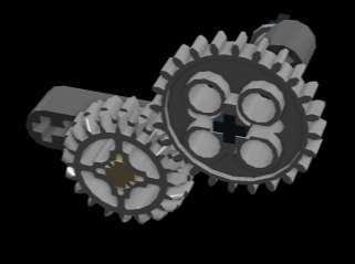
65 Gears: Hands-on parts needed 24z gear 8z gear 3m axle 4m axle 5m axle Double Cross Block Bionicle Eye Half-bushing bushing 65


66 Gears: Building instructions Insert 4M axle into the 24z gear. Insert the gear assembly through the fourth hole in the beam. Install bushing on the axle. Install double cross block on the axle behind the bushing. Insert the 3M axle into the other end of the double cross block. 66


67 Gears: Building instructions Insert the 5M axle into the 8z gear. Insert the gear assembly into the second hole in the beam. Install the half-bushing onto the other side of the 5M axle. Install the orange bionicle eye on the other end. FRONT BACK 67

68 Gear: Testing Turn the crank slowly one rotation and count the number of rotation of the bionicle eye. How many turns did the bionicle eye make? 68


69 Gears: Motion Transfer How can you achieve linear motion? 69
70 Motion Transfer Hands-on activity 70

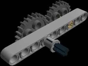
71 Motion Transfer: Building instructions Place 5M axle in 24z gear. Insert gear into fifth hole in an 11M beam. Insert gray non-fraction peg into hole on gear. 71
 second hole on gray peg. Insert gray non-friction peg in last hole of 7M beam.")
72 Motion Transfer: Building instructions Insert gray non-friction peg in last hole on 11M beam. Insert 11M beam (red) second hole on gray peg. Insert gray non-friction peg in last hole of 7M beam. Insert 7M beam (yellow) on gray non-friction pegs on gear and 7M beam (red). 72

73 Motion Transfer: Building instructions Insert bushing on 5M axle on the opposite side of 11M beam. Insert double cross block on 5M axle. Insert second 5M axle into double cross block. 73
74 Motion Transfer: Testing Rotate the handle (5M axle). What happens to the forward (red) 11M beam? 74


75 Linear Motion with a motor Adding a motor to drive linear motion is simple. The 24z gear and drive motor both have three holes. 75

76 Gears: Using worm gears Worm gears can be used to create linear motion too. This Forklift attachment is one example. Rotating the gear causes the forklift arms to travel up and down. Notice that the 8z gear does not rotate. 76


77 Caster : LEGO Steel Ball : Power Joint + = 77


78 Wheels (Tyres), Rims, and Tracks The LEGO Group is one of the world s largest tyre manufacturers : Tyre Low Wide 56 X : Rim Wide 43.2 X 26 with 6 Holes : Track Element, 5X : Sprocket, Ø 40,7 78

79 Simple Wheel Matching Assembly the two wheels on an axle with a bushing in the middle. Align the bushing with the line on a slight slope with the axle at 90 to the line. Let the wheel assembly roll down the slope and watch if the bushing moves off the line. 79


80 Miscellaneous Upper Part For Turntable 28z : Wedge-Belt Wheel Ø : Tyre For Wedge-Belt Wheel :1Bionicle Eye : 2X1X3 Steering Knuckle Arm 80


81 Decorative elements Are just that. Have been used for a number of things Left Panel 3X Right Panel 3X Left Panel 5X Right Panel 3X5 81

82 How many? Take six eight-stud LEGO bricks (2x4) how many ways can they be combined? With the aid of computers, the exact number of combinations has been calculated as 915,103,765! Just so you know, two eight-stud LEGO bricks can be combined in 24 different ways and three eight-stud LEGO bricks in 1,060 ways. 82

83 Presentation available at: 83
FLL Coaches Clinic Chassis and Attachments. Patrick R. Michaud
 FLL Coaches Clinic Chassis and Attachments Patrick R. Michaud pmichaud@pobox.com Erik Jonsson School of Engineering and Computer Science University of Texas at Dallas September 23, 2017 Presentation Outline
the complete parts reference bricks
 the complete parts reference Here s a detailed overview of all the pieces in your LEGO BOOST kit. You can also identify LEGO elements precisely by their LEGO ID, which is printed on the LEGO BOOST test
The Wheels Module The Seats Module Integrate the seats and Wheels modules Ferris Wheel base Build the Gear System...
 Alternate Motorization Kit The Wheels Module... 2 The Seats Module... 3 Integrate the seats and Wheels modules... 4 Ferris Wheel base... 5 Build the Gear System... 7 Ferris Wheel Final Integration!!!...
LEGO 2D Planar Manipulator (with zero offset between Z1 and Z2 axes of rotation)
") LEGO 2D Planar Manipulator (with zero offset between Z1 and Z2 axes of rotation) Uses some parts not found in NXT Mindstorms Kit 9797 e.g. 2 nd Turntable, 1x12 plates, and 15100: Pin-hole Friction Peg.
LEGO 2D Planar Manipulator (with zero offset between Z1 and Z2 axes of rotation) Uses some parts not found in NXT Mindstorms Kit 9797 e.g. 2 nd Turntable, 1x12 plates, and 15100: Pin-hole Friction Peg.
In order to do this project you should review the following concepts:
 Catapult In order to do this project you should review the following concepts: Catapult 18 Rope Lego Band Rubber Band Catapult: Arm Catapult: Arm Catapult: Arm Leave the other end of the rubber band loose
Spare Parts. Contents. Contents Contents
 Spare Parts 2013 Spare Parts Contents Contents Contents LEGO Education StoryStarter 3 LEGO Education WeDo 4 Machines and Mechanisms 5 LEGO MINDSTORMS Education 6-8 TETRIX by Pitsco 9-16 LEGOeducation.us
ORTOP Modular Robot v3.0 Arm Assembly
 Base Plate Assembly Parts Needed: Arm Assembly BAG 1 2 Socket Head Cap Screw, 1-1/4" 2 Socket Head Cap Screw, 1/2" 2 Button Head Cap Screw, 3/8" 6 Nuts 1 Gear Hub Spacer 1 Flat Building Plate 1 Single
This is a motor attachment option in which the motors attach closely to the sides of the NXT.
 6 II. Ways to Attach NXT Motors 1. Simple Side Attachment Model Description: This is a motor attachment option in which the motors attach closely to the sides of the NXT. 7 These are the parts that you
Chassis & Attachments 101. Chassis Overview
 Chassis & Attachments 101 Chassis Overview 2016 1 Introductions Rest rooms location. Food and Drink: Complementary bottled water. Snacks available for purchase from UME FTC teams. Cell phones. Today presentation
Hare and Snail Challenges READY, GO!
 Hare and Snail Challenges READY, GO! Pre-Activity Quiz 1. What are some design considerations to make a fast robot? 2. What are some design considerations to make a slow robot? 2 Pre-Activity Quiz Answers
Model Name: robo. Number of Bricks: Lego Digital Designer
 Model Name: robo Number of Bricks: 197 file:///c:/users/christos/desktop/adsf/building%20instructions%20[robo].html 1/58 Step 1 of 54 file:///c:/users/christos/desktop/adsf/building%20instructions%20[robo].html
Chassis & Attachments 101. Part 1: Chassis Overview
 Chassis & Attachments 101 Part 1: Chassis Overview 2017 1 Introductions Rest rooms location. Food and Drink. Cell phones. Today presentation available at: http://www.roboplex.org/fll 2 What can be used
Team #3691 FLL Technical Manual. Ashburn Robotics NXTreme (Team#3691)
") FLL 2010-11 Team #3691 http://www.ashburnrobotics.com/ TechManual NXTreme 3691 - FLL 2010-11.doc Body Forward Page 1 of 44 TechManual NXTreme 3691 - FLL 2010-11.doc Body Forward Page 2 of 44 Ashburn Robotics
FLL 2010-11 Team #3691 http://www.ashburnrobotics.com/ TechManual NXTreme 3691 - FLL 2010-11.doc Body Forward Page 1 of 44 TechManual NXTreme 3691 - FLL 2010-11.doc Body Forward Page 2 of 44 Ashburn Robotics
FLL Robot Design Workshop
 FLL Robot Design Workshop Tool Design and Mechanism Prepared by Dr. C. H. (Tony) Lin Principal Engineer Tire and Vehicle Mechanics Goodyear Tire & Rubber Company tony_lin@goodyear.com Description Mechanism
Deriving Consistency from LEGOs
 Deriving Consistency from LEGOs What we have learned in 6 years of FLL and 7 years of Lego Robotics by Austin and Travis Schuh 1 2006 Austin and Travis Schuh, all rights reserved Objectives Basic Building
introduction what do I need to use this book? playing without a computer the EV3 software whom is this book for?
 The idea for this book was born in 2012 during a sandstorm in Saudi Arabia. I was locked in my hotel room waiting for the weather to improve and listening to Paul Dukas s symphonic poem The Sorcerer s
Installation Tutorial
 Installation Tutorial 1. Remove the finger parts, if the film, tear off the surface of the film, the number of parts were 1 4 4 5 5 2. First assemble the big finger parts, use M2X3 screws, M2X6 copper
MM540 Installation Instructions IMPORTANT SAFETY INSTRUCTIONS - SAVE THESE INSTRUCTIONS
 MM50 Installation Instructions IMPORTANT SAFETY INSTRUCTIONS - SAVE THESE INSTRUCTIONS Please read this entire manual before you begin. Do not unpack any contents until you verify all requirements on PAGE.
What is power? Work is done when an object moves in the same direction in which the force is exerted. What is work?
 What is Work? Question What is work? Answer Work is done when an object moves in the same direction in which the force is exerted. How can you calculate work? Work = Force X Distance What is power? Power
Obtained from Omarshauntedtrail.com
 DaveintheGrave's Halloween Props Animated Crawling Skeleton Build a life-size skeleton torso that realistically crawls across the lawn one arm at a time. 1. Motor Base and Linkage Assembly BASE - I used
BY ALIEN TECHNOLOGIES CORP
 BY ALIEN TECHNOLOGIES CORP Assembly Instructions TopLift Pros YOU MAY ALSO REVIEW OUR ASSEMBLY VIDEO, PLAY AND PAUSE AT YOUR CONVENIENCE. JUST VISIT US AT WWW.TOPLIFTPROS.COM AND GO TO Customer Support
LEGO Mindstorms Class: Lesson 1
 LEGO Mindstorms Class: Lesson 1 Some Important LEGO Mindstorm Parts Brick Ultrasonic Sensor Light Sensor Touch Sensor Color Sensor Motor Gears Axle Straight Beam Angled Beam Cable 1 The NXT-G Programming
Removing and Replacing the Y-truck
 Service Documentation Removing and Replacing the Y-truck To remove and replace the Y-truck you will need the following tools: 4mm Allen wrench 12mm stamped flat wrench #2 Phillips screwdriver (magnetic
MM750 Installation Instructions
 MM750 Installation Instructions IMPORTANT SAFETY INSTRUCTIONS - SAVE THESE INSTRUCTIONS Please read this entire manual before you begin. Do not unpack any contents until you verify all requirements on
9. Weld a cross brace between the H frame and the A frame on each side. 10. Remove all the bracing and blocks, now you have I frame to work off.
 Foam target butts 1. Determine what butts you wish to install we used 4 different types not the best idea as we had to make 2 different size frames 2. Find the wheels you wish to use I prefer large wheels
C-180 Builder s Manual
 C-180 Builder s Manual. May 20, 2002 Last revised July 11, 2002 Copyright! 2002 Douglas Binder, Mountain Models www.mountainmodels.com sales@mountainmodels.com (719) 630-3186 1 Required Equipment! Xacto
Electric Skein Winder
 Electric Skein Winder Assembly and Use Package Contents 1 - Triangular Body (w/ motor) 1 - Cross Arm 1 - Left Foot (w/ yarn guide) 1 - Right Foot 1 - Adjustable Finger (w/ yarn clip) 3 - Adjustable Fingers
Gardman Lean-to Greenhouse Assembly Instructions
 Page 1 Gardman Lean-to Greenhouse Assembly Instructions Our Help Line provides support and advice to customers of Summer Garden Buildings after ordering. For advice before you buy you can phone us free
installation guide
 JANUS INTERNATIONAL 1 866 562 2580 w w w. j a n u s i n t l. c o m 2000 2500 3000 installation guide RIGHT DRIVE END SHOWN LH OPPOSITE LEFT TENSION END SHOWN RH OPPOSITE PUSH-UP OPERATION 2000 2500 3000
Number Wheeler P/N Description Set Rex P/N Notes Base 1 J Support, Right 1 J Support, Left 1 J Nut (M8)
") 1 603500 Base 1 J001 2 603501 Support, Right 1 J002 3 603502 Support, Left 1 J003 4 600328 Nut (M8) 4 5 600130 Spring Washer (8mm) 4 6 600344 Roll Pin (M6x30) 4 7 600129 Socket Hd Cap Screw (M8x25) 4 8
1 603500 Base 1 J001 2 603501 Support, Right 1 J002 3 603502 Support, Left 1 J003 4 600328 Nut (M8) 4 5 600130 Spring Washer (8mm) 4 6 600344 Roll Pin (M6x30) 4 7 600129 Socket Hd Cap Screw (M8x25) 4 8
MM340 Installation Instructions IMPORTANT SAFETY INSTRUCTIONS - SAVE THESE INSTRUCTIONS
 MM30 Installation Instructions IMPORTANT SAFETY INSTRUCTIONS - SAVE THESE INSTRUCTIONS Please read this entire manual before you begin. Do not unpack any contents until you verify all requirements on PAGE.
Efficiency. Efficiency is a measure of how much of the work put into a machine is changed into useful output work by the machine.
 Efficiency Efficiency is a measure of how much of the work put into a machine is changed into useful output work by the machine. A machine with high efficiency produces less heat from friction so more
re3d Assembling Gigabot: "Flatpack"
 re3d Assembling Gigabot: "Flatpack" Your Gigabot was assembled, calibrated, tested, and taken apart for shipping purposes. All you need to do is reassemble it, and you're ready to go! Written By: Chris
Technical analysis and diagramming exercises
 Technical analysis and diagramming exercises 1 st year of the second cycle Name: Corrected version June 2010 By a team made up of: Madame Isabelle Lafrance, pedagogical counsellor at the commission scolaire
HD installation guide
 JANUS INTERNATIONAL 1 866 562 2580 www.janusintl.c o m 1950 1950HD installation guide RIGHT DRIVE END SHOWN LH OPPOSITE LEFT TENSION END SHOWN RH OPPOSITE PUSH-UP OPERATION 1950 1950HD SHOWN A rolling
Mobile Weapons Storage System Specifications
 Mobile Weapons Storage System Specifications Whatever your weapon storage needs, Hi-Density s customized Weapons Storage System will be designed to fit your unique specifications. We recognize that security
FIRST TEAM SPORTS, INC.
 FIRST TEAM SPORTS, INC. INVADER EZ-CRANK PORTABLE BASKETBALL GOAL ASSEMBLY INSTRUCTIONS Revised - 08/04/10 BILL OF MATERIALS (1) BASE TANK (1) BACKBOARD MOUNT (2) 5/16 X ¾ HEX BOLT (1) LOWER POST (2) SPRING
Final Review Powerpoint
 Final Review Powerpoint Simple Machines- A device that makes work easier, faster, or changes the direction of force using few or no moving parts Rube Goldberg- a complex machine that does a simple task
RC4WD Diablo V2 Instruction Manual
 Version 1.1 RC4WD Diablo V2 Instruction Manual Thank you for your purchase. Welcome to the RC4WD family. This kit is a combination of many specially engineered and manufactured parts. Enjoy your build.
E N G L I S H GARDEN SHED. Assembly Instructions. Suitable for Models WITH VARYING DEPTHS
 GARDEN SHED Assembly Instructions Suitable for Models 6' Wide 8' Wide 0' Wide WITH VARYING DEPTHS GI0003 November 0 INSTALLATION ADVICE It's Not That Difficult! The construction of your shed isn't as complicated
Castle Frame Assembly Table AT-8. Diagnostics Manual. Castle, Inc. Petaluma, CA
 Castle Frame Assembly Table AT-8 Diagnostics Manual Castle, Inc. Petaluma, CA 800-282-8338 Solutions Index Adjusting the Tabletop.. 8.01 Adjusting the Fence... 8.02 Aligning the Arm... 8.10 Adjusting Bracket..
Installation and Assembly - Universal Articulating Swivel Double-Arm for 42" - 60" Plasma Screens
 Installation and Assembly - Universal Articulating Swivel Double-Arm for 42" - 60" Plasma Screens Models: PLAV 70-UNL, PLAV 70-UNL-S PLAV 70-UNLP, PLAV 70-UNLP-S R This product is UL Listed. It must be
Parts Manual. Model: / WHF / WHF5219 MANUAL NO REV. 01 (09/15/04)
") Parts Manual Model: 685 / WHF4817 6853 / WHF51 MANUAL NO. 531586 REV. 01 (0//04) MODEL NUMBER SERIAL NUMBER DATE PURCHASED DEALER ADDRESS NOTES: 004 Husqvarna. All rights reserved. Beatrice, NE. Printed
Parts Manual Model: 685 / WHF4817 6853 / WHF51 MANUAL NO. 531586 REV. 01 (0//04) MODEL NUMBER SERIAL NUMBER DATE PURCHASED DEALER ADDRESS NOTES: 004 Husqvarna. All rights reserved. Beatrice, NE. Printed
Brother Industries, Ltd. Nagoya, Japan
 4. 2001. This service manual has been compiled for explaining repair procedures of the MODEL XL-6562, XL6452, XR- 46. This was produced based on up-to-date product specifications at the time of issue,
OPERATIONS MANUAL. Port-O-Slitter
 Tapco Products Company The World Leader in Specialty Tools for the Professional Port-O-Slitter OPERATIONS MANUAL General instructions, set up, accessories and guide to using your portable precision slitting,
# in 1 Metal Worker Auxiliary Operating Instructions
 340 Snyder Avenue, Berkeley Heights, NJ 07922 www.micromark.com MMTechService@micromark.com Tech Support: 908-464-1094, weekdays, 1pm to 5 pm ET #86556 3 in 1 Metal Worker Auxiliary Operating Instructions
A Portable, Human-Powered Lathe Designed and Built by Scott Lewis Illustrations by David Heim
 Tailstock Toolrest and banjo Drive belt guard Headstock post Headstock spindle Page 1 Metric dimensions Tailstock post Drive belt tensioner Drive belt and flywheel Chair Bicycle pedals, sprockets, and
Worksheet Answer Key: Tree Measurer Projects > Tree Measurer
 Worksheet Answer Key: Tree Measurer Projects > Tree Measurer Maroon = exact answers Magenta = sample answers Construct: Test Questions: Caliper Reading Reading #1 Reading #2 1492 1236 1. Subtract to find
DYNATRAC BALL JOINT REBUILD INSTRUCTIONS V4.0
 DYNATRAC PRODUCTS 2007-2016 4X4 JEEP JK HEAVY DUTY BALL JOINT JP44-2X3050-C DYNATRAC BALL JOINT REBUILD INSTRUCTIONS V4.0 WARNING: Improper use or installation of this product can cause major failures
Lab book. Exploring Robotics (CORC3303)
") Lab book Exploring Robotics (CORC3303) Dept of Computer and Information Science Brooklyn College of the City University of New York updated: Fall 2011 / Professor Elizabeth Sklar UNIT A Lab, part 1 : Robot
Lab book Exploring Robotics (CORC3303) Dept of Computer and Information Science Brooklyn College of the City University of New York updated: Fall 2011 / Professor Elizabeth Sklar UNIT A Lab, part 1 : Robot
3D PRINTER. Pack 11. Anything you can imagine, you can make! 3D technology is now available for you at home! BUILD YOUR OWN
 BUILD YOUR OWN Pack 11 Anything you can imagine, you can make! 3D PRINTER Compatible with Windows 7 & 8 Mac OS X 3D technology is now available for you at home! BUILD YOUR OWN 3D PRINTER CONTENTS PACK
aluminium profile system
 aluminium profile system 63 AME System aluminium profiles overview series profiles introduction 80x80 x80 x80/180 x Aluminium profiles are provided with longitudinal grooves which can be used in conjunction
PROSTEER BALL JOINT REBUILD INSTRUCTIONS V1.0
 DYNATRAC PRODUCTS 2003-2010 4X4 DODGE 2500/3500 HEAVY DUTY BALL JOINT PROSTEER BALL JOINT REBUILD INSTRUCTIONS V1.0 WARNING: Improper use or installation of this product can cause major failures that could
PoeBot Building Instructions CCISD. Upper Gripper. Lower Gripper/ Spatula. PoeBot Instructions PLTW. Clear Creek ISD
 Upper Gripper Lower Gripper/ Spatula PoeBot Instructions PLTW Clear Creek ISD 1. Chasis Construction (Split Group with half starting Step 1 and half starting Step 13.) Note: These flat bearings are offset
An Introduction to Programming using the NXT Robot:
 An Introduction to Programming using the NXT Robot: exploring the LEGO MINDSTORMS Common palette. Student Workbook for independent learners and small groups The following tasks have been completed by:
Insolroll Clutch Operated Shades Installation Instructions Installation Instructions
 All clutch operated shades are shipped fully assembled and ready for installation. Mounting screws are not provided. Screws for chain guide installation to meet the child safety standards are provided.
FACTORY CAT TOMCAT CORPORATION
 FACTORY CAT RPS TOMCAT CORPORATION Artificial Turf and Carpet Sweeping Install Kit #349-641 & #349-642 1. Detach batteries so that there is no power running through the machine before starting. 2. Start
Assembly Instructions for Model: VMDD26
 Assembly Instructions for Model: VM26 Thank you for choosing a Sanus Systems Vision Mount wall mount. The VM26 is designed to mount up to 63 lat panel televisions weighing up to 175 lb. to a vertical wall.
JARVIS. Model BR-3 Blade Reconditioner ... EQUIPMENT TABLE OF
 - Model BR-3 Blade Reconditioner EQUIPMENT SELECTION.......... Ordering No. TABLE OF CONTENTS............................ Page Model BR-3 (100 mm Blade) 115V/60Hz............ 4011003 220V/50Hz............
Installation and Assembly: In-wall Mount for 32" to 71" Flat Panel Screens
 Installation and Assembly: In-wall Mount for 32" to 71" Flat Panel Screens Model# IM760P, IM760P-S IM760PU, IM760PU-S Screen size range 32" to 71" (81 to 180 cm) 32" to 60" (81 to 152 cm) IM760P IM760P-S
Wheelchair Attachment
 Wheelchair Attachment Set-Up Guide and Registration Pages 1-4: Steps to Set-Up your FreeWheel Page 5: Page 6: Page 7: Page 5: Page 9: Back: Clamp Plate Footrests and TiLite Angle-Adjustable Footrest Modifications
Mold #328. Roller Bot. Nail Bot. You will need the following. pieces from mold #328 for this robot. mold #328 for this robot.
 Nail Bot mold #328 for this Mold #328 Roller Bot mold #328 for this Stand the piece up and glue the tanks onto the back of the piece. Be sure to center the tanks. Lay these two pieces down on a flat surface
2018 First Responders 4-H Robotics Challenge Page 1
 2018 First Responders 4-H Robotics Challenge Page 1 Contents 2018 First Responders 4-H Robotics Challenge... 3 1 Teams... 3 2 The Game... 3 2.1 Competition kit... 3 2.2 Field Mat... 3 2.3 Playing Field...
TRAILMATE METEOR ASSEMBLY MANUAL
 TRAILMATE METEOR ASSEMBLY MANUAL The Trailmate Meteor recumbent has been designed for easy assembly. This means more time to enjoy the smooth ride with single speed, 3 speed coaster brake and 21 speed
Screw. Introduction This Rokenbok STEM-Maker lesson will use the following steps to learn about the screw. Learning Objectives. Resources.
 Screw Progression: Applications in Design & Engineering - Section 6 Curriculum Packet v2.0 Introduction This Rokenbok STEM-Maker lesson will use the following steps to learn about the screw. 1. Learn 2.
Installation Instructions
 by Plato Woodwork Installation Instructions Plato Woodwork, Inc. 200 Third Street SW P.O. Box 98 Plato, MN 55370 www.platowoodwork.com 800.328.5924 SECTION GUIDE GETTING STARTED PAGE # Installation Methods...
MantelMount. TM1A Installation Instructions IMPORTANT SAFETY INSTRUCTIONS - SAVE THESE INSTRUCTIONS
 MantelMount TMA Installation Instructions IMPORTANT SAFETY INSTRUCTIONS - SAVE THESE INSTRUCTIONS TM Thank you for choosing the MantelMount television wall mount. Please read this entire manual before
40 & 50 Foot PS-1 Box Car Assembly Instructions
 40 & 50 Foot PS-1 Box Car Instructions Push the #2100 coupler/stirrup assembly onto the ends of the metal floor. Slide them into the slots and slightly lift the ends (wings), then press firmly on the front
FORWARD FUSELAGE SIDES & REAR TOP SKINS
 FORWARD FUSELAGE SIDES & REAR TOP SKINS WORK REPORT Step No. Check Parts / Tools Qty Preparations. 1 [ ] 6F5-3 Upper Front Longerons 2 2 [ ] 6F5-5 Heel Support 1 3 [ ] 6F5-2 Front Floor Skin 1 3 [ ] Firewall
INS A KSCR INSTALLATION INSTRUCTIONS STANDARD PROCEDURE. 1. Unpacking the KSCR Splicing the KSCR (If Required)...
...") INS-88.500-0A KSCR INSTALLATION INSTRUCTIONS STANDARD PROCEDURE 1. Unpacking the KSCR... 2 2. Splicing the KSCR (If Required)... 4 3. Assemble Curb and Rail Corners... 5 4. Install Cross Bracing (If Required)...
INS-88.500-0A KSCR INSTALLATION INSTRUCTIONS STANDARD PROCEDURE 1. Unpacking the KSCR... 2 2. Splicing the KSCR (If Required)... 4 3. Assemble Curb and Rail Corners... 5 4. Install Cross Bracing (If Required)...
Where C= circumference, π = 3.14, and D = diameter EV3 Distance. Developed by Joanna M. Skluzacek Wisconsin 4-H 2016 Page 1
 Instructor Guide Title: Distance the robot will travel based on wheel size Introduction Calculating the distance the robot will travel for each of the duration variables (rotations, degrees, seconds) can
18600 Angular Momentum
 18600 Angular Momentum Experiment 1 - Collisions Involving Rotation Setup: Place the kit contents on a laboratory bench or table. Refer to Figure 1, Section A. Tip the angular momentum apparatus base on
It is highly recommended that you use a thread lock compound such as Loctite brand on all threads to keep them from vibrating loose.
 Installation instructions for FC12 Forward Controls for Kawasaki Vulcan 750 It is highly recommended that you use a thread lock compound such as Loctite brand on all threads to keep them from vibrating
Desktop Trebuchet Kit Assembly Instructions
 Desktop Trebuchet Kit Assembly Instructions Contents of package (drawings are not to scale for clarity, parts that have duplicates are indicated with total number of that part to be found, example: 2X
SatNOGS. SatNOGS Rotator v3 Mechanical Assembly. This is the assembly guide for the third version of the SatNOGS Rotator.
 SatNOGS SatNOGS Rotator v3 Mechanical Assembly This is the assembly guide for the third version of the SatNOGS Rotator. Written By: Pierros Papadeas 2017 satnogs.dozuki.com Page 1 of 19 INTRODUCTION Notes:
Installation Instructions
 CHEVY / GMC 16K Industry Standard Rail Custom Mounting Kit #2730 Gross Trailer Weight (Maximum)...16,000 lbs. Vertical Load Weight (Max. Pin Weight)...4,000 lbs. SYSTEM TOW CAPACITY Please note, in order
INSTRUCTION BOOKLET #C20
 INSTRUCTION BOOKLET #C0 WARNING! ALL MURPHY/WALLBED SYSTEMS CONTAIN STORED ENERGY. FAILURE TO USE AND FOLLOW THESE INSTRUCTIONS DURING THE INSTALLATION PROCESS COULD RESULT IN SEVERE PERSONAL INJURY TO
Installation Instructions
 FORD 20K Industry Standard Rail Custom Mounting Kit #2738 Gross Trailer Weight (Maximum)...20,000 lbs. Vertical Load Weight (Max. Pin Weight)...5,000 lbs. SYSTEM TOW CAPACITY Please note, in order to determine
Installation Instructions
 CHEVY / GMC 20K Industry Standard Rail Custom Mounting Kit #2724 Gross Trailer Weight (Maximum)...20,000 lbs. Vertical Load Weight (Max. Pin Weight)...5,000 lbs. SYSTEM TOW CAPACITY Please note, in order
LEGENDS RETRACTABLE DOOR SCREENS
 LEGENDS RETRACTABLE DOOR SCREENS MAGNETIC LATCHING DESIGN SYSTEM 42 I N S T A L L A T I O N I N S T R U C T I O N S 1 MOUNTING OPTIONS Recess : Mount the Screen Cassette using Recess Mounting Clips Recess
Installation and Assembly - Universal Articulating Swivel Double-Arm for 42" - 60" Plasma Screens
 Installation and Assembly - Universal Articulating Swivel Double-Arm for 42" - 60" Plasma Screens Models: PLAV 70-UNL, PLAV 70-UNL-S PLAV 70-UNLP, PLAV 70-UNLP-S R This product is UL Listed. It must be
Service Manual for XLE/XLT Series Laser Engravers
 Service Manual for XLE/XLT Series Laser Engravers Table of Contents Maintenance...1 Beam alignment...3 Auto focus alignment...8 Bridge alignment...10 Electronics panel replacement...11 X motor change...12
Installation Instructions for FC2 & FC15 Forward Controls for the Super Magna
 Installation Instructions for FC2 & FC15 Forward Controls for the Super Magna It is highly recommended that you use a thread lock compound such as Loctite brand on all threads to keep them from vibrating
Robotics using Lego Mindstorms EV3 (Intermediate)
") Robotics using Lego Mindstorms EV3 (Intermediate) Facebook.com/roboticsgateway @roboticsgateway Robotics using EV3 Are we ready to go Roboticists? Does each group have at least one laptop? Do you have
Robotics using Lego Mindstorms EV3 (Intermediate) Facebook.com/roboticsgateway @roboticsgateway Robotics using EV3 Are we ready to go Roboticists? Does each group have at least one laptop? Do you have
2015 Maryland State 4-H LEGO Robotic Challenge
 Trash Talk Utilizing Trash to Power the World 2015 Maryland State 4-H LEGO Robotic Challenge Through Trash Talk, 4-H members involved in robotics will create LEGO robots that complete tasks related to
400GTO Lubrication Guide
 400GTO Lubrication Guide Lubrication Guidelines for the following equatorial mounting: 400GTO Servo with GTOCP2 or CP3 Controller For other 400 models please review other postings as they become available.
PREVIEW COPY. Table of Contents. Lesson One Using the Dividing Head...3. Lesson Two Dividing Head Setup Lesson Three Milling Spur Gears...
 Table of Contents Lesson One Using the Dividing Head...3 Lesson Two Dividing Head Setup...19 Lesson Three Milling Spur Gears...33 Lesson Four Helical Milling...49 Lesson Five Milling Cams...65 Copyright
Ruby 0-4-0T Kit Assembly Instructions
 Ruby 0-4-0T Kit Assembly Instructions Ruby Parts List PART NO.& NAME QTY PART NO.& NAME QTY SHEET 1 1 Frame 2 2 Bracket 4 3 M2 x 4 Hex Head Screw 25 4 Wheelset (without eccentrics) 1 5 Wheelset (with eccentrics)
Installation Instructions Universal Crossmember Kit - 60 Track Width BEFORE Measure Twice, Weld Once! II
 Installation Instructions Universal Crossmember Kit - 60 Track Width Please read these instructions completely BEFORE starting your installation. Remember the basic rule for a successful installation:
Greenhouse Assembly Instructions
 Greenhouse Assembly Instructions Our Help Line provides support and advice to customers of Summer Garden Buildings after ordering. For advice before you buy you can phone us free 7 days a week on 0800
The Phoenix. Professional Quilting Frame. Copyright January 1, 2016 Jim M. Bagley, GraceWood, Inc (Reproduction Prohibited) Version 2.
 Version 2.") The Phoenix Professional Quilting Frame Copyright January 1, 2016 Jim M. Bagley, GraceWood, Inc (Reproduction Prohibited) Version 2.1 1 The Phoenix Professional Quilting Frame Parts List Box 1...3 Box
The Phoenix Professional Quilting Frame Copyright January 1, 2016 Jim M. Bagley, GraceWood, Inc (Reproduction Prohibited) Version 2.1 1 The Phoenix Professional Quilting Frame Parts List Box 1...3 Box
Assembly Instructions. Beta Prusa DualX 3D Printer
 Assembly Instructions Beta Prusa DualX 3D Printer Version 2.6 Date Page 1 / 72 General data about the assembly instructions for an incomplete machine according to appendix VI of the EG machinery directive
Parts Manual. English
 Parts Manual WHF4817 / 966947005 WHF3617 / 966947008 Please read the operator s manual carefully and make sure you understand the instructions before using the machine. English 2009 HTC. All rights reserved.
ELECTRIC RACER BASIC BUILD
 Page 1 Name: Set: Date: This guide will take you through the process of creating a basic electric racer. After you finish this build, you should be able to experiment, design and engineer your own racer.
Catapult Engineering
 With support from Oxfordshire County Council, Science Oxford is pleased to present; Catapult Engineering The Physics of Siege Weapons STEM Club Resource Pack Introduction: Catapult engineering involves
POP PLUS / SPIDER SET-UP INSTRUCTIONS
 POP PLUS / SPIDER SET-UP INSTRUCTIONS 1 Place system frame on floor with screws indicating top. Expand upwards & outwards and secure frame connectors. Pop-Up display systems are made to be set-up and taken
PORTABLE ADJUSTABLE BASKETBALL SYSTEM
 Instruction Manual PORTABLE ADJUSTABLE BASKETBALL SYSTEM P A R T S L I S T 5 1/2 and 8 safe play clearance Item Qty Description Item Qty Description A 1 Portable Base Assembly M 4 1/2 Lock Nut B 2 Front
INSTALLATION OF THE TRACK FOR THE STRAIGHT SIDE STEEL LADDER
 ASSEMBLY OF THE 7180 STRAIGHT SIDE STEEL LADDER TOOLS REQUIRED FOR ASSEMBLY SAFETY GLASSES (2) 1 / 2 WRENCHES OR SOCKETS STEP LADDER OF APPROPRIATE HEIGHT (2) 7 / 16" WRENCHES OR SOCKETS HACKSAW FLAT HEAD
LB. POLY PRO DROP SPREADER
 owners manual Model No. -02882 17 LB. POLY PRO DROP SPREADER CAUTION: Read Rules for Safe Operation and Instructions Carefully Safety Assembly Operation Maintenance Parts the fastest way to purchase parts
Removing Right-Side. Components. Right-Side. Components. Click Here to Go Back AT THIS POINT
 Click Here to Go Back NOTE: There is an oil passage beneath the driven gear/drive gear assembly. This passage should be plugged prior to removing the driven gear and drive gear. Failure to do so could