3DOF Leg Kit Assembly Guide VERSION 1.0
|
|
|
- Buck Randall
- 5 years ago
- Views:
Transcription
1 3DOF Leg Kit Assembly Guide VERSION 1.0
2 WARRANTY CrustCrawler warrants its products against defects in materials and workmanship for a period of 30 days. If you discover a defect, CrustCrawler will, at its option, repair, replace, or refund the purchase price. Simply call for a Return Merchandise Authorization (RMA) number, write the number on the outside of the box and send it back to CrustCrawler. Please include your name, telephone number, shipping address, and a description of the problem. We will return your product, or its replacement, using the same shipping method used to ship the product to CrustCrawler. 14-DAY MONEY BACK GUARANTEE If, within 14 days of having received your product, you find that it does not suit your needs, you may return it for a full refund. CrustCrawler will refund the purchase price of the product, excluding shipping / handling costs. This does not apply if the product has been altered or damaged. Please refer to our web site for the latest warranty information. COPYRIGHTS AND TRADEMARKS This documentation is copyright 2004 by CrustCrawler, Inc. BASIC Stamp is a registered trademark of Parallax, Inc. If you decided to use the name BASIC Stamp on your web page or in printed material, you must state that "BASIC Stamp is a registered trademark of Parallax, Inc." Other brand and product names are trademarks or registered trademarks of their respective holders. DISCLAIMER OF LIABILITY CrustCrawler, Inc. is not responsible for special, incidental, or consequential damages resulting from any breach of warranty, or under any legal theory, including lost profits, downtime, goodwill, damage to or replacement of equipment or property, and any costs or recovering, reprogramming, or reproducing any data stored in or used with CrustCrawler products. CrustCrawler is also not responsible for any personal damage, including that to life and health, resulting from use of any of our products. You take full responsibility for your BASIC Stamp and robotic application, no matter how life-threatening it may be. INTERNET ACCESS We maintain internet systems for your use. These may be used to obtain software, communicate with members of CrustCrawler, and communicate with other customers. Access information is shown below: Support@CrustCrawler.com Web:
3 REQUIRED TOOLS The following tools will be required to build your Hexcrawler HDATS: Phillips screwdriver Drill 1/8 drill bit Small adjustable crescent wrench or socket set Wire cutters A small amount of white grease or equivalent 3DOF INVENTORY The 3DOF kit contains the following components: Wiring: Servo Wire Extensions (1) 12 Aluminum Parts: (1) Servo Hinge Bracket (1) Servo holder (1) Front leg brace (1) Back leg brace (1) Front foot (1) Back foot (1) Servo pivot brace Nuts, Bolts, Washers Screws & Spacers (2) #2-5/16 screws (4) #4 1/4 screws (4) #4 5/16 screws (6) #4 nuts (2) #4 lock nuts (6) #4 lock washers (2) #4 washers (6) #6 3/8 screws (6) #6 nuts (6) #6 lock washers (1) #6 1/2 screw (2) #6 washers (1) #6 lock nuts (1) #6 nut (5) ¼ SAE flat washers (1) # screw (1) #8 Lock nut (2) #8 washers (1) #8 - ½ nylon spacer (1) #8 ¼ nylon spacer (1) Mounting kit
4 Miscellaneous (1) 3DOF leg construction manual (6) Cable Ties (1) Rubber Foot Bumper (2) Tie rod coupler (2) Brass balls (2) #4 hex screws (1) 4/40 threaded rod
5 SERVO SELECTION AND CONSIDERATIONS FOR THE 3DOF LEG KIT Several factors have to be considered when selecting the servos for your 3DOF leg kit: Servo selection is critical for optimum performance of your 3DOF legs. The higher the torque rating, the higher the performance that can be obtained. The overall weight of your robot. The heavier the robot, the higher the torque that is required for the legs to perform properly. Servo size - Any standard size servo (1.6 L X.80 W X 1.5 H) will fit the 3DOF kit. At CrustCrawler we use HiTec servos as they are the best for robotic applications. Hitec servos have karbonite, metal gear and titanium geared servos which make them ultra tough for demanding robotic applications. The list below displays the part number and the torque rating for the Hitec servos that are compatible with the 3DOF leg kit: HiTec Analog Servos HS-475HB (61 in. oz.) HS-635BB (83 in. oz.) HS-625MG (93 in. oz.) HS-645MG (133 in. oz.) HS-925MG (103 in. oz.) HS-945MG (153 in. oz.) HiTec Karbonite Gear Digital Servos HS-6635HB (83 in. oz.) HS-6965HB (111 in. oz.) HS-6975HB (144 in. oz.) HS-6985HB (172 in. oz.) HiTec Titanium Gear Digital Servos HSC-5996TG (111 in. oz.) HSC-5997TG (180 in. oz.) HSC-5998TG (250 in. oz.) HSC-5955TG (333 in. oz.) HSC-5995TG Robot (250 in. oz.)

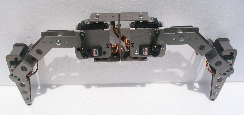
6 This construction guide uses Hitec HS-645MG (133 oz. in.) and HS-475HB (61 oz. in.) servos as an example. Use Figure A below as a guide for servo placement as it relates to its torque value for each of the 3DOF leg joints. At CrustCrawler, we have tested the performance of the legs based on servo selection and their related torque value. Always use at least the minimum torque value specified below or more to obtain the optimum performance from the 3DOF leg design. Be sure to adjust your legs using the (4) fulcrum points if you find that your not obtaining enough torque from the vertical lift servo. Horizontal Servo 133+ oz. in Foot Servo 61+ oz. in Vertical Servo 61+ oz. in Figure A Servo Selection and Placement

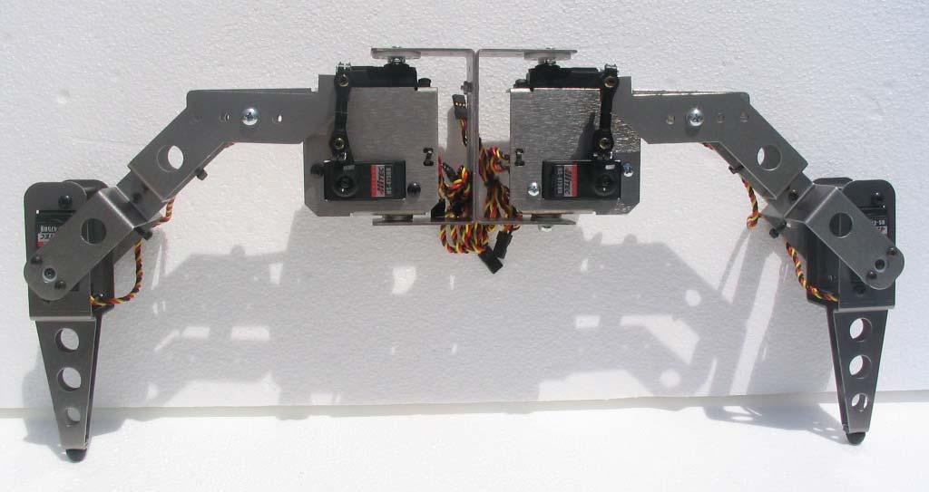
7 Adjustable Fulcrum Points There are (4) adjustable fulcrum points built into the 3DOF leg kit. Move the fulcrum point based on the weight and requirements of your robotic project. Use the figure B as a guide when selecting the fulcrum point of the legs for your project. Maximum leg lift least amount of torque Minimum leg lift most amount of torque

8 PREPARING THE SERVOS Remove the aluminum body parts from their protective bags and lay them loosely in their respective groups on your work surface. Remove the riser tabs from both sides of your servos as shown in figure. The removal of this plastic riser will allow the servo to sit flush against the 3DOF leg hardware later in the construction process. Place these servos to the side of your work area. Figure 1 - Servo Tab Removal


9 Leg Configurations Prior to the construction of your leg kit, determine how the legs are going to mount to your robot body. The servo hinge bracket was designed with slots and holes on all sides to accommodate multiple mounting configurations. Use figures 2A, 2B and 2C as a guide for determining the mounting configuration of your legs kits. Figure 2a Top/bottom deck mount bolts to and upper / lower deck of your robot Figure 2b Side mount bolts to the side of your robot Figure 2c Servo hinge bracket mount - connect this assembly to your robots upper and/ or lower decks
10

 #4 5/16 screws and lock nuts, install the servo horn to the servo hinge bracket as shown in figure 3 and figure 4.")
11 Assembling the Servo Hinge Bracket 1. Using a 1/8 drill bit, drill out the hole of the round servo horn from the servo as shown in figure 2. Tip: Drill the holes with the servo arm still mounted on the servo. After completing the holes, remove the round servo arm and temporarily place the servo screw back onto the servo. Figure 2 - Servo Arm Modification 2. Using (2) #4 5/16 screws and lock nuts, install the servo horn to the servo hinge bracket as shown in figure 3 and figure 4. Ensure that the servo horns center hole is centered in the servo hinge bracket hole before tightening the lock nuts. Figure 3 - Servo Horn Installation


12 Figure 4 - Servo Horn Installation 3. Grease the bottom of the pem spacer as shown in figure 5. Figure 5 Greasing the pem spacer

13 4. Install (2) 1/4 SAE flat washers to the pem spacer as shown in figure 6. The flat sides of the washers should be mounted flush with each other. Grease the top of the pem spacer and place the assembly to the side of your work area. Figure 6 Washer Grease Application To make leg assembly easier, bolt the servo hinge bracket to your robot assembly before going to the next step. 5. Using (2) #6-3/8 screws, lock washers and nuts, install the HiTec HS-645MG servo to the top of the 2 tabs on the servo holder with the servo oriented as shown in figure 7.


14 Figure 7 - Horizontal Servo Installation 6. Install the servo holder onto the pem spacer and the round servo arm of the servo hinge bracket as shown in figure 8. Ensure that the servo can rotate 90 degrees in either direction from a centered position before installing the servo screw as shown in figure 9. Figure 8 Servo Holder Installation
 ¼ SAE flat washer (flat side up) onto the pem")
15 90 Degrees 90 Degrees Figure 9 7. Place (1) ¼ SAE flat washer (flat side up) onto the pem spacer as shown in figure 10.

16 ¼ SAE Flat Washer Figure 10 - Washer Installation


17 8. Install (1) #6-1/2 screw, (2) washers and a lock nut as shown in figures 11 and 12. #6 Flat Washer Figure 11 #6 ½ Screw #6 Flat Washer #6 Lock Nut Figure 12

 tie wrap to secure the servo wires to the servo holder.")
18 9. Using (2) #6-3/8 screws, lock washers and nuts, install the vertical, leg lift servo to the servo holder as shown in figure 13. Ensure that the servo is positioned as shown in figure 13. Use (1) tie wrap to secure the servo wires to the servo holder. Tie Wrap Figure 13 - Vertical Servo Installation Front View Figure 13B 10. Repeat steps 1-9 for each leg in your kit

 ¼ SAE flat washers (flat side towards the back leg) onto the pem spacer and")
19 Leg Assembly 11. Apply a small amount of grease to the pem spacer on the back leg as shown in figure 14. Figure 14 Grease Application 12. Install (2) ¼ SAE flat washers (flat side towards the back leg) onto the pem spacer and apply a small amount of white grease to the top of the second washer as shown in figure 15. Figure 15 Washer Installation and Grease Application

 #6 1/2 screw, (2) washers and (1) lock nut, attach the servo pivot brace and foot assembly from figure 16 to the back leg as shown in figure 17 and 17b.")
20 13. Using (2) #4 5/16 screws, washers, lock washers and nuts, install the back foot to the servo pivot brace as shown in figure 16. Ensure that the large, pem spacer hole of the servo brace is aligned with the pem spacer hole of the back foot before tightening the #4 screws. Pem Spacer Hole Servo Pivot Brace Back Foot Figure Using (1) #6 1/2 screw, (2) washers and (1) lock nut, attach the servo pivot brace and foot assembly from figure 16 to the back leg as shown in figure 17 and 17b. Do not tighten the lock nut completely! Tighten the lock nut just enough so the back leg can swing freely with little resistance. #6 ½ Screw #6 Washer Figure 17

21 #6 Lock Nut #6 Washer Figure 17b

 #6 3/8 screws, lock washers and nuts, install the front foot to")
22 15. Place (1) HiTec 475 HB servo to the top of the servo pivot brace with the servo spindle oriented toward the bottom of the foot as shown in figure 18. Figure Using (2) #6 3/8 screws, lock washers and nuts, install the front foot to the servo as shown in figure 19 and 19b. #6 3/8 Screw Figure 19

23 #6 Lock Washer #6 Nut Figure 19b


24 17. Figure 19c depicts the leg assembly completed to this point. Figure 19c 18. Using (1) #6 nut, and lock washer, install the rubber foot to the bottom of the foot assembly as shown in figure 20. #6 Nut #6 Lock Washer Figure 20

25 19. Using (2) #4 - ¼ screws, lock washers and nuts, install the round servo arm to the front foot as shown in figure 21. The servo arm should be mounted to the inside of the bend of the front foot. Figure 21


26 20. Install the leg assembly to the front leg assembly as shown in figure 22. Before securing the front foot to the front leg assembly with the servo horn screw, hold the front leg in parallel with the back leg and be sure that the foot can rotate freely to the points illustrated in figure 22 and figure 22b. Figure 22 Figure 22b


27 21. Using (2) #4 ¼ screws, lock washers and nuts, connect the front leg to the back leg as shown in figure 23 and 23b. Figure 23 The front of the leg Figure 23b The back of the leg Repeat steps for the remaining legs in your kit.

28 The completed leg assembly
 tie rod couplers as shown in figure 24.")

 4/40 threaded rod into (1) end of the tie rod coupler assembly as shown in figure 25.")
29 22. Obtain (2) round brass balls from the servo coupler bag. With your thumb, press each brass ball into each of (2) tie rod couplers as shown in figure 24. Secure the brass ball in the tie rod couplers using (1) #2 5/16 screw. Note: Insert the #2 screw to the tie rod coupler hole that is slightly larger than the #2 screw first. Brass Ball #2 5/16 Screw Tie Rod Couplers Figure Partially thread (1) 4/40 threaded rod into (1) end of the tie rod coupler assembly as shown in figure 25. 4/40 Threaded Rod Figure Thread the other tie rod assembly onto the 4/40 threaded rod to complete the assembly as shown in figure 26. Be sure that the heads of the #2 5/16 screws are facing in the same direction as shown in figure 26. Repeat steps for the remaining tie rod couplers. Figure 26


30 25. Using (1) #4 ½ hex screw, brass spacer and lock nut, install the tie rod coupler to the completed leg assembly as shown in figure 27. Note the orientation of the brass spacer and the #2-5/16 screws as it relates to the leg assembly. The flat end of the brass spacer should be mounted against the aluminum leg assembly. Be sure that the #2 screws are facing towards the outside of the leg for easy access to and adjustment of the #2 5/16 screws when the entire leg assembly is completed (figure 27b). #4 1/2 Hex Screw Brass Spacer #4 Lock Nut Figure 27 #2-5/16 screws facing the outside of the leg Figure 27b Repeat step 25 for the remaining tie rod couplers.


31 26. Obtain a servo arm from your servo box (The one depicted in figure 28 is from a Hitec 645MG servo) as shown in figure 28 from your servo. Using a 1/8 drill bit, drill out the second hole from the top of the servo arms. Drill Here Figure Place the servo arm on the vertical lift servo of the servo holder and rotate the servo counterclockwise until the servo stops rotating as shown in figure 29. Remove the servo arm and repeat this step for the remaining vertical lift servos in your kits. Figure 29

32 28. Using (1) #4 ½ black hex screw, brass spacer and lock nut, install the servo arm to the other end of the tie rod coupler as shown in figure 30. Repeat this step for the remaining servo arms in the kit. Figure 30

33 29. Using (1) # screw (2) washers, (1) lock nut, (1) ½ nylon spacer, (1) ¼ nylon spacer, install the leg assembly to the servo holder assembly as shown in figure 31. Tighten the #8 lock nut to the point of which there is no play in the leg but not too tight in that it would be difficult for the servo to lift the leg assembly Figure # Screw 5 #8 ¼ Nylon Spacer 2 #8 Washer 6 Back Leg 3 Front Leg 7 #8 - Washer 4 #8 1/2 Nylon Spacer 8 #8 Lock Nut

34 30. Using the servo arm screw for the Hi-Tec 475 HB servo, install the servo horn to the vertical lift servo in the 11:00 o clock position as shown in figure 32. Figure 32 Repeat steps 29 and 30 for each leg in your kit. Note: If you are using another servo arm other than the one depicted in this construction guide, ensure the following: 1. The arm is stiff and will not bend when your robot is completely loaded. 2. The servo arm does not hit the front leg as it swings throughout its range of motion. If you find that your servo arm does hit the front leg, add (1) #6 lock washers between the servo and the aluminum servo holder to provide more clearance.

35 Using (2) tie wraps, secure each of the (6) foot servo wires to the back leg as shown in figure 33. Ensure that you can rotate the foot freely through it s entire rotation before securing the tie wrap. Tie Wrap Figure 33
GlideRite Retractable Cover System For HotSpring & Tiger River Spas (except Classic & pre-2000 Landmark Spas)
") List of Contents Quantity Description 12 #10 x 1 ½ Flat Head Phillips Screw (see pg. 2) 2 #10 x ½ Pan Head Phillips Screw (see pg. 2) 8 ¼ x 2 ½ Lag Bolt (see pg. 2) 7 ¼ 20 x 5 / 8 Hex Head Bolt (see pg.
List of Contents Quantity Description 12 #10 x 1 ½ Flat Head Phillips Screw (see pg. 2) 2 #10 x ½ Pan Head Phillips Screw (see pg. 2) 8 ¼ x 2 ½ Lag Bolt (see pg. 2) 7 ¼ 20 x 5 / 8 Hex Head Bolt (see pg.
The Mind Project s Iris 1 Robotic Arm. Packing List Assembly instructions
 The Mind Project s Iris 1 Robotic Arm Packing List Assembly instructions Packing list Below you will find pictures and descriptions of each part. It may be helpful to take each piece out of the bag and
GlideRite Retractable Cover System For Hot Spot Spas (SE & SLX only)
") List of Contents Quantity Description 12 #10 x 1 ½ Flat Head Phillips Screw (see pg. 2) 2 #10 x ½ Pan Head Phillips Screw (see pg. 2) 8 ¼ x 2 ½ Lag Bolt (see pg. 2) 7 ¼ 20 x 5 / 8 Hex Head Bolt (see pg.
List of Contents Quantity Description 12 #10 x 1 ½ Flat Head Phillips Screw (see pg. 2) 2 #10 x ½ Pan Head Phillips Screw (see pg. 2) 8 ¼ x 2 ½ Lag Bolt (see pg. 2) 7 ¼ 20 x 5 / 8 Hex Head Bolt (see pg.
The Mind Project s Iris 1 Robotic Arm. Assembly instructions Step 1
 The Mind Project s Iris 1 Robotic Arm Assembly instructions Step 1 Packing list Below you will find pictures and descriptions of each part. It may be helpful to take each piece out of the bag and place
Hollywood Swing Away 2 and 4 Bike Racks Assembly and Installation Guide
 Hollywood Swing Away 2 and 4 Bike Racks Assembly and Installation Guide Tools Required: two adjustable wrenches, pliers, ¾ socket wrench recommended Note: please do assembly near your vehicle as you Can
User Instructions Multiline Otter Scoreboard Caddy Assembly
 List of parts: User Instructions Multiline Otter Scoreboard Caddy Assembly Single Caddy Double Caddy 1 1 Base assembly with attached wheels 2 4 1 1 2 4 4 8 10 20 12 Uprights (60 or 74 aluminum extrusion)
Please note that Robots can move without warning, wear eye protection at all times and never touch a powered robot!
 Safety First! Updated: 18-Aug-2008 Safety First! Read and understand the documentation associated with any of the tools used in the assembly of these kits. Work in a clean, well-lit environment. Work slowly
Desk/Wall-Mount Rack
 Desk/Wall-Mount Rack Patent(s) Pending Installation Instructions Post P/N: 119-1752 119-1781 119-1782 119-4014 Frame P/N: 119-1591 119-1754 119-1755 Kit Contents (2) Frames (4) Posts Assembly Hardware
INSTALL INSTRUCTIONS WELCOME TO THE NEWAGE PERFORMANCE CABINETRY SERIES NEWAGE STEEL WELDED CABINETRY
 NEWAGE STEEL WELDED CABINETRY WELCOME TO THE NEWAGE PERFORMANCE CABINETRY SERIES ALL CABINETS MUST BE MOUNTED TO STUDS ON A SECURE WALL, AS PER THESE INSTRUCTIONS. FAILURE TO DO SO MAY RESULT IN SERIOUS
Spa & Hot Tub Necessities. Cover Removal System Installation & Use Manual
 Spa & Hot Tub Necessities Cover Removal System Installation & Use Manual SET-UP AND ASSEMBLY BEFORE BEGINNING ASSEMBLY, CAREFULLY READ THE FOLLOWING INFORMATION AND INSTRUCTIONS: Place all parts in a cleared
ASPEN OUTDOOR TABLE TENNIS
 ASPEN OUTDOOR TABLE TENNIS Replacement Parts Order direct at or call our Customer Service department at (800) 225-7593 8 am to :30 pm Central Standard Time January 201 UPC Code 7-19265-51830-3 Staple your
Please read and understand the OnBoard Timpani Cart Owner s Manual before using the Timpani Cart.
 Assembly and Owner s Manual OnBoard Timpani Cart Performance Position Towing Position CONTENTS Important User Information...........................2 General......................................2 Manufacturer.................................2
Shop Style Miter Saw Stand Kit
 Quality Power Tool Accessories OWNER S MANUAL Assembled Unit Shown Without Shelves & Wings Assembled With Shelves & Wings Shop Style Miter Saw Stand Kit Model 2850 IMPORTANT Read and understand all safety
00108/00110 INSTRUCTION MANUAL
 00108/00110 INSTRUCTION MANUAL Removable and Adjustable Mudflap System IMPORTANT! Please Read this Instruction Booklet prior to assembly of your Rock Tamer Kit. IMPORTANT! Exhaust Systems Note: Any modifications
2015 Current Ford F150/Raptor Adaptive Cruise Control Module Relocation Bracket Installation Instructions
 2015 Current Ford F150/Raptor Adaptive Cruise Control Module Relocation Bracket Installation Instructions PREPARATION 1. Disconnect the negative terminal on the battery. Park the vehicle on level ground
Single Arm Pole Mount. Installation Manual Edition v1.01. For models: UNI-SA/14 UNI-SA/21.5 UNI-SA/26 UNI-SA01-MAN
 Pole Mount Installation Manual 2016 Edition v1.01 For models: UNI-SA/14 UNI-SA/21.5 UNI-SA/26 UNI-SA01-MAN Table of Contents 1 1 2 3 4 5 5 Introduction Customer Support Project Essentials Assembly: Steps
Assembly Instructions and Parts Manual JPSF-1 Fence and JPSR Rail Set
 Assembly Instructions and Parts Manual JPSF-1 Fence and JPSR Rail Set WALTER MEIER (Manufacturing) Inc. 427 New Sanford Road LaVergne, Tennessee 37086 Part No. M-708482 Ph.: 800-274-6848 Revision C2 02/2013
MantelMount. TM1A Installation Instructions IMPORTANT SAFETY INSTRUCTIONS - SAVE THESE INSTRUCTIONS
 MantelMount TMA Installation Instructions IMPORTANT SAFETY INSTRUCTIONS - SAVE THESE INSTRUCTIONS TM Thank you for choosing the MantelMount television wall mount. Please read this entire manual before
AUTOMATIC ADVANCE MANUAL
 AUTOMATIC ADVANCE MANUAL AVL Looms, Inc. 3851 Morrow Lane, Suite #9 Chico, CA 95928-8305 530 893-4915 530 893-1372 fax # info@avlusa.com www.avlusa.com Copyright 2009 TABLE OF CONTENTS Page # I. Parts.........................
SLW 6 Channel Letter Brake. User Guide. Operation and Mounting Instructions
 SLW 6 Channel Letter Brake User Guide Operation and Mounting Instructions Scope This document describes the operation and mounting instructions for the SLW 6" Channel Letter Brake. Please read all instructions
PRIMO 56" FOOSBALL TABLE ASSEMBLY INSTRUCTIONS
 PRIMO 56" FOOSBALL TABLE ASSEMBLY INSTRUCTIONS NG1035 THANK YOU! Thank you for purchasing this product. We work around the clock and around the globe to ensure that our products maintain the highest possible
WOLF PUP LOOM TM & WOLF PUP LT LOOM TM
 WOLF PUP LOOM TM & WOLF PUP LT LOOM TM Assembly Instructions FL3000 FL3006 FL3009 WOLF PUP WOLF PUP LT Find out more at schachtspindle.com Schacht Spindle Company 6101 Ben Place Boulder, CO 80301 p. 303.442.3212
MM540 Installation Instructions IMPORTANT SAFETY INSTRUCTIONS - SAVE THESE INSTRUCTIONS
 MM50 Installation Instructions IMPORTANT SAFETY INSTRUCTIONS - SAVE THESE INSTRUCTIONS Please read this entire manual before you begin. Do not unpack any contents until you verify all requirements on PAGE.
Ceiling Mount - 32" to 60" - Single Installation Instructions
 Ceiling Mount - 32" to 60" - Single Installation Instructions Important Safety Information Use proper safety equipment during installation If you don't understand the installation instructions, have any
Installation instructions for FC14S Forward Controls for Shadow ACE and Aero 1100
 Installation instructions for FC14S Forward Controls for Shadow ACE and Aero 1100 It is highly recommended that you use a thread lock compound such as Loctite brand on all threads to keep them from vibrating
Calf-Tel Pen System Assembly Instructions
 Calf-Tel Pen System Assembly Instructions (Instructions work for 4, 6, and the 7 Pen Systems) 1 ASSEMBLY OF PEN FRONT AND WALLS START THE ASSEMBLY BY LINING UP THE TWO UNI-DIRECTIONAL ARROWS IN THE TOP,
GEARGRID Seattle / SCUBA Storage System
 GEARGRID Seattle / SCUBA Storage System Assembly Instructions & Owners Manual Thank you for choosing the Geargrid Seattle / SCUBA Storage System. Geargrid is committed to high-quality products and your
Video Wall Installation Instructions 2W X 3H, 3W X 3H
 Video Wall Installation Instructions 2W X 3H, 3W X 3H www.microndisplaysolutions.com Table of Contents Important Safety Instructions... 3 Configuration... 4 Package Contents, included and optional items...
MPA-9000 Universal Ceiling Projector Mount Kit
 I N S T R U C T I O N M A N U A L Universal Ceiling Projector Mount Kit The Universal Ceiling Projector Mount provides a unique, simplified method of ceiling mounting your inverted projector. This low
4" Oval Nerf Bar. Part No. A1007S/B. PARTS LIST: Qty Part Description Qty Part Description
 4" Oval Nerf Bar Part No. A1007S/B Fits: 2009 - Current Dodge Ram 1500 Crew Cab 2001 - Current Dodge Ram 2500/3500 Crew Cab REMOVE CONTENTS FROM BOX. VERIFY ALL PARTS ARE PRESENT. 60-180 min Cutting Not
This manual will aid in the assembly of the FireBall V90 and FireBall X90. The assembly of both machines will be identical, unless specified.
 This manual will aid in the assembly of the FireBall V90 and FireBall X90. The assembly of both machines will be identical, unless specified. Step #1 Lay all parts out to verify quantities. (2) 2 x 25-1/4
RAMPAGE P R O D U C T S. INSTALLATION INSTRUCTIONS BRONCO ZIPPER FASTRACK TOP PART #984xx BRONCO TOOLS REQUIRED
 RAMPAGE P R O D U C T S 84 (+/- 1/4 ) INSTALLATION INSTRUCTIONS BRONCO ZIPPER FASTRACK TOP PART #984xx BRONCO 1966-1977 TOOLS REQUIRED 3/8 WRENCH 7/16 WRENCH ½ WRENCH #2 PHILLIPS SCREWDRIVER 1/8 DRILL
Install Instructions. NewAge Steel Welded Tall Locker
 Kit Contains Full Width Adjustable Steel Shelves (4) Height-Adjustable Steel Leveling Legs (4) Aluminum Door Trim (2) 2.5 x ¼ Cabinet Mounting Lag Bolts (4) Large Zinc Plated Mounting Washers (4) 5/8 x
Installation Manual. Tamarack Solar Products. Side of Pole Mount Edition v1.02. For models:
 Mount Installation Manual 2016 Edition v1.02 For models: UNI-SP/01 UNI-SP/01A UNI-SP/01XH UNI-SP/01XX UNI-SP/02 UNI-SP/02A UNI-SP/02X UNI-SP/03 UNI-SP01-MAN Table of Contents 1 Introduction 1 Customer
Q-Zone Hoop-Frame. Assembly Instructions. Copyright July 11, 2018 Grace Company (Reproduction Prohibited) Version 1.8
 Version 1.8") Q-Zone Hoop-Frame Assembly Instructions Copyright July 11, 2018 Grace Company (Reproduction Prohibited) Version 1.8 Table of Contents Table of Contents... i Warranty... ii Parts List Box 1...iii Box 2...
Q-Zone Hoop-Frame Assembly Instructions Copyright July 11, 2018 Grace Company (Reproduction Prohibited) Version 1.8 Table of Contents Table of Contents... i Warranty... ii Parts List Box 1...iii Box 2...
Elimination of Elevator Bounce
 For the Agilent Archon Autosampler Rework Instructions CAUTION This kit is intended for use by Agilent Service personnel only. Elevator Removal 1 Open top cover. 2 Open front lower door. 3 Remove vial
MM750 Installation Instructions
 MM750 Installation Instructions IMPORTANT SAFETY INSTRUCTIONS - SAVE THESE INSTRUCTIONS Please read this entire manual before you begin. Do not unpack any contents until you verify all requirements on
Installation Instruction
 Tools Needed for Assembly Stud finder (for wood stud wall) Pencil Mark Electric drill Wood Stud Wall Installation Step 1. Locate the Wood Studs Installation Instruction Drill bit (for wood stud wall) Masonry
2 ADULTS REQUIRED FOR ASSEMBLING
 2 ADULTS REQUIRED FOR ASSEMBLING If you have any questions regarding assembly or if you are missing parts, do not return this item to Retailer Store Please call our customer service number and have your
THANK YOU FOR PURCHASING OUR STUDIO RTA PROJECT STATION
 THANK YOU FOR PURCHASING OUR STUDIO RTA MODEL# 50040 BLACK/MAPLE, 50042 PEWTER/CHERRY IF YOU REQUIRE ANY ASSISTANCE WITH ASSEMBLY, PARTS, OR INFORMATION ON OTHER PRODUCTS, PLEASE VISIT OUR WEBSITE: www.studiorta.com
OnBoard Bass Drum/Gong Cart
 Assembly and Owner s Manual OnBoard Bass Drum/Gong Cart CONTENTS Important User Information...................................................................2 Safety...................................................................................3
How To Measure Your Finished Opening
 3000 Series Bifold Doors How To Measure Your Finished Opening MEASURE FROM RIGHT TO LEFT 2 PLACES (WIDTH) MEASURE FROM TOP TO BOTTOM 2 PLACES (HEIGHT) Tools Required for Assembly: Tools Needed: Phillips
Hardware and Components:
 Hardware and Components: (A) 5/16 x 2 Hex Bolt (B) 5/16 x 2-1/4 Hex Bolt (C) 5/16 x 2-1/2 Hex Bolt (D) 4X 5/16 x 3/4 Hex Bolt (E) 4X 5/16 x 1-1/4 Hex Bolt (F) 11X 5/16 Flat Washer (G) 12X 5/16 Nylock Nut
Fletcher F-3000 / F-3100 Accessory Laser Kit
 Fletcher F-3000 / F-3100 Accessory Laser Kit Shown Assembled on F-3000 Machine Product Warranty The Fletcher-Terry Company warrants the product purchased to be free from defects in parts and workmanship
Showpiece Cabinet Integrated Stand For 32" - 52" LCD HDTV
 Showpiece Cabinet Integrated Stand For 32" - 52" LCD HDTV Installation and Assembly Instructions 2009 Incredible Technologies Inc. Version 0109 Showpiece Cabinet Integrated Stand for 32" - 52" LCD HDTV
Strata. urniture. Adriana Instructions. Parts in the Arm Box: Parts in the Body Box: Watch our assembly videos at
 1A Watch our assembly videos at www.strataf.com/videos Parts in the Arm Box: Arm - Outside View Arm - Inside View 1B Parts in the Body Box: Back Deck x 1 Seat Deck x 1 with the Feet attached Back Panel
MK52 Series ULTRA-LOW FREQUENCY VIBRATION ISOLATION WORKSTATION ASSEMBLY AND OPERATION INSTRUCTIONS
 MK52 Series ULTRA-LOW FREQUENCY VIBRATION ISOLATION WORKSTATION ASSEMBLY AND OPERATION INSTRUCTIONS i Information contained in this document is subject to change without notice and does not represent a
Please Do Not Return This Product To The Store!
 MODEL NO. T8176 QUICK SERVE 3000 TABLE TENNIS TABLE OWNER'S MANUAL 1. Read this manual carefully before starting assembly. Read each step completely before beginning each step. 2. Some smaller parts may
Ford Raptor Venom Front Bumper Installation Instructions
 PREPARATION 2010 2014 Ford Raptor Venom Front Bumper Installation Instructions 1. Disconnect the negative terminal on the battery. Park the vehicle on level ground and set the emergency brake. 2. We recommend
Please Do Not Return This Product To The Store!
 MODEL NOS. T81 TABLE TENNIS TABLE OWNER'S MANUAL 1. Read this manual carefully before starting assembly. Read each step completely before beginning each step.. Some smaller parts may be shipped inside
Assembly Instructions 10 X 10 Aluminum Frame Building
 Assembly Instructions 10 X 10 Aluminum Frame Building 27 97 9 8 47 36 74 52 10 10 X 10 Square Building W/ Dome Includes: The Steel Entry Door with a Dead Bolt Lock assembly and Aluminum Door Frame. Metal
BABY WOLF LOOM. Assembly Instructions for Knocked-Down Looms
 BABY WOLF LOOM Assembly Instructions for Knocked-Down Looms BEFORE YOU BEGIN Please read through the directions before beginning to assemble your loom. Unpack the loom parts carefully. Do not throw away
Warnings. Description. Prior to Installation Tools Needed
 Warnings Failure to act in accordance with the following may result in death or personal injury. The JT Strong Arm Stabilizer System is intended to eliminate chassis movement in travel trailers and fifth
Installation and Assembly - Universal Articulating Swivel Double-Arm for 42" - 60" Plasma Screens
 Installation and Assembly - Universal Articulating Swivel Double-Arm for 42" - 60" Plasma Screens Models: PLAV 70-UNL, PLAV 70-UNL-S PLAV 70-UNLP, PLAV 70-UNLP-S R This product is UL Listed. It must be
MM340 Installation Instructions IMPORTANT SAFETY INSTRUCTIONS - SAVE THESE INSTRUCTIONS
 MM30 Installation Instructions IMPORTANT SAFETY INSTRUCTIONS - SAVE THESE INSTRUCTIONS Please read this entire manual before you begin. Do not unpack any contents until you verify all requirements on PAGE.
Select Lab Fixed Height Workstation
 Assembly Instructions Select Lab Fixed Height Workstation Contents Important User Information.............................. 2 Safety Precautions.................................... 3 Required Tools........................................
Owner s Manual AE PLUG AERATOR MANUFACTURING QUALITY LAWN CARE EQUIPMENT SINCE Made In CHINA REV
 MANUFACTURING QUALITY LAWN CARE EQUIPMENT SINCE 1945 Owner s Manual AE-48 48 PLUG AERATOR IMPORTANT Read and follow all Safety Precautions and Instructions Before Operating this Equipment. Made In CHINA
00108/00110 INSTRUCTION MANUAL
 00108/00110 INSTRUCTION MANUAL Removable and Adjustable Mudflap System IMPORTANT! Exhaust Systems Note: Any modifications to the factory installed exhaust system may void your manufacturer s warranty.
ECM Installation Guide Installationsanleitung, Guía de Instalacíon, Guida de Installazione, Guide d Installation, Installatie gids
 Elliptical Ceiling Mount for 37 to 63 Flat Panels Model: ECM-3000 Warranty, Garantie, Garantía, Garanzia, Garantie, Waarborg: http://www.mounts.com/warranty 9531-000-001-0X Rev.0 www.mounts.com North America
Assembly Instructions 10 X 10 Aluminum Roof Support
 Assembly Instructions 10 X 10 Aluminum Roof Support Aluminum Roof Support Bolt Package 16-5/16 X 2 ¼ SS Bolt 24-5/16 X 1 SS Bolt 40-5/16 SS Nylon Lock Nuts 16-5/16 SS Flat Washers 28-4 ½ Wood Screws 36-1
ABM International, Inc. Navigator Assembly Manual
 ABM International, Inc. 1 1.0: Parts List Tablet (Qty. 1) Tablet mount (Qty. 1) NOTE: Mount may appear and operate different then image below Control Box (Qty. 1) Motor Power Supply (Qty. 1) 2 X-axis motor
Kai Installation Instructions
 Kai Installation Instructions Before Beginning Installation Read through the entire instruction thoroughly A minimum of 2 people are required for this assembly These instructions reflect typical assemblies;
INSTALLATION INSTRUCTIONS
 INSTALLATION INSTRUCTIONS CTM-MS1 Flat Panel Display Mount (26 to 37 ) NORTH AMERICA 3130 East Miraloma Avenue Anaheim, CA 92806 USA USA and Canada Phone: 800-368-9700 Fax: 800-832-4888 Other Locations
Installation and Assembly: Articulating Swivel Arm for 37" - 60" Flat Panel Displays
 Installation and Assembly: Articulating Swivel Arm for 37" - 60" Flat Panel Displays Models: PLA60, PLA60-S, PLAV60, PLAV60-S Max UL Load Capacity: 175 lb (79 kg) 2300 White Oak Circle Aurora, Il 60502
Installation Instructions - Model V4JSD 1
 Installation Instructions - Model V4JSD 1 Support Assemblies: Parts list: (Note see enclosed cut sheet for quantities and dimensional information) A vertical structural member (1 ½ x 1 ½ modular frame)
INSTALLATION INSTRUCTIONS
 INSTALLATION INSTRUCTIONS Universal Swingout Arm for 37 to 47 Flat Panels Model: AM80 NORTH AMERICA 3130 East Miraloma Avenue Anaheim, CA 92806 USA USA and Canada Phone: 1-800-368-9700 Fax: 1-800-832-4888
Powered by. For further installation assistance: prxperformance.com/pages/murphy-rack
 Powered by The 90 Fold-in Murphy Rack is made by the creators of the original Profile Folding Rack at PRx Performance and is Patent Pending. An up-to-date record of patents and patent pending items can
OWNER'S MANUAL. Please Do Not Return This Product To The Store!
 MODEL NO. T8190SA TABLE TENNIS TABLE OWNER'S MANUAL 1. Read this manual carefully before starting assembly. Read each step completely before beginning each step.. Some smaller parts may be shipped inside
INSTALLATION INSTRUCTIONS
 INSTALLATION INSTRUCTIONS Universal Short Throw Projector Arm Model: UNI-STA/UNI-EXT NORTH AMERICA 3130 East Miraloma Avenue Anaheim, CA 92806 USA USA and Canada Phone: 1-800-368-9700 Fax: 1-800-832-4888
INSTALLATION INSTRUCTIONS
 INSTALLATION INSTRUCTIONS BRONCO FAST TRAC TOP PART #331-210 BRONCO 1966-1977 Thank you for purchasing Specialty s Convertible Top for your Bronco. It has been designed for great fit and long wear. Please
Models 2030 and 2040
 Models 2030 and 2040 Overview... 2 Tools Needed... 2 Hardware... 2 Assembly... 3-8 Installation... 9 Operation... 9 Maintenance... 10 Accessories... 10 Limited Warranty... 10 Document # 101290 0607 Printed
Electric Skein Winder
 Electric Skein Winder Assembly and Use Package Contents 1 - Triangular Body (w/ motor) 1 - Cross Arm 1 - Left Foot (w/ yarn guide) 1 - Right Foot 1 - Adjustable Finger (w/ yarn clip) 3 - Adjustable Fingers
WARNING!! DO NOT LIFT DOORS UP WHEN THE HOOD IS OPEN. THE DOORS WILL HIT THE HOOD!
 WARNING!! DO NOT LIFT DOORS UP WHEN THE HOOD IS OPEN. THE DOORS WILL HIT THE HOOD! THIS KIT INCLUDES: 4 M8-1.25X30MM BOLTS WITH WASHERS 12 M8-1.25X40MM BOLTS WITH WASHERS 2 SHOULDER BOLTS WITH RIGHT AND
PRS X-Axis Energy Chain (E-chain) Installation
 Installation") Page 1 PRS X-Axis Energy Chain (E-chain) Installation ShopBot Tools, Inc. 3333-B Industrial Drive, Durham NC 27704 ShopBotTools.com Technical Support support@shopbottools.com 1-888-680-4466 Page 2 Table
Page 1 PRS X-Axis Energy Chain (E-chain) Installation ShopBot Tools, Inc. 3333-B Industrial Drive, Durham NC 27704 ShopBotTools.com Technical Support support@shopbottools.com 1-888-680-4466 Page 2 Table
ABM International, Inc.
 ABM International, Inc. Lightning Stitch required 1 1.0: Parts List head and motor assembly (Qty. 1) Reel stand (Qty. 1) Needle bar frame clamp (Qty. 1) Motor drive (Qty. 1) 2 Cable harness with bracket
Powerware Series. Eaton Rail Kit 9- and 12-Slot Cabinets Installation Guide
 Powerware Series Eaton 9170 + Rail Kit 9- and 12-Slot Cabinets Installation Guide Eaton and Powerware are registered trademarks of Eaton Corporation or its subsidiaries and affiliates. Phillips is a registered
08+ KAWASAKI KLR PD NERF
 08+ KAWASAKI KLR PD NERF 0505-1299 Before you begin, place the bike on a hard level surface where you have room to work. Lay out the parts included in this kit and compare to the parts list on page 5 of
OWNER S MANUAL. Safety. Please read this owner s manual before use and keep it at hand for reference. Warranty
 Please read this owner s manual before use and keep it at hand for reference. OWNER S MANUAL Safety Important safety instructions for using the INCRA Miter5000 Before using the INCRA Miter5000, read and
"The Stick" Assembly Instructions
 Back to Main Page "The Stick" Assembly Instructions In Japanese (pdf): right click and save target as. Introduction: Hello and thank you for buying a Stick chassis from TCS. We appreciate your business
INSTALLATION INSTRUCTIONS JEEP SCRAMBLER FAST TRAC TOP PART #108-21X
 INSTALLATION INSTRUCTIONS JEEP SCRAMBLER FAST TRAC TOP PART #108-21X Thank you for purchasing Specialty s Convertible Top for your Jeep vehicle. It has been designed for great fit and long wear. Please
Installation Instructions Hinged Roof Rack
 Installation Instructions Hinged Roof Rack Application: Jeep Wrangler Unlimited 2004 - Current Part Number: 41435-01 www.bestop.com - We re here to help! Visit our web site and click on Ask a Question
INSTALLATION INSTRUCTIONS CJ-5 M38A PART # With Doors
 INSTALLATION INSTRUCTIONS CJ-5 M38A1 1955-1975 PART #109-011 With Doors Thank you for purchasing Specialty s Convertible Top for your Jeep vehicle. It has been designed for great fit and long wear. Please
INSTRUCTION BOOKLET #34. For Wallbed models: KING SIZE SIERRA WITH STORAGE HEADBOARD
 For Wallbed models: KING SIZE SIERRA WITH STORAGE HEADBOARD INSTRUCTION BOOKLET #34 WARNING! ALL MURPHY/WALLBED SYSTEMS CONTAIN STORED ENERGY. FAILURE TO USE AND FOLLOW THESE INSTRUCTIONS DURING THE INSTALLATION
INSTRUCTION BOOKLET #C20
 INSTRUCTION BOOKLET #C0 WARNING! ALL MURPHY/WALLBED SYSTEMS CONTAIN STORED ENERGY. FAILURE TO USE AND FOLLOW THESE INSTRUCTIONS DURING THE INSTALLATION PROCESS COULD RESULT IN SEVERE PERSONAL INJURY TO
ESRA III. Expressive System for Robotic Animation
 ESRA III Expressive System for Robotic Animation 1 ESRA III Kit Contents 1 Hitec Servos 8 Upper Eye Support 2 Dagu (New as of 7/12) 9 Lower Eye Support 3 Eye Balls 10 Main Support 4 Flat Servo Plate 11
Assembly Instructions and Parts Manual JPSF-1 Fence and JPSR Rail Set #
 Assembly Instructions and Parts Manual JPSF-1 Fence and JPSR Rail Set #1002493 JET 427 New Sanford Road LaVergne, Tennessee 37086 Part No. M-708482 Ph.: 800-274-6848 Revision C3 02/2014 www.jettools.com
3,500/4,500lb. Vertical Cable Feighner Lift
 3,500/4,500lb. Vertical Cable Feighner Lift CAUTION - PUT SAFETY FIRST 1. Before attempting to install or operate this lift, study and fully understand the proper operating procedures and safety precautions
Installation Manual. Side of Pole Mount Edition v3.24. For models:
 Mount Installation Manual 2016 Edition v3.24 For models: UNI-SP/01 UNI-SP/01A UNI-SP/01XH UNI-SP/01XX UNI-SP/02 UNI-SP/02A UNI-SP/02X UNI-SP/03 UNI-SP/03W UNI-SP01-MAN Table of Contents 1 1 2 3 4 5 6 7
LEG CURL IP-S1315 INSTALLATION INSTRUCTIONS
 LEG CURL IP-S35 INSTALLATION INSTRUCTIONS Copyright 2009. Star Trac by Unisen, Inc. All rights reserved, including those to reproduce this book or parts thereof in any form without first obtaining written
Therma-Tru Door Gallery Setup Instructions Swing Unit with Hardware Kit - Hardware Part # MADGSWU15 (Swing Unit) Part # MADGHKSU10 (Hardware Kit)
 Part # MADGHKSU10 (Hardware Kit)") Swing Unit with Hardware Kit - Hardware Tools Included: 4mm Allen Wrench, 6mm Allen Wrench, 8mm T-Handle Allen Wrench (1) 3/4" Drill Bit, (1) 7/32" Drill Bit and Hole Template Guide Tools Required: Phillips
Swing Unit with Hardware Kit - Hardware Tools Included: 4mm Allen Wrench, 6mm Allen Wrench, 8mm T-Handle Allen Wrench (1) 3/4" Drill Bit, (1) 7/32" Drill Bit and Hole Template Guide Tools Required: Phillips
Tilting & Swiveling Plasma/LCD Flat Panel Wall Mount Installation Guide Model: A380SM
 Tilting & Swiveling Plasma/LCD Flat Panel Wall Mount Installation Guide Model: A380SM Easy installation Built-in level for easy positioning Corrective leveling adjustments after installation Forward /
INSTALLATION & OPERATING INSTRUCTIONS. REDCO LETTUCE KING I and LETTUCE KING IV
 INSTALLATION & OPERATING INSTRUCTIONS for REDCO LETTUCE KING I and LETTUCE KING IV Lettuce King I Shown with optional Drum Ring Lettuce King IV TO BE SERVICED ONLY BY AUTHORIZED PERSONS P/N: 2802381 REV:
Select Lab Adjustable Height Workstation
 Assembly Instructions Select Lab Adjustable Height Workstation Mobile version is shown. Also available without casters. Contents Important User Information.............................. 2 Safety Precautions....................................
Important Loading Information. Tools Required. Meridian Lateral Files Instructions
 Y Meridian Lateral Files Instructions! WARNING Failure to observe stated capacities below will result in unsafe usage conditions, causing possible product damage or personal injury. Important Loading Information
#27541 Mobile Laptop. Charging Station. Assembly Instructions
 1 #27541 Mobile Laptop Charging Station Assembly Instructions #27541 Mobile Laptop Charging Station Part Drawing Description Qty Part Drawing Description Qty Hardware List P-1 Left Leg Welded 1 EA A Phil
INSTALLATION INSTRUCTIONS GRILLE GUARD RAM 1500 PART # 5058/5058-2
 INSTALLATION INSTRUCTIONS GRILLE GUARD PART # 5058/5058-2 PARTS LIST: Qty Description Qty Description 1 Grille Guard 8 12-1.75mm x 35mm Hex Bolts 2 Upper Frame Mounting s (for trucks without tow hooks
#27541 Mobile Laptop Charging Station
 1 #27541 Mobile Laptop Charging Station Assembly Instructions #27541 Mobile Laptop Charging Station Part Drawing Description Qty Part Drawing Description Qty Hardware List P-1 Left Leg Welded 1 EA A Phil
Stainless Steel Bench Stand
 Installation Manual Stainless Steel Bench Stand Product(s): 29600 29601 51229 2016 by Fairbanks Scales, Inc. Revision 2 02/16 All rights reserved. Amendment Record STAINLESS STEEL BENCH STAND Document
INSTALLATION INSTRUCTIONS
 INSTALLATION INSTRUCTIONS Premier Mounts Tilting Wall Mount Model: TWM-085 For use with Panasonic 85 Flat Panel NORTH AMERICA 3130 East Miraloma Avenue Anaheim, CA 92806 USA USA and Canada Phone: 1.800.368.9700
PERSONAL RECORD KEEPING
 2 P R O 3 7 0 A s s e m b l y i n s t r u c t i o n s PERSONAL RECORD KEEPING Tip: Record the serial numbers of your Octane Fitness elliptical in the spaces below. This will make it easier for you to obtain