MOUNTING INSTRUCTIONS CONCRETE PURLIN BRACKET
|
|
|
- Suzanna Bradford
- 5 years ago
- Views:
Transcription

1 CONCRETE PURLIN BRACKET VERSION MARCH 2015
2 GENERAL INSTRUCTIONS Safety: Systems may only be installed and operated by properly trained and technically suitable people (i.e. MCS accredited installers). Installers must at all times adhere to the site s safety procedures and also working at height safety procedures. Information about working safely at heights can be found at All systems should not be installed during adverse weather conditions. Regulations: National and local building regulations, standards, environmental regulations, and planning laws must always be adhered. For on-roof systems the load bearing capacity of the roof must be checked by qualified personnel prior to installation. It is recommended for all ground mounted systems that a geological survey is conducted by qualified personnel prior to installation. Design: SUNFIXINGS Ltd require a fully completed checklist in order to issue a copy of the snow and wind loading results. These checklists can be found at SUNFIXINGS Ltd will inform the installer of any specialist requirements, for example the required amount of fixings and minimum/maximum spacing between fixings supplied by SUNFIXINGS Ltd. SUNFIXINGS Ltd must be informed prior to the design process of any module manufacturer s specifications that may affect the installation of the mounting system. The mounting instructions of the module manufacturer should always be adhered to. Prior to Install: It is recommended that all orders are checked upon delivery and any discrepancies or queries are reported to SUNFIXINGS Ltd within 48 hours of accepting the delivery. Asbestos: SUNFIXINGS Ltd does not endorse the drilling into asbestos material. This is solely the responsibility of the installer or other qualified personnel. Torque: The recommended torque settings apply to the following: Middle and Corner Clamp: 12Nm Fixed Connector, Cross Connector, Flexible Connector: 25Nm M10 Screw (A2): 30Nm M12 Screw (A2): 52Nm M12 (zinc plated): 75Nm Flexible Connectors: these must be used after approximately every 18m to allow thermal expansion of the mounting rails 40x40, 40x60, and 40x80 profiles. To install the Flexible Connectors, leave a 20mm gap between the mounting rails and ensure that the middle of the Flexible Connector sits in line with the middle of the gap. Flexible Connectors are not required for the Mounting Rail Direct or Domestic profile; instead break the module array after every 18 th module in a row to leave a 20mm gap before starting the next array of modules. Do not mount modules over the thermal expansion gap. Page 2 of 13
3 Ground Mounted: It is highly recommended that additional Zinc Galvanising Spray is used on any scratches, cuts, or additional holes drilled into the Park Tegra ground mounted range of frames. For the Park Tegra Ground Anchor system it is recommended that a 2.5 tonne cylinder head Hydraulic auger unit with twin flow application is used to install the Ground Anchors. Ballasted Systems: For ballasted systems, ensure that the correct ballast is applied in the correct position and that wind deflectors/wind bracing has been installed correctly. EPDM: For systems that require the use of EPDM tape, ensure that the surface is cleaned prior to sticking so that it is free of dirt, dust, and grease etc. If it is not possible for the EPDM tape to adhere successfully to the roof, it is possible to fix the EPDM tape to the mounting rail. It is highly recommended that where fixing into roofing cladding with troughs and crowns that the fixings are fixed through the top of the crown. For steel roof cladding, it should be pre-drilled 2 sizes bigger than the diameter of the fixing. Roof Tiles: Roofing tiles may be brushed or grinded to gain a better fit for the Roof Hook system, however it is not recommended to drill into any roofing tiles. To further weather protect the Roof Hook system, use a UV and water resistant sealant around and underneath the Roof Hook. Each Roof Hook should be fixed with a minimum of 2x SUNFIXINGS wood screws. End Caps: The End Caps for the mounting rails are optional and are available upon request at the point of order. During the winter months it may be necessary to keep the End Caps inside a warm environment to maintain elasticity for installation. System Removal: The system can be dismantled and removed by reversing the steps of this document. These mounting instructions are subject to change without prior notice, therefore please contact SUNFIXINGS Ltd to ensure you have the current version. SUNFIXINGS Ltd reserves the right to refuse liability if it is found that these general and mounting instructions have not been adhered to. Maintenance: The system should be properly maintained annually. The use of third party components, including screws, will invalidate the system warranty. For more information about our Terms and Conditions and Warranties, please visit Page 3 of 13


4 SUNFIXINGS MOUNTING RAIL TYPES 40 X X X 80 MOUNTING RAIL DIRECT DOMESTIC The type of mounting rail supplied will depend on the system location. This will be indicated on the layout provided by SUNFIXINGS Ltd, however if you are unsure of which type you require, please check with SUNFIXINGS Ltd before installation to confirm. USING THE MOUNTING RAIL CHANNELS Insert the T Bolts into the relevant side channels of the SUNFIXINGS Ltd range of mounting rails and lock into place by twisting it until the line marked into the bottom of the bolt is perpendicular to the direction of the channel. Page 4 of 13


5 MODULE CLAMP ASSEMBLY All module clamps and components are pre-assembled with the T Bolts. CORNER CLAMP Adjust the height of the Corner Clamp to match the depth of the module as shown above. Fix the clamp into position by sliding the T Bolt into the top channel of the mounting rail then turn the bolt clockwise until it locks. Then secure module by tightening the top nut. MIDDLE CLAMP Fix the clamp into position by sliding the T Bolt into the top channel of the mounting rail then turn the bolt clockwise until it locks. Then secure module by tightening the top nut. Page 5 of 13

6 COMPONENTS ASSEMBLY FIXED CONNECTOR (40X40, 40X60, 40X80) Fix the Fixed Connector into position by sliding the T Bolts into the side channel of the mounting rail then turn the bolts clockwise until they lock. Then secure by tightening the serrated nuts. Ensure there are 2x T Bolts either side of the joining point and the centre of the Fixed Connector is positioned in line with the join. FIXED CONNECTOR (MOUNTING RAIL DIRECT) Ensure the centre of the Fixed Connector is positioned over the join. Fix either side of the join with 1x Hexagon Head Drilling Screw. FIXED CONNECTOR (DOMESTIC RAIL) Fix the Fixed Connector into position by sliding the T Bolts into the side channel of the mounting rail then turn the bolts clockwise until they lock. Then secure by tightening the serrated nuts. Ensure there are 1x T Bolt either side of the joining point and the centre of the Fixed Connector is positioned in line with the join. Page 6 of 13


7 FLEXIBLE CONNECTOR (40X40, 40X60, 40X80) The Flexible Connector is identified by the orange circle. Leave 20mm between rails. Slide the 2x T Bolts on the orange circle side into side channel of the rail but do not tighten. Slide the 2x T Bolts on the opposite side of the orange circle into side channel of the rail and turn clockwise until they lock, then secure them by tightening the serrated nuts as shown above. Flexible Connectors are not required for Mounting Rail Direct or Domestic rails, leave 20mm expansion gap between rails. Do not mount modules over the expansion gap. CROSS CONNECTOR Fix the Cross Connector into position as shown above by sliding the T Bolt into side channel of the mounting rail then turn the bolt clockwise until it locks. Then secure by tightening the serrated nut. CROSS CONNECTION Use for projects where base rail and module rail is required. Place the module mounting rail perpendicular on top of the base mounting rail. Fix 1x Cross Connector C into position as shown above. Slide 1x T Bolt into side and top channels of the rail and turn clockwise until they lock into place. Secure them by tightening the serrated nuts. Page 7 of 13
 d FIXED")
 f END")

8 ITEMS a MIDDLE CLAMP b CORNER CLAMP c MOUNTING RAIL Depends on type specified (see page 4) d FIXED CONNECTOR (For 40x40, 40x60, 40x80) e FLEXIBLE CONNECTOR (identified by the orange label) f END CAP (OPTIONAL) (for 40x40, 40x60, 40x80) g CONCRETE PURLIN BRACKET h EPDM WASHER i M12 SERRATED NUT Page 8 of 13

9 j CROSS CONNECTOR Page 9 of 13


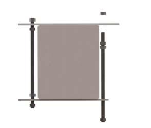
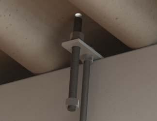
10 M12 Threaded Bar M10 Threaded Bar Page 10 of 13

 over the threaded bar and push down against the")
11 1. Fit the Concrete Purlin Bracket (g) around the purlin as shown on page 10. Pre-drill the roofing sheet 2mm bigger than the size of the threaded bar. 2. Once the M12 threaded bar has been threaded through the roofing sheet, fit the EPDM Washer (h) over the threaded bar and push down against the roofing cover to provide the weatherproof seal. Tighten 1x M12 Serrated Nut (i) over the top of the EPDM Washer (h). 3. Place 1x M12 Serrated Nut (i) over the threaded bar, together with 1x Cross Connector (j) and another 1x M12 Serrated Nut (i), as shown below. Page 11 of 13
 and turn clockwise until it locks, then secure it by tightening the serrated nut.")
12 4. Attach the Cross Connector (j) to the Mounting Rail (d) by sliding the T Bolt into the side channel of the Mounting Rail (d) and turn clockwise until it locks, then secure it by tightening the serrated nut. Page 12 of 13

13 Page 13 of 13
Mounting systems for solar technology
 Mounting systems for solar technology ASSEMBLY INSTRUCTIONS Crosshook 3S CrossHook 4S GB Table of contents TABLE OF CONTENTS THE COMPANY SAFETY REGULATIONS MATERIALS REQUIRED TOOLS REQUIRED ASSEMBLY 2
Mounting systems for solar technology
 Mounting systems for solar technology ASSEMBLY INSTRUCTIONS Roof Fastener System CrossHook 2G GB Table of contents TABLE OF CONTENTS THE COMPANY SAFETY REGULATIONS MATERIALS REQUIRED TOOLS REQUIRED ASSEMBLY
MANUAL MOUNTING SYSTEM FOR CORRUGATED ROOF
 MANUAL MOUNTING SYSTEM FOR CORRUGATED ROOF EN mounting system for corrugated roof for solar panels in portait setup (cross-system) ESDEC BV 2015 TABLE OF CONTENT 1. Introduction 1 2. General installation
MANUAL MOUNTING SYSTEM FOR BITUMEN / EPDM
 MANUAL MOUNTING SYSTEM FOR BITUMEN / EPDM EN mounting system for insulated pitched roof Bitumen / EPDM for solar panels landscape setup ESDEC BV 2015 TABLE OF CONTENT 1. Introduction 1 2. General installation
Roof fastener. Perfectly thought out for every roof
 Roof fastener Perfectly thought out for every roof 1 Welcome to the world of clever solutions Solutions for every roof In our production areas we produce all needed components for the sub construction
On-Roof Mounting Sets for Flat-Plate Collectors
 Engineering Submittal Sheet Installation sets for collectors Fig. 1 Installation set for 2 collectors 1 basic installation set, 1 extension installation set Basic installation set for each collector array
Installation Instructions for Solar Snow Pad (SSP-T-3)
") Installation Instructions for Solar Snow Pad (SSP-T-3) Warning- Do not use this product on solar arrays where the calculated array snow loads exceed 50 pounds per square foot (psf). Most solar panels are
Installation Instructions for Solar Snow Pad (SSP-T-3) Warning- Do not use this product on solar arrays where the calculated array snow loads exceed 50 pounds per square foot (psf). Most solar panels are
SecuAnch Roof Anchor System
 Height Safety Products Email: marketing@fallprotec.com SecuAnch Roof Anchor System 1 Presentation The SecuAnch lifeline is designed to be permanently installed on buildings and other structures where maintenance
Installation of the JD 900 Series Flex Grain Platform Auger Trough Liner Kit
 www.polyskid.com P. O. Drawer 349, Monticello, GA. 31064 Phone: 800-542-7659 Fax: 706-468-2881 E-Mail: polytech@polyskid.com Installation of the JD 900 Series Flex Grain Platform Auger Trough Liner Kit
Alpha + On-Roof System Installation manual
 810-0116 Alpha + On-Roof System Installation manual Content Alpha + A stroke of genius with a plus 1 Introduction 2 1.1 Short Description 2 1.2 About These Instructions 2 1.3 Warnings 3 1.4 Safety 3 2
SolarMount (E)volution
volution") SolarMount (E)volution SOLARMOUNT (E)VOLUTION: THE BEST JUST GOT BETTER. Engineering, Excellence, and Ease. Performance Engineered for versatility and reduced installation time, SolarMount (E)volution
SolarMount (E)volution SOLARMOUNT (E)VOLUTION: THE BEST JUST GOT BETTER. Engineering, Excellence, and Ease. Performance Engineered for versatility and reduced installation time, SolarMount (E)volution
FS Uno mounting instructions. 2 Pile driving (Ramming) 5. 6 Components list Torque specifications 15
 5. 6 Components list Torque specifications 15") FS Uno System Mounting instructions CONTTS Page 1 General - Safety, planning and tools 2 2 Pile driving (Ramming) 5 3 Rack overview - Components and fasteners 6 4 Mounting of the individual assembly groups
FS Uno System Mounting instructions CONTTS Page 1 General - Safety, planning and tools 2 2 Pile driving (Ramming) 5 3 Rack overview - Components and fasteners 6 4 Mounting of the individual assembly groups
orientation Conergy SunTop Instructions for professional installation
 On-roof Framed modules Portrait orientation Landscape Three-tab Shingle Plain tile Slate Double Roman tile Metal roof Material warranty orientation Conergy SunTop Instructions for professional installation
System FS Duo Mounting Instruction. 1 General 2. 2 Pile driving 3. 3 Mounting the individual assembly groups 4. 4 Torque specifications 7
 System FS Duo Mounting instructions CONTENTS Page 1 General 2 2 Pile driving 3 3 Mounting the individual assembly groups 4 4 Torque specifications 7 5 Module mounting 8 6 Tolerances 8 1 / 8 1 General 1.1
INSTALLATION INSTRUCTIONS ENGLISH
 INSTALLATION INSTRUCTIONS ENGLISH Safety instructions 04 General notes 07 Material & tool requirements 08 System overview 10 installation of HANGER BOLTS 12 Maintenance 23 04 INTENDED USE Creotecc mounting
Large Wood Windmill Assembly Instructions
 CROW S NEST (TOP VIEW) TOWER (SIDE VIEW) 0 QTY 2 2 ITEM QTY 2 QTY QTY 8 QTY 8 QTY 4 TOP TOP TOP 47 9 QTY 4 QTY 4 QTY 4 QTY 4 QTY 4 ITEM 6 ITEM 7 ITEM 8 ITEM 3 ITEM 9 ITEM 4 ITEM 2 ITEM 5 47 Leg QTY 4 42.5
Roof Mount Ground Mount Specialised Clamps Spares Application Notes
 DPA Solar Racking Solutions Solar PV Racking Catalogue Roof Mount Ground Mount Specialised Clamps Spares Application Notes www.dpasolar.com.au 1300 447 500 Rails & Splices Page 3 Mid & End Clamps Page
On-roof system Alpha + Product catalogue
 On-roof system Alpha + Product catalogue Contents ALPHA +... 3 1. ALPHA + BASE RAILS... 4 2. ALPHA + SPLICES... 5 3. ALPHA + TELESCOPING END PIECES... 6 4. ALPHA + INTER-MODULE CLAMPS AND MODULE END CLAMPS...
Next Level Security. This 2-tier locker ships flat to save on freight, comes in galvanized and powder coat finish options, and has a modular design.
 T WO - T I E R B IK E LO C K E R Next Level Security We take long-term bicycle storage to new heights with the new Dero Two-Tier Bike Locker. It is easy to load and provides a space-saving solution to
CONTENTS TOOL LIST U P S I D E I N N O V A T I O N S, L L C RAMP AND STEP SYSTEM ASSEMBLY INSTRUCTIONS. Revised: June 2013
 U P S I D E I N N O V A T I O N S, L L C RAMP AND STEP SYSTEM ASSEMBLY INSTRUCTIONS TOOL LIST Required Tools: - Reciprocating Saw with Metal Cutting Blade - Drill - 7/16 Drill Bit for Metal Drilling -
INSTRUCTIONS FOR: GALVANIZED STEEL SHED MODEL No: GSS1515
 INSTRUCTIONS FOR: GALVANIZED STEEL SHED MODEL No: GSS1515 Thank you for purchasing a Sealey product. Manufactured to a high standard this product will, if used according to these instructions and properly
Track Rack. * Track Racks are not lockable
 The Track Rack s unique staggered, sliding hook design creates the greatest parking efficiency while still providing easy access to any particular bike. When adding or removing a bike to the rack, simply
Clopay Models 835/837 Sliding Door System Installation Guide
 Clopay Models 835/837 Sliding Door System Installation Guide The aim of this instruction is to guide you through the process of construction and fitting of Sliding Doors. Due to the number of sizes available
Fig. 2 DORMA-Glas Stand/Issue 02/03 Seite/Page 1/7
 FSW Installation instructions Track rail 75 x 72 mm 1. Ceiling substructure and installation of the track rail (Fig. 1): The track rail must be bolted over its entire length (including the stacking track
Installation Guide Simplicity Alfresco. V1.9 Lu070318
 0333 305 5272 www.canoports.co.uk Installation Guide Simplicity Alfresco V1.9 Lu070318 Tools Required Below is a list of tools that you will require to install your the Simplicity Alfresco System. Cordless
 SUPREME WALL GARDEN ASSEMBLY INSTRUCTIONS 24/08/16 www.hallsgreenhouses.com Please refer to website for the most up to date instructions. SAFETY WARNING 1. Always wear protective glasses, shoes, gloves
1 of 9 SITE PLAN modules at 325W kw. Sample GAMECHANGE SOLAR. Sample. Sample AERIAL VIEW. Array Information. Design Information.
 AERIAL VIEW Array Information PV Modules Racking Manufacturer Hyundai Gamechange Racking Model HiS-S325TI 5-Degree GC Grid-Lite Dimensions." x 39.29" x.9" Weight 5. lbs Quantity 224 224 modules at 325W
Assembly Instructions 10 X 10 Aluminum Frame Building
 Assembly Instructions 10 X 10 Aluminum Frame Building 27 97 9 8 47 36 74 52 10 10 X 10 Square Building W/ Dome Includes: The Steel Entry Door with a Dead Bolt Lock assembly and Aluminum Door Frame. Metal
Version 2016_1.1 VICTORIAN ASSEMBLY INSTRUCTIONS. Victorian Vi-23, 34, 36
 Version 2016_1.1 VICTORIAN ASSEMBLY INSTRUCTIONS Victorian Vi-23, 34, 36 PRODUCT INFORMATION Dear customer, Thank you for buying a high-quality aluminium greenhouse. REMARKS The drawings in these instructions
Rayport G Eco Dealer Kit
 Rayport G Eco Dealer Kit Installation Guide www.aetenergy.com Supporting a Cleaner, Greener Tomorrow 1. Table of Contents 1. Table of Contents P2 2. Installer Notes P3 3. Parts List P4-7 4. Tool List P8
Motorized Tower Raising System Manual
 Motorized Tower Raising System Manual Introduction and Safety Guidelines Important! Read through the manual in its entirety prior to assembly and installation of the motorized tower raising system. WARNING:
Baby Grande or Grande Crank Shade with Cables and Housing Installation Instructions
 Baby Grande or Grande Crank Shade with Cables and Housing Installation Instructions Tools Needed Drill 3/8 Metal Drill Bit Screwdriver (Flat & Phillips) Measuring Tape Pencil 4 Level Plumb Line ¼ Masonry
Rayport G Eco Ballasted
 Rayport G Eco Ballasted Dealer Kit Installation Guide Contents 1. Installer Notes..... P2 2. Parts List........ P3-6 3. Tool List.... P7 4. Assembly.... P8-16 www.aetenergy.com Supporting a Cleaner, Greener
Before fitting door, check opening size and squareness of timber frame. The door is made smaller to give correct clearance within the frame.
 Slideaway Single & Maximizer Door Gear INSTALLATION INSTRUCTIONS 11 This garage door has been designed to be as as easy as possible to use, service and automate when installed correctly. Please therefore
ALUMINIUM SOLAR MOUNTING SYSTEM. Components catalogue FOR ALL TYPES OF ROOFS AND SITES
 Components catalogue MOUNTING RAILS CARRIERS FOR RAILS FASTENERS BOLTS AND NUTS CLIPS FLAT ROOFS STRUCTURES FREE FIELD SYSTEMS COMPLEX ROOFS SYSTEMS ALUMINIUM SOLAR MOUNTING SYSTEM FOR ALL TYPES OF ROOFS
SolarMount-I INSTALLATION MANUAL Broadway Boulevard NE Albuquerque, NM USA A HILTI GROUP COMPANY
 SolarMount-I INSTALLATION MANUAL 2011 by Unirac, Inc. All rights reserved. Pub 110518-1ii, May 2011 A HILTI GROUP COMPANY R 1411 Broadway Boulevard NE Albuquerque, NM 87102-1545 USA IMPORTANT! Unirac Inc.
Mounting systems for solar technology
 Mounting systems for solar technology ASSEMBLY INSTRUCTIONS Roof Fastener Pan Tile GB Table of contents TABLE OF CONTENTS THE COMPANY SAFETY REGULATIONS MATERIALS REQUIRED TOOLS REQUIRED ASSEMBLY 2 3 4
FLIP TARP SINGLE & DOUBLE UNDERBODY TRAILERS
 1-800-248-7717 1002 N. 15th Street, Middlesboro, KY 40965 FLIP TARP SINGLE & DOUBLE UNDERBODY TRAILERS INSTALLATION INSTRUCTIONS Congratulations on your purchase of a Mountain Flip Tarp Trailer system.
Installation Guide Contemporary Alfresco V1.3 LU
 Installation Guide Contemporary Alfresco V1.3 LU 010818 Tools Required Below is a list of tools that you will require to install you're the Contemporary Alfresco System. Cordless Drill Mastic Gun Spirit
SolarWedge. Installation Manual Date Modified: 9/17/07 WARNING SAFETY. Tool List
 APPLICATION: The product line provides an easy -to-install and economical solution for a 5, 10 or 15 degree tilted roof mounted system. integrates with Professional Solar s (ProSolar) patented top-down
Assembly Instructions 10 X 10 Aluminum Roof Support
 Assembly Instructions 10 X 10 Aluminum Roof Support Aluminum Roof Support Bolt Package 16-5/16 X 2 ¼ SS Bolt 24-5/16 X 1 SS Bolt 40-5/16 SS Nylon Lock Nuts 16-5/16 SS Flat Washers 28-4 ½ Wood Screws 36-1
May 14, Installation Manual
 May 14, 2012 Installation Manual Contents MAG TRACKER Components...1 Mount Installation...7 Module Installation & Grounding...11 Maintenance...14 Warranty......14 Contact Information......14 May 14, 2012
Baby Grande or Grande Crank Shade with Cables and Housing Installation Instructions
 Baby Grande or Grande Crank Shade with Cables and Housing Installation Instructions Tools Needed Drill 3/8 Metal Drill Bit Screwdriver (Flat & Phillips) Measuring Tape Pencil 4 Level Plumb Line ¼ Masonry
INSTRUCTIONS FOR: GALVANIZED STEEL SHED MODEL No: GSS1508
 INSTRUCTIONS FOR: GALVANIZED STEEL SHED MODEL No: GSS1508 Thank you for purchasing a Sealey product. Manufactured to a high standard this product will, if used according to these instructions and properly
AWNING SYSTEM INSTALLATION INSTRUCTIONS ALL VERTICAL WALLS
 INSTALLATION MANUAL AWNING SYSTEM INSTALLATION INSTRUCTIONS ALL VERTICAL WALLS TABLE OF CONTENTS Table of Contents... 3 Components... 4 System Components... 6 Attachment Components... 7 Module Compatibility...
PV-ezRack Solar Terrace II-A Installation guide
 PV-ezRack Solar Terrace II-A Installation guide Contents 1 Introduction..2 2 Tools & Components.3 3 System overview.4 4 Installation steps..7 5 Notices and Safety Precautions.. 14 6 Project Case...16 7
Step by Step Installation Instructions. Poly Shutters. Customer Service or visit us online at smithandnoble.com
 Step by Step Installation Instructions Poly Shutters Customer Service 800.248.8888 or visit us online at smithandnoble.com Thank you for purchasing from smith+noble. Your new window treatments have been
Sport-Thieme. Full-Size Goal. Assembly instructions. 7,32x2,44 m, Portable
 Assembly instructions Sport-Thieme 7,32x2,44 m, Portable Art.-Nr.: 115 0793 257 7207 Full-Size Goal 0218214 2018 Sport-Thieme GmbH D-38367 Grasleben Germany sport-thieme.com info @sport-thieme.com Phone:
ULTRA SPACE SAVER SQUARED Installation Instructions
 Installation Instructions The Ultra Space Saver Squared has several steps for installation. Note that the single and double sided setups and parts are different. Make sure you follow the instructions according
Dura-Lock Roof System
 DLR-14 Dura-Lock Roof System Assembly and Installation Instructions Read the instructions before starting the job. They explain the steps required to produce a finished product that will meet factory specifications.
12ft Octagon Bayside Gazebo Assembly Manual
 We recommend reviewing this Assembly Manual thoroughly before starting this project. Become familiar with the tools required and where and when assistants are necessary. If you re planning on finishing
Bumper Sign INSTALLATION INSTRUCTIONS
 Bumper Sign INSTALLATION INSTRUCTIONS BUMPERSIGN TOOL CHECKLIST SDS MAX Rotary Hammer Drill Marker/Pencil SDS MAX 1 Carbide Drill Bit Tape Measure Torque Wrench with ½ Drive Power Source Vacuum ½ Drive
HOMECREST STYLE SLING 3J300 Installation Instructions
 1 HOMECREST STYLE SLING 3J300 Installation Instructions Before beginning, take careful note of how the chaise is assembled, particularly the adjustment hardware. An additional set of hands to help during
INSTALLATION INSTRUCTIONS TRI-ROOF. energy for a better world
 energy for a better world INSTALLATION INSTRUCTIONS TRI-ROOF The flexible roof integration system Compatible for framed module types* Simple exchange of modules Replaces existing roofing Special profiles
Patented Rail-Free Mounting System for Composition/Asphalt Shingle Roofs
 Quick Start Guide Patented Rail-Free Mounting System for Composition/Asphalt Shingle Roofs R ESPECT T HE R OOF Quick Rack Components & Tools Components are pre-assembled and ready for installation right
ROOFSAFE ANCHOR & CABLE
 Installation Instructions ROOFSAFE ANCHOR & CABLE THE ULTIMATE IN FALL PROTECTION MANUAL Contents Guidelines for Installation 3 Top Bolt Installation 4 Toggle Installation 5 Concrete Installation 6 Component
System FS Uno Mounting Instruction. 1 General 2. 2 Pile driving 3. 3 Mounting the individual assembly groups 4. 4 Torque specifications 6
 System FS Uno Mounting instructions CONTENTS Page 1 General 2 2 Pile driving 3 3 Mounting the individual assembly groups 4 4 Torque specifications 6 5 Module mounting 6 6 Tolerances 7 1 / 7 1 General 1.1
Installation Manual FLUSH MOUNT - Shingle, Slate,etc. Questions? Call Us! +1 (800)
") www.trasnowandsun.com S Installation Manual FLUSH MOUNT - Shingle, Slate,etc. At TRA Snow and Sun we engineer and layout each project upon request free of charge. Just give us the project details and we
www.trasnowandsun.com S Installation Manual FLUSH MOUNT - Shingle, Slate,etc. At TRA Snow and Sun we engineer and layout each project upon request free of charge. Just give us the project details and we
Installation Instructions
 Installation Instructions Ceiling Mount Bracket for DLP Based Projectors (for High Ceilings) Model No. ET-PKD100H Contents Important Safety Notice.................. 2 For DLP Based Projector: PT-D10000
PV SLATE ROOF INSTALLATION GUIDE
 The PV Slate roof tile is designed to integrate into a roof clad with either natural or imitation slates. Initial Roof Batten Layout. The roof should be battened using 50x25mm batten at a spacing of 270mm.
Queen Wingback Bed King Wingback Bed
 Parts and Hardware List A. Side Rails with Attachment Hooks 2 pcs B. Foot Rail 1 pc C. Head Rail 1 pc D. Center Support Slat 1 pc E. Leg Supports 3 pcs F. Support Slats 4 pcs G. Flat Washers 8 pcs H. Lock
Kwik-Lock. Installation Instructions. Attention Dealers: Please give this owners manual to the customer when the product is delivered.
 Serving the Truck & Trailer Industry Since 1944 Installation Instructions Attention Dealers: Please give this owners manual to the customer when the product is delivered. Call 800-535-9545 www.aeroindustries.com
Installation Procedures
 Installation Procedures Nutec Bigsix Roofing sheets properly laid and fixed in accordance with recommendations will provide many years of trouble-free protection from the elements. Failure to follow these
GALVANIZED SHED GREEN 2.3 X 2.3 X 1.9m
 INSTRUCTIONS FOR: GALVANIZED SHED GREEN 2.3 X 2.3 X 1.9m MODEL NO: GSS2323G Thank you for purchasing a Sealey product. Manufactured to a high standard, this product will, if used according to these instructions,
Step by Step Installation Instructions. Poly Shutters. Customer Service or visit us online at smithandnoble.com
 Step by Step Installation Instructions Poly Shutters Customer Service 800.248.8888 or visit us online at smithandnoble.com THANK YOU for purchasing from smith+noble. Your new window treatments have been
BMW E46 Coupe 3dr MP Bolt in (BMW Race Days Only) Roll Cage (B045) Fitting Instructions
 Roll Cage (B045) Fitting Instructions") BMW E46 Coupe 3dr MP Bolt in (BMW Race Days Only) Roll Cage (B045) Fitting Instructions Unwrap the mounting points/ends of the roll cage and unpack the individual fitting kits. Try to leave wrapping on
BMW E46 Coupe 3dr MP Bolt in (BMW Race Days Only) Roll Cage (B045) Fitting Instructions Unwrap the mounting points/ends of the roll cage and unpack the individual fitting kits. Try to leave wrapping on
10ft Octagon Bayside Gazebo Assembly Manual
 We recommend reviewing this Assembly Manual thoroughly before starting this project. Become familiar with the tools required and where and when assistants are necessary. If you re planning on finishing
SolarMount-I INSTALLATION MANUAL
 SolarMount-I INSTALLATION MANUAL 2010 by Unirac, Inc. All rights reserved. Pub 100621-1ii, June 2010 R A HILTI GROUP COMPANY 1411 Broadway Boulevard NE Albuquerque, NM 87102-1545 USA IMPORTANT! Unirac
Ledger Board Lean-to Instruction Manual
 Ledger Board Lean-to Instruction Manual for 18 x 24 2 x 8 /12 6 covers ROOF ONLY ROOF WITH GABLES 2-SIDED FRAME ONLY 2-SIDED WITH GABLES Our unique assembly process quickly transforms the individual pieces
N. 15th Street, Middlesboro, KY FLIP TARP DUMP BODY INSTALLATION INSTRUCTIONS
 1-800-248-7717 1002 N. 15th Street, Middlesboro, KY 40965 FLIP TARP DUMP BODY INSTALLATION INSTRUCTIONS Congratulations on your purchase of a Mountain Flip Tarp Dump Body tarping system. With tarping systems
Solar. mounting solutions. system components.
 Solar mounting solutions system components ABOUT REMOR REMOR Solar is the largest manufacturer of solar mounting systems in Poland. throughout the entire Europe, supplying mountings to over 200 MW of PV
GIRTS ON BACK OF BUILDING
 GIRTS ON BACK OF BUILDING ALL GIRTS ARE 1 1/2 SQUARE TUBE. GIRT LENGTHS FOR 12, 20, 24, AND 30 WIDE BUILDINGS: ON 12 WIDE BUILDINGS GIRTS ARE 67 3/4 LONG ON 20 WIDE BUILDINGS GIRTS ARE 56 3/4 LONG ON 24
Ledger Board Lean-to Instruction Manual
 Ledger Board Lean-to Instruction Manual for 18 x 24 2 x 8 covers Our unique assembly process quickly transforms the individual pieces into a finished structure that will give you a lifetime of service.
Pole Mount Installation Manual
 Pole Mount Installation Manual Thank You for Choosing AIMS Power! 1. AIMS Power is a leading supplier of solar products, specializing in PV mounting systems. We ensure our products are manufactured to
ORP-R1 Mini/Regular: Basic / J-Connection / M-Connection
 ORP-R1 Mini/Regular: Basic / / Construction Manual Thank you for purchasing our product. The indication symbols in this construction manual are for you to construct the product safely and properly and
Tools Needed Hardware Provided (per shade) Hardware Needed
 Hardware Needed") Baby Grande or Grande Motorized (XQ5 Premium) Shade with Cables and Housing Installation Instructions Tools Needed Hardware Provided (per shade) Hardware Needed Drill 3/8 Metal Drill Bit Measuring Tape
Baby Grande or Grande Motorized (XQ5 Premium) Shade with Cables and Housing Installation Instructions Tools Needed Hardware Provided (per shade) Hardware Needed Drill 3/8 Metal Drill Bit Measuring Tape
INSTALLATION GUIDE DUOFUSE SLAT WALL SYSTEM
 06/2013 ENG 1 INSTALLATION GUIDE DUOFUSE SLAT WALL SYSTEM The Duofuse wood composite slat wall system is much more durable than wooden fences, and correct installation is necessary to enjoy the fences
SunPower Installation Manual
 SunPower SF System Planning and Assembly SunPower SUNPOWER CORPORATION WWW.SUNPOWERCORP.COM Pub #101001-SP2 October 2010 - Rev. 8 2010 by SunPower, Corp All rights reserved. Part I. Scope, components,
STEP 1 STEP 2 LEVELER KIT OPTION MOBILE CASTER KIT OPTION
 B SERIES INDUSTRIAL BENCHES TOOLS REQUIRED FOR ASSEMBLY Socket set, Open end wrench set, Cordless drill with 3/8" socket bit (Magnetic recommended). BEFORE ASSEMBLY Read through the assembly instructions
Installation Instructions
 Installation Instructions For Models: Model Number / Description File Name 1540 Classic Series P-Lam Toilet Partitions 1540.pdf 1 INSTALLATION INSTRUCTIONS LAMINATED PLASTIC TOILET PARTITIONS 1540 Classic
DOCK WEDGE - STANDARD
 DOCK WEDGE - STANDARD INSTALLATION INSTRUCTIONS WOOD HEADER READ ALL INSTRUCTIONS BEFORE INSTALLING SEAL. SUPER SEAL MFG. LTD. WILL NOT BE HELD RESPONSIBLE FOR IMPROPER INSTALLATION OF ANCHORING DEVICES,
TREX POST MOUNT DECKING AND CONCRETE
 TREX POST MOUNT DECKING AND CONCRETE for Pressure-treated Wood Framing LOCATION AND INSTALLATION OF POST MOUNTS IMPORTANT NOTES:» EACH POST MUST BE ATTACHED AS SHOWN TO ENSURE A CODE COMPLIANT AND SAFE
Rayport G Eco Dealer Kit
 Rayport G Eco Dealer Kit Installation Guide Contents 1. Installer Notes..... P2 2. Parts List........ P3-7 3. Tool List.... P8 4. Assembly.... P9-19 www.aetenergy.com Supporting a Cleaner, Greener Tomorrow
FABA. Installation Instructions. Conductor Bar System. Publication #FABA-03 3/1/04 Part Number: Copyright 2004 Electromotive Systems
 FABA Conductor Bar System Installation Instructions Publication #FABA-03 3/1/04 Part Number: 005-1062 Copyright 2004 Electromotive Systems 1S 100 Z Installation Instructions Contents: Basic Diagram - -
ULTRA SPACE SAVER Installation Instructions
 Installation Instructions The Ultra Space Saver has several steps for installation. Note that the single and double sided setups and parts are different. Make sure you follow the instructions according
IMPORTANT -- SPECIAL INSTALLATION INSTRUCTIONS
 IMPORTANT -- SPECIAL INSTALLATION INSTRUCTIONS ** READ ALL INSTALLATION INSTRUCTIONS BEFORE STARTING!** If at any point, you have questions, call 1-800-851-0865...(The manufacturer will not be responsible
BLACK WIDOW COMPOSITE
 PAGE-1 UPDATED 3-6-2015 REV.1 BLACK WIDOW COMPOSITE Detailed installation manual PAGE-2 UPDATED 3-6-2015 SpiderRax, Inc. REVISION PAGE Installation Manual For BWC-S, BWC-B,BWC-F DATE PAGES REASON OLD LEVEL
Cable Hanging Instruction Manual
 Tri-States Grain Conditioning, Inc. Cable Hanging Instruction Manual There are several types of grain storage tanks and bins. Parts of these instructions may be modified to fit the circumstances. Care
Curium 19H Installation Instructions & Parts List
 Curium 19H Installation Instructions & Parts List Illustration Curium 19H Right Hand Page 1 of 15 01/07/2016 Revision 2.1 IMPORTANT This shower screen / enclosure must be installed by suitably qualified
Curium 19.4H Installation Instructions & Parts List
 Curium 19.4H Installation Instructions & Parts List Illustration Curium 19.4H Right Hand Page 1 of 21 30/06/2016 Revision 1.0 IMPORTANT This shower screen / enclosure must be installed by suitably qualified
The Mind Project s Iris 1 Robotic Arm. Packing List Assembly instructions
 The Mind Project s Iris 1 Robotic Arm Packing List Assembly instructions Packing list Below you will find pictures and descriptions of each part. It may be helpful to take each piece out of the bag and
Connect Transit Shelter
 Tools Required *denotes special tools required Connect Shelter, 8ft Connect Shelter, 12ft *Soft, non abrasive protective surface such as a furniture blanket *Source of compressed air (for thorough dust
GrowSpan Series 500 Door Kits
 GrowSpan Series 500 Door Kits Double Swinging Door Finished Grade Finished Grade Diagram shows a double-swinging door centered and installed in an end wall frame. The door kit includes materials for the
Simotec. 13.i
 Products: Framo 80 13.0 Products: Framo 80 13.1 Products: Structural Elements 100/120 13.2 Products: Pipe Shoes 13.3 Framo 80: Beam Section and Screw 13.4 Framo 80: Cantilever Bracket and End Support STA
INSIDE PANEL NOT SHOWN TO DETAIL ANCHORING SYSTEM
 SIX INCH ALPHA MODULE INSTALLATION KEWAUNEE SCIENTIFIC CORPORATION SIX INCH ALPHA MODULE ANCHORING SYSTEM After Alpha module has been set in desired location. Adjust the four adjustment bolts until the
Assembly Guide for Series 500 Ridge Vent Kits
 Assembly Guide for Series 500 Ridge Vent Kits Photo shows a sample ridge vent as installed on a greenhouse. Actual building and ridge vent length may differ. 2014 ClearSpan All Rights Reserved. Reproduction
12, 14 & 16 Wide Enclosure Assembly Guide
 www.rmfiberglass.com 12, 14 & 16 Wide Enclosure Assembly Guide RM Products Ltd 1-800-363-0867 www.rmfiberglass.com Table of Contents 1. Handling and Storage page 3 to 5 2. Parts and Tools List page 7 3.
INSTALLING INVISIRAIL GLASS PANELS POST INFORMATION... 2 PRE-INSTALLATION... 2
 Contents POST INFORMATION... 2 PRE-INSTALLATION... 2 STEP A1: MEASURING FOR INVISIRAIL CUSTOM GLASS PANELS (skip if using Standard Sized Panels)... 2 STEP A2: GATHER ADDITIONAL TOOLS/SUPPLIES... 2 STEP
Installation Manual for The Asphalt/Bitumen Shingle Roof Hook System
 Installation Manual for The Asphalt/Bitumen Shingle Roof Hook System (F-IMG-1534-SolNV) Installation of Asphalt/Bitumen Shingle Roof Hook System Installing Rail / Purlin System Installing Cross Rail System
10 x 10 Flat Top Two Tone Pergola
 0 x 0 Flat Top Two Tone Pergola Models: Bordeaux ASSEMBLY GUIDE OPTIONAL ACCESSORIES Arch Kit System ( Arches) Privacy Fence Panel System ( Panels & Middle Post) Bolt Down Bracket Kit ( for Pergola) Ver.0-00