12ft Octagon Bayside Gazebo Assembly Manual
|
|
|
- Ariel Hubbard
- 5 years ago
- Views:
Transcription
1 We recommend reviewing this Assembly Manual thoroughly before starting this project. Become familiar with the tools required and where and when assistants are necessary. If you re planning on finishing the Gazebo in a weekend, we recommend completing up to Step 41 on your first day. 12ft Octagon Bayside Gazebo Assembly Manual Feb 23rd, 2015 Revision #21 Thank you for purchasing a 12 ft Octagon Panelized Gazebo. Please take the time to identify all the parts prior to assembly. Safety Points and Other Considerations Our products are built for use based on proper installation and normal residential use, on level ground. Please follow the instruction manual when building your Gazebo and retain the manual for future maintenance purposes. Some of the safety and usage measures you may wish to consider include: -snow load ratings vary by geographical location. If heavy or wet snowfall occurs, it is advisable to sweep the snow off the roof(s). -if the product is elevated, any structural and building code requirements are solely the customer's responsibility, and should be abided by. -in high or gusty wind conditions it is advisable to keep the structure securely grounded. -have a regular maintenance plan to ensure screws, doors, windows and parts are tight. Customer agrees to hold Outdoor Living Today Partnership and any Authorized Dealers free of any liability for improper installation, maintenance and repair. In the event of a missing or broken piece, simply call the Outdoor Living Today Customer Support within 30 days of the delivery of your purchase. It is our commitment to you to courier replacement parts, free of charge, within 10 business days of this notification. Replacement parts will not be provided free of charge after the 30 day grace period. Page 1
2 Thank you for purchasing our 12ft Octagon Bayside Gazebo Kit. Please take the time to identify all the parts prior to assembly. Parts List A. Floor Joist Section (Page 4-11) 1-5 1/4 - Diameter Octagon Core Block 8-1 1/2 x 5 1/2 x 68 7/16 - Main Floor Joist 8-1 1/2 x 5 1/2 x 23 13/16 - T Post Mount Plate / Main Floor Joist 8-1 1/2 x 5 1/2 x 53 1/16 - Mid Floor Joist 8-1 1/2 x 5 1/2 x 13 1/8 - Interior Core Brace - angle cut on ends 8-1 x 5 1/2 w x 58 3/8 - Outer Rim Joists 8-3 1/2 x 3 1/2 x 91 - Posts - Angle Cut on Top / Drilled on Bottom 1 - Plywood Post Spacing Template - Angle cut on ends B. Rafter Section (Page 12-14) 8-3 1/2 x 3 1/2 x 74 1/8 - Corner Rafters (30 & 22 1/2 degree cut) 8-3 1/2 x 3 1/2 x 70 - Mid Rafters (31 degree cut both ends) 8-1 1/2 x 6 x 14 7/8 - Octagon SkyBox (Cut,Dado and Drilled) C. Rail Section (Page 15-19) /8 x 36 - Hand Rail Section 14-5/8 x 3 1/8 x 40 - Hand Rail End Caps - Dog Ear and Router edges /8 x 10 - Upper Rail Section 8-5/8 x 3 1/8 x 15 1/4 - Upper Rail End Caps -Right Side (Angle Cut One End with Hole) 8-5/8 x 3 1/8 x 15 1/4 - Upper Rail End Caps -Left Side (Angle Cut One End with Hole) D. Floor Section (Page 20-23) 8 - Pre-assembled Deck Floor Panels - Triangular Shaped 8-1 x 5 1/2 x 60 1/2 - Perimeter Deck Board- notched for Post 8-1 x 5 1/2 w x 14 1/8-2nd to last Deck Board 8-1 x 5 1/2 w x 9 1/2 - Last Deck Board 1-1 x 12 - Octagon Center Deck Piece E. Roof Section (Page 24-29) 16 - Roof Panels (8 left / 8 right) /2 x 5 1/2 x 22 5/8 - Corner Brackets - 8 left / 8 right 8 - Facia Boards - 1 x 4 1/2 x 64 1/2 long - Angle Cut on Ends F. Cupola Parts List (Page 30-34) 8 - Side Rail Sections 1 - Small Core Block- Octagon 8-1 1/2 x 1 1/2 x 24 - Rafter - (Angle Cut Both Ends) 8-3/4 x 1 1/2 x 17 7/8 - Facia 8 - Small Roof Panels 24 - Cupola Ridge Caps (2 1/2 wide V shaped) 8-16 long / /2 long / 8 1/2-10 angle ends 1 - Top Cap & Ball Top G. Miscellaneous Section (Page 35-37) 32 - Filler Shingles- Main - 5 1/2 x Filler Shingles - Top - 5 1/2 x 11 1/2 8 - Facia Corner Detail Plates (Small) 8 - Rim Joist Corner Detail Plates (Large) 88 - Ridge Cap Shingles - (8 need to be trimmed for last row) Page 2


 Hammer Screw")

3 12 BAYSIDE GAZEBO HARDWARE SHEET Hardware Kit (Provided) Note: Hardware below shown as actual size. In Florida, additional hardware may be required that is not included in kit due to hurricane winds. Please check with local building code to confirm /2 1 1/4 Finishing Shingle 2 Stainless Steel Square Drive Bit 5 1/2 Carriage Bolt x 40 Washers x 40 Nuts x 40 Tools Required (Not Provided) Hammer Screw Gun/Drill Tape Measure Wood Clamp Utility Knife Level Pliers Ladder 1/2 Wrench 1/8 Drill Bit Safety Equipment Required (Not Provided) Safety Glasses Work Gloves Page 3


4 A. Floor Section Long Main Floor Joist 68 7/16 long Measure to center of Plate T Post Mount with Holes Drilled Drilled Holes T Post Mount Plate 23 13/16 long 1. Locate both the Long Main Floor Joist and the T Post Mount Plate. Angle cut ends must be positioned to the outside. Pre-drilled holes will align with Posts later in Step 10. Please review this step to confirm correct T Post Mount Plate orientation. Use 4 - Carriage Bolts to align Joist with T Plate prior to attaching. Joist must be evenly spaced between bolts. Remove Carriage Bolts when correctly aligned. Joist evenly spaced between bolts. 2. With pieces properly orientated, screw T Plate and Joist together with 2-3 screws. Make sure pieces are flush with each other on the top and bottom. Complete all 8 Long Main Floor Joist and T Post Mount Plate Connections. Once again, check alignment prior to attaching together. 3. Locate the 5 1/4 Diameter Octagon Core Block. Place at end of one of the Long Main Floor Joists. Page 4


5 4. Position end of joist equally on one side of the Core Block. Angle screw with 3-3 screws from the top and sides. Joist and top of Core Block should sit flush with each other. Note, Drill 1/8 pilot holes in joist prior to screwing to prevent splitting. 5. Lay completed Core Block / Joist Assembly on flat level surface. 6. Position and angle screw the second joist assembly to opposite side of Core Block. 7. Continue to add Joist Assemblies to Core Block. Page 5

 and an Interior Core")


6 8. At this stage, your gazebo floor should look similar to the illustration to left. Important: To confirm Doorway location, refer to Step 16. Mid Floor Joist Interior Core Brace (angle cut on ends) 13 1/8 long 9. Locate and position a Mid Floor Joist (53 1/16 long) and an Interior Core Brace (13 1/8 long). Make sure the longer side of Core Brace is flush with the end of the joist and attach together with 2-3 screws. Once again, make sure Core Brace is centered and flush with joist. Complete all 8 attachments. 10. Set completed Mid Joist / Core Brace Assembly between the main Joist Assemblies but do not attach. Page 6


7 Do not attach until Step Position remaining Mid Joist / Core Brace Assemblies roughly between the main Joist Assemblies. Some adjusting will be necessary to form a symmetrical pattern. Angle Cut of Post (high side = inside) 12. Locate 3 1/2 x 3 1/2 Posts. Align first Post with four drilled holes in bottom aligned with T Post Mount Plates. Important: Be sure to align Post so top angle cut is high to the inside. 4 Holes Drilled in bottom of each Post Page 7


8 13. When holes are aligned, slide 4 - Carriage Bolts from the outside through Post and T Post Mount Plates. 14. Complete all four T Post Mount and Post Carriage Bolt attachments. Important: Once again, only snug Carriage Bolts at this stage. After Handrail and Upper Baluster Section are installed, come back and firmly tighten with wrench. 15. From the inside, slide a washer over bolt and tighten nut. Important: Only snug Carriage Bolts at this stage. After Handrail and Upper Baluster Section are installed, come back and firmly tighten all Carriage Bolts with a wrench. Must have Washer Page 8


9 2nd Post Plywood Post Spacing Template Door Way 16. Locate 2nd Post and Plywood Post Spacing Template. Align and secure Post to Joist Assembly as per Steps Using the Post Spacing Template, slide between posts as illustrated above. Push posts together tight against Template. Level with top of T Post Mount. See Step Locate one Outer Rim Joist (1 x 5 1/2 x 58 3/8 ) and position evenly from side to side between each Post. Level Rim Joist with top of T Post Mount. Screw Rim Joist to Post with 2-3 screws. Line up Mid Joist with Template Marker. 1-3 screw into Mid Rafter. 18. Before attaching opposite end of Rim Joist to Post, push Post tight against Template and then attach Rim Joist to Post with 2-3 screws. Line up Mid Joist with Mid Joist Template Marker and when correctly centered attach Mid Joist to Rim Joist with 1-3 screw. Page 9


10 3rd Post 19. Locate 3rd Post. Align and secure Post as per Steps Using the Post Spacing Template, position 3rd Post as per Step With 3rd Post correctly positioned, align and attach the Outer Rim Joist as per Step Angle Cut of Post (high side = inside) Any gaps between the ends Rim Joists will be covered by Rim Joist Detail Plates in Step Continue to attach Posts and Outer Rim Joists until all 8 are complete. Continue to use Post Spacing Template to confirm correct spacing. Remember- Align Post with high side to the inside. Page 10


11 Flush 22. Secure Core Brace Assembly to Main Joists with 4-3 screws. Make sure tops of Interior Core Brace and Main Joists are flush with each other as Decking will sit on this attached in Steps T Post Mount and Rim Joist at same height. 23. With all Mid Joist Assemblies secured, screw the T Post Mount into Rim Joist from inside with 2-3 screws on angles. Be careful to screw on angle so fastener does not come through Rim Joist. Complete all 8 sides. Important: Use a level to confirm all Floor Joists are level and that the overall Floor is level. Adjust as necessary. Support Floor Structure as required. Make sure that Posts are plumb. Check each Post in both directions with a level and adjust as required. Page 11


12 B. Rafter Section Caution - Next you will be installing Rafters. Rafters will be unstable until Upper Rails Sections are completed in Step 34. Rafters must be secured to Upper Rails and cannot be left unattended. 24. Locate 8 Skybox Pieces placing them with Dado cut facing out and to the top. Angled Ledge not accurately shown in picture. 2 screw 3 screws 3 screws 25. Position 2 pieces together so angle cut ends line up. When correctly aligned, screw together using 2-3 screws and 1 2 screw in top dado ledge as shown in left illustration. Attach remaining pieces to complete Skybox. V Notch in end Rafter 26. With your helper, lift the Octagon Skybox up with the dado or notch of the Skybox facing up. Place the V end of the Rafter in a corner of Skybox Octagon Skybox Notch on bottom Outdoor Living Today sales@outdoorlivingtoday.com Page 12


13 Important - Depending on the # of helpers you have available will determine how many rafters can be attached to Skybox prior to lifting up. Our illustration shows 3 Rafters = 2 additional helpers. Align Rafter Corners flush with ledge of Skybox. Screw from inside of Skybox into Rafter Flush with Ledge. 27. Align and secure Rafter end as illustrated above with 4-3 screws from the inside of the Skybox. Important- Be sure to support Skybox/Rafter Assembly as unit will be unstable until at least 3 Rafters are attached. 28. With your helper still supporting the Skybox/ Rafter Assembly, position and attach a second rafter as illustrated to the left and as per Step Complete 3rd Rafter attachment as shown above and as per Step 28. Important - Prior to lifting Rafters onto Posts, Upper Rails in Step 34 must be completed. Page 13


14 Post will sit in notch of rafter. 30. With the help of at least 2 assistants and Step Ladders, lift up your partially completed Skybox/ Rafter Assembly and place Rafters on top of Posts. The Post will sit in the notch of the Rafter. angle screw from side 31. Angle screw each Rafter/Post connection together with 1-3 screw from Post into Rafter. Slightly countersink screwhead. 32. Standing on ladders, position and attach a 4th Rafter to the Skybox and Post as per Step 27 and Step 31. Remember to align the Rafter correctly with Skybox ledge. 33. Complete remaining Rafter attachments and secure as per Step 27 and Step 31. Page 14
 and Upper Rail End Caps (8 left / 8 right).")


15 Left and Right Upper Rail End Caps. Outside View 34. Locate Upper Rail Sections (8) and Upper Rail End Caps (8 left / 8 right). Align Caps on Rail Section flush at the bottom and evenly spaced from side to side. See Pictures to the right to confirm alignment prior to attaching. Counter sunk hole to outside. Attach with 4-2 screws. Inside View Flush at bottom. C. Rail Section Evenly spaced from side to side. Important- Left and Right Upper Rail Ends Caps must be aligned correctly. Upon completion of first Rail Section, test fit Section as per Step Lift a completed Upper Rail Section up and place between the Rafters and Posts. Once Upper Rail alignment is confirmed, complete remaining Upper Rail Assemblies. Bang Carriage Bolts through holes. 36. Position Upper Rail Section so Pre-drilled holes in End Caps line up with Pre-drilled holes in Rafter. With holes aligned, carefully hammer Carriage Bolt through Upper Rail Section and Rafter. Do not secure washers and nuts of Carriage Bolts until Step 37. Page 15


 flush against")
16 Washer and Nut. 2nd Upper Rail Section 3rd Carriage Bolt 37. Lift a second Upper Rail Section into place and slide carriage bolt through End Cap hole. Place a washer over bolt and snug nut down. 38. Hammer in 3rd Carriage Bolt into left side of second Upper Rail Section as per Step Lift up, position and secure all remaining Upper Rail Sections using Steps Important - Snug Bolts down but don t over-tighten. 40. On your last Upper Rail Section, use Carriage Bolt from the first section to secure. Use Wood Clamps or have assistant push Rail / Rafter together. Inside of Skybox 2-3 screws Mid Rafter 42. Lift and position a Mid Rafter end (66 9/16 ) flush against Skybox. Use a straight edge to confirm same height as Corner Rafters. Position Mid Rafter centered on Skybox. When correctly positioned attach rafter to Skybox with 2-3 screws (screw from inside Skybox). Page 16


17 Mid Rafter Inside of Upper Rail Section 43. Center Mid Rafter on Upper Rail Section (the midpoint of the Upper Rail Sections is approximately 25 1/2 measured from the inside on the Upper Rail). From the inside, angle screw a 3 screw from Upper Rail Section into bottom of Mid Rafter. 44. Complete remaining 7 Mid Rafters following Steps Important- make sure each rafter is properly positioned from side to side and up and down. Hand Rail Section Flush Hand Rail End Caps 45. To complete Handrail Sections, locate Hand Rails and Hand Rail End Caps. Position End Cap flush with Bottom Rail. Evenly space End Caps from side to side with both Top and Bottom Rails. Page 17


18 46. When correctly positioned, attach with 4-2 screws. Complete all Handrail Sections now. Important- Drill 1/8 Pilot Holes in End Caps to prevent splitting. Be sure to drill into Handrails. Doorway Measure 4 1/2 from top of Rim Joist. 47. Starting on right side of Doorway, position first Handrail Section between Posts. Position bottom of Handrail Section 4 1/2 above top of the Rim Joist. Position End Cap of Handrail Section equally from front to rear or best fit on Post. Use the Plywood Post Spacing Template to determine height of Handrail. 48. With Handrail Section positioned correctly, screw End Cap to Posts with 3-2 screws per side. Position and secure a second Handrail Section between Posts moving Counter Clockwise direction. Once again, use 3-2 screws per side to secure. Page 18


19 49. Complete remaining Handrail Sections positioning and securing as per Step 48. In Florida, additional hardware may be required that is not included in kit due to hurricane winds. Please check with local building code to confirm. Tighten with Wrench 50. With both the Upper Baluster and Handrail Sections complete, go back and tighten all the Carriage Bolts in the T Post Mount Plate and Rafter with a Wrench. Be careful not to over tighten bolts. Complete one side and then the opposite side. This will create an equal tightening of all the components. 51. To completely secure Rafter / Post and Upper Rail Sections, place 2-2 screws from the side framing of Upper Rail Section into Posts. Page 19
, please")


20 D. Floor Section Important- If you have purchased a Screen Kit Option, Floor Screening must be installed prior to Step 51 (Floor Panel installation), please refer to Screen Kit Option Assembly Manual for instructions. 52. Locate and place 8 pie-shaped Floor Panels around the perimeter of the gazebo. Floor Panel 53. Lift up and lay your first Panelized Floor Panel on Floor Joists. Position Panelized Floor Panel so it sits equally on Floor Joists. Important- Do not secure Floor Panel to Floor Joists until all Floor Boards are in place and properly positioned. See Step 56 to secure Floor Panels completely. Floor Joist Sits equally on Joists Page 20


21 54. Place and position 2nd Floor Panel on Floor Joists. Position as per Step 53. 2nd Floor Panel 55. Place and position remaining Floor Panels around the Floor Joists. Position as per Step With all panels evenly spaced and and in their correct position, secure each panel down to floor joists with 8-2 screws per panel. Note, drill 1/8 pilot holes to prevent splitting. 8th Floor Panel. 2nd to Last Deck Board 57. Place the 2nd to Last Deck Board on Floor Joists and position between joists. (14 1/8 long) Page 21
 Do not secure until all remaining Deck Boards are positioned.")

.")
22 58. Place Last Deck Board on Floor Joists and position between joists. (9 1/2 long) Do not secure until all remaining Deck Boards are positioned. Last Deck Board 2nd Sections 59. Position all remaining Deck Boards around the center of the floor. Position so they fit evenly around the floor. 60. Secure each Deck Board with 4-2 screws per piece (2 per side). Note, drill pilot holes to prevent splitting. 61. Place the Center Deck Piece into place an secure with 4-2 screws. Note, drill pilot holes to prevent splitting. Page 22


23 62. Locate a Perimeter Deck Board - Notched for Posts and place so it rests on the Rim Joist and against Posts. Expert Advise - Position all Perimeter Deck Boards around gazebo as shown in Step 65 to even gaps between boards prior to attaching. 63. With Perimeter Deck Board positioned correctly, secure board with 5-2 stainless steel screws. 64. Place 2nd Perimeter Deck Board into place and secure with 5-2 stainless steel screws. 2nd Perimeter Deck Board 65. Complete positioning and securing remaining Perimeter Deck Boards as per Step 63. Page 23


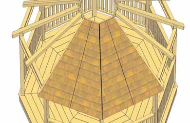
24 66. Starting at next to the entrance, lift and position 1st Left Side Roof Panel up so it sits equally between Corner and Mid Rafter. The top of the panel will sit in the dado of the Skybox frame. Panel sits in Dado of Skybox. E. Roof Section Roof Panel not to exceed top of Skybox Note, Screw locations. Position Roof Panel Section equally on Rafter. Important: After all Roof Panel Sections have been positioned and partially secured in Step 77, slight adjustments to some panels may be necessary to achieve best fit. 67. With Left Roof Panel positioned equally on rafters, secure panel to Corner Rafter and Mid Rafter on bottom row of shingles Only with 1-3 screw per side. Screw from shingles into rafters. 68. Lift and position a Right Side Roof Panel and place so equally centered on Mid and Corner Rafters. Page 24


25 Small Gap 69. Position and attach as per Step Use 2-3 screws in Corner and Mid Rafter through bottom shingle. 70. Lift and place 2nd Left Side Roof Panel in adjacent pie shape section. Small Gap 71. Position and attach as per Step Use 2-3 screws in Corner Rafter and Mid Rafter through bottom row of shingles. Lift and position 2nd Right Side Roof Panel on Center and Corner Rafter. Small Gap 72. Position and attach as per Step Use 2-3 screws in Corner and Mid Rafter through bottom row of shingles. Page 25


26 73. Complete next set of Roof Panels over entrance way. Since this will be a focal point of the gazebo, be sure to install panels carefully. Follow Steps when positioning and attaching panels. 74. Continue positioning and securing each set of Roof Panels around the Gazebo. Leave the last set of Panels towards the rear of the gazebo. 75. Complete remaining set of Roof Panels. Position and secure as per Step Page 26


27 76. After all Roof Panel Sections have been positioned and partially secured, slight adjustments to some panels may be necessary to achieve best fit. Remove previously secured bottom screws installed in Roof Panels and re-position if necessary. Important - Any gaps between Roof Panels will be covered later by Roof Ridge Caps and Filler Shingles. 77. Important - When satisfied with Roof Panel positioning, further secure panels to gazebo. Screw through Roof Panels into Corner Rafters ONLY at mid and top locations with 3 screws. See illustration above for screw pattern. Roof will be secured to Mid Rafter while securing Filler Shingles later. DO NOT SECURE ROOF TO MID RAFTERS AT THIS TIME. Reach through Skybox while securing Roof Panels at the top. Facia Board 78. Locate 64 1/2 long Facia Boards. Facia Boards are angle cut on each end. Place 1 board over the entrance way underneath the roof and against the rafter ends. Facia Board should be positioned so it is flush underneath the roof panel and angle cut end of board should sit halfway on Rafter end. Sits equally on Rafter end Page 27


28 79. With the Facia Board positioned correctly on Rafter ends, secure with 4-2 screws per side. Drill 1/8 pilot holes to prevent splitting. Note- Align screws so Facia Detail Plate will cover. See Step 128 for details. At Mid Rafter, secure Facia with 1-2 stainless screw as shown to the left. 80. Position and secure the 2nd Facia Board to end of Rafters as per Steps Important - it is normal for gaps to occur between Facia Boards. Later, Corner Facia Detail Plates will be added to cover any gaps. 81. Complete positioning and securing Facia Boards to Rafter ends. Use the same pattern as for the Roof Panel Sections. Secure as per Step 79. Important - it is normal for gaps to occur between Facia Boards. Later, Corner Facia Detail Plates will be added to cover any gaps. Page 28
.")


29 Upper Baluster bottom rail Right Side Corner Bracket 82. Locate 16 Corner Brackets (8 Left / 8 Right Side). Place into position on Post and on the Upper Baluster Section bottom rail. With Bracket Centered on Post and Upper Baluster Section, drill pilot hole in Bracket to prevent splitting before securing with 2-3 screws. 83. Complete both left and right Corner Bracket attachments making sure to position and drill pilot holes prior to securing with 3 screws. 84. Complete all Corner Bracket attachments. Important: If installing an Outdoor Living Today Optional Screen Kit. Do not install Doorway Corner Brackets. Page 29


30 F. Cupola Section Important- Pre-drilling 1/8 pilot holes in Cupola components will help prevent wood from splitting. We highly recommend this. 85. Locate 8 Side Rail Cupola Sections and place in octagon shape as shown above. 86. Screw each section together with 2-2 screws. 87. Continue attaching sections together. 88. Complete Side Rail Section and move to the side Cupola Rafter 2 from top Core Block Seat Cut in Rafter facing down 89. Locate Cupola Rafters and Core Block. Place one Rafter against Core Block as shown above. 90. Angle screw Rafter into Core Block 2 from top with 3 screw. Important - Drill 1/8 Pilot Hole in Rafter end to prevent splitting. Page 29


31 91. Continue attaching Rafters to Core Block securing with 3 screws 2 from the top. 92. Complete all Rafter / Core Block attachments. Rafter Top Straight Edge Important- angle screw up into the heart of Rafter end. Facia sits below Rafter 93. Locate 8 Cupola Facia Pieces and place against Rafter ends. 94. Position Rafter so it sits equally on both Rafter ends. Also, use a straight edge to make sure Rafter sits approx. 3/8 below rafter top. Attach Facia to Rafter end with 2-2 screws per Facia. 95. Position and secure second Facia Piece. 96. Place and secure all Facia Pieces as per Step 94. Page 31


32 97. Place completed Rafter/Facia Section on Side Rail Section. 98. Line up Rafter equally on each corner of the Side Rail Section. 99. With Rafter/Facia Section positioned equally on Side Rail Section, attach together by screwing with 1-2 screw per Rafter Locate and place 1st Cupola Roof Panel on Rafters Place Roof Panel centered equally on Rafters and against Core Block. Attach panel to rafter with 1-2 screw at top. Later In Step 105, you will completely secure Roof Panels Place 2nd Cupola Roof Panel in place. Page 32


33 103. Position and attach 2nd Cupola Roof Panel as per Step Continue to position and attach Cupola Roof Panels. Gaps may appear between Roof Panels but will be covered later by Roof Ridge Caps. 16 long 105. Position 8th Cupola Roof Panel in place and make any necessary adjustments to achieve best fit. Secure with 3 additional 2 screws per panel as per Step Locate 16 long Cupola Ridge Cap and position on corner overhanging roof by approx. 1. Secure with 2-1 1/4 shingle nails 10 from butt. Angle cut at top. 8 1/2 14 1/2 long 8 1 /2 10 1/2 long with angle cut ends Place a 14 1/2 long Cupola Ridge Cap 8 1/2 from the butt of first cap. Secure with 2-1 1/4 shingle nails 10 from butt Place a 10 1/2 angle cut end Cupola Ridge Cap over 2nd cap 8 1/2 from butt and secure with 2-1 1/4 shingle nails. Drill pilot holes to prevent splitting first. Page 33


34 109. Complete remaining Cupola corner Ridge Caps as per Steps going around in a windmill design Locate and place Top Cap / Ball Top on top of Core Block. Important- Placing Cupola on Roof requires heavy lifting. Your helper will need to be positioned on the roof. Pick Cupola up by the Side Rail Sections only Prior to attaching Top Cap / Ball Top to Core Block, drill pilot holes to prevent splitting of wood. Once complete, secure with 2-2 screws With your helper, lift completed Cupola up on top of gazebo roof. Lift Cupola from the Side Rail Sections. Skybox 113. Place Cupola so bottom of Side Rail Section sits on top of Skybox. See Step 114. for alignment With Side Rails sitting on Skybox evenly, secure with 8-3 screws from the inside. Page 34


 on roof seam slightly overhanging roof end and attach with 1")
35 115. Picture above shows illustration of completed Cupola on gazebo Next, time to install Filler Shingles to completely secure gazebo roofs and hide roof seams. Starting on bottom row of shingles, push a Long Filler Shingle (5 1/2 wide) underneath shingles directly above it until end is flush with bottom shingles. Exposure Line 1st shingle 117. With a 3 screw, secure Roof Panel down into Mid Rafter above Exposure line. Screw both left and right Roof Panels down to Mid Rafters. Make sure to screw into rafter above the exposure line to conceal screw Slide in the next long Filler Shingle and attach as per Step 117. Continue until top row. On top row, slide in Short Filler Shingle and attach with 3 screw into Mid Rafter. Important - Work around the gazebo making sure to slide in all Filler Shingles and attach Roof to Mid Rafter as per Step 117. Overhang roof by Locate all Gazebo Ridge Caps. Place 1st Ridge Cap (undercourse) on roof seam slightly overhanging roof end and attach with 1 1/4 Shingle Nails. Use less desirable looking Ridge Caps for the undercourse as it will be covered almost completely by the next Cap. Page 35


36 9 slightly recessed back Locate and place 2nd Ridge Cap on top of first cap slightly recessed back Attach 2nd Ridge Cap approx. 9 from shingle butt with 2-1 1/4 shingle nails Place 3rd Ridge Cap on roof seam Start the 3rd Ridge Cap approx 8 from bottom of 2nd Ridge cap butt. Attach with 2-1 1/4 shingles nails 9 from butt. Cut slightly smaller 124. Continue to attach Ridge Caps positioning and securing as per Steps The last Ridge Cap to complete a side must be cut shorter to fit roughly against the Cupola. Use a Utility Knife to score cap. Page 36


37 126. Attach final Ridge Cap with 2-2 screws. Complete all Ridge Caps to cover all roof seams. Facia Detail Plate 127. Locate Facia Detail Plate and place in each corner where Facia Boards come together. Detail Plates will hide any gaps that may exist between both Facia Boards. When centered in each corner of Facia, attach with 4-1 1/2 finishing nails per plate. Rim Joist Corner Detail Plates 128. Position Rim Joist Corner Detail Plates in each corner where Rim Joists come together to hid the gap. Attach with 4-1 1/2 finishing nails per plate. Page 37
38 Congratulations on assembling your 12ft Bayside Gazebo! Note: Our Gazebos are shipped as unfinished products. If exposed to the elements, the western red cedar lumber will weather to a silvery-gray color. If you prefer to keep the cedar lumber looking closer to the original color, we suggest that you treat the wood with a good oil base wood stain. You may also wish to paint your new Gazebo rather than stain it. In both cases we recommend that you consult with a paint and stain dealer in your area for their recommendations. We hope your experience assembling your 12ft Bayside Gazebo has been both positive and rewarding. We value your feedback and would like to hear back from you on how well we are doing in the following areas: 1. Customer Service 2. On Time Shipping 3. Motor Freight Delivery 4. Quality of Materials 5. Assembly Manual 6. Overall Satisfaction. Please call, write or us at: Outdoor Living Today Canadian Address th Street Maple Ridge, British Columbia Canada V2W 1L1 United States Address P.O. Box 96 Sumas, Washington USA The materials contained in this Assembly Manual may be downloaded or copied provided that ALL copies retain the copyright and any other proprietary notices contained on the materials. No material may be modified, edited or taken out of context such that its use creates a false or misleading statement or impression as to the positions, statements or actions. Toll Line: Fax: sales@outdoorlivingtoday.com Page 38
10ft Octagon Bayside Gazebo Assembly Manual
 We recommend reviewing this Assembly Manual thoroughly before starting this project. Become familiar with the tools required and where and when assistants are necessary. If you re planning on finishing
12ft Octagon (Precut) Creekside Gazebo Assembly Manual
 Creekside Gazebo Assembly Manual") 12ft Octagon (Precut) Creekside Gazebo Assembly Manual Aug 1st, 2008 Revision #9 In Florida, additional hardware may be required that is not included in kit due to hurricane winds. Please check with local
12ft Octagon (Precut) Creekside Gazebo Assembly Manual Aug 1st, 2008 Revision #9 In Florida, additional hardware may be required that is not included in kit due to hurricane winds. Please check with local
9 ft Naramata Spa Shelter Assembly Manual Outdoor Living Today
 9 ft Naramata Spa Shelter Assembly Manual Outdoor Living Today Version #8 Feb 20th, 2015 Thank you for purchasing a Naramata /Getaway Spa Shelter from Outdoor Living Today. Please take the time to identify
Screen Kit For Octagon Gazebo Assembly Manual
 Screen Kit For Octagon Gazebo Assembly Manual Revision #11 Feb 23rd/2015 Thank you for purchasing a Screen Kit for our Octagon Gazebo. Please take the time to identify all the parts prior to assembly.
6X3 Patio Garden Shed Assembly Manual
 Thank you for purchasing a 6x3 Patio Garden Shed. Please take the time to identify all the parts prior to assembly. Revision #4 July 6th, 2016 6X3 Patio Garden Shed Assembly Manual Please use Safety Eyewear
8x4 SpaceSaver Garden Shed Assembly Manual
 8x4 SpaceSaver Garden Shed Assembly Manual Revision #8 July 5, 2010 Thank you for purchasing an 8x4 SpaceSaver Garden Shed. Please take the time to identify all the parts prior to assembly. Safety Points
6x6 Maximizer Storage Shed Assembly Manual Version #9 Feb 26th, 2015
 6x6 Maximizer Storage Shed Assembly Manual Version #9 Feb 26th, 2015 Thank you for purchasing a 6x6 Maximizer Storage Shed. Please take the time to identify all the parts prior to assembly. Please Note-
Grand Garden Chalet 6X3 Assembly Manual - Costco
 Revision #16 March 22nd, 2013 Grand Garden Chalet 6X3 Assembly Manual - Costco Thank you for purchasing a Grand Garden Chalet. Please take the time to identify all the parts prior to assembly. Please use
Grand Garden Chalet 6X3 Assembly Manual
 Revision #11 June 15, 2010 Grand Garden Chalet 6X3 Assembly Manual Thank you for purchasing a Grand Garden Chalet. Please take the time to identify all the parts prior to assembly. Please use Safety Eyewear
Garden Chalet 4X2 Assembly Manual
 Revision #6 April 12th, 2010 Garden Chalet 4X2 Assembly Manual Thank you for purchasing a 4x2 Garden Chalet. Please take the time to identify all the parts prior to assembly. Please use Safety Eyewear
Grand Garden Chalet 6X3 Assembly Manual
 Revision #8 November 1, 2009 Grand Garden Chalet 6X3 Assembly Manual Thank you for purchasing a Grand Garden Chalet. Please take the time to identify all the parts prior to assembly. Please use Safety
6X3 Oscar Shed Assembly Manual
 6X3 Oscar Shed Assembly Manual Revision #7 Jan 1st, 2017 Thank you for purchasing our 6x3 Oscar Storage Shed. Please take the time to identify all the parts prior to assembly. Please use Safety Eyewear
10ft X 16ft Breeze Pergola Assembly Manual. Outdoor Living Today. Revision 6 March 20th,2012
 10ft X 16ft Breeze Pergola Assembly Manual Outdoor Living Today Revision 6 March 20th,2012 Note: Post Mounting Hardware is NOT included in this kit. Please confirm with your local building permit office
12X20 Breeze Pergola Assembly Manual Outdoor Living Today
 12X20 Breeze Pergola Assembly Manual Outdoor Living Today Revision #10 July 21th, 2015 Note: Post Mounting Hardware is NOT included in this kit. Please confirm with your local building permit office to
10X12 Arched Breeze Pergola Assembly Manual Outdoor Living Today
 10X12 Arched Breeze Pergola Assembly Manual Outdoor Living Today ITEM# BZ1012ARCH Revision 2 March 25th/2015 Note: Post Mounting Hardware is NOT included in this kit. Please confirm with your local building
Cedar Picnic Table - Model 24 Assembly Manual
 Revision #3 June 27th, 2017 Thank you for purchasing a Cedar Picnic Table. Please take the time to identify all the parts prior to assembly. Please use Safety Eye wear and Gloves while Assembling. Be sure
8X10 Breeze Pergola Assembly Manual Outdoor Living Today
 8X10 Breeze Pergola Assembly Manual Outdoor Living Today Revision #11 Jan 18th, 2018 Note: Post Mounting Hardware is NOT included in this kit. Please confirm with your local building permit office to determine
8x12 SpaceMaker Garden Shed Assembly Manual
 8x12 SpaceMaker Garden Shed Assembly Manual Version #6 Revised June / 2007 Thank you for purchasing a 8x12 SpaceMaker Garden Shed. Please take the time to identify all the parts prior to assembly. Safety
8x4 SpaceSaver Garden Shed Bevel Model Assembly Manual Revision #18 March 9th, 2017
 8x4 SpaceSaver Garden Shed Bevel Model Assembly Manual Revision #18 March 9th, 2017 Thank you for purchasing an 8x4 SpaceSaver Garden Shed. Please take the time to identify all the parts prior to assembly.
12ft X 12ft Attached Breeze Pergola Assembly Manual. Outdoor Living Today. (For Both 9 and 12 High Posts) June 1st/2012 Version #4
 June 1st/2012 Version #4") 12ft X 12ft Attached Breeze Pergola Assembly Manual (For Both 9 and 12 High Posts) Outdoor Living Today June 1st/2012 Version #4 Note: Installation of Wall Side Girders (P) and Wall Mount Brackets (M)
12ft X 12ft Attached Breeze Pergola Assembly Manual (For Both 9 and 12 High Posts) Outdoor Living Today June 1st/2012 Version #4 Note: Installation of Wall Side Girders (P) and Wall Mount Brackets (M)
12x8 Cabana Garden Shed Assembly Manual
 12x8 Cabana Garden Shed Assembly Manual Revision #15 Feb 13th, 2015 Thank you for purchasing our 12x8 Cabana Garden Shed. Please take the time to identify all the parts prior to assembly. Safety Points
9x6 Cabana Assembly Manual
 9x6 Cabana Assembly Manual Version #10 June 8, 2010 Thank you for purchasing a 9x6 Cabana. Please take the time to identify all the parts prior to assembly. Note, The General Assembly Manual illustrates
8x12 SpaceMaker Garden Shed Assembly Manual Revision #20 June 27th, 2017
 8x12 SpaceMaker Garden Shed Assembly Manual Revision #20 June 27th, 2017 Thank you for purchasing our 8x12 SpaceMaker Garden Shed. Please take the time to identify all the parts prior to assembly. Safety
8x4 SpaceSaver Garden Shed - Double Door - Bevel Model Assembly Manual Revision #18 January 3rd, 2018
 8x4 SpaceSaver Garden Shed - Double Door - Bevel Model Assembly Manual Revision #18 January 3rd, 2018 Thank you for purchasing an 8x4 SpaceSaver Garden Shed. Please take the time to identify all the parts
8x8 Spa Breeze Pergola Assembly Manual Outdoor Living Today
 8x8 Spa Breeze Pergola Assembly Manual Outdoor Living Today Revision 3. Feb 18th/2015 Note: Post Mounting Hardware is NOT included in this kit. Please confirm with your local building permit office to
9x9 Penthouse Garden Shed Assembly Manual
 9x9 Penthouse Garden Shed Assembly Manual Thank you for purchasing a 9x9 Penthouse Garden Shed. Please take the time to identify all the parts prior to assembly. Version #18 Sept. 13th, 2017 Safety Points
8x12 Santa Rosa Assembly Manual
 8x12 Santa Rosa Assembly Manual Revision #15 October 31st, 2016 Thank you for purchasing an 8x12 Santa Rosa Garden Shed from Outdoor Living Today. Please take the time to identify all the parts prior to
8x12 Santa Rosa Assembly Manual
 8x12 Santa Rosa Assembly Manual Version #10 Revised June 17, 2009 Thank you for purchasing an 8x12 Santa Rosa Garden Shed from Outdoor Living Today. Please take the time to identify all the parts prior
8x8 Sunshed Garden Shed Assembly Manual Revision #9 June 11th, 2012
 8x8 Sunshed Garden Shed Assembly Manual Revision #9 June 11th, 2012 Thank you for purchasing an 8x8 SunShed Garden Shed from Outdoor Living Today. Please take the time to identify all the parts prior to
8x8 Sunshed Garden Shed Assembly Manual
 8x8 Sunshed Garden Shed Assembly Manual Revision #13 March 16th, 2015 Thank you for purchasing an 8x8 SunShed Garden Shed from Outdoor Living Today. Please take the time to identify all the parts prior
Potting Bench Assembly Manual Outdoor Living Today
 Top Shelf Ledge (H) Potting Bench Assembly Manual Outdoor Living Today Top Shelf Back Plate (I) Revision #8 March 17th, 2015 Top Shelf End Bracket (J) Upper Shelf (D) L K Top Shelf End Bracket (J) Upper
12x12 SunShed Garden Shed
 12x12 SunShed Garden Shed Revision #9 August 21, 2010 Thank you for purchasing a 12x12 SunShed Garden Shed from Outdoor Living Today. Please take the time to identify all the parts prior to assembly. Safety
Assembly Manual. Retractable Canopy for 12X16 Breeze Pergola. Outdoor Living Today. Revision 4 May 28th/ 2012
 Assembly Manual Retractable Canopy for 12X16 Breeze Pergola Outdoor Living Today Revision 4 May 28th/ 2012 Care and Maintenance - Our canopies are designed to be maintenance free. Reasonable care to remove
12x12 SunShed Garden Shed
 12x12 SunShed Garden Shed Revision #19 September 14th, 2017 Thank you for purchasing an 12x12 SunShed Garden Shed from Outdoor Living Today. Please take the time to identify all the parts prior to assembly.
Assembly Manual. OLM Retractable Canopy for 12X16 Breeze Pergola by Outdoor Living Today. Revision #12 October 4, 2017
 Assembly Manual OLM Retractable Canopy for 12X16 Breeze Pergola by Outdoor Living Today Revision #12 October 4, 2017 Care and Maintenance - Canopy should be removed in winter to reduce the chance of collapse
8 X12 Raised Garden Bed Assembly Manual Licensed under US PATENTS 7,424,787; 7,490,435
 8 X12 Raised Garden Bed Assembly Manual Licensed under US PATENTS 7,424,787; 7,490,435 Revision #1 March 9th, 2016 Thank you for purchasing a 8 x 12 Raised Garden Bed. Please take the time to identify
10 Octagon Cedar Gazebo Assembly Instructions
 10 Octagon Cedar Gazebo Assembly Instructions Toll Free: 866.768.8465 Hours: 9-5 Monday-Friday EST www.homeplacestructures.com Package ships as shown revised 06/22/09 10 Cedar Gazebo Assembly Instructions
6 X3 Raised Garden Bed Assembly Manual
 Revision #9 pril 17th, 2017 6 X3 Raised Garden Bed ssembly Manual Thank you for purchasing a 6 x 3 Raised Garden Bed. Please take the time to identify all the parts prior to assembly. Please use Safety
Assembly Instructions
 10' and 12' Octagon Cedar Gazebo Assembly Instructions Toll Free: 866.768.8465 Hours: 9-5 Monday-Friday EST www.homeplacestructures.com Package ships as shown revised 06/20/09 Cedar Gazebo Assembly Instructions
Octagon Vinyl Gazebo Assembly Instructions For 10 & 12 Models
 Octagon Vinyl Gazebo Assembly Instructions For 10 & 12 Models Toll Free: 866.768.8465 Hours: 9-5 Monday-Friday EST www.homeplacestructures.com Package ships as shown revised 04/29/09 Vinyl Gazebo Assembly
CAUTION: Before opening the crate place it flat on its side (not up right as show in the photo) Hardware included for assembling your gazebo:
 Hardware included for assembling your gazebo:") Octagon Wood Gazebo Kit Contents Hardware included for assembling your gazebo: 5/16" Lag Bolts Use to fasten post to floor 2 1/2" screws Use to fasten joist together fasten posts to outside joist fasten
Octagon Wood Gazebo Kit Contents Hardware included for assembling your gazebo: 5/16" Lag Bolts Use to fasten post to floor 2 1/2" screws Use to fasten joist together fasten posts to outside joist fasten
Octagon Vinyl Gazebo Assembly Instructions
 Octagon Vinyl Gazebo Assembly Instructions For 10 & 12 Models Toll Free: 866.768.8465 Hours: 9-5 Monday-Friday EST www.homeplacestructures.com Package ships as shown revised 04/29/09 Vinyl Gazebo Assembly
AMISHGAZEBOSHOP.COM VINYL GAZEBO KIT CONTENTS
 VINYL GAZEBO KIT CONTENTS Hardware for assembling your gazebo (provided): 2 1/2" screws Use to fasten joist together fasten posts to outside joist fasten rafters to rafter header fasten benches & cupola
Vinyl Gazebo Instructions
 P a g e 1 Vinyl Gazebo Instructions 10 Vinyl Gazebo Shown Thank you for the purchase of your New Gazebo. Depending on the size of your Gazebo, installation can usually be completed in 1 to 2 days. These
V nyl Gazebo truct c it Assembly Instr ons
 V nyl Gazebo Vi Assembly Instr ct tr t u ru ons ct c i ti Pre-assembly Instructions A C B #1 - Site properly prepared. 4" - 6" clean stone 9 linear blocks 2" x 8" x 16" C C A A B B #1a - 12" sauna tubes,
Oval Vinyl Gazebo. Assembly Manual
 Oval Vinyl Gazebo Assembly Manual Gazebo Assembly Thank you for your purchase of this Gazebo. This manual is designed to simplify the assembly process, however we strongly recommend having an experienced
KIT ASSEMBLY INSTRUCTIONS
 KIT ASSEMBLY INSTRUCTIONS We have designed these instructions as a stepby step procedure to simplify the assembly process. Nevertheless, we do recommend including someone with carpentry expertise on your
Dodecagon Gazebo. Assembly Manual. If you are in the middle of your project and you need assistance Call (717)
") Dodecagon Gazebo Assembly Manual If you are in the middle of your project and you need assistance Call (717) 351-9250 Gazebo Assembly Manual Thank you for your purchase of this Gazebo. This manual is designed
Dodecagon Gazebo Assembly Manual If you are in the middle of your project and you need assistance Call (717) 351-9250 Gazebo Assembly Manual Thank you for your purchase of this Gazebo. This manual is designed
Octagon Greenhouse Manual
 Tools Needed: -Cordless Drill (12V or higher) -#2 Square Drive Bit -Hammer -6 Step Ladder -Tape Measure -Utility knife w/ blade & hook blade -Speed Square -5/16 Wood Drill bit Little Cottage Co. PO Box
COMPOSITE RAILING INSTALLATION
 COMPOSITE RAILING INSTALLATION Tools All you ll need is a hammer and screw gun, circular saw (carbidetipped blade with fewer than 20 teeth is recommended), level, tape measure, rasp and blue chalk line.
Sunhouse. Assembly Manual
 Sunhouse Assembly Manual Thank you for your purchase of this sunhouse. Sunhouse Assembly Manual This manual is designed to simplify the assembly process, however we recommend having an experienced carpenter
installation care & maintenance instructions lifecycledecking.com 25-year limited residential warranty 20-year limited commercial warranty
 installation care & maintenance instructions lifecycledecking.com 25-year limited residential warranty 20-year limited commercial warranty Installation Instructions As with any building project, use proper
installation care & maintenance instructions moistureshield.com limited lifetime warranty
 installation care & maintenance instructions 866.729.2378 moistureshield.com limited lifetime warranty It s comforting to know that you re about to build a deck that gives you every possible advantage.
176 S. New Holland Road Gordonville, PA Tel: Fax: Playhouse Loft
 176 S. New Holland Road Gordonville, PA 17529 Tel: 717-768-0066 Fax: 717-768-8569 A S S E M B LY M A N U A L Playhouse Loft Playhouse Loft revised 9/6/05 Assembly Manual Dear Customer, Thank you for your
Shed Assembly Instructions
 Shed Kit Contents The shed kit includes all the parts needed to assemble your shed except for tools and fasteners such as screws and nails. The various pieces are pre-cut and many are marked to indicate
ATLANTIS RAIL Contact Information
 ATLANTIS RAIL Contact Information Customer Service (800) 541-6829 (508) 732-9191 Spectrum System Installation Instructions Atlantis Rail s Spectrum System is an easy to install, universal cable railing
Renaissance Pavilion. Assembly Manual
 Renaissance Pavilion Assembly Manual Thank you for your purchase of this pavilion. Renaissance Pavilion Assembly Manual This manual is designed to simplify the assembly process, however we recommend having
Heartland Pergola. Assembly Manual
 Heartland Pergola Assembly Manual Pergola Assembly Manual Thank you for your purchase of this Pergola This manual is designed to simplify the assembly process, however we recommend having an experienced
The Festival Assembly Instructions
 The Festival Assembly Instructions Toll Free: 866.768.8465 Hours: 9-5 Monday-Friday EST www.homeplacestructures.com Package ships as shown CONTACT INFORMATION: HomePlace Structures 301 Commerce Drive New
The following instructions will guide you through the installation of your new vinyl railing stair kit.
 Installation Guide Vinyl Standard Stair Railing Tools Required Protective eye glasses Tape measure Variable speed drill/screwdriver Rotary hammer or hammer drill and masonry percussion bit recommended
Metro Series Sauna. installation instructions
 Metro Series Sauna installation instructions Please immediately check for any hidden damage that may have occurred in shipping. If any damage is found you must notify the delivering carrier within seven
Country Cabin. Assembly Manual. HomePlace Structures
 Country Cabin Assembly Manual Country Cabin Assembly Manual revised 3/20/10 Dear Customer, Thank you for your purchase of our Country Cabin. The craftsmanship and detail in this building is unmatched.
The following instructions will guide you through the installation of your new vinyl railing.
 Installation Guide St. James Vinyl T-Rail Tools Required Protective eye glasses 3/8 x 3 Concrete Anchors/Fasteners (for Tape measure concrete installations) Variable speed drill/screwdriver Philips Driver
Pacifica Pool House. Assembly Manual. Toll Free: Hours: 9-5 Monday-Friday EST. Package ships as shown. Suncast Corporation
 Pacifica Pool House Assembly Manual Toll Free: 866.768.8465 Hours: 9-5 Monday-Friday EST Package ships as shown Simpson Hurricane Straps Double Insulated Raised-Panel Door in back wall (71 x71 Total opening)
Classic Saltbox Manual
 Tools Needed: -Cordless Drill (12V or higher) -#2 Square Drive Bit -Hammer -6 Step Ladder -Tape Measure -Utility knife w/ blade & hook blade -Speed Square -5/16 Wood Drill bit Little Cottage Co. PO Box
Installation Instructions for. Before You Begin TOOLS REQUIRED
 Composite Railing System STEP-BY-STEP Installation Instructions for Spectrum Composite Railing Virtually maintenance free 20-year warranty EverNew Spectrum Railing system is designed to work with a number
IMPORTANT!!! ASSEMBLY ASSEMBLY INSTRUCTIONS. (Internal Dimensions)
") ASSEMBLY ASSEMBLY INSTRUCTIONS (Internal Dimensions) Ent Spec Edition Ltr v-0- Overall dimensions including base: 7. L x 9 W x 0 H cms 97.5" L x 7" W x 8.7" H IMPORTANT!!! Please read these instructions
ASSEMBLY ASSEMBLY INSTRUCTIONS (Internal Dimensions) Ent Spec Edition Ltr v-0- Overall dimensions including base: 7. L x 9 W x 0 H cms 97.5" L x 7" W x 8.7" H IMPORTANT!!! Please read these instructions
Gambrel Barn with Overhang Manual
 Tools Needed: -Cordless Drill (12V or higher) -#2 Square Drive Bit -Hammer -6 Step Ladder -Tape Measure -Square utility knife w/ blade & hook blade -Speed Square Little Cottage Co. PO Box 455 Berlin, OH
PATIO INSTALLATION MANUAL
 PATIO INSTALLATION MANUAL A few minutes spent reviewing the following instructions will help insure quick and proper assembly. The Patio Sauna Kit will arrive on a stretchwrapped pallet including pre-built
Best Barns USA. the Brookhaven 10' x 16' Assembly Book. revised March 23, 2016
 Best Barns USA Assembly Book revised March 23, 2016 the Brookhaven 10' x 16' Manufactured by Reynolds Building Systems, Inc. 205 Arlington Drive Greenville, PA 16125 724-646-3775 This manual is copyrighted.
176 S. New Holland Road Gordonville, PA Tel: Fax: Castle Loft
 176 S. New Holland Road Gordonville, PA 17529 Tel: 717-768-0066 Fax: 717-768-8569 A S S E M B LY M A N U A L Castle Loft Castle Loft Assembly Manual revised 08/31/05 Dear Customer, Thank you for your purchase
INSTALLING INVISIRAIL GLASS PANELS POST INFORMATION... 2 PRE-INSTALLATION... 2
 Contents POST INFORMATION... 2 PRE-INSTALLATION... 2 STEP A1: MEASURING FOR INVISIRAIL CUSTOM GLASS PANELS (skip if using Standard Sized Panels)... 2 STEP A2: GATHER ADDITIONAL TOOLS/SUPPLIES... 2 STEP
Best Barns USA Assembly Book
 Best Barns USA Assembly Book Revised September 19, 2017 the Millcreek 12'x 20' Manufactured by Reynolds Building Systems, Inc 205 Arlington Drive Greenville, PA 16125 This manual is copyrighted Under the
INS A KSCR INSTALLATION INSTRUCTIONS STANDARD PROCEDURE. 1. Unpacking the KSCR Splicing the KSCR (If Required)...
...") INS-88.500-0A KSCR INSTALLATION INSTRUCTIONS STANDARD PROCEDURE 1. Unpacking the KSCR... 2 2. Splicing the KSCR (If Required)... 4 3. Assemble Curb and Rail Corners... 5 4. Install Cross Bracing (If Required)...
INS-88.500-0A KSCR INSTALLATION INSTRUCTIONS STANDARD PROCEDURE 1. Unpacking the KSCR... 2 2. Splicing the KSCR (If Required)... 4 3. Assemble Curb and Rail Corners... 5 4. Install Cross Bracing (If Required)...
Frameless Inline Door With Return QCI5263
 INSTALLATION INSTRUCTIONS Frameless Inline Door With Return QCI5263 WALL MOUNT HINGES FRAMELESS DOOR / PANEL / RETURN PANEL QCI5263 REV. 0 Page 1 Certified 06/17/2016 Parts List with wall mount hinges
10, 12 &14 Oval Gazebo Floor
 0, 12 &14 Oval Gazebo Floor Revision: 2-26-03 Run: - BEFORE YOU BEGIN - Always wear OSHA-APPROVED safety glasses throughout assembly process First... Read these instructions thoroughly before you begin
TREX TRANSCEND RAILING
 RAILING NOTES:» RAILINGS ARE DESIGNED TO BE INSTALLED OVER THE DECKING FRAME OR ON INSIDE OF RIM JOIST. NOTCHING OF PRESSURE-TREATED POSTS OR POSTS INSTALLED ON OUTSIDE OF RIM JOIST IS NOT ALLOWED.» All
VINYL CLASSIC FREESTANDING PERGOLA ASSEMBLY INSTRUCTIONS
 P a g e 1 VINYL CLASSIC FREESTANDING PERGOLA ASSEMBLY INSTRUCTIONS Shown: 8' x 12' Vinyl Classic Pergola with 12" Top and Main Runner Spacing The design of this pergola is based on all posts being installed
TREX ENHANCE RAILING (Also Applies to Trex Select Railing) Installation Instructions
 Installation Instructions") TREX ENHANCE RAILING (Also Applies to Trex Select Railing) NOTE: All Enhance Railing lengths are manufactured at CLEAR SPAN dimensions (spanning between space of posts): 7" for 6' clear span. Note that
TREX ENHANCE RAILING (Also Applies to Trex Select Railing) NOTE: All Enhance Railing lengths are manufactured at CLEAR SPAN dimensions (spanning between space of posts): 7" for 6' clear span. Note that
AFCO-Rail Post INSTALLATION INSTRUCTIONS AFCO-RAIL POST
 AFCO-Rail Post INSTALLATION INSTRUCTIONS TOOLS REQUIRED: Drill Bits (for the appropriate fastener) Drill (with adjustable clutch, recommended) Level String Line Tape Measure Tools to install fasteners
Corner Potting Store Assembly Instructions
 Corner Potting Store Assembly Instructions English SS225E Before assembly We recommend that time is taken to read the instructions before starting assembly, then follow the easy step by step guide. The
Best Barns USA. Assembly Book. 12'x 16' the Millcreek. Revised September 19, 2017
 Assembly Book Best Barns USA Revised September 19, 2017 the Millcreek 12'x 16' Manufactured by Reynolds Building Systems, Inc 205 Arlington Drive Greenville, PA 16125 This manual is copyrighted Under the
Potting Store Assembly Instructions
 Before assembly We recommend that time is taken to read the instructions before starting assembly, then follow the easy step by step guide. The instruction sheet is only a guide to the assembly. Certain
Monterey. 10,12 and 14 Oval Gazebo Instructions
 1000 Ternes Drive Monroe, MI 48162 Toll Free 1-800-437-0784 - BEFORE YOU BEGIN - Always wear OSHA-APPROVED safety glasses throughout assembly process First... Read these instructions thoroughly before
Mt. BLANC INSTRUCTIONS TOLL FREE: Mt_Blanc_11x11_Instructions_V1.0 EN " " " " " " "
 INSTRUCTIONS 142 5 16" 128 1 2" I-FOLD AR WINDOW 82 3 8" 112 3 4" I-FOLD WINDOW 122 3 4" 152 1 2" I-FOLD WINDOW 149 1 2" Mt_lanc_11x11_Instructions_V1.0 EN IMPORTANT TOOLS NEEDED EFORE YOU EGIN POWER
CXT PRO RAILING INSTALLATION INSTRUCTIONS For Installations Using Aluminum and Glass Balusters Sold Separately
 CXT PRO RAILING INSTALLATION INSTRUCTIONS For Installations Using Aluminum and Glass Balusters Sold Separately CCRR-0171 PFS AA-652 Drill/power screwdriver Assorted drill bits Hammer Miter or circular
Gambrel Barn Construction Manual 8x8 through 16x24 Units
 Gambrel Barn Construction Manual 8x8 through 16x24 Units Tools Needed: Cordless drill (12V or higher) #2 square drive bit Hammer 6 step ladder Tape measure Square utility knife w/ blade & hook blade Little
12, 14 & 16 Wide Enclosure Assembly Guide
 www.rmfiberglass.com 12, 14 & 16 Wide Enclosure Assembly Guide RM Products Ltd 1-800-363-0867 www.rmfiberglass.com Table of Contents 1. Handling and Storage page 3 to 5 2. Parts and Tools List page 7 3.
Boxed Shed. QUAKER or A-FRAME SIZES: 6 x 8 6 x 10 T1-11Siding
 Boxed Shed QUAKER or A-FRAME SIZES: 6 x 8 6 x 10 T1-11Siding Required Equipment; * Power Drill with square head bit * Hammer, Square, Gloves & an Allen wrench * Step Ladder Screws Supplied; * 2 for roof
Sliding Door Kit
 YOU MUST READ THIS DOCUMENT BEFORE YOU BEGIN TO ASSEMBLE THE DOOR KIT. Thank you for purchasing this GrowSpan door kit. When properly assembled and maintained, this product will provide years of reliable
Mt. SUTTON INSTRUCTIONS TOLL FREE: _Mt_Sutton_12x12_Instructions_V1.2 EN [3790mm] [3467mm] [3874mm]
![Mt. SUTTON INSTRUCTIONS TOLL FREE: _Mt_Sutton_12x12_Instructions_V1.2 EN [3790mm] [3467mm] [3874mm]](/thumbs/91/107166081.jpg "Mt. SUTTON INSTRUCTIONS TOLL FREE: _Mt_Sutton_12x12_Instructions_V1.2 EN [3790mm] [3467mm] [3874mm]") 82 3 8 [2093mm] 113 15 16 [2893mm] I-FOLD AR WINDOW I-FOLD WINDOW 28 7 8 18 1 16 136 1 2 [3467mm] DOULE DOOR I-FOLD WINDOW 42 5 8 18 1 16 28 7 8 149 3 16 [3790mm] 136 1 2 [3467mm] I-FOLD AR WINDOW 17 7
82 3 8 [2093mm] 113 15 16 [2893mm] I-FOLD AR WINDOW I-FOLD WINDOW 28 7 8 18 1 16 136 1 2 [3467mm] DOULE DOOR I-FOLD WINDOW 42 5 8 18 1 16 28 7 8 149 3 16 [3790mm] 136 1 2 [3467mm] I-FOLD AR WINDOW 17 7
Dura-Lock Roof System
 DLR-14 Dura-Lock Roof System Assembly and Installation Instructions Read the instructions before starting the job. They explain the steps required to produce a finished product that will meet factory specifications.
Stair Parts Installation. Tricks
 Stair Parts Installation Tips & Tricks Introduction Your DIY staircase guide Welcome to the Stairpart home installation guide. Your stairway is both a functional and focal point in your home, so keeping
TREX SELECT RAILING Installation Instructions
 RAILING NOTE : All Trex Select Railing lengths are manufactured at ON CENTER dimensions (spanning from center of each post): 67-5/8" (76.8 cm) for 6' (.83 m) on center, and 9-5/8" (35.3 cm) for 8' (.44
Oriental Pagoda Assembly Instructions
 Oriental Pagoda Assembly Instructions English SS136A Before assembly We recommend that time is taken to read the instructions before starting assembly, then follow the easy step by step guide. The instruction
Assembly Instructions for 12x16 Floating Dock
 Assembly Instructions for 12x16 Floating Dock www.rollingbarge.com Congratulations on the purchase of your Floating Dock kit. This kit includes all the aluminum frame parts, and all the fasteners. You
Assembly Instructions 10 X 10 Aluminum Roof Support
 Assembly Instructions 10 X 10 Aluminum Roof Support Aluminum Roof Support Bolt Package 16-5/16 X 2 ¼ SS Bolt 24-5/16 X 1 SS Bolt 40-5/16 SS Nylon Lock Nuts 16-5/16 SS Flat Washers 28-4 ½ Wood Screws 36-1
THANK YOU FOR PURCHASING FROM HERITAGE PATIOS
 Installation Guide THANK YOU FOR PURCHASING FROM HERITAGE PATIOS Your purchase is engineered by nearly a half century of commercial and residential product design proudly manufactured in the USA from responsibly
Best Barns USA Assembly Book
 Best Barns USA Assembly Book Revised August 17, 2017 the Roanoke 16'x32' Building w/ full loft Manufactured by Reynolds Building Systems, Inc 205 Arlington Drive Greenville, PA 16125 This manual is copyrighted
Cape Cod Manual. Little Cottage Co. PO Box 455 Berlin, OH Little Cottage Co.
 Tools Needed: -Cordless Drill (12v or higher) -#2 Square drive bit -Hammer -6 Step Ladder -Tape Measure -Square utility knife with blade & hook blade -Speed Square Little Cottage Co. PO Box 455 Berlin,