AWNING SYSTEM INSTALLATION INSTRUCTIONS ALL VERTICAL WALLS
|
|
|
- Adam McDaniel
- 5 years ago
- Views:
Transcription


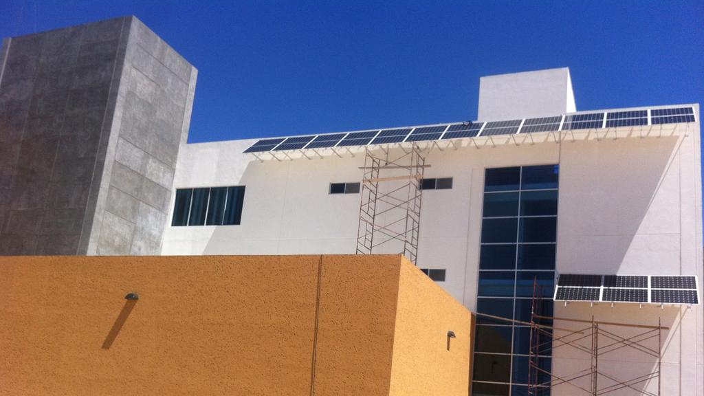
1 INSTALLATION MANUAL AWNING SYSTEM INSTALLATION INSTRUCTIONS ALL VERTICAL WALLS
2
3 TABLE OF CONTENTS Table of Contents... 3 Components... 4 System Components... 6 Attachment Components... 7 Module Compatibility... 8 System Layout... 9 SYSTEM LAYOUT - PORTRAIT SYSTEM LAYOUT - LANDSCAPE Pre-Job Layout Preparations Wall Mounts Horizontal Leg Angle Adapter Angled Frame To L-Foot Angled Frame To Adapter Cross Connectors Bracing Cross Rails Fixed Rail Connector Flexible Rail Connector Microinverter End Clamp & First Module Mid Clamp & Module Cutting Access Rail End Cap Grounding Lug Jumper Wire at Flexible Rail Connector Locations Wire Management Clip Appendix TABLE OF CONTENTS Table of Contents 3 / 35
4 PRE-JOB LAYOUT PREPARATIONS COMPLETE A SITE SURVEY 1. Obtain a set of roof plans or draw your own. 2. Verify that all dimensions are correct. 3. Note locations of roof penetrations (chimneys, vents, etc.) 4. Note the roof construction materials and locate framing member locations, paying attention to the spacing of the framing members. 5. Assess objects creating shading concerns DETERMINE THE SOLAR LAYOUT 1. It is recommended that your design be approved by a local building authority before beginning installation. Typically the rail span between supporting roof anchors is the most important design consideration. A solar checklist form and web resources are available at Solar checklist information must be provided along with jobsite information (preferably a roof plan) in order to provide the free solar array layout. For more details contact TRA Snow and Sun. 2. The solar layout should be designed with the following factors in mind that affect the structural design of the solar array: Windspeed Building height Snow load Exposure category Importance factor Roof slope/pitch 3. Other factors to be considered: Sun exposure Objects causing shading Proximity to inverters/electrical panels String capacities, etc. 4. Some local jurisdictions fire codes require walkways or edge clearances. Pre-Job Layout Preparations 4 / 35
5 COMPONENTS Components 5 / 35


6 ROOF ATTACHMENTS COMPONENTS L-FOOT L-FOOT A MODULE CLAMPS RAIL CONNECTORS MID CLAMP ASSEMBLY 15101XXX END CLAMP ASSEMBLY 15102XXX CROSS CONNECTOR FIXED FLEX CONNECTOR 740XXXXX THIN FILM MID CLAMP ASSEMBLY 72203XXX THIN FILM END CLAMP ASSEMBLY 72203XXX Components 6 / 35


7 ACCESSORIES RAIL END CAP WIRE MANAGEMENT CLIP 72215XXX SOLAR RAIL PLUS 7403XXXX INSTALLATION COMPONENTS MANUALS WEEB LUG 8.0 WEEB-LUG WEEB-SMC 2 WEEB-SMC FASTENERS M8 FLANGE LOCK NUT SLIDING BLOCK SDS SCREW SDSS101 SOCKET HEAD CAP SCREW *Actual Size Components 7 / 35

8 SYSTEM COMPONENTS 5 SYSTEM COMPONENTS SOLAR RAIL PLUS: Supports PV modules and accessories. Available in lengths up to Extruded aluminum. Available in mill finish or black anodized. 2 CROSS CONNECTOR: Supports cross braced mounting systems. Aluminum mill finish or black anodized. 3 FLEXIBLE RAIL CONNECTOR: Joins and aligns rail sections allowing for expansion due to natural temperature variation. Installed every 50 of Solar Rail Plus. Mill finish aluminum. (Non-bonded) 4 FIXED RAIL CONNECTOR: Joins, aligns, and electrically bonds rail sections into single length of rail. Available in mill finish or black anodized. 5 END CLAMP ASSEMBLY: Includes End Clamp, Solar Grounding Clip, and M8 Socket Head Cap Screw 6 MID CLAMP ASSEMBLY: Includes Mid Clamp, Solar Grounding Clip, M8 Socket Head Cap Screw 7 END CLAMP: Pre-assembled End Clamp with Solar Grounding Clip (SGC) provides module to rail bond. End Clamp available in mill finish and black anodized. 8 MID CLAMP: Pre-assembled Mid Clamp with Solar Grounding Clip (SGC) provides module to module and module to rail bond. Mid Clamp available in mill finish and black anodized. 9 ROLL IN BLOCK: Easily clips into place in the top channel of the Solar Rail Plusl for easy Mid/End Clamp placement. Provides electrical bond between Mid Clamp or End Clamp to the rail. Mill finish aluminum. 10 L-FOOT: Secures rails to wall. Mill finish aluminum. 11 M8 SOCKET HEAD CAP SCREW: Use when securing components to the Solar Rail Plus in conjunction with the Sliding Block or Solar Grounding Clip. Stainless Steel. 12 END CAPS: Provide a clean, finished appearance on ends of Solar Rail Plus concealing any rough edges. Polypropylene End Cap available in grey or black. 13 GROUNDING LUG (WEEB LUG 8.0): Used to ground the Solar Rail Plus to a copper ground wire. Includes a stainless steel washer and a tin-plated copper lug. 14 SLIDING BLOCK: Provides threaded connection point to Solar Rail Plus. Rolls and slides into place in channels of Solar Rail Plus. Mill finish aluminum. 15 ANGLE ADAPTER: Used to connect two pieces of rail at an angle to join the tilted portion of the structure. System Components 8 / 35
 AWNING")


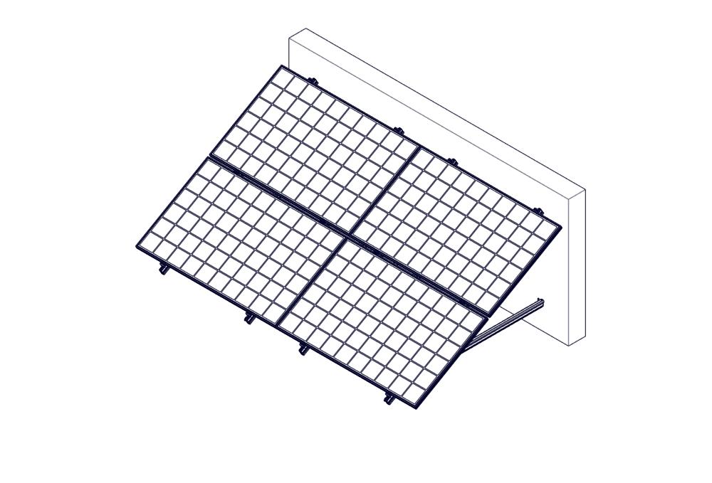
9 AWNING LANDSCAPE (OPTION A) AWNING PORTRAIT (OPTION B) ATTACHMENT INSTALLATION COMPONENTS MANUALS Attachment Components 9 / 35

10 MODULE COMPATIBILITY INSTALLATION MANUALS MODULE COMPATIBILITY Height Varies or SOLAR RAIL PLUS The heights of the End Clamp Assembly and Mid Clamp Assembly varies and are dependant on the solar module frame thickness. TRA Snow and Sun can customize End Clamps to fit any solar module. Module Compatibility 10 / 35
11 TRA Snow and Sun will provide an engineered layout for all Awning Mount Systems we design. An engineered plan will specify the spacing requirements per the project design criteria. As a standard, we design the Solar Rail Plus to be installed parallel or perpendicular to the rafters/trusses. Custom designs are available. Supporting wall attachments are required to be spaced, depending on local building requirements. The installer should check with the local building department to make sure the project complies with the specific code requirements for their locality. Customer is required to provide and verify that all design criteria is correct. AWNING LANDSCAPE (OPTION A) SYSTEM LAYOUT - LANDSCAPE TRA Snow and Sun s Landscape layout is installed with the mounting rails perpendicular to the wall. All wall attachments are mounted so flashing can be added to create a waterproof seal. Supporting wall attachments are required to be spaced, using either cross connectors or cross rails depending on local building requirements. The installer should check with the local building department to make sure the project complies with the specific code requirements for their locality. SYSTEM LAYOUT AWNING PORTRAIT (OPTION B) SYSTEM LAYOUT - PORTRAIT TRA Snow and Sun s portrait layout is installed with the mounting rails parallel to the wall. All wall attachments are mounted so flashing can be added to create a waterproof seal. Supporting roof attachments are required to be spaced, using either cross connectors or cross rails depending on local building requirements. The installer should check with the local building department to make sure the project complies with the specific code requirements for their locality. NOTES: Mid Clamp Assembly requires a ¾ inch gap between modules. TRA recommends 2 of Solar Rail Plus protruding at the ends of any string of panels for End Clamps and/or Grounding Lugs. Maximum rail span cannot exceed 6. The distance between roof attachments should be 6 apart or less. System Layout 11 / 35
12 PRE-JOB LAYOUT PREPARATIONS COMPLETE A SITE SURVEY 1. Obtain a set of roof plans or draw your own. 2. Verify that all dimensions are correct. 3. Note locations of roof penetrations (chimneys, vents, etc.) 4. Note the roof construction materials and locate framing member locations, paying attention to the spacing of the framing members. 5. Assess objects creating shading concerns DETERMINE THE SOLAR LAYOUT 1. It is recommended that your design be approved by a local building authority before beginning installation. Typically the rail span between supporting roof anchors is the most important design consideration. A solar checklist form and web resources are available at Solar checklist information must be provided along with jobsite information (preferably a roof plan) in order to provide the free solar array layout. For more details contact TRA Snow and Sun. 2. The solar layout should be designed with the following factors in mind that affect the structural design of the solar array: Windspeed Building height Snow load Exposure category Importance factor Roof slope/pitch 3. Other factors to be considered: Sun exposure Objects causing shading Proximity to inverters/electrical panels String capacities, etc. 4. Some local jurisdictions fire codes require walkways or edge clearances. Pre-Job Layout Preparations 12 / 35


13 Brick Step 1 WALL MOUNTS The Awning Solar Mounting Frame can be mounted on any wall type (concrete, frames, metal, brick, etc.). The fasteners are to be determined by the custpmer based on the material strength of the wall or wall framing material. MARK FRAME LOCATIONS TO PREPARE THE ROOF 1. Determine the location for the Frames on the vertical wall structure. (Refer to information gathered in the site survey and module manufacturer recommendations.) WALL MOUNTS 2. Mark the location using a chalk line to ensure a plum installation. Mark a horizontal line in the locations the Awning Frame is to be installed. 3. Layout Awning Frames at chalk line locations. 4. Mount the L-Base Brackets to the wall with customer determined fastener. 5. Spacing & locations is dtermined by TRA s Engineered Layout. Concrete NOTES: Spacing varies based on the size of the solar panel, wall framing spacing and the desired mounting angle of the system. Please refer to system drawings provided by TRA Snow and Sun for the correct spacing for your wall mounts. Studs Wall Mounts 13 / 35

14 Step 2 HORIZONTAL LEG HORIZONTAL LEG 1. Attach the Rails to the roof mount by first seating the Sliding Block into the Rail side channel in proximity to the mounting location by rolling it into the channel. 2. Set the rail into position with side channel flush against the uphill face of the attachment. Adjust Sliding Blocks by sliding them into alignment with the slotted hole. (If a Flexible Connector is needed insert it before adding additional rails.) 3. Insert the Socket Head Cap Screw through the roof attachment into the Sliding Block that is positioned inside the side channel of the Rail and torque to 12 ft-lbs. NOTES: The L-Foot requres a M8 X 16mm Socket Head Cap Screw. Rail is installed with the top channel facing the ground. Make sure rail is horizontal. Horizontal Leg 14 / 35

15 Step 3 ANGLE ADAPTER FRAME LAYOUT 1. Attach the Angle Adapter to the Solar Rail Plus by first setting the Sliding Block into the Solar Rail Plus side channel in proximity to the mounting location by rolling it into the channel. ANGLE ADAPTER 2. Hand tighten M8 x 16mm Socket Head Cap Screw until after step 6 is completed. Angle Adapter 15 / 35
16 ANGLED FRAME TO L-FOOT Step 4 ANGLED FRAME TO L-FOOT 1. Attach the Rails to the roof mount by first seating the Sliding Block into the Rail side channel in proximity to the mounting location by rolling it into the channel. 2. Set the rail into position with side channel flush against the uphill face of the attachment. Adjust Sliding Blocks by sliding them into alignment with the slotted hole. (If a Flexible Connector is needed insert it before adding additional rails.) 3. Insert the Socket Head Cap Screw through the roof attachment into the Sliding Block that is positioned inside the side channel of the Rail and torque to 12 ft-lbs. NOTES: The L-Foot requres a M8 X 16mm Socket Head Cap Screw. Rail is installed with the top channel facing the ground. Make sure rail is horizontal. Angled Frame To L-Foot 16 / 35

17 Step 5 ANGLED FRAME TO ADAPTER 1. Attach the Angle Adapter to the Solar Rail Plus by first setting the Sliding Block into the Solar Rail Plus side channel in proximity to the mounting location by rolling it into the channel. 2. Torque M8 x 20mm Socket Head Cap Screw to 12 ft-lbs. ANGLED INSTALLATION FRAME TO MANUALS ADAPTER 3. Torque all Socket Head Cap Screws from STEPS 4-5 to 12 ft.-lbs. Angled Frame To Adapter 17 / 35
 M8 x 16mm Socket Head Cap Screw and (5) M8 flange lock nuts. 2. If multiple columns of frames the back bracing can be staggered.")
18 Step 6 CROSS CONNECTORS CROSS CONNECTORS 1. If (1) one column of frames the back bracing needs to be crossed. Attach Back Brace by using (5) M8 x 16mm Socket Head Cap Screw and (5) M8 flange lock nuts. 2. If multiple columns of frames the back bracing can be staggered. Attach Back Brace by using (2) M8 x 16mm Socket Head Cap Screw and (2) M8 flange lock nut. Where the Back Bracings overlap (1) M8 x 16mm Socket Head Screw and (1) M8 flange lock nut will not be needed. 3. Torque all connections to 15 ft. -lbs. 4. Repeat Steps 1-2 for all Backing using the engineered layout drawing as a guide. Cross Connectors 18 / 35
 M8 x 16mm Socket Head Cap Screw and (5) M8 flange lock nuts. 2. If multiple columns of frames the back bracing can be staggered.")
 M8 x 16mm Socket Head Screw and (1) M8 flange lock nut will not be needed. INSTALLATION BRACING MANUALS 3. Torque all connections to 15 ft. -lbs. 4.")
19 ZIGZAG PATTERN - OPTION 1 Step 7 BRACING 1. If (1) one column of frames the back bracing needs to be crossed. Attach Back Brace by using (5) M8 x 16mm Socket Head Cap Screw and (5) M8 flange lock nuts. 2. If multiple columns of frames the back bracing can be staggered. Attach Back Brace by using (2) M8 x 16mm Socket Head Cap Screw and (2) M8 flange lock nut. Where the Back Bracings overlap (1) M8 x 16mm Socket Head Screw and (1) M8 flange lock nut will not be needed. INSTALLATION BRACING MANUALS 3. Torque all connections to 15 ft. -lbs. 4. Repeat Steps 1-2 for all Backing using the engineered layout drawing as a guide. CROSS PATTERN - OPTION 2 NOTES: The braces should be between two panels to tie the system together, not under a single panel. Bracing 19 / 35

20 Step 8 CROSS RAILS - PORTAIT OPTION B For landscape module layouts using cross rails, add additional rails perpendicular to previously mounted rails to support modules. CROSS RAILS 1. Attach the Cross Connector to the Solar Rail Plus by first seating the Sliding Block into the Solar Rail Plus top channel in proximity to the mounting location by rolling it into the channel. Torque M8 X 16 Socket Head Cap Screw to 12 ft-lbs. (This will be done on the horizontal Solar Rail Plus previously installed.) 2. Attach the Cross Connector to the Solar Rail Plus by first seating the Sliding Block into the Solar Rail Plus side channel in proximity to the mounting location by rolling it into the channel. 3. Set the rail into position with side channel flush against the vertical face of the Cross Connector and Weeb-SMC-2. Adjust Sliding Blocks by sliding them into alignment with the Cross Connector mounting hole. 4. Insert the M8 X 16 Socket Head Cap Screw through the Cross Connector and Weeb-SMC-2 then into the Sliding Block that is positioned inside the side channel of the Solar Rail Plus and torque to 12 ftlbs. NOTES: A Weeb-SMC-2 is required for connections between the Cross Connector and the Solar Rail Plus. Cross Connector is not symetrical. A M8X16 Socket Head Cap Screw is used on the thin side and an M8 X 20 Socket Head Cap Screw is used on the larger side. Cross Rails 20 / 35
 rail ends next to each other and snap the Fixed Rail Connector in place and fasten with (2) self tapping screws into the side of the")
21 Step 9 FIXED RAIL CONNECTOR - PORTAIT OPTION B 1. Align the two (2) rail ends next to each other and snap the Fixed Rail Connector in place and fasten with (2) self tapping screws into the side of the Solar Rail Plus. 2. Torque all connections to 12 ft. -lbs. FIXED RAIL CONNECTOR Fixed Rail Connector 21 / 35
22 FLEXIBLE RAIL CONNECTOR Step 10 FLEXIBLE RAIL CONNECTOR - OPTION B 1. Align the two (2) rail ends next to each other and snap the Fixed Rail Connector in place and fasten with (1) self tapping screws into the side of the Solar Rail Plus. 2. Torque all connections to 12 ft. -lbs. 3. Do not push rails tight together. Leave a 2 gap to allow for expansion. Flexible Rail Connector 22 / 35

23 Step 11 MICROINVERTER One microinverter must be installed for each module. 1. Insert Sliding Block into the top channel of the Solar Rail Plus. 2. Using an M8 X 10mm Socket Head Cap Screw attach the microinverter. INSTALLATION MICROINVERTER MANUALS 3. Torque to 12 ft-lbs. 4. Repeat for each microinverter. NOTES: For additional options to mount microinverters, contact TRA Snow and Sun. Inverter bonding was not tested by UL. Microinverter 23 / 35


24 END CLAMP AND FIRST MODULE STEP 12 END CLAMP AND FIRST MODULE End Clamps are used on the first and last modules of a string or array to secure the edge of the module to the Solar Rail Plus. For easy installation the End Clamp Assembly is installed as a pre-assembled component with a Socket Head Cap Screw fastened through the End Clamp and into the Roll In Block. 1. Roll the End Clamp Assembly into the top channel on the Solar Rail Plus and slide it into place. 2. Slide the module into place and loosely secure the End Clamp Assembly. 3. Repeat at the ends of each rail. 4. Align modules into place then tighten the End Clamp Assembly and torque to 15 ft. -lbs. NOTES: The height of the End Clamp Assembly vary and are dependent on the solar module frame thickness. (Works for both regular and Glass Clamps) End Clamp and First Module 24 / 35

25 INSTALLATION MANUALS STEP 13 MID CLAMP AND MODULE Mid Clamps are used to secure two modules to the Solar Rail Plus. For easy installation the End Clamp Assembly is installed as a pre-assembled component with a Socket Head Cap Screw fastened through the End Clamp and into the Roll In Block. 1. Roll the Mid Clamp Assembly into the top channel on the Solar Rail Plus and slide it into place. 2. Slide the module into place and loosely secure the Mid Clamp Assembly. MID CLAMP AND MODULE 3. Repeat for each subsequent module. 4. Align modules into place then tighten the Mid Clamp Assembly and torque to 15 ft. -lbs. (Works for both regular and Glass Clamps) NOTES: The height of the End Clamp Assembly vary and are dependent on the solar module frame thickness. Mid Clamp and Module 25 / 35
 from the module the")
26 STEP 14 CUTTING ACCESS RAIL CUTTING ACCESS RAIL 1. If the Solar Rail Plus extends out beyond the required distance (2 ) from the module the excess may be cut off. Cutting Access Rail 26 / 35

27 STEP 15 END CAP 1. To install the End Cap, align the pegs of the End Cap with the corresponding locations in the rail profile and press in. The End Cap may also be gently tapped with a hammer or similar instrument. It must be completely seated into the end of the Solar Rail Plus to ensure effectiveness. END CAP Continue to STEP 16 on page 26 - GROUNDING LUG. End Cap 27 / 35


28 STEP 16 GROUNDING LUG A Grounding Lug must be installed at the end of each run of modules on the end of the Solar Rail Plus. GROUNDING LUG 1. Insert Sliding Block into the top channel of the Solar Rail Plus. 2. Using an M8 X 16mm Socket Head Cap Screw attach the Grounding Lug and Lug Washer. 3. Torque to 12 ft. -lbs. 4. Repeat for each end of rail. NOTES: Grounding Lug must be attached at 60 in-lbs to 6-14 AWG solid/strand copper wire. Grounding Lug 28 / 35
 Solar Rail Plus runs together. 1. Slide Sliding Blocks into side channel of both rails near the Flexible Rail Connector (not always needed). 2.")
29 STEP 17 JUMPER WIRE AT FLEXIBLE RAIL CONNECTOR LOCATIONS For Solar Rail Plus lengths exceeding 50 a Flexible Rail Connector is required, Grounding Lugs must be installed on both sides and a jumper wire used to tie the two (2) Solar Rail Plus runs together. 1. Slide Sliding Blocks into side channel of both rails near the Flexible Rail Connector (not always needed). 2. Align and install (2) Grounding Lugs. JUMPER WIRE AT FLEXIBLE RAIL CONNECTOR 3. Attach the (10) gauge solid copper wire to both lugs. 4. Droop the wire to allow for expansion. NOTES: Grounding Lug must be attached at 60 in-lbs to 6-14 AWG solid/strand copper wire. Jumper Wire At Flexible Rail Connector 29 / 35


30 STEP 18 WIRE MANAGEMENT CLIP WIRE MANAGEMENT CLIP 1. To install the Wire Management Clip, align the bottom U on rail wire management channel and clip to channel of Solar Rail Plus and snap into place. 2. Continue placing Wire Management clip where is necessary. Wire Management Clip 30 / 35
31 APPENDIX MAINTENANCE Perform a visual inspection annually to ensure there is no damage to mounting hardware. Complete inspection bi-annually to ensure there are no loose fasteners, connection points, to ensure proper grounding and that the system will withstand any inclement weather. All components to be single use only for bonding. MODULES TESTED WITH THIS RACKING SYSTEM Solar World: SunModule Plus SW 270 mono, SunModule Plus SW 275 mono, SunModule Plus SW 280 mono APPENDIX Canadian Solar: CS6P-250w, CS6P-255w, CS6P-260w, CS6X-300w, CS6X-305w, CS6X-310w Sunpreme Modules: Maxima GxB 300 SL Bifacial Module Note: Other modules are compatible with the Flush Mount System. To have UL Certification with the Flush Mount System the listed modules are required. FIRE RATING FUSE RATING This system has been tested to a max fuse rating of 25 Amps. MISSION STATEMENT TRA Snow and Sun s Mission is to offer the highest quality snow retention, solar mounting systems, flexible roof flashing and ventilation products made from superior materials that provide the ultimate in protection, durability and dependability. We strive daily to provide customized service, exceptional engineering, superior manufacturing, and resourceful solutions for each customer, focusing on the unique requirements of each project. Our team is united, innovative and dedicated. Each employee pursues excellence in each company endeavor and realizes that maintaining the good reputation that took decades to establish depends on them. We are not content to simply be successful, but strive to set new and higher standards in all that we do. Appendix 31 / 35
32
33


34 At TRA Snow and Sun we engineer and layout each project upon request free of charge. Just give us the project details and we will give you the rail spans, max loads on components, wind parameters, solar panel geometry, force per foot on rail and panels, a schematic of the module field, the wind speed, shipping weight, and project details. CONTACT US TRA SNOW AND SUN info@trasnowandsun.com
Installation Manual FLUSH MOUNT - Shingle, Slate,etc. Questions? Call Us! +1 (800)
") www.trasnowandsun.com S Installation Manual FLUSH MOUNT - Shingle, Slate,etc. At TRA Snow and Sun we engineer and layout each project upon request free of charge. Just give us the project details and we
www.trasnowandsun.com S Installation Manual FLUSH MOUNT - Shingle, Slate,etc. At TRA Snow and Sun we engineer and layout each project upon request free of charge. Just give us the project details and we
INSTALLATION GUIDE SM SOLAR MOUNT PUB15JAN01
 MOUNT INSTALLATION GUIDE PUB5JAN0 SM SOLAR Wrenches and Torque Wrench Size Recommended Torque (ft-lbs) /4 Hardware 7/6 *0 3/8 Hardware 9/6 *30 # Hardware 5/6 0 Torques are not designed for use with wood
INSTALLATION GUIDE SM SOLAR MOUNT PUB15JUN15
 MOUNT INSTALLATION GUIDE PUB5JUN5 Wrenches and Torque SM SOLAR Wrench Size Recommended Torque (ft-lbs) /4 Hardware 7/6 *0 3/8 Hardware 9/6 *30 # Hardware 5/6 0 Torques are not designed for use with wood
Installation Instructions for Solar Snow Pad (SSP-T-3)
") Installation Instructions for Solar Snow Pad (SSP-T-3) Warning- Do not use this product on solar arrays where the calculated array snow loads exceed 50 pounds per square foot (psf). Most solar panels are
Installation Instructions for Solar Snow Pad (SSP-T-3) Warning- Do not use this product on solar arrays where the calculated array snow loads exceed 50 pounds per square foot (psf). Most solar panels are
SolarMount (E)volution
volution") SolarMount (E)volution SOLARMOUNT (E)VOLUTION: THE BEST JUST GOT BETTER. Engineering, Excellence, and Ease. Performance Engineered for versatility and reduced installation time, SolarMount (E)volution
SolarMount (E)volution SOLARMOUNT (E)VOLUTION: THE BEST JUST GOT BETTER. Engineering, Excellence, and Ease. Performance Engineered for versatility and reduced installation time, SolarMount (E)volution
Patented Rail-Free Mounting System for Composition/Asphalt Shingle Roofs
 Quick Start Guide Patented Rail-Free Mounting System for Composition/Asphalt Shingle Roofs R ESPECT T HE R OOF Quick Rack Components & Tools Components are pre-assembled and ready for installation right
BLACK WIDOW COMPOSITE
 PAGE-1 UPDATED 3-6-2015 REV.1 BLACK WIDOW COMPOSITE Detailed installation manual PAGE-2 UPDATED 3-6-2015 SpiderRax, Inc. REVISION PAGE Installation Manual For BWC-S, BWC-B,BWC-F DATE PAGES REASON OLD LEVEL
UPDATED REV.5 BLACK WIDOW. Detailed installation manual. Patent pending P/N: BW-S, BW-B, BW-F.
 PAGE-1 UPDATED 2-3-2015 REV.5 BLACK WIDOW Detailed installation manual PAGE-2 UPDATED 2-3-2015 SpiderRax, Inc. REVISION PAGE Installation Manual For BW-S, BW-B,BW-F DATE PAGES REASON OLD LEVEL NEW LEVEL
May 14, Installation Manual
 May 14, 2012 Installation Manual Contents MAG TRACKER Components...1 Mount Installation...7 Module Installation & Grounding...11 Maintenance...14 Warranty......14 Contact Information......14 May 14, 2012
Rayport G Eco Dealer Kit
 Rayport G Eco Dealer Kit Installation Guide www.aetenergy.com Supporting a Cleaner, Greener Tomorrow 1. Table of Contents 1. Table of Contents P2 2. Installer Notes P3 3. Parts List P4-7 4. Tool List P8
CSS Central Mount System
 CSS-20 Installation Manual CSS-20 Safety Notifications Below are the installation instructions for the CSS-20-2 Long Span Beam Mounting System. Please read these safety notifications prior to beginning
ROOF MOUNT. *Class A* Fire Rated INSTALLATION MANUAL
 ROOF MOUNT 4008083 *Class A* Fire Rated INSTALLATION MANUAL Contents DISCLAIMER 1 RATINGS 1 CHECKLIST 2 PRIMARY COMPONENTS 3 1. ATTACH BASES 3 2. PLACE RAILS 3 3. SECURE LUG 4 4. CLAMP MODULES 4 EXPANSION
SRIS-001 Arista Mounting System Instruction Sheet Solar Rooftop Support Ballasted
 SRIS-001 Arista Mounting System Instruction Sheet Solar Rooftop Support Ballasted 509 West Monroe Street Highland, IL 62249 Phone: (618) 654-2184 Fax: (618) 654-9199 Tools Needed For Installation 1. ¾
ROOF MOUNT. *Class A* Fire Rated INSTALLATION MANUAL
 ROOF MOUNT 4008083 *Class A* Fire Rated INSTALLATION MANUAL CONTENTS DISCLAIMER 1 RATINGS 1 CHECKLIST 2 PRIMARY COMPONENTS 3 0. ATTACH BASES 3 1. PLACE RAILS 3 2. SECURE LUG 4 3. CLAMP MODULES 4 EXPANSION
Rayport G Eco Dealer Kit
 Rayport G Eco Dealer Kit Installation Guide Contents 1. Installer Notes..... P2 2. Parts List........ P3-7 3. Tool List.... P8 4. Assembly.... P9-19 www.aetenergy.com Supporting a Cleaner, Greener Tomorrow
Track Rack. * Track Racks are not lockable
 The Track Rack s unique staggered, sliding hook design creates the greatest parking efficiency while still providing easy access to any particular bike. When adding or removing a bike to the rack, simply
Outline. Grounding Washer, Electrical Equipment Bond (WEEB) Acme Cable Clips Acme Conduit Entry (ACE) Questions
 Acme Cable Clips Acme Conduit Entry (ACE) Questions") www.we-llc.com Outline Grounding Washer, Electrical Equipment Bond (WEEB) Acme Cable Clips Acme Conduit Entry (ACE) Questions Bonding & Grounding Grounding Terms Equipment Grounding: The National Electrical
www.we-llc.com Outline Grounding Washer, Electrical Equipment Bond (WEEB) Acme Cable Clips Acme Conduit Entry (ACE) Questions Bonding & Grounding Grounding Terms Equipment Grounding: The National Electrical
Dura-Lock Roof System
 DLR-14 Dura-Lock Roof System Assembly and Installation Instructions Read the instructions before starting the job. They explain the steps required to produce a finished product that will meet factory specifications.
PV Mounting System 2703 SERIES 100 UL ROOF MOUNT SYSTEM. SnapNrack Residential PV Mounting Systems Code Compliant Installation Manual
 PV Mounting System 2703 SERIES 100 UL ROOF MOUNT SYSTEM SnapNrack Residential PV Mounting Systems Code Compliant Installation Manual Series 100 UL Intro/Configuration Series 100 UL Introduction SnapNrack
INSTALLATION GUIDE FRAME MICRORAIL PUB2017JUL18
 MICRORAIL INSTALLATION GUIDE TABLE OF CONTENTS A- TOOLS & SPECIFICATIONS B- SYSTEM COMPONENTS C- SYSTEM COMPONENTS D- SYSTEM COMPONENTS E - SYSTEM LAYOUT F- THERMAL EXPANSION LIMITS G- FLASHING & SLIDERS
1 of 9 SITE PLAN modules at 325W kw. Sample GAMECHANGE SOLAR. Sample. Sample AERIAL VIEW. Array Information. Design Information.
 AERIAL VIEW Array Information PV Modules Racking Manufacturer Hyundai Gamechange Racking Model HiS-S325TI 5-Degree GC Grid-Lite Dimensions." x 39.29" x.9" Weight 5. lbs Quantity 224 224 modules at 325W
Installation Instructions - Model V4JSD 1
 Installation Instructions - Model V4JSD 1 Support Assemblies: Parts list: (Note see enclosed cut sheet for quantities and dimensional information) A vertical structural member (1 ½ x 1 ½ modular frame)
AWNING / PATIO COVER INSTALLATION INSTRUCTIONS
 AWNING / PATIO COVER INSTALLATION INSTRUCTIONS Before You Begin Read the installation instructions thoroughly before beginning the installation procedure. Perspective In the Awning Instructions, Back means
Installation Instructions for Solar SnowMax (SSM) Series of Snow Retention Products
 Series of Snow Retention Products") Installation Instructions for Solar SnowMax (SSM) Series of Snow Retention Products Warning- Do not use this product on solar arrays where the ground snow loads exceed 50 pounds per square foot (psf).
Installation Instructions for Solar SnowMax (SSM) Series of Snow Retention Products Warning- Do not use this product on solar arrays where the ground snow loads exceed 50 pounds per square foot (psf).
Rayport G Eco Ballasted
 Rayport G Eco Ballasted Dealer Kit Installation Guide Contents 1. Installer Notes..... P2 2. Parts List........ P3-6 3. Tool List.... P7 4. Assembly.... P8-16 www.aetenergy.com Supporting a Cleaner, Greener
Roof Mount Ground Mount Specialised Clamps Spares Application Notes
 DPA Solar Racking Solutions Solar PV Racking Catalogue Roof Mount Ground Mount Specialised Clamps Spares Application Notes www.dpasolar.com.au 1300 447 500 Rails & Splices Page 3 Mid & End Clamps Page
SunPower Installation Manual
 SunPower SF System Planning and Assembly SunPower SUNPOWER CORPORATION WWW.SUNPOWERCORP.COM Pub #101001-SP2 October 2010 - Rev. 8 2010 by SunPower, Corp All rights reserved. Part I. Scope, components,
NX7 SERIES 5-1/2 HANDRAIL
 STORAGE & HANDLING The handrails are shipped unassembled. Upon receipt, immediately check all material for any damage that may have occurred in transit and verify that all of the items and quantities are
PV Mounting System 2703 SERIES 100 UL ROOF MOUNT SYSTEM. SnapNrack Residential PV Mounting Systems Code Compliant Installation Manual
 PV Mounting System 2703 SERIES 100 UL ROOF MOUNT SYSTEM SnapNrack Residential PV Mounting Systems Code Compliant Installation Manual Series 100 UL Intro/Configuration Series 100 UL Introduction SnapNrack
EZ Tile Hook System. SunModo PV Rack Mount System UL2703 Compliant
 SunModo PV Rack Mount System UL2703 Compliant Pub. D10007-V005 Copyright 2016 Please read carefully before installing Product is tested to and recognized to UL 2703 standards for safety grounding and bonding
Flush Mount Kit. SunEarth Flush Mount Kit Installation Manual. SunEarth Flush Mount Kit. Asphalt Shingle Roofing
 Flush Mount Kit SunEarth Flush Mount Kit Installation Manual Thank you for purchasing the SunEarth flush mount kit. The flush mount kit (MTG-EC-FM) is our simplest and least expensive mounting system.
NX8 SERIES 6-1/4 HANDRAIL W/ VINYL HANDGRIP
 6-1/4 HANDRAIL W/ VINYL HANDGRIP TYPICAL ASSEMBLY 5 2 BUTT JOINT 12 10 9 1 8 11 6 3 7 4 BUTT JOINT COMPONENT LIST 1 LEFT RETURN 7 UPPER IMPACT ABSORBER 2 RIGHT RETURN 8 LOWER IMPACT ABSORBER 3 OUTSIDE
MX8 SERIES 6-1/4 HANDRAIL W/ VINYL HANDGRIP
 6-1/4 HANDRAIL W/ VINYL HANDGRIP TYPICAL ASSEMBLY 5 2 BUTT JOINT 12 10 9 1 8 11 6 3 7 4 BUTT JOINT COMPONENT LIST 1 LEFT RETURN 7 UPPER IMPACT ABSORBER 2 RIGHT RETURN 8 LOWER IMPACT ABSORBER 3 OUTSIDE
Open Up Your View With CABLE SYSTEMS
 Open Up Your View With CABLE SYSTEMS PRESENTED BY CROWN HERITAGE Our Cable Multiple options to accomodate any deck or stair design Marine Grade 316 stainless steel Swaging is the term used for attaching
SolarWedge. Installation Manual Date Modified: 9/17/07 WARNING SAFETY. Tool List
 APPLICATION: The product line provides an easy -to-install and economical solution for a 5, 10 or 15 degree tilted roof mounted system. integrates with Professional Solar s (ProSolar) patented top-down
Pickup Box Utility Rack Package Installation (Instruction ID: )
") 017 Chevrolet Colorado Pickup - WD (VIN S) Canyon, Colorado Accessory Installation Manual N America Document ID: 3966961 Pickup Box Utility Rack Package Installation (Instruction ID:3144879) Installation
017 Chevrolet Colorado Pickup - WD (VIN S) Canyon, Colorado Accessory Installation Manual N America Document ID: 3966961 Pickup Box Utility Rack Package Installation (Instruction ID:3144879) Installation
17MAY18 U.S. RACK, Inc Falcon Drive, Madera, CA
 17MAY18 U.S. RACK, Inc. - 2850 Falcon Drive, Madera, CA 93637-559-661-3050 INSTRUCTIONS for FIFTH WHEEL RACK Model 2010-4AD WARNING: Do NOT attempt to install or use this rack without following all instructions.
ALL SEASON PATIO COVER
 ALL SEASON PATIO COVER 61 Where the All Season Patio Cover is to be attached to the home, create a level line showing where the top of the mounting rail is to be located. Install each section with the
Solar Mounting Solutions. Series 100 Residential Roof Mount System Installation Manual. snapnrack.com Listed PV Mounting System
 Solar Mounting Solutions Series 100 Residential Roof Mount System Installation Manual 2703 Listed PV Mounting System An Intro to SnapNrack Series 100 SnapNrack Series 100 PV Mounting System offers a low
Flush Mount. SunEarth Flush Mount Installation Manual. SunEarth Flush Mount. Asphalt Shingle Roofing
 Flush Mount SunEarth Flush Mount Installation Manual Thank you for choosing the SunEarth flush mount method. It provides a strong durable solution for mounting SunEarth collectors parallel to the roof
orientation Conergy SunTop Instructions for professional installation
 On-roof Framed modules Portrait orientation Landscape Three-tab Shingle Plain tile Slate Double Roman tile Metal roof Material warranty orientation Conergy SunTop Instructions for professional installation
27APR18 U.S. RACK, Inc Falcon Drive, Madera, CA
 27APR18 U.S. RACK, Inc. - 2850 Falcon Drive, Madera, CA 93637-559-661-3050 INSTRUCTIONS for FIFTH WHEEL RACK Model 2010-4ADC WARNING: Do NOT attempt to install or use this rack without following all instructions.
1 of 6 SITE PLAN MW. Sample GAMECHANGE SOLAR. Sample. Sample AERIAL VIEW. Array Information. Design Information. Racking.
 AERIAL VIEW Array Information PV Modules Racking Manufacturer NEO Solar Gamechange Racking Model D6M-B4A 23-Degree MaxSpan Dimensions Weight 77.0"x39.1"x1.57" 56.2 lbs Quantity 5184 407 Ground learance
Pole Mount Installation Manual
 Pole Mount Installation Manual Thank You for Choosing AIMS Power! 1. AIMS Power is a leading supplier of solar products, specializing in PV mounting systems. We ensure our products are manufactured to
BIKE FILE (301)
") B IK E F I L E High Efficiency The Bike File is our most space efficient u-lock compatible product. Sturdy sliding hangers allow nine bikes to be securely stored in an eight-foot section while allowing
B IK E F I L E High Efficiency The Bike File is our most space efficient u-lock compatible product. Sturdy sliding hangers allow nine bikes to be securely stored in an eight-foot section while allowing
MTS-SP100. RENOGY Pole Mount System E Philadelphia St, Ontario, CA Version: 1.2
 MTS-SP100 RENOGY Pole Mount System 2775 E Philadelphia St, Ontario, CA 91761 1-800-330-8678 1 Version: 1.2 Important Safety Instructions Please save these instructions. This manual contains important safety,
Clopay Models 835/837 Sliding Door System Installation Guide
 Clopay Models 835/837 Sliding Door System Installation Guide The aim of this instruction is to guide you through the process of construction and fitting of Sliding Doors. Due to the number of sizes available
UPM 6X. UPM 6X Standard stock Tee socket sized for 5" schedule 40 or 80 Pipe. Page 1 of 8
 Page 1 of 8 UPM 6X A. TEE SOCKET: 6 O.D. PIPE SOCKET TO FIT OVER 5 SCHEDULE 40 OR 80 STEEL PIPE B. CROSS PIECE: 2 X 2 X 1/8, LENGTH DEPENDENT ON MODULE USED, SQ. TUBE 2 PLACES C. LONGITUDINAL: 2 X 2 X
Installation and Assembly - Universal Articulating Swivel Double-Arm for 42" - 60" Plasma Screens
 Installation and Assembly - Universal Articulating Swivel Double-Arm for 42" - 60" Plasma Screens Models: PLAV 70-UNL, PLAV 70-UNL-S PLAV 70-UNLP, PLAV 70-UNLP-S R This product is UL Listed. It must be
Horizontal Cable Systems
 ALUMINUM RAILING INSTALLATION INSTRUCTIONS v2012 orizontal Cable Systems 1) Check Contents Of Packages: Verify that all parts have arrived and that they match the packing list. 1A) Coastal applications:
TENANT IMPROVEMENT 16 FEBRUARY WEST 27TH STREET, 4TH FLOOR 100% CD OWNER/BID ADD 1-03/08/2018
 SECTION 055000 - PART 1 - GENERAL 1.1 RELATED DOCUMENTS A. Drawings and general provisions of the Contract, including General and Supplementary Conditions and Division 01 Specification Sections, apply
Equilibrium. Conference Table. Installation Instruction. Revision B 11/07/16
 Equilibrium Conference Table Installation Instruction Revision B 11/07/16 Equilibrium End User Agreement Enwork Equilibrium table bases must be installed directly onto a four inch minimum thickness concrete
Installation and Assembly - Universal Articulating Swivel Double-Arm for 42" - 60" Plasma Screens
 Installation and Assembly - Universal Articulating Swivel Double-Arm for 42" - 60" Plasma Screens Models: PLAV 70-UNL, PLAV 70-UNL-S PLAV 70-UNLP, PLAV 70-UNLP-S R This product is UL Listed. It must be
400A 40113V, 401A 40120V, & 401AL 40120VL ALUMINUM VERTICAL 4000 LB LIFT INCLUDES SCREW LEG ASSEMBLY INSTRUCTIONS
 12/11/07 PAGE 1 OF 12 400A 40113V, 401A 40120V, & 401AL 40120VL ALUMINUM VERTICAL 4000 LB LIFT INCLUDES SCREW LEG ASSEMBLY INSTRUCTIONS Thank you for purchasing our product! *Please read these instructions
Installation Manual XRL Solar Rail System
 Installation Manual XRL Solar Rail System Solar Mounting Solutions June 2009 www.ironridge.com 2009 IronRidge, Inc. All Rights Reserved Version 1.0 2 XRL Solar Rail System Installation Guide Introduction
MOUNTING INSTRUCTIONS CONCRETE PURLIN BRACKET
 CONCRETE PURLIN BRACKET VERSION MARCH 2015 GENERAL INSTRUCTIONS Safety: Systems may only be installed and operated by properly trained and technically suitable people (i.e. MCS accredited installers).
INSTALLATION INSTRUCTIONS TRI-ROOF. energy for a better world
 energy for a better world INSTALLATION INSTRUCTIONS TRI-ROOF The flexible roof integration system Compatible for framed module types* Simple exchange of modules Replaces existing roofing Special profiles
Installation Guide Simplicity Alfresco. V1.9 Lu070318
 0333 305 5272 www.canoports.co.uk Installation Guide Simplicity Alfresco V1.9 Lu070318 Tools Required Below is a list of tools that you will require to install your the Simplicity Alfresco System. Cordless
SECTION ROOF ACCESSORIES. Display hidden notes to specifier. (Don't know how? Click Here)
") SECTION 07720 ROOF ACCESSORIES PART 1 GENERAL 1.1 SECTION INCLUDES Display hidden notes to specifier. (Don't know how? Click Here) A. Attachment clamp system for standing seam metal roofs. B. Attachment
SECTION 07720 ROOF ACCESSORIES PART 1 GENERAL 1.1 SECTION INCLUDES Display hidden notes to specifier. (Don't know how? Click Here) A. Attachment clamp system for standing seam metal roofs. B. Attachment
On-Roof Mounting Sets for Flat-Plate Collectors
 Engineering Submittal Sheet Installation sets for collectors Fig. 1 Installation set for 2 collectors 1 basic installation set, 1 extension installation set Basic installation set for each collector array
Curtain Wall Installation Guide
 Curtain Wall Installation Guide Curtain Wall Installation Guide 1 IMPORTANT NOTICES! Important Notices & Information Manufacturer s Notes: The building envelope must be correctly prepared with weather
Catalog. Mounts. Racking. Systems. Rail Clamps L-Feet. Pub. C10001-V013
 Catalog Mounts Racking Rail Clamps L-Feet Systems Pub. C10001-V013 Copyright 2017 On behalf of our organization, thank you for considering SunModo for your racking needs. At SunModo, we are dedicated to
Ready To Go SimpleSpec tm. Installation Manual. For more information, please visit 3-form.com or call
 Contents Overview ( 1) 3/8" Varia Panel = Cable Tensioner with Cover Plate KIT Stainless Steel: 3-15-1636-K Black Oxide: 3-15-2005-K Cable Tensioner with Cover Plate SS: 3-15-1636 BO: 3-15-2005 + M8 Thread
GE Monogram. Installation. Instructions. 36" Vent Hood. Model ZV750. Call anywhere in the US and Canada -
 at :: rangehoods. com GE Monogram Instructions Model ZV750 GE Monogram at:: rangehoods. com is a division of CAUTION WARNING Before you begin Read these instructions completely and carefully. IMPORTANT:
OXYGEN INSTALLATION. Revision date
 12345 1 Hardware List 12345 Flat head wood screw #9 x 7/8 long with #2 Phillips drive, silver Used to attach surfaces and end panels Hex set screw ½-13 x 2 long with 1/4 hex drive, black Used on Legs Hex
Leveling Feet, Base Plates and Casters
 Leveling Feet, Base Plates and Casters 77 Leveling Foot 1 1 Fastening to profile end Fastening in T-slot of profile For leveling tables and light equipment. Ratchet-type height adjustment requires no tools.
CTTR Tire Rack Required tools
 CTTR Tire Rack Required tools Torque wrench, ratchet, 9/16 socket, tape measure, and square edge. ASSEMBLY REQUIREMENTS *Torque all T-bolt nuts to 35-40 foot pounds. Failure to follow the assembly instructions
Installation Guidelines
 Page 1 Tools You ll Need 4 ft. Carpenter s level Chalk line (to mark U channel locations) Cordless drill/nut driver Caulking gun Chop saw with a metal cutting blade on it (required to make accurate and
Installation Guide Contemporary Alfresco V1.3 LU
 Installation Guide Contemporary Alfresco V1.3 LU 010818 Tools Required Below is a list of tools that you will require to install you're the Contemporary Alfresco System. Cordless Drill Mastic Gun Spirit
INSTALLATION INSTRUCTIONS FOR FRONT CASTING DECK RAIL Ranger
 INSTALLATION INSTRUCTIONS FOR FRONT CASTING DECK RAIL Ranger TOOLS REQUIRED FOR INSTALLATION: Drill motor, (1) 5/16 inch drill bit, (1) 13/64 drill bit, (1) 3/16 inch hex wrench (1) 3/32 inch hex wrench.
BEST PRACTICE GUIDE. Socket Bases. Working with Concrete Slabs
 Working with Concrete Slabs When working with concrete slabs the barrier protection can be erected in three ways - with socket bases, adjustable slab edge brackets and multi slab clamps. Socket Bases 1
UPM 6X Custom. UPM 6X CUSTOM Standard stock Tee socket sized for 5" schedule 40 or 80 Pipe. Page 1 of 8
 Page 1 of 8 UPM 6X Custom A. TEE SOCKET: 6 O.D. PIPE SOCKET TO FIT OVER 5 SCHEDULE 40 or 80 STEEL PIPE B. CROSS PIECE: 2 X 2 X 3/16, LENGTH DEPENDENT ON MODULE USED, SQUARE TUBE 2 PLACES C. LONGITUNDINAL:
MPA-9000 Universal Ceiling Projector Mount Kit
 I N S T R U C T I O N M A N U A L Universal Ceiling Projector Mount Kit The Universal Ceiling Projector Mount provides a unique, simplified method of ceiling mounting your inverted projector. This low
Edgerail Aluminum Bridge Railing System Specification & Installation Instructions
 Edgerail System Specification & Installation Instructions Hill & Smith, Inc 1000 Buckeye Park Road Columbus, Ohio 43207 Tel: 614-340-6294 Fax: 614-340-6296 www.hillandsmith.com Section A System Specification
Side-of-Pole Mount for 4 Modules (SPM4) For Module Type B ASSEMBLY INSTRUCTIONS. step-by-step assembly and installation
 For Module Type B ASSEMBLY INSTRUCTIONS. step-by-step assembly and installation") Side-of-Pole Mount for 4 Modules (SPM4) For Module Type B ASSEMBLY INSTRUCTIONS step-by-step assembly and installation Version 1, Rev A SP3358-2 PCN 060712-5 Side-of-Pole Mount for 4 Modules (SPM4) For
Side-of-Pole Mount for 4 Modules (SPM4) For Module Type B ASSEMBLY INSTRUCTIONS step-by-step assembly and installation Version 1, Rev A SP3358-2 PCN 060712-5 Side-of-Pole Mount for 4 Modules (SPM4) For
RAILING. Installation Guide
 RAILING Installation Guide THE BEST CHOICE FOR STRONG & DURABLE RAILING SYSTEMS Our exclusive manufacturing process ensures our vinyl railing will provide superior strength plus it is virtually maintenance
WPS crew Doors Installation instructions
 WPS-132-133 crew Doors Installation instructions ORDER OF INSTALLATION FOR A COMPLETE ENCLOSURE OF A CREW WPS (Weather Protection System) IS AS FOLLOWS: 1. Heater 2. Rear Thresholds - Right Hand & Left
ShorePort PWC Lift Instructions " x 138" Sandstone ShorePort " x 138" White ShorePort " x 138" Tan ShorePort
 ShorePort PWC Lift Instructions 00-8" x 8" Sandstone ShorePort 009-8" x 8" White ShorePort 090-8" x 8" Tan ShorePort....... - PUT SAFETY FIRST To avoid the risk of personal injury or death, study and fully
TopTile Mounting System. SunModo PV Rack Mounting System UL2703 Compliant
 SunModo PV Rack UL2703 Compliant Pub. D10009-V007 Copyright 2017 Please read carefully before installing Product is tested to and recognized to UL 2703 standards for safety grounding and bonding equipment
SunModo PV Rack Mounting System UL2703 Compliant
 SunModo PV Rack Mounting System UL2703 Compliant Pub. D10005-V017 Copyright 2017 1 of 35 Please read carefully before installing Product is tested to and recognized to UL 2703 standards for safety grounding
PV MOUNTING SYSTEM INSTALLATION MANUAL
 PV MOUNTING SYSTEM INSTALLATION MANUAL The ROOF TRAC PV mounting system makes the installation of PV modules for rooftop installations easy, safe and attractive. The patented (pat #6,360,491) PV support
SILVERBACK INSTALLATION MANUAL
 SILVERBACK INSTALLATION MANUAL R-SERIES SOLAR RACKS T OLL FREE 866-766-3727 WWW.ROOFSCREEN.COM Introduction... 2 The Silverback Solar Racking System... 2 This manual... 2 Application... 2 System Overview...
1. TOOLS + MATERIALS REQUIRED
 R INSTALLATION INSTRUCTIONS PRODUCT: BALDUR + ODEN CONFIGURATION: BI-PARTING DOOR MOUNT: TOP MOUNT Product is covered by U.S. patents. For more information visit www.krownlab.com. TOOLS + MATERIALS REQUIRED
Mounting system for sloped composite shingle roofs with solar panels in portrait orientation
 MANUAL USA MOUNTING SYSTEM FOR SLOPED COMPOSITE SHINGLE ROOFS Mounting system for sloped composite shingle roofs with solar panels in portrait orientation ESDEC BV 2016 CONTENT page 1. Introduction 1 2.
CP /240-MC4 User Manual
 CP-250-60-208/240-MC4 User Manual Chilicon Power LLC Jan 2014 1 CONTENTS Important Safety Instructions... 3 Safety Instructions... 3 CP-250 Microinverter System Introduction... 4 Inverter Label Information...
Roof Attachment Overview
 Roof Attachment Overview MY STORY Brandon Gwinner Account Executive OUR RACKING SOLUTIONS - Construction and Sales for over 15 years - SunModo brand representative for over 5 years - OSEIA board of Directors
PREPARATION & TOOL CHECKLIST
 INSTRUCTION MANUAL RAILING PRODUCTS BEGIN TO AGE AS SOON AS THEY ARE EXPOSED TO NATURE. BUILDINGS EXPERIENCE AGING FACTORS DIFFERENTLY, SO IT IS DIFFICULT TO PREDICT HOW LONG RAILING PRODUCTS WILL LAST.
KOLO SHELTER Installation Instructions Parts List
 Parts List Roof Cap Rafter Upright Polycarbonate Polycarbonate Drop Polycarbonate Flange Center Weldment (Short length shown above) Polycarbonate Edge Bolt.25 x 6.5 Bolt.625 x 7.5 Threaded Rod.75 x 14
ALUMINIUM SOLAR MOUNTING SYSTEM. Components catalogue FOR ALL TYPES OF ROOFS AND SITES
 Components catalogue MOUNTING RAILS CARRIERS FOR RAILS FASTENERS BOLTS AND NUTS CLIPS FLAT ROOFS STRUCTURES FREE FIELD SYSTEMS COMPLEX ROOFS SYSTEMS ALUMINIUM SOLAR MOUNTING SYSTEM FOR ALL TYPES OF ROOFS
Installation Guide. Step 3. Valley Flashing. Step 7. Transition Flashings and Accessories. Step 6. Hip and Ridge Installation
 Step 7. Transition s and Accessories Step 3. Valley Step 6. Hip and Ridge Installation Step 2. Rake Trim Step 5. Installing the Shingles Step 1. Eave Starter Installation Step 4. Endwall s Installation
Catalog. Mounts. Racking. Systems. Rail Clamps L-Feet. Pub. C10001-V016
 Catalog Mounts Racking Rail Clamps L-Feet Systems Pub. C10001-V016 Copyright 2018 On behalf of our organization, thank you for considering SunModo for your racking needs. At SunModo, we are dedicated to
F-150 Structural Holding System
 F-150 Structural Holding System Users Manual December 2013 by Vehicle Service Group. All rights reserved. CO8812.2 502073 Rev. - 12/11/2013 CHIEF'S LIMITED ONE-YEAR WARRANTY & LIABILITY Chief Automotive
Hidden Point Document /Installation Manual
 Hidden Point Document /Installation Manual 3form Hidden Point is designed exclusively for 3form Varia Ecoresin and solely for vertical conditions. It is designed as an adapter from the Varia panel to the
SolarMount-I INSTALLATION MANUAL Broadway Boulevard NE Albuquerque, NM USA A HILTI GROUP COMPANY
 SolarMount-I INSTALLATION MANUAL 2011 by Unirac, Inc. All rights reserved. Pub 110518-1ii, May 2011 A HILTI GROUP COMPANY R 1411 Broadway Boulevard NE Albuquerque, NM 87102-1545 USA IMPORTANT! Unirac Inc.
Assmann Corporation of America TANK INSTALLATION AND USE GUIDELINES FOR BULK STORAGE TANKS
 Assmann Corporation of America TANK INSTALLATION AND USE GUIDELINES FOR BULK STORAGE TANKS General Information Assmann polyethylene storage tanks are manufactured to give you the toughest, most reliable
INS A KSCR INSTALLATION INSTRUCTIONS STANDARD PROCEDURE. 1. Unpacking the KSCR Splicing the KSCR (If Required)...
...") INS-88.500-0A KSCR INSTALLATION INSTRUCTIONS STANDARD PROCEDURE 1. Unpacking the KSCR... 2 2. Splicing the KSCR (If Required)... 4 3. Assemble Curb and Rail Corners... 5 4. Install Cross Bracing (If Required)...
INS-88.500-0A KSCR INSTALLATION INSTRUCTIONS STANDARD PROCEDURE 1. Unpacking the KSCR... 2 2. Splicing the KSCR (If Required)... 4 3. Assemble Curb and Rail Corners... 5 4. Install Cross Bracing (If Required)...
EZ Tile Hook System. SunModo PV Rack Mount System UL2703 Compliant
 SunModo PV Rack Mount System UL2703 Compliant Pub. D10007-V007 Copyright 2016 Please read carefully before installing Product is tested to and recognized to UL 2703 standards for safety grounding and bonding
Side-of-Pole Mount for 4 Modules (SPM4) For Module Type D
 For Module Type D") Side-of-Pole Mount for 4 Modules (SPM4) For Module Type D ASSEMBLY INSTRUCTIONS step-by-step assembly and installation Version 1, Rev A PCN 060712-7 Side-of-Pole Mount for 4 Modules (SPM4) For Module Type
Side-of-Pole Mount for 4 Modules (SPM4) For Module Type D ASSEMBLY INSTRUCTIONS step-by-step assembly and installation Version 1, Rev A PCN 060712-7 Side-of-Pole Mount for 4 Modules (SPM4) For Module Type
96 (Standard Length)
") Setbacks 96 (Standard Length) Bike Files may be lined up end to end to fill the available space. A 36 aisle should be left between the ends of bikes in racks facing one another. 36 aisle 50 Installation
Setbacks 96 (Standard Length) Bike Files may be lined up end to end to fill the available space. A 36 aisle should be left between the ends of bikes in racks facing one another. 36 aisle 50 Installation
MONKEY BARS OVERHEAD RACK INSTALLATION
 MONKEY BARS OVERHEAD RACK INSTALLATION Thank you for purchasing the New Monkey Bars Overhead storage rack. The most innovative overhead rack on the market WARNING THE PROPER INSTALLATION OF THIS STORAGE