SCOUR: EVALUATION AND RIPRAP. John G. Delphia, P.E. TxDOT Bridge Division Geotechnical Branch
|
|
|
- Simon Holt
- 5 years ago
- Views:
Transcription


1 SCOUR: EVALUATION AND RIPRAP John G. Delphia, P.E. TxDOT Bridge Division Geotechnical Branch
 There is a need to ensure public safety and minimize the adverse effects resulting from bridge failures/closures")
2 IMPORTANCE OF SCOUR The most common cause of bridge failures is from floods scouring bed material from around bridge foundations (from pg 1-1, Evaluating Scour at Bridges- 5 th Edition, FHWA 2012) There is a need to ensure public safety and minimize the adverse effects resulting from bridge failures/closures 2


3 IMPORTANCE OF SCOUR Scour Program 1991 The FHWA initiated a Scour Evaluation Program. Bridge-collapse-kills php#photo The program required state DOT s to evaluate all existing structures for scour vulnerability. All subsequent new bridge designs are required to include a scour evaluation /86173/Lesson02.pdf?sequence=11&isAllowed=y 3
4 IMPORTANCE OF SCOUR PURPOSE OF PERFORMING A SCOUR ANALYSIS To ensure that a bridge can withstand the effects of scour without failing. PURPOSE OF CODING A BRIDGE FOR SCOUR To identify the current status of the bridge regarding its vulnerability to scour PURPOSE OF DOCUMENTATION OF SCOUR FOR BRIDGES To document the current status of the bridge regarding its vulnerability to scour and to indicate what to do during /after flooding events 4
5 BRIDGE SCOUR EVALUATION PROCEDURES SCOUR EVALUATION PROCEDURES 5
6 BRIDGE SCOUR EVALUATION PROCEDURES BRIDGE SCOUR BRIDGE TYPE NEW BRIDGES EXISTING BRIDGES KNOWN FOUNDATION BRIDGE CLASS CULVERT KNOWN FOUNDATION BRIDGE CLASS CULVERT UNKNOWN FOUNDATION 6
7 BRIDGE SCOUR EVALUATION PROCEDURES: New Bridges BRIDGE SCOUR BRIDGE TYPE NEW BRIDGES KNOWN FOUNDATION FOLLOW TxDOT GEOTECHNICAL MANUAL 7

8 BRIDGE SCOUR EVALUATION PROCEDURES: New Bridges 8
9 BRIDGE SCOUR EVALUATION PROCEDURES: New Bridges TxDOT GEOTECHNICAL MANUAL 2012 CONTRACTION SCOUR ROCK NEAR THE SURFACE COHESIONLESS SOILS (sands, gravels) COHESIVE SOILS (clay) SCOUR ANALYSIS METHODS PIER SCOUR MATERIAL SUSCEPTIBILITY TABLE ANNANDALE S ERODIBILITY INDEX METHOD HEC-18 EQ. HEC-18 EQ. D50 LIMIT = 6.56 X 10⁻³ in. FROEHLICH S EQ. HEC-18 EQ. FLORIDA DOT PIER SCOUR EQN. HEC-18 EQ. WITH CLAY REDUCTION FACTOR SRICOS METHOD ANNANDALE S ERODIBILITY INDEX METHOD LAYERED SOIL - CONDUCT SCOUR ANALYSIS LAYER BY LAYER - SRICOS METHOD - ANNADALE S ERODIBILITY INDEX METHOD 9
10 BRIDGE SCOUR EVALUATION PROCEDURES: Cohesionless Soil TxDOT GEOTECHNICAL MANUAL 2012 CONTRACTION SCOUR ROCK NEAR THE SURFACE COHESIONLESS SOILS (sands, gravels) COHESIVE SOILS (clay) SCOUR ANALYSIS METHODS PIER SCOUR MATERIAL SUSCEPTIBILITY TABLE ANNANDALE S ERODIBILITY INDEX METHOD HEC-18 EQ. HEC-18 EQ. D50 LIMIT = 6.56 X 10⁻³ in. FROEHLICH S EQ. HEC-18 EQ. FLORIDA DOT PIER SCOUR EQN. HEC-18 EQ. WITH CLAY REDUCTION FACTOR SRICOS METHOD ANNANDALE S ERODIBILITY INDEX METHOD LAYERED SOIL - CONDUCT SCOUR ANALYSIS LAYER BY LAYER - SRICOS METHOD - ANNADALE S ERODIBILITY INDEX METHOD 10
11 BRIDGE SCOUR EVALUATION PROCEDURES: Cohesionless Soil D50 and D95 ONLY USEFUL FOR COHESIONLESS SOILS Critical Velocity Equation Vc = K u y 1/6 D 1/3 50 K u = 11.17(English) ( threshold velocity for material size < D50) 11
12 BRIDGE SCOUR EVALUATION PROCEDURES: Cohesionless Soil UNIFORM SAND PROFILE YEAR WSEL 51.5' NORMAL POOL 39.8' Sand Elevation (ft) Channel Contraction Scour: Ysc = 7.52 ft HEC-18 Sand Scour Calculations Contraction Scour: Ysc = 7.52 ft Pier Scour: Ysp = 8.25 ft Total Scour: Ystotal = Ysc + Ysp = ft Different Methods for the Pier Scour: HEC-18 Eq. Ysp = 8.25 ft Sheppard s Eq. Ysp = 7.35 ft Froehlich s Eq. Ysp = 7.84 ft Roadway Station 12
13 BRIDGE SCOUR EVALUATION PROCEDURES: Cohesive Soil TxDOT GEOTECHNICAL MANUAL 2012 CONTRACTION SCOUR ROCK NEAR THE SURFACE COHESIONLESS SOILS (sands, gravels) COHESIVE SOILS (clay) SCOUR ANALYSIS METHODS PIER SCOUR MATERIAL SUSCEPTIBILITY TABLE ANNANDALE S ERODIBILITY INDEX METHOD HEC-18 EQ. HEC-18 EQ. D50 LIMIT = 6.56 X 10⁻³ in. FROEHLICH S EQ. HEC-18 EQ. FLORIDA DOT PIER SCOUR EQN. HEC-18 EQ. WITH CLAY REDUCTION FACTOR SRICOS METHOD ANNANDALE S ERODIBILITY INDEX METHOD LAYERED SOIL - CONDUCT SCOUR ANALYSIS LAYER BY LAYER - SRICOS METHOD - ANNADALE S ERODIBILITY INDEX METHOD 13
14 BRIDGE SCOUR EVALUATION PROCEDURES: Cohesive Soil D50 and D95 - ONLY USEFUL FOR COHESIONLESS SOILS DEFAULT VALUE FOR D50 and D95 FOR CLAY & SILT IS 0.2 mm or 6.56 x 10⁻⁴ ft 14
 CONTRACTION SCOUR R h =A/P τ max = K R K L K W K θ ρg n 2 V 2 R -1/3 h Erosion Rate (ft/hr) 1 0.1 0.01 0.001 0.0001 0.00001 Clay Sample 0 0.2 0.4 0.6 0.8 1 1.2 1.")
15 BRIDGE SCOUR EVALUATION PROCEDURES: Cohesive Soil PIER SCOUR Re = Vd/v τ max = K w K sp K sh K a ρV 2 {1/log(Re) 1/10} SRICOS METHOD Z ri Z max = 0.18Re Z t = t /(1/ Z ri + t / Z) CONTRACTION SCOUR R h =A/P τ max = K R K L K W K θ ρg n 2 V 2 R -1/3 h Erosion Rate (ft/hr) Clay Sample Shear Stress (psf) Z ri Z max = K θ K L x1.90{1.49v HEC (g H1) -1/2 (τ c /ρ) 1/2 (g n H 1 ) -1/3 } H 1 Z t = t /(1/ Z ri + t / Z) 15
")
 16")
16 BRIDGE SCOUR EVALUATION PROCEDURES: Cohesive Soil Scour Rate in Cohesive Soils (SRICOS) METHOD Sound Limestone Erosion Rate (in/hr) Shear Stress (psf) 16


17 BRIDGE SCOUR EVALUATION PROCEDURES: Cohesive Soil From HEC-18 Manual 17
18 BRIDGE SCOUR EVALUATION PROCEDURES: Cohesive Soil NCHRP Project Relationship between Erodibility and Properties of Soils Objective: To determine relationships between erodibility and geotechnical properties that can be used as cost-effective means to assess site-specific, surficial erosion resistance of cohesive and cohesionless materials. Example for Cohesive Soils: Erosion Rate = α d C 1 (τ b τ c ) 1.8 b α d 18
19 BRIDGE SCOUR EVALUATION PROCEDURES: Cohesive Soil UNIFORM CLAY PROFILE YEAR WSEL 51.5' NORMAL POOL 39.8' Clay Elevation (ft) Channel HEC-18 Sand Scour Calculations Contraction Scour: Ysc = 7.52 ft Pier Scour: Ysp = 8.25 ft Total Scour: Ystotal = Ysc + Ysp = ft SRICOS Method for the Channel Contraction Scour: Ysc = 3.45 ft Pier Scour: Ysp = 5.20 ft Total Scour: Ystotal = Ysc + Ysp = 8.65 ft Roadway Station 19
20 BRIDGE SCOUR EVALUATION PROCEDURES: Cohesive Soil TxDOT GEOTECHNICAL MANUAL 2012 CONTRACTION SCOUR ROCK NEAR THE SURFACE COHESIONLESS SOILS (sands, gravels) COHESIVE SOILS (clay) SCOUR ANALYSIS METHODS PIER SCOUR MATERIAL SUSCEPTIBILITY TABLE ANNANDALE S ERODIBILITY INDEX METHOD HEC-18 EQ. HEC-18 EQ. D50 LIMIT = 6.56 X 10⁻³ in. FROEHLICH S EQ. HEC-18 EQ. FLORIDA DOT PIER SCOUR EQN. HEC-18 EQ. WITH CLAY REDUCTION FACTOR SRICOS METHOD ANNANDALE S ERODIBILITY INDEX METHOD LAYERED SOIL - CONDUCT SCOUR ANALYSIS LAYER BY LAYER - SRICOS METHOD - ANNADALE S ERODIBILITY INDEX METHOD 20
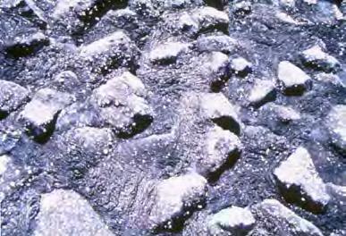
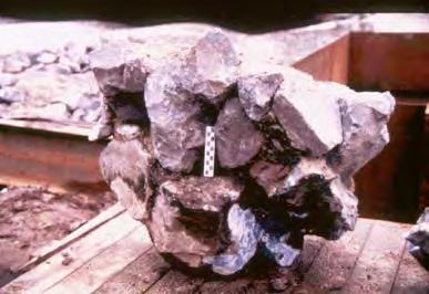
21 BRIDGE SCOUR EVALUATION PROCEDURES: Rock ROCK AT OR NEAR THE SURFACE Material Susceptibility to Scour Material Subtype Texas Cone Penetrometer Rock Clays Hard (Granite, Limestone, Shale) Susceptibility < 4 /100 blows Not susceptible Soft (Shale) < 12 /100 blows Mildly susceptible, but not considered over time span of one flood event Hard (Redbed, Shaley Clays, Very Stiff Clays) < 12 / 100 blows Mildly susceptible, but not considered over time span of one flood event Soft to Medium > 12 / 100 blows Susceptible to scour at a moderate rate Sands All All Very susceptible 21
22 BRIDGE SCOUR EVALUATION PROCEDURES: Rock ROCK PROFILE YEAR WSEL 51.5' NORMAL POOL 39.8' 50(1 )502(2 ) Elevation (ft) HEC-18 Sand Scour Calculations For the Channel Ystotal = Ysc + Ysp = ft LIMESTONE LEGEND DATE LINE Station (1 )50(1 ) Other Methods For the Channel Rock Eq.: TxDOT : Ystotal = 0.55 ft Ystotal = 0.00 ft non-scourable rock Rock at the Surface use Ystotal = 1 to 2 diam. example DS diam = 3 ft : Ystotal = 3-6 ft


23 BRIDGE SCOUR EVALUATION PROCEDURES: Rock Wetting and drying cycles make Clay and Shale susceptible to scour Highly weathered and fractured rock can be susceptible to scour 23
24 BRIDGE SCOUR EVALUATION PROCEDURES: Programs PROGRAMS AVAILABLE TO EVALUATE SCOUR: Cohesionless Soil: - HEC-RAS contains the HEC-18 sand contraction and pier scour equations, as well as Froehlich s equation - Florida DOT has a spreadsheet available to calculate pier scour ( - FHWA Hydraulic Toolbox ( Cohesive Soil: - HEC-RAS contains the HEC-18 sand contraction and pier scour equations. Reduce pier scour by multiplier. - FHWA Hydraulic Toolbox contains the SRICOS pier scour equation - SRICOS-EFA Program can be downloaded from Texas A&M ( 24
 Coarse Bed (i.e. large gravel) - Also contains contraction scour and abutment scour equations, as well as stone protection calculations for D50 and a channel analysis calculations.")
25 BRIDGE SCOUR EVALUATION PROCEDURES: Programs FHWA HYDRAULIC TOOLBOX FHWA HYDRAULIC TOOLBOX - Contains HEC-18 Sand Equations and various pier scour equations, such as: a) Florida DOT; b)sricos; c) Complex pier scour; d) Coarse Bed (i.e. large gravel) - Also contains contraction scour and abutment scour equations, as well as stone protection calculations for D50 and a channel analysis calculations. 25


26 BRIDGE SCOUR EVALUATION PROCEDURES: Programs FHWA HYDRAULIC TOOLBOX Stone Protection Bridge Scour Analysis Channel Analysis For scour type selected this allows one to select the equation that you want to use Scour Type: Abutment Scour Contraction Scour Long term-term Degradation Pier Scour Special Condition contains SRICOS Pier Scour 26
27 Bridge Scour: Procedures, Coding, and Documentation IF THE SCOUR PREDICTIONS ARE EXCESSIVE Verify Hydrology/Hydraulics (see TxDOT Research Project Empirical Flow Parameters A Tool for Hydraulic Model Validity Assessment) Check the HEC-RAS model Some Items to Check: Make sure the geometry is correct. Make sure that you have checked the expansion and contraction coefficients for the sections around the bridge. The default values are too low to capture the energy loss. Make sure that you have used the ineffective flow conditions for the sections adjacent to the bridge and have used them appropriately. You may have to adjust the Manning s n values for the internal bridge cross sections. Compare historic data of cross section changes at the bridge with the scour predictions 27
28 BRIDGE SCOUR EVALUATION PROCEDURES: Existing Bridges BRIDGE SCOUR BRIDGE TYPE NEW BRIDGES EXISTING BRIDGES KNOWN FOUNDATION KNOWN FOUNDATION UNKNOWN FOUNDATION SCOUR EVALUATION PROCEDURES FOR EXISTING BRIDGES 28
29 BRIDGE SCOUR EVALUATION PROCEDURES: Existing Bridges BRIDGE SCOUR BRIDGE TYPE EXISTING BRIDGES KNOWN FOUNDATION FOLLOW TxDOT GEOTECHNICAL MANUAL USE THE TSEAS MANUAL 29
30 BRIDGE SCOUR EVALUATION PROCEDURES: Existing Bridges Texas Department of Transportation Texas Secondary Evaluation And Analysis For Scour (TSEAS) for Texas Bridge Scour Program The TSEAS Manual is used as a screening process to evaluate existing bridges and to determine the maximum allowable scour depth. Prepared By The Division of Bridges and Structures Hydraulics Section September 1993 TSEAS Manual includes both an observational scour analysis and an engineering scour analysis. 30
31 BRIDGE SCOUR EVALUATION PROCEDURES: Existing Bridges CRITICAL ROUTES = Evacuation Roadways; Emergency System Roadways; High AADT Roadways; School Routes with no Alternative Paths TSEAS Manual KNOWN FOUNDATION Existing Structures Concise Analysis Not to be used on bridges: - On Interstates - On Critical Routes This is a simplified scour analysis that estimates allowable scour and pier scour, but only determines if contraction scour is a problem. Secondary Screening ONLY USED on Low Volume Off-System Bridges This observation method includes a qualitative evaluation of the stability of the scour at the bridge. 31
32 BRIDGE SCOUR EVALUATION PROCEDURES: Single Span Bridges BRIDGE SCOUR BRIDGE TYPE SINGLE SPAN BRIDGES KNOWN FOUNDATION - THESE NEED TO BE EVALUATED FOR SCOUR - FOLLOW THE TxDOT GEOTECHNICAL MANUAL - CALCULATE CONTRACTION SCOUR 32


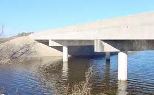
33 BRIDGE SCOUR EVALUATION PROCEDURES: Single Span Bridges SINGLE SPAN BRIDGE January 2013 Bridge was opened to traffic in 2007 View looking downstream north/northwest View looking upstream - south Undermining of the riprap southwest corner View looking west - southwest 33


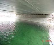
34 BRIDGE SCOUR EVALUATION PROCEDURES: Single Span Bridges SINGLE SPAN BRIDGE October 2013 View looking upstream - south View looking west - northwest View looking east View looking north under the west abutment 34
35 BRIDGE SCOUR EVALUATION PROCEDURES: Bridge Class Culverts WHAT ABOUT BRIDGE CLASS CULVERTS? BRIDGE CLASS CULVERTS WITH BOTTOMS WITHOUT BOTTOMS 35

36 BRIDGE SCOUR EVALUATION PROCEDURES: Bridge Class Culverts with Bottoms BRIDGE CLASS CULVERTS WITH BOTTOMS March, 2008 Guidelines were sent to each District on how to evaluate bridge class culverts for scour Districts can perform the evaluations 36


37 BRIDGE SCOUR EVALUATION PROCEDURES: Bridge Class Culverts without Bottoms BRIDGE CLASS CULVERTS WITHOUT BOTTOMS Need to be analyzed for scour using on of the methods outlined in the TxDOT Geotechnical Manual Chapter 5 Section 5 Scour or using the FHWA Manual - Bottomless Culvert Scour Study: Phase II Laboratory Report. If these are used the spread footing foundations should be supported on drilled shafts. 37
38 BRIDGE SCOUR EVALUATION PROCEDURES: Bridges with Unknown Foundations BRIDGE SCOUR BRIDGE TYPE NEW BRIDGES EXISTING BRIDGES KNOWN FOUNDATION KNOWN FOUNDATION UNKNOWN FOUNDATION GEOTECHNICAL BRANCH WILL ANALYZE BRIDGES WITH UNKNOWN FOUNDATIONS 38
39 BRIDGE SCOUR DOCUMENTATION SCOUR DOCUMENTATION 39

40 BRIDGE SCOUR DOCUMENTATION SCOUR SUMMARY SHEETS Scour Summary Sheets were developed for bridges with known foundations and bridge class culverts Guidelines for completing them and examples were sent out to the Districts in March 2008 These are to be used to document the initial coding of bridges for scour and any changes in the coding of existing structures. To be placed in the Bridge Inspection Folder and in InspectTech. 40

41 BRIDGE SCOUR DOCUMENTATION Recommended coding Signed/Sealed document to be placed in the Bridge Inspection Folder/InspectTech Basis of Coding describes the: 1) Current coding; 2) Updated coding; 3) The reason for updating the coding Current Conditions describes the most recent channel conditions Future Action describes a change in channel profile that would be considered significant enough to warrant an additional evaluation 41
42 BRIDGE SCOUR DOCUMENTATION Signed/Sealed document to be placed in the Bridge Inspection Folder/InspectTech Indicate the appropriate Item 113 code for the bridge based on the evaluation. Describe/document the method(s) used to evaluate the bridge for scour. Describe/document the current conditions of the scour at the bridge. Describe/document the elevation that the scour depth can reach prior to the bridge having to be re-evaluated. 42
43 BRIDGE SCOUR DOCUMENTATION GUIDANCE FOR FUTURE ACTION USE OF MAXIMUM ALLOWABLE SCOUR DEPTH AND GUIDELINE LIMITS ON WHEN TO CODE A BRIDGE A 3, 2, OR 1 IN ITEM

44 BRIDGE SCOUR DOCUMENTATION WORKSHEET # 1 ALLOWABLE SCOUR DEPTH BENT NUMBER: #3 LOCATION: 1 Elevation of natural ground at base of pier 459 ft 2 Elevation of bottom pier/drill shaft 423 ft 3 Depth of Embedment 36 ft 4 Top of Column Elevation 466 ft 5 Total length of column 7 ft Enter ds - drilled shaft, pt - trestle pile, phs - h/square pile ds 6 7 or ptb - timber pile Diameter of column/drill shaft or pile (inches) Maximum Allowable scour depth based on Bearing 30 in 0.5*36 = 18 ft Use the guidelines for - Max. Allow. Scour Depth/3 = 18/3 = 6 ft - Max. Allow. Scour Depth*(2/3) = 18*(2/3) = 12 ft Bridge should be coded a 3 when the scour level is: 6 ft < Scour Depth < 12 ft Bridge should be coded a 2 when the scour level is: 12 ft < Scour Depth < 18 ft 9 Allowable unsupported factor - ft/in of dia. 1.5 Unsupported Column Length = Maximum Allowable scour depth: Lateral Stability = 30*1.5 = 45 ft 45 7 = 38 ft 10 Max. Allow. Scour Depth= 18 ft Maximum Scour Depth is controlled by Bearing, not Lateral Stability 44
45 BRIDGE SCOUR DOCUMENTATION DOCUMENTATION ALL SCOUR CODINGS NEED TO BE WELL DOCUMENTED, WITH THE DOCUMENTATION PLACED IN THE BRIDGE INSPECTION FOLDER AND IN InspectTech 45
46 SCOUR COUNTERMEASURES SCOUR COUNTERMEASURES 46
47 SCOUR COUNTERMEASURES SCOUR COUNTERMEASURES RIGID FLEXIBLE Impermeable Does NOT conform to changes in the supporting surface Permeable Conforms to changes in the supporting surface 47
48 SCOUR COUNTERMEASURES SCOUR COUNTERMEASURES CONCRETE RIPRAP RIGID GROUTED STONE PROTECTION 48


49 SCOUR COUNTERMEASURES: Rigid Rigid Protection Visible Problems Undermined Voided Settled Cracked 49


50 SCOUR COUNTERMEASURES STONE PROTECTION SCOUR COUNTERMEASURES FLEXIBLE INTERLOCKING ARTICULATED CONCRETE BLOCKS GABIONS GABION MATTRESS CONCRETE ARMOR UNITS 50

51 SCOUR COUNTERMEASURES Gabion mattresses Stone protection Concrete Armor Unit 51

52 SCOUR COUNTERMEASURES: Flexible The Geotechnical Branch recommends the use of flexible countermeasures, when applicable ADVANTAGES Design is adaptable Construction is not complicated and does not require specialty equipment Has a natural appearance Failures are easily identified and can be fixed DISADVANTAGES No standard must be designed May be hard to obtain in some parts of Texas Near vertical gabions can be difficult to repair Easily inspected and repaired Rough surface Adjusts to distortions and local displacement of the foundation soil Movements can occur without complete failure and protection is still functional 52

53 SCOUR COUNTERMEASURES: Flexible - STONE PROTECTION In the 2014 Specification for Item 432 Riprap, is the size equal to the thickness? No. Why? In the 2004 Specification the size was equal to the thickness, but some installations have had problems. In the 2014 Specification the size is not equal to the thickness. Nearly all design methods for stone protection state that the thickness should be the larger of: 1) the largest size particle allowed (Dmax); or 2) twice the D50 size. Typically, the thickness is governed by 2 x D50, so a simple estimate of the thickness is 1.5 x size. Example, assume an 18 inch size, then from Table 2 the largest size is Dmax = and D50 = Now Dmax = < 2 x D50 = 2 x x = The 2 x D50 is the larger of the two values, so it would control the thickness. In the 2014 Specification Book the size is listed and the thickness must be determined. This allows the engineer to select whatever thickness meets the need of the job. Stone Protection (Size) Thickness = XX 53
54 Scour: Evaluation and Countermeasures SUMMARY Scour at bridges is complex, but an evaluation of it is required to ensure the bridge is stable and the traveling public is safe Documenting the scour conditions indicates the current status of the bridge regarding its vulnerability to scour and what to do during flooding events Scour countermeasures are often required to prevent future scour and having the bridge become scour critical Flexible countermeasures are recommended and often required to stabilize conditions at the bridge 54
55 Scour: Evaluation and Countermeasures QUESTIONS? 55
56 Copyright 2017 Texas Department of Transportation All Rights Reserved Entities or individuals that copy and present state agency information must identify the source of the content, including the date the content was copied. Entities or individuals that copy and present state agency information on their websites must accompany that information with a statement that neither the entity or individual nor the information, as it is presented on its website, is endorsed by the State of Texas or any state agency. To protect the intellectual property of state agencies, copied information must reflect the copyright, trademark, service mark, or other intellectual property rights of the state agency whose protected information is being used by the entity or individual. Entities or individuals may not copy, reproduce, distribute, publish, or transmit, in any way this content for commercial purposes. This presentation is distributed without profit and is being made available solely for educational purposes. The use of any copyrighted material included in this presentation is intended to be a fair use of such material as provided for in Title 17 U.S.C. Section 107 of the US Copyright Law. 56
B422 - PRECAST REINFORCED CONCRETE BOX CULVERTS AND BOX SEWERS - OPSS 422
 B422 - PRECAST REINFORCED CONCRETE BOX CULVERTS AND BOX SEWERS - OPSS 422 422.1 GENERAL The work under these tender items consists of the fabrication and installation in open cut of precast reinforced
New Directions in Scour Monitoring
 New Directions in Scour Monitoring Beatrice E. Hunt, P.E., AECOM Gerarda M. Shields, Ph.D., P.E., New York City College of Technology Gerald Price, ETI Instrument Systems, Inc. New Directions in Scour
50.24 Type, Size and Location Plans for Culverts, Bridges and Culvert Bridges
 50.24 Culverts, Bridges and Culvert Bridges Type, Size and Location (T, S & L) Plans shall be required for all Bridges, Culvert Bridges and Culverts of eight-foot (8') clear span or greater as follows:
CE 365K Exercise 2: HEC-RAS Modeling Spring 2014 Hydraulic Engineering Design
 CE 365K Exercise 2: HEC-RAS Modeling Spring 2014 Hydraulic Engineering Design This exercise was prepared by Fernando R. Salas and David R. Maidment Introduction In this exercise, we will learn how to setup
Field Observations and One-Dimensional Flow Modeling of Summit Creek in Mack Park, Smithfield, Utah
 Sediment Transport Workshop, Utah State University, 1 August 2017 Field Observations and One-Dimensional Flow Modeling of Summit Creek in Mack Park, Smithfield, Utah I. Goals for learning and discussion:
Helical Pier Frequently Asked Questions
 Helical Pier Basics Q: What is a Helical Pier? A: A helical pier or pile is an extendable deep foundation system with helical bearing plates welded to a central steel shaft. Load is transferred from the
HEXAGONAL DOUBBLE TWISTED GABION & ROCK FALL MATRESSES
 Menufatchurar of HEXAGONAL DOUBBLE TWISTED GABION & ROCK FALL MATRESSES As per IS 16014 (2012): Mechanically woven, double -twisted, hexagonal Wire Mesh Gabions, Revet Mattresses and Rock fallnetting(
CVE 372 HYDROMECHANICS OPEN CHANNEL FLOW II
 CVE 372 HYDROMECHANICS OPEN CHANNEL FLOW II Dr. Bertuğ Akıntuğ Department of Civil Engineering Middle East Technical University Northern Cyprus Campus CVE 372 Hydromechanics 1/68 Overview 3.4 Rapidly Varied
STABILITY. SECURITY. INTEGRITY.
 MODEL 150 HELICAL ANCHOR SYSTEM PN #MBHAT STABILITY. SECURITY. INTEGRITY. 150 Helical Anchor System About Foundation Supportworks is a network of the most experienced and knowledgeable foundation repair
The Basics. HECRAS Basis Input. Geometry Data - the basics. Geometry Data. Flow Data. Perform Hydraulic Computations. Viewing the Output
 The Basics HECRAS Basis Input Geometry Data. Flow Data. Perform Hydraulic Computations by G. Parodi WRS ITC The Netherlands Viewing the Output ITC Faculty of Geo-Information Science and Earth Observation
With time, the evolution of anchors have led to different designs More than one anchor type may be suitable for a particular purpose Thus there are
 Supreme range of Soil & rock anchors Introduction Used to anchor into concrete, masonry, stone With time, the evolution of anchors have led to different designs More than one anchor type may be suitable
DEEP FOUNDATION TYPES DESIGN AND CONSTRUCTION ISSUES
 DEEP FOUNDATION TYPES DESIGN AND CONSTRUCTION ISSUES OFFICE OF STRUCTURAL ENGINEERING OHIO DEPARTMENT OF TRANSPORTATION JAWDAT SIDDIQI P.E. ASSISTANT ADMINISTRATOR Reliability Index #&! #&!!" # $%!" #
Module 5 : Design of Deep Foundations. Lecture 20 : Introduction [ Section 20.1 : Introduction ]
![Module 5 : Design of Deep Foundations. Lecture 20 : Introduction [ Section 20.1 : Introduction ]](/thumbs/82/86090197.jpg "Module 5 : Design of Deep Foundations. Lecture 20 : Introduction [ Section 20.1 : Introduction ]") Lecture 20 : Introduction [ Section 20.1 : Introduction ] Objectives In this section you will learn the following Introduction Lecture 20 : Introduction [ Section 20.1 : Introduction ] INTRODUCTION The
Lecture 20 : Introduction [ Section 20.1 : Introduction ] Objectives In this section you will learn the following Introduction Lecture 20 : Introduction [ Section 20.1 : Introduction ] INTRODUCTION The
6. Performing Organization Code
 Technical Report Documentation Page 1. Report No. TX-00/0-3970-1 2. Government Accession No. 3. Recipient s Catalog No. 4. Title and Subtitle REMOTE BRIDGE SCOUR MONITORING: A PRIORITIZATION AND IMPLEMENTATION
ABC and Innovative Bridge Construction for Minnesota Local Roads
 ABC and Innovative Bridge Construction for Minnesota Local Roads May 23, 2013 To box the cha of t unl qua gra ma all g You ma add Tex Chris Werner, PE Senior Bridge Engineer HDR Engineering, Inc. 763-278-5918
Comparing Guided Auger Boring Techniques under Challenging Conditions
 North American Society for Trenchless Technology (NASTT) NASTT s 2014 No-Dig Show Orlando, Florida April 13-17, 2014 TM1-T4-02 Comparing Guided Auger Boring Techniques under Challenging Conditions Matthew
PART XIII: HYDRAULIC/ HYDROLOGY SURVEYS
 PART XIII: HYDRAULIC/ HYDROLOGY SURVEYS 13.1 Purpose and Scope Hydraulic surveys are required for flow analysis to determine bridge and culvert design characteristics. A hydraulic survey is usually but
2.5 Design of Channels
 2.6 Design of Open Channels Open channels have uses in urban stormwater drainage urban sanitary-sewer systems irrigation delivery systems In the next few lectures, we'll discuss the design procedure for
transmit foundation loads
 PILES Long, slender members that transmit foundation loads through soil strata of low bearing capacity or through water to deeper soil or rock strata having a high bearing capacity. End bearing piles End
NALYSIS OF STABILIZING SLOPES USING VERTICAL PILES
 NALYSIS OF STABILIZING SLOPES USING VERTICAL PILES Mahmoud S. Abdelbaki: Lecturer, Gehan E. Abdelrahman: Lecturer, Youssef G. Youssef :Assis.Lecturer, Civil Eng. Dep., Faculty of Eng., Cairo University,
Piles Capacity Reference Manual
 Piles Capacity Reference Manual hetge hetge geotechnics on the go Piles Capacity Reference Manual May 22, 2012 Version: PC-1.2.120728b hetge LLC Moscow Virginia Istanbul E info@hetge.com W www.hetge.com
SUMMARY SHEETS OF BAR COUPLER CONNECTIONS
 APPENDIX A SUMMARY SHEETS OF BAR COUPLER CONNECTIONS NCHRP 12 88 Connection Evaluations Appendix A A 1 APPENDIX A SUMMARY SHEETS OF BAR COUPLER CONNECTIONS NCHRP 12 88 Connection Evaluations Appendix
PCCP Preservation Steps to Take to Extend Pavement Life and Performance of Your Concrete Pavements
 PCCP Preservation Steps to Take to Extend Pavement Life and Performance of Your Concrete Pavements Larry Scofield, P.E. International Grooving and Grinding Association 1 Big Preservation Everybody Wins
RE: Engineered Riffle Concepts for Sodom Dam Removal Grade Control Elements
 November 19, 2009 Ms. Melissa Jundt NOAA Fisheries Hydropower Division 1201 NE Lloyd Boulevard, Suite 1100 Portland, Oregon 97232 RE: Engineered Riffle Concepts for Sodom Dam Removal Grade Control Elements
Boardwalk Construction Guidelines
 Boardwalk Construction Guidelines Acton Land Stewardship Committee Acton, Massachusetts 1 Rev. 2-2/9/2018 NOTICE TO AGENCIES OUTSIDE THE ACTON LAND STEWARDSHIP COMMITTEE THE BOARDWALK CONSTRUCTION GUIDELINES
Re: Survey of constructed cross section per Restoration Framework on Wind River, Fremont County, WY
 1-11-17 LeClair Irrigation District 1418 Cowboy Lane Riverton, WY 82501 (307) 856-4018 Re: Survey of constructed cross section per Restoration Framework on Wind River, Fremont County, WY Dear Mr. Hoelzen,
Limit Equilibrium including Shear Capacity for Launched Soil Nails. Matthew Birchmier, P.E.
 Limit Equilibrium including Shear Capacity for Launched Soil Nails Matthew Birchmier, P.E. The Soil Nail Launcher Declassified British Military Cannon modified to Launch Soil Nails War on shallow landslides
SKIN FRICTION OF PILES COATED WITH BITUMINOUS COATS Makarand G. Khare 1 and Shailesh R. Gandhi 2
 SKIN FRICTION OF PILES COATED WITH BITUMINOUS COATS Makarand G. Khare 1 and Shailesh R. Gandhi 2 1 Ph.D Student, Dept. of Civil Engineering, Indian Institute of Tech. Madras, Chennai, India-600036 Email:
Floodplain Modeling 101. Presentation Goals
 Floodplain Modeling 101 Presenter: Joseph L. Miller, P.E., CFM 2016 INAFSM Conference Presentation Goals Introduction to Indiana s and FEMA s floodplain modeling technical requirements for riverine modeling
Compensatory Mitigation Monitoring Report Aquatic Habitat Improvement City of Montrose Whitewater Park, Montrose County, Colorado March 6, 2014
 Compensatory Mitigation Monitoring Report Aquatic Habitat Improvement City of Montrose Whitewater Park, Montrose County, Colorado March 6, 2014 i. Project Overview 1. USACE # # SPK 2013 00851 2. Permittee:
Precast Concrete Pavement Background Concepts. Project 1517 FHWA, CTR & TxDOT Gary Graham November 15, 2001
 Precast Concrete Pavement Background Concepts Project 1517 FHWA, CTR & TxDOT Gary Graham November 15, 2001 Project Background CTR contracted by FHWA/TxDOT to investigate the feasibility of using precast
Authorized Agent: City of Manassas Check List Attached: Contact: Address: Phone Number: Fax Number: Developer s Name: Phone Number:
 CITY OF MANASSAS DEPARTMENT OF COMMUNITY DEVELOPMENT DEVELOPMENT SERVICES DIVISION 9027 Center Street Room 201 Manassas, Virginia, 20110 Phone: 703-257-8278 Fax: 703-257-5831 Application Date: APPLICANT
North Carolina No-Rise Guidance Document
 North Carolina No-Rise Guidance Document June 4, 2015 Atlanta, GA Dan Brubaker, PE, CFM NFIP Engineer (919) 825-2300 Dan.Brubaker@ncdps.gov Purpose Provide guidance for No-Rise preparation Engineers Provide
SECTION 100 PRELIMINARY CONSIDERATIONS & INSTRUCTIONS
 SECTION 100 PRELIMINARY CONSIDERATIONS & INSTRUCTIONS 101 General 102 Submittal Requirements A. Initial Submittal B. Second Submittal 103 Plan Requirements A. Subdivisions B. Site Plans 104 Approval of
SPECIFICATIONS FOR THE MANUFACTURE AND DESIGN OF PRECAST THREE SIDED ARCH STRUCTURES, WINGWALLS AND HEADWALLS
 SPECIFICATIONS FOR THE MANUFACTURE AND DESIGN OF PRECAST THREE SIDED ARCH STRUCTURES, WINGWALLS AND HEADWALLS 1. DESCRIPTION THESE SPECIFICATIONS ARE FOR A PRECAST THREE SIDED ARCH STRUCTURE, HEADWALLS
INFLUENCE OF PILES ON LOAD- SETTLEMENT BEHAVIOUR OF RAFT FOUNDATION
 INFLUENCE OF PILES ON LOAD- SETTLEMENT BEHAVIOUR OF RAFT FOUNDATION BALESHWAR SINGH Department of Civil Engineering Indian Institute of Technology Guwahati Guwahati 78139, India NINGOMBAM THOIBA SINGH
PCI Update on Transportation Activities and elearning Modules for AASHTO Technical Committee T-4 AASHTO SCOBS --- Spokane Washington
 PCI Update on Transportation Activities and elearning Modules for AASHTO Technical Committee T-4 AASHTO SCOBS --- Spokane Washington June 2017 William N. Nickas, P.E. Managing Director, Transportation
Quality Control and Quality Assurance Guide
 Quality Control and Quality Assurance Guide Bridge Division, Design Section April 2017 Table of Contents Chapter 1 About this Guide... 3 Chapter 2 Goals and Objectives... 5 Chapter 3 Participants... 6
Finite Element Study of Using Concrete Tie Beams to Reduce Differential Settlement Between Footings
 Finite Element Study of Using Concrete Tie Beams to Reduce Differential Settlement Between Footings AMIN H. ALMASRI* AND ZIAD N. TAQIEDDIN** *Assistant Professor, Department of Civil Engineering, Jordan
This document is a preview generated by EVS
 INTERNATIONAL STANDARD ISO 19901-4 Second edition 2016-07-15 Petroleum and natural gas industries Specific requirements for offshore structures Part 4: Geotechnical and foundation design considerations
Assembly Instructions for. for 31" MGS (Midwest Guardrail System) ROAD SYSTEMS, INC.
 ROAD SYSTEMS, INC.") MSKT Assembly Instructions for MASH Tangent Terminal for 31" MGS (Midwest Guardrail System) ROAD SYSTEMS, INC. P. O. Box 2163 Big Spring, Texas 79721 Phone: (432) 263-2435 FAX: (432) 267-4039 Technical
MSKT Assembly Instructions for MASH Tangent Terminal for 31" MGS (Midwest Guardrail System) ROAD SYSTEMS, INC. P. O. Box 2163 Big Spring, Texas 79721 Phone: (432) 263-2435 FAX: (432) 267-4039 Technical
SECTION DEWATERING TANKAGE PART 1 - GENERAL 1.1 RELATED DOCUMENTS
 SECTION 31 23 19 - DEWATERING TANKAGE PART 1 - GENERAL 1.1 RELATED DOCUMENTS A. Drawings and general provisions of the Contract, including General and Supplementary Conditions and Division 1 Specification
Application of Advanced Materials and New Detailing for ABC Column Connections
 Application of Advanced Materials and New Detailing for ABC Column Connections Mostafa Tazarv, PhD Assistant Professor Department of Civil and Environmental Engineering South Dakota State University (SDSU)
Dewatering. Deep Wells Vacuum Wellpoints Eductor Wells Artesian Conditions System Design Water Treatment.
 Dewatering Deep Wells Vacuum Wellpoints Eductor Wells Artesian Conditions System Design Water Treatment www.malcolmdrilling.com Deep Wells Vacuum Wellpoints Eductor Wells Artesian Conditions System Design
BRACE ASSEMBLIES FOR WIRE FENCES. What They Are - How They Work - How To Construct Them
 Fencing Order No. 307.220-1 Agdex: 724 March 1996 BRACE ASSEMBLIES FOR WIRE FENCES What They Are - How They Work - How To Construct Them When constructing wire fences, brace assemblies are required to
SImulation of MONopile installation - JIP SIMON
 SImulation of MONopile installation - JIP SIMON Ahmed Elkadi Deltares 14 February 2019 MOTIVATION Vanbeekimages.com 14 februari 2019 Matchmaking Day 2019 2 Global substructure statistics/trends 2016 Offshore
Manual. Pile Design [NEN method]
![Manual. Pile Design [NEN method]](/thumbs/75/72745348.jpg "Manual. Pile Design [NEN method]") Manual Pile Design [NEN method] The information contained in this document is subject to modification without prior notice. No part of this document may be reproduced, transmitted or stored in a data retrieval
Manual Pile Design [NEN method] The information contained in this document is subject to modification without prior notice. No part of this document may be reproduced, transmitted or stored in a data retrieval
Levee Risk Assessments
 Levee Risk Assessments Overview of the USACE Semi-Qualitative Risk Assessment Process for Levees Michael Kynett, PE Levee Safety Program Manager Sacramento District, USACE Levee State-of-the-Practice Symposium
ANALYSIS OF PILE-RAFT FOUNDATIONS NON- RESTED AND DIRECTLY RESTED ON SOIL
 ANALYSIS OF PILE-RAFT FOUNDATIONS NON- RESTED AND DIRECTLY RESTED ON SOIL Elsamny M. Kassem1, Abd EL Samee W. Nashaat2 and Essa. Tasneem.A1 1 Civil Engineering Department, Al-Azhar University, Cairo, Egypt
SKT-SP Tangent Terminal
 Assembly Instructions for metric SKT-SP Tangent Terminal & FLEAT-SP Flared Terminal SP Standard Post System Guardrail Terminals ROAD SYSTEMS, INC. P. O. Box 2163 Big Spring, Texas 79721 Phone: (432) 263-2435
CHAPTER 1: TITLE SHEET and GENERAL LAYOUT
 CHAPTER 1: TITLE SHEET and GENERAL LAYOUT AREA OF ENVIRONMENTAL SENSITIVITY It is important to show the areas of environmental sensitivity in the plan to make sure these areas are not impacted. These locations
Experimental Study on Pile Groups Settlement and Efficiency in Cohesionless Soil
 Experimental Study on Pile Groups Settlement and Efficiency in Cohesionless Soil Elsamny, M.K. 1, Ibrahim, M.A. 2, Gad S.A. 3 and Abd-Mageed, M.F. 4 1, 2, 3 & 4- Civil Engineering Department Faculty of
Example Application C H A P T E R 4. Contents
 C H A P T E R 4 Example Application This chapter provides an example application of how to perform steady flow water surface profile calculations with HEC-RAS. The user is taken through a step-by-step
Deep Creek Canyon US Highway 12
 Deep Creek Canyon US Highway 12 ABC Techniques in Rural Montana Jim Scoles Morrison-Maierle 1 Location Deep Creek Canyon US Highway 12 Helena National Forest Great Falls Map of mid MT showing Location
Forming and Shoring Product Selector
 Forming and Shoring Product Selector Including RedForm LVL and RedForm-I65, I90, and I90H s Lightweight for Fast Installation Resists Bowing, Twisting, and Shrinking Available in Long Lengths Uniform and
State College Area School District
 State College Area School District The following is a guideline for project design submittals to the Facility Committee of the State College Area School District. During the design process the committee
URBAN DRAINAGE AND FLOOD CONTROL DISTRICT
 URBAN DRAINAGE AND FLOOD CONTROL DISTRICT Digital Flood Hazard Area Delineation (DFHAD) Guidelines July 2009 Prepared by 720 South Colorado Boulevard Suite 410 S Denver, Colorado 80246 phone (303) 757-3655
SPECIFICATIONS FOR THE INSTALLATION OF CONDUIT SYSTEMS IN RESIDENTIAL SUBDIVISIONS. Notification of Completed Conduit Sections
 SPECIFICATIONS FOR THE INSTALLATION OF CONDUIT SYSTEMS IN RESIDENTIAL SUBDIVISIONS Section 1 Definitions 2 Scope of Work 3 Extent of Work 4 Inspection and Performance of Work 5 Trenching 6 Duct Installation
Presented By: Todd Ward Project Manager
 Presented By: Todd Ward Project Manager Mailing Address All submittals for LOMRs and CLOMRs Harris County should be directed to Harris County Flood Control District. Submittals can be mailed or hand-delivered
METHODOLOGY TO DEMONSTRATE PILE CAPACITY IN RELAXING GROUND
 286 METHODOLOGY TO DEMONSTRATE PILE CAPACITY IN RELAXING GROUND T. A. Peiris 1, B. Morris 2, R. Kelly 1, K. Chan 3 1 Coffey Geotechnics, Sydney, Australia 1 E-mail: Ashok.Peiris@leicon.com.au, Ashok_Peiris@coffey.com
PREDICTING COMPACTION GROUT QUANTITIES IN SINKHOLE REMEDIATION
 PREDICTING COMPACTION GROUT QUANTITIES IN SINKHOLE REMEDIATION Edward D. Zisman Cardno ATC, 5602 Thompson Center Court, Suite 405, Tampa, Florida 34689 Abstract Predicting the required quantity of grout
APPLICATION FOR SITE PREPARATION PERMIT
 Engineering Division 550 Landa Street New Braunfels, Texas 78130 (830) 221-4020 1. Subdivision/Plat Name: Location Description/ Nearest Intersection: Acreage: APPLICATION FOR SITE PREPARATION PERMIT No.
Webinar Questions & Answers: Investigating Wind & Hail Damage
 Webinar Questions & Answers: Investigating Wind & Hail Damage Section A: Hail 1. Can hail direction change in a single storm, damaging all slopes of a structure? Hail can fall straight down or at an angle,
Washington County Road Engineering Plan Submittal/Review Checklist
 Washington County Road Engineering Plan Submittal/Review Checklist Washington County Land Use Case File Number: Parcel(s): Developer/Owner Name(s): Developer/Owner E-mail(s): The following elements should
Comparison of the Behavior for Free Standing Pile Group and Piles of Piled Raft
 Engineering and Technology Journal Vol. 36, Part A, No.4, 218 DOI: http://dx.doi.org/1.3684/etj.36.4a.3 Awf A. Al-Kaisi Building & Const. Eng. Dept. University of Technology, Baghdad, Iraq Comparison of
FOUNDATION AUGERS. FOR USE ON THE FOLLOWING CARRIES Foundation Drill Rigs
 FOR USE ON THE FOLLOWING CARRIES Foundation Drill Rigs PENGO AUGER SOIL CHART Pengo has developed the chart below to help you decide which auger will be best suited for your project. The above triangles
State of the Art Precast, Prestressed Concrete Bridges and Industry Innovations
 State of the Art Precast, Prestressed Concrete Bridges and Industry Innovations William N. Nickas, P.E. Managing Director, Transportation Services Precast/Prestressed Concrete Institute Chicago, IL. LEARNING
CITY OF LA MARQUE CHAPTER GRAPHIC REQUIREMENTS CONSTRUCTION PLAN AND MISCELLANEOUS REQUIREMENTS
 CITY OF LA MARQUE CHAPTER 2 -------------------------------------------- GRAPHIC REQUIREMENTS CONSTRUCTION PLAN AND MISCELLANEOUS REQUIREMENTS CHAPTER 2 ------------------------------------------------
A WORD ABOUT BRACING PART A - BUILDING A STRAIGHT, PILE BENT, OPEN DECK TRESTLE. Built in Place, Straight
 BUILDING LARGE SCALE TRESTLES You have many options when building a large scale trestle. The choices you make may be based on the prototype you are modeling; the era or industry you are modeling; or, simply
CONSTRUCTION SPECIFICATION FOR PRECAST REINFORCED CONCRETE BOX CULVERTS AND BOX SEWERS
 ONTARIO PROVINCIAL STANDARD SPECIFICATION METRIC OPSS 422 MAY 1993 CONSTRUCTION SPECIFICATION FOR PRECAST REINFORCED CONCRETE BOX CULVERTS AND BOX SEWERS 422.01 SCOPE 422.02 REFERENCES 422.03 DEFINITIONS
Module 9 Lecture 35 to 40 DRILLED-SHAFT AND CAISSON FOUNDATIONS
 Topics Module 9 Lecture 35 to 40 DRILLED-SHAFT AND CAISSON FOUNDATIONS 35.1 INTRODUCTION 35.2 DRILLED SHAFTS 35.3 TYPES OF DRILLED SHAFTS 35.4 CONSTRUCTION PROCEDURES Use of Casings and Drilling Mud Inspection
Mounting of poles and foundations Rette produkt Til rette opgave
 Mounting of poles and foundations Rette produkt Til rette opgave 12/04/2018 Burying and mounting poles General When mounting poles, the door of the pole must always match the specific pole, with which
Description of exam material for Inland waterways and locks
 For reasons of simplicity, the description underneath is based on the printed course notes. Page numbers are indicated to facilitate the studying process. It is strongly recommended that the student is
Diamond Knowledge Base. Inductive Loop Guide. Introduction
 Diamond Knowledge Base Inductive Loop Guide Introduction An inductive loop is basically a metal detector installed in the surface of the roadway. It consists of electrical wire embedded in the roadway,
KKR S. 6 th St. to I-94 Bridge Project Location. Expanded Floodplains
 Kinnickinnic River Watercourse Rehabilitation Early Out Project Achieving Multiple Design Objectives Thomas R. Sear, PE, CFM Short Elliott Hendrickson Patrick C. Elliott, PE Milwaukee Metropolitan Sewerage
INDEX PAGE RELEASE SECTION NUMBER DATE
 INSTALLATION INSTRUCTIONS For Wind Zone 1 (other Wind Zones available on request) Version 11/20/2002 INDEX PAGE RELEASE SECTION NUMBER DATE Approval INTRODUCTION 2 2/26/2001 GENERAL INSTALLATION 3 2/26/2001
In response to a request from Water Rights Branch, a short. In general, the sequence of post glacial events in the immediate. D. M.
 . TO Dr. J. C. Foweraker......!...... C&* Groundwater Div i s ion... GOVERNMENT OF BRITISH COLUMBIA M EM0 RAN DU M D. M. Callan Groundwater Division... July 6th... 19... 71... SUBJECT GROUNDWATER INVESTIGATION
Ecological Restoration Drafting & Design Guidelines
 Ecological Restoration Drafting & Design Guidelines Version 2.0 July 2017 Philadelphia Water Ecological Restoration Drafting & Design Guidelines Table of Contents 1.0 INTRODUCTION...2 2.0 GENERAL PLAN
Study on embedded length of piles for slope reinforced with one row of piles
 Journal of Rock Mechanics and Geotechnical Engineering. 11, 3 (2): 7 17 Study on embedded length of piles for slope reinforced with one row of piles Shikou Yang, Xuhua Ren, Jixun Zhang College of Water
DEEP FOUNDATIONS PILES
 DEEP FOUNDATIONS PILES Pile foundation used to support structure when poor quality soil bearing capacity failure excessive settlement piles END BEARING PILES SKIN FRICTION PILES End bearing pile rests
A Full 3-D Finite Element Analysis of Group Interaction Effect on Laterally Loaded Piles
 Modern Applied Science; Vol. 12, No. 5; 2018 ISSN 1913-1844 E-ISSN 1913-1852 Published by Canadian Center of Science and Education A Full 3-D Finite Element Analysis of Group Interaction Effect on Laterally
Water Surface Profiles
 United States Department of Agriculture Natural Resources Conservation Service Hydrology Computer Program for Water Issued October 1993 Revision March 2005 The United States Department of Agriculture (USDA)
GENERAL GUIDELINES FOR APPLICATION OF THE EXTENDED SUBTRACTION METHOD IN SASSI SOIL-STRUCTURE INTERACTION ANALYSIS
 Transactions, SMiRT-22 GENERAL GUIDELINES FOR APPLICATION OF THE EXTENDED SUBTRACTION METHOD IN SASSI SOIL-STRUCTURE INTERACTION ANALYSIS C. C. Chin 1, Nan Deng 2, and Farhang Ostadan 3 1 Senior Engineer,
Digitally Signed 06/02/2015
 Digitally Signed 06/0/05 Digitally Signed 06/0/05 Digitally Signed 06/0/05 FED. ROAD DIST. NO. STATE FED. AID PROJ. NO. SHEET NO. TOTAL SHEETS 6--5 6 ARK. JOB NO. 08057 6 8 075 QUANTITIES 5706 SUMMARY
POSTPRINT UNITED STATES AIR FORCE RESEARCH ON AIRFIELD PAVEMENT REPAIRS USING PRECAST PORTLAND CEMENT CONCRETE (PCC) SLABS (BRIEFING SLIDES)
 SLABS (BRIEFING SLIDES)") POSTPRINT AFRL-RX-TY-TP-2008-4582 UNITED STATES AIR FORCE RESEARCH ON AIRFIELD PAVEMENT REPAIRS USING PRECAST PORTLAND CEMENT CONCRETE (PCC) SLABS (BRIEFING SLIDES) Athar Saeed, PhD, PE Applied Research
POSTPRINT AFRL-RX-TY-TP-2008-4582 UNITED STATES AIR FORCE RESEARCH ON AIRFIELD PAVEMENT REPAIRS USING PRECAST PORTLAND CEMENT CONCRETE (PCC) SLABS (BRIEFING SLIDES) Athar Saeed, PhD, PE Applied Research
Seal Coats and Surface Treatments Fred J. Benson, Dean of Engineering A. and M. College of Texas College Station, Texas The construction, as here
 Seal Coats and Surface Treatments Fred J. Benson, Dean of Engineering A. and M. College of Texas College Station, Texas The construction, as here discussed, consists of an application of bituminous material
Piled raft foundation for the W-TOWER Tel Aviv
 Piled raft foundation for the W-TOWER Tel Aviv Prepared by A. Lehrer, S. Bar. 1. Introduction. Development of the world's largest cities dictated the need for high building housing in different soil conditions,
TYPICAL SECTIONS TYPICAL NO. 1 (MAINLINE) STA TO STA STA TO STA ROUNDING DETAIL TYPICAL NO.
 STA TO STA STA TO STA ROUNDING DETAIL TYPICAL NO.") FILL SECTION TYPICAL NO. 1 (MAINLINE) STA. 2434. TO STA. 244035.16 STA. 244396.83 TO STA. 2449. CUT SECTION ROUNDING DETAIL FILL SECTION TYPICAL NO. 3 (DETOUR) CUT SECTION STA. 242849.86 TO STA. 2453.88
FILL SECTION TYPICAL NO. 1 (MAINLINE) STA. 2434. TO STA. 244035.16 STA. 244396.83 TO STA. 2449. CUT SECTION ROUNDING DETAIL FILL SECTION TYPICAL NO. 3 (DETOUR) CUT SECTION STA. 242849.86 TO STA. 2453.88
Module 10 : Improvement of rock mass responses. Content
 IMPROVEMENT OF ROCK MASS RESPONSES Content 10.1 INTRODUCTION 10.2 ROCK REINFORCEMENT Rock bolts, dowels and anchors 10.3 ROCK BOLTING MECHANICS Suspension theory Beam building theory Keying theory 10.4
Title. Author(s) P. WULANDARI. Issue Date Doc URLhttp://hdl.handle.net/2115/ Type. Note. File Information AND ANALYTICAL METHODS
 P. WULANDARI. Issue Date Doc URLhttp://hdl.handle.net/2115/ Type. Note. File Information AND ANALYTICAL METHODS") Title ANALYSIS OF PILED RAFT FOUNDATIONS IN CLAYEY S AND ANALYTICAL METHODS Author(s) P. WULANDARI Issue Date 2013-09-11 Doc URLhttp://hdl.handle.net/2115/54231 Type proceedings Note The Thirteenth East
Title ANALYSIS OF PILED RAFT FOUNDATIONS IN CLAYEY S AND ANALYTICAL METHODS Author(s) P. WULANDARI Issue Date 2013-09-11 Doc URLhttp://hdl.handle.net/2115/54231 Type proceedings Note The Thirteenth East
Advanced Ground Investigation Techniques to Help Limit Risk or Examine Failure. Advanced Subsurface Investigations
 Advanced Ground Investigation Techniques to Help Limit Risk or Examine Failure Overview Introduction What is geophysics? Why use it? Common Methods Seismic Ground Radar Electrical Case Studies Conclusion
Anne Arundel County Dept. of Inspections and Permits Storm Drain Checklist
 Project Name Project Number Engineer Plans are to be designed based on the standards set forth in the Anne Arundel County Design Manual Standards and Specifications, and all other manuals as stipulated
NEED HDD TOOLS, PARTS & ACCESSORIES?
 NEED HDD TOOLS, PARTS & ACCESSORIES? Visit us on-line at straightlinehdd.com STRAIGHTLINE Produce Profitable Solutions In All Ground Conditions. THE RIGHT REAMER AVAILABLE FOR EVERY DRILL. StraightLine
Interaction of Soil and Seepage Barrier Cracks under Seepage Flow
 Utah State University DigitalCommons@USU All Graduate Plan B and other Reports Graduate Studies 5-29 Interaction of Soil and Seepage Barrier Cracks under Seepage Flow Justin Whitmer Utah State University
Letter Report to Alexander Avenue Overhead (Bridge No. 27C-0150) Retrofit Project, City of Larkspur, Marin County, California 1.
 Retrofit Project, City of Larkspur, Marin County, California 1.") Parsons Brinckerhoff 303 Second Street Suite 700 North San Francisco, CA 94107-1317 415-243-4600 Fax: 415-243-9501 July 06, 2011 PB Project No. 12399A PARSONS BRINCKERHOFF 2329 Gateway Oaks Drive, Suite
Parsons Brinckerhoff 303 Second Street Suite 700 North San Francisco, CA 94107-1317 415-243-4600 Fax: 415-243-9501 July 06, 2011 PB Project No. 12399A PARSONS BRINCKERHOFF 2329 Gateway Oaks Drive, Suite
Foundation Specifications for 5.6-Meter Modular Earth Station Antennas
 Installation Instructions Bulletin 237029 Foundation Specifications for 5.6-Meter Modular Earth Station Antennas Revision A Introduction This document specifies typical foundation characteristics, designs,
Digital Flood Hazard Area Delineation (DFHAD) Guidelines
 Guidelines") Digital Flood Hazard Area Delineation (DFHAD) Guidelines Contents Section Page Acronyms and Abbreviations Abbreviations and Acronyms... iii Revise Descriptions... iv 1.0 Introduction and Purpose... 1 1.1
Digital Flood Hazard Area Delineation (DFHAD) Guidelines Contents Section Page Acronyms and Abbreviations Abbreviations and Acronyms... iii Revise Descriptions... iv 1.0 Introduction and Purpose... 1 1.1
AMENDMENTS Manual of STANDARD SPECIFICATIONS. Adopted by Standard Specifications Committee. Amendment. No. 6. Published by
 AMENDMENTS to 2012 Manual of STANDARD SPECIFICATIONS Adopted by Standard Specifications Committee Amendment No. 6 Published by Utah LTAP Center Utah State University 8305 Old Main Hill Logan UT 84322-8205
ABC-UTC Progress Report
 1 ABC-UTC 2015 Progress Report This document provides the problem statement, objective and scope of the project, followed by list of tasks and their status A. PROJECT TITLE: An Integrated Project- to Enterprise-Level
CAT-350 Product Manual
 CAT-350 Product Manual Release 01/17 www.ingalcivil.co.nz CAT-350 NZ Assembly Manual Ingal Civil Products NZ 40 Tironui Road, Auckland 2112 www.ingalcivil.co.nz Important: These instructions are for standard