SpeedTube Operations Manual
|
|
|
- Sharleen Wilkins
- 6 years ago
- Views:
Transcription


1 SpeedTube Operations Manual _01 2/16 1
2 Contents SpeedTube Setup... 3 Swath Calibration... 5 SpeedTube Operation... 6 Vacuum Setting... 6 Good Ride Metric... 7 SpeedTube Diagnostics... 7 SpeedTube Health Checks... 9 SpeedTube Cover and Belt Removal SpeedTube Crop Change Converting between a SpeedTube and a Seed Tube Second Alternator Installation... Error! Bookmark not defined. Annual Maintenance Troubleshooting _01 2/16 2
3 SpeedTube Setup Note: SpeedTube is automatically detected by the 20/20 SeedSense monitor and requires no specific setup. Simply plug the SpeedTube harness into the SpeedTube module and the SpeedTube will be ready for operation after initial updates. 1. To view the SpeedTube Setup screen, navigate through the following selections: Setup, Systems, vdrive, Advanced Setup, SpeedTube Setup. Refer to illustration 1-5. Illustration 1 Illustration _01 2/16 3

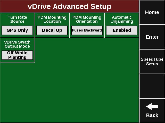
4 Illustration 3. Illustration _01 2/16 4

5 Illustration 5 2. The available settings on the SpeedTube Setup page are SpeedTube Auto-Unjam and SpeedTube Belt Overspeed as seen in illustration The default setting for Auto-Unjam is Enabled. When enabled, SpeedTubes will automatically reverse belt direction to clear a detected jam/obstruction. 4. The default value for SpeedTube Belt Overspeed is Disabled. This value should not be changed unless directed by Product Support. 5. Refer to the SeedSense Manual for general planter configuration/setup and vdrive Operation Manual for vdrive system setup. Swath Calibration Swath Run Cal cannot be performed with vdrive or SpeedTube installed. Operators should start with the default value for Start Seeding Offset and Stop Seeding Offset. It is recommended to dig for seeds, as the operator can make manual adjustments to the Start and Stop Seeding Offset values if needed. Confirm GPS offsets are correct before adjusting Start and Stop Seeding Offset values. Refer to Illustration _01 2/16 5
, SpeedTubes will operate at a minimum belt speed.")

6 Illustration 6 SpeedTube Operation SpeedTubes will operate anytime the Master Plant or a single Section Plant switch is active on the Cab Control Module. If the planter is not moving (lifted or lowered), SpeedTubes will operate at a minimum belt speed. To deactivate SpeedTube operation, the Master Plant and all three Section Plant switches must be off. Refer to illustration 7. Vacuum Setting Illustration 7 Increased vacuum is sometimes necessary when operating SpeedTube at higher speeds. This will help limit seeds from dropping off the disk (due to increased rough ride) before reaching the feeder wheels _01 2/16 6
 look ok, poor good ride will not impact performance. Operators should not limit speed based solely on Good Ride.")
7 Good Ride Metric Good Ride is of limited significance when SpeedTube is installed across the whole planter. As long as other planting metrics (spacing, SRI, ground contact, etc.) look ok, poor good ride will not impact performance. Operators should not limit speed based solely on Good Ride. The Smooth Ride Limit on the 20/20 and the Good Ride legend in FieldView can be adjusted as needed. SpeedTube Diagnostics When components are powered and communicating properly with the 20/20 SeedSense Monitor, modules will be green on the diagnose page. 1. Navigate to the SpeedTube Diagnose page by selecting Setup, Diagnose, SpeedTube. Refer to illustrations Illustration _01 2/16 7

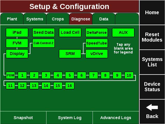
8 Illustration 9 Illustration _01 2/16 8
 Measure of SpeedTube belt speed and is the number of belt flights per second as detected by seed sensors.")
9 Illustration The SpeedTube Diagnostic page displays the following information for each row: Speed Source Will display current speed source GPS, Radar, or none. Actual FPS (Flights per Second) Measure of SpeedTube belt speed and is the number of belt flights per second as detected by seed sensors. Command FPS (Flights per Second) SpeedTube belt speed or flights per second as commanded. Stability Displays stability of SpeedTube motor. Supply Volts Voltage at SpeedTube Module. Drive Amps SpeedTube current draw in amps. Duty Cycle Displays SpeedTube motor output over the operating range. Seed Count Seeds detected on each row. SpeedTube Health Checks 1. After all components are detected and communicating properly, SpeedTube Health Checks should be performed. The Health Check page can be accessed from the SpeedTube Diagnostic page as shown in illustration 11, or directly from the Setup page as shown in illustration Select Voltage Current and follow the on-screen prompts for test requirements and to begin the test. Refer to illustrations 12 and _01 2/16 9
 equivalent to travelling")

10 Illustration 12 Illustration The health check will operate through three different sections. The initial section is a warmup period in which the SpeedTubes will operate at a FPS (or RPM) equivalent to travelling at 11 MPH. During the second section, the SpeedTubes will run at a FPS equivalent to 2.5 MPH. The final portion of the health check will operate the SpeedTubes at a FPS equivalent to 10 MPH. Data is collected during the 2.5 MPH and 10 MPH portions _01 2/16 10
11 4. Below are the failure thresholds for the health check: Voltage <10 volts Amperage 3.5 MPH Test: >0.5 Amps 11 MPH Test: >4.0 Amps Duty Cycle 3.5 MPH Test: >30% 11 MPH Test: >95% Stability 3.5 MPH Test: +/-6% 11 MPH Test: +/-3.5% 5. The results page will be red for rows which no information was received. The results page will be yellow for any value out of range. 6. In the event of a failed Health Check, reference the instructions listed below. Voltage Failure: There is low supply voltage. Check harnessing for damage and ensure alternator is operating. Amperage Failure: Ensure voltage is within range. Check for obstructions or misaligned parts in SpeedTube. Duty Cycle Failure: Check for obstructions or misaligned parts in SpeedTube. Note: If problems persist, refer to the SpeedTube Troubleshooting Guide for more detailed information _01 2/16 11


12 SpeedTube Cover and Belt Removal Note: The belt cover can be removed to gain access to the belt and other internal components for inspection, removal, and cleaning. 1. Remove the sensor transmitter using the hand knob. Move the sensor to the side. Refer to illustration 14. Illustration 14 Remove Sensor 2. Remove the SpeedTube belt cover. Push up on the belt cover near the sensor removed in step 1, while simultaneously releasing the lower cover retaining tab. Rotate the cover away from the SpeedTube belt housing. Refer to illustration 15. Push tab toward bottom of SpeedTube to release _01 2/16 12


13 Illustration 15 Removal of Belt Cover 3. Remove the belt by rotating it by hand and rolling it off the bottom idler pulley. Remove from the top drive pulley. 4. Re-install the belt by placing it around the top drive pulley. Ensure it is fully seated. Rotate the belt by hand and roll it onto the bottom idler pulley. Rotate the belt back and forth to check alignment and smooth operation. Note: When Re-installing the belt, take notice of the flight orientation. Reference the diagram molded into the SpeedTube housing for correct orientation. Refer to illustration 16. Illustration 16 Belt Orientation 5. To re-set the tension for the new belt, loosen the tension bracket retaining screw and ensure the bracket is free from debris and can move freely. Refer to illustration 17. Illustration 17 Loosen Tension Bracket Retaining Screw _01 2/16 13


 Note: Meter crop kits will also need to be changed")
14 6. Roll the belt back and forth by hand. The coil spring will provide the appropriate tension to the belt. Re-tighten the tension bracket retaining screw. 7. Re-install the belt cover. Confirm the hook on the bottom of the cover is inserted in the latch on the belt housing as shown in illustration 18. Press the cover down around the lower retaining clip. A click should be heard, confirming the cover is secured to the housing. Reinstall the sensor. Illustration 18 Install SpeedTube Belt Cover SpeedTube Crop Change (Corn to Soybeans) Note: Meter crop kits will also need to be changed when switching crops. 1) Install the soybean deflector by snapping it into the cavity on the gearbox housing. The small feeder wheel will stay installed. Refer to illustration 19. Illustration 19 Soybean Deflector Installation _01 2/16 14

15 2) To switch back to corn, simply remove the soybean deflector. Refer to illustration 20. Illustration 20 Soybean Deflector Removal Converting between a SpeedTube and a Seed Tube Note: To plant crops other than corn and soybeans it is necessary to re-install a seed tube. 1) Remove the meter from the hopper. 2) Separate the meter housing from the SpeedTube ready seed cover. 3) If necessary, transfer crop kit components from the SpeedTube seed cover to the Seed Tube seed cover. Refer to the vset 2 crop setup guide for more information. 4) Install a vset 2 seed tube seed cover on the meter housing and re-install the complete meter onto the hopper. 5) Remove the SpeedTube and SpeedTube retention spring from the row unit. 6) Re-install the seed tube. Note: Illustration 21 displays the difference between a vset 2 SpeedTube seed cover and a seed tube seed cover. Refer to the vset 2 manual for more details _01 2/16 15


 Details below.")

16 Seed Tube Seed Cover SpeedTube Seed Cover Illustration 21 vset 2 Meter Seed Covers Annual Maintenance Below is a list of items that should be checked on an annual basis. Details on when to replace components are also included. Take out belt and leave removed during off season. Reset belt tension before next planting season. Check feeder wheels for wear and replace as necessary. Details below. Check belt housing insert for wear and replace as necessary. Details below. Inspect overall SpeedTube for any damage or increased wear (housing, cover, sensor lenses, belt pulleys, etc.) Details below. Check opening disks and guards for accelerated wear or damage. It is best practice to replace guard when replacing opening disks. If power washing the planter at end of season, it is recommended to first remove SpeedTubes. Compressed air or lower pressure water is recommended for cleaning SpeedTubes. Check row unit for any loose hardware, specifically parallel arm fasteners _01 2/16 16


17 Feeder Wheel Wear Grove worn in feeder wheels on side closest to seed disk Should be replaced if seeding performance is negatively affected New, unworn feeder wheels Broken feeder wheel fingers Should be replaced _01 2/16 17


18 SpeedTube Housing Insert Wear New housing insert (top) vs. worn housing insert (bottom) Replace when bumps are worn down/broken off New insert installed in housing Drive Pulley Wear New drive pulley _01 2/16 Worn drive pulley Should be replaced 18


 vs.")
 955424_01 2/16")
19 SpeedTube Cover and Housing Wear Material starting to wear and thin wall thickness New cover and housing Worn cover and housing Should be replaced SpeedTube Drive Housing Insert New Drive Housing Insert (left) vs. Worn/Damaged Insert (right) _01 2/16 New Drive Housing Insert Installed 19

20 SpeedTube Guard Wear New SpeedTube Guard Worn SpeedTube Guard Replace on same schedule as opening disks, unless wear develops faster as shown Troubleshooting Please refer to the SpeedTube troubleshooting guides available on the Technical Documents portion of the Precision Planting Website _01 2/16 20
955424_2 6/13/2018. SpeedTube Operator s Guide For Gen 2 20/20 Displays
 955424_2 6/13/2018 SpeedTube Operator s Guide For Gen 2 20/20 Displays Contents SpeedTube Setup...3 SpeedTube Operation...4 SpeedTube Diagnostics...5 SpeedTube Health Checks...6 955424_2 6/13/2018 2 SpeedTube
John Deere ME5 Row Unit Kit Installation Manual Kit Number
 John Deere ME5 Row Unit Kit Installation Manual Kit Number 768503 955422_01 11/15 1 System Hardware Part Number Description Quantity 768503 John Deere ME5 SpeedTube Row Unit Kit 1 per row The Row Unit
Cam Handle Service Guide
 Cam Handle Service Guide Page 2. Introduction Page 3. Troubleshooting guide Page 4-5. Adjusting the clamp force Page 6-7. Disassembling, greasing and replacing components Page 8-9. Replacing the post bearings
Electric Skein Winder
 Electric Skein Winder Assembly and Use Package Contents 1 - Triangular Body (w/ motor) 1 - Cross Arm 1 - Left Foot (w/ yarn guide) 1 - Right Foot 1 - Adjustable Finger (w/ yarn clip) 3 - Adjustable Fingers
TS- Feedback Sweep Motor Error
 Step Description Picture Machine gives the message Feedback Sweep Motor upon start up. During gameplay the machine stopped and said Feedback Sweep Motor. Reasons for this message could be: 1. There is
The Bowflex Revolution XP Home Gym Assembly Instructions. P/N: Rev ( /0 )
") P/N: 001-7057 Rev ( /0 ) The Bowflex Revolution XP Home Gym Assembly Instructions 2 Table of Contents Before You Start... 2 Tools You Will Need / Hardware Contents... 3 Box Contents... 6 Assembling Your
P/N: 001-7057 Rev ( /0 ) The Bowflex Revolution XP Home Gym Assembly Instructions 2 Table of Contents Before You Start... 2 Tools You Will Need / Hardware Contents... 3 Box Contents... 6 Assembling Your
SAFETY TIPS. Always unplug the Revolution XT from its power source before removing it from the water bath or when performing any maintenance.
 SAFETY TIPS Always unplug the Revolution XT from its power source before removing it from the water bath or when performing any maintenance. Always wear safety glasses when the saw is in operation. NEVER
Senior Swing. Caution
 *740132* 740132 2800 Overhead Concealed Series 9500 Surface Applied Series Senior Swing Installation Instructions Caution LCN Senior Swing The Senior Swing Power Operator System is a low energy product
Motorized or Crank Operated Fortress Zipper Track Shade with Housing and Side Track Installation Instructions
 Motorized or Crank Operated Fortress Zipper Track Shade with Housing and Side Track Installation Instructions Tools Needed Drill 3/8 Metal Drill Bit ¼ Masonry Drill Bit Measuring Tape Pencil 4 Level Phillips
7878 K940. Checkpoint Antenna. Kit Instructions. Issue B
 7878 K940 Checkpoint Antenna Kit Instructions Issue B Revision Record Issue Date Remarks A July 7, 2009 First issue B Nov2013 Revised the Checkpoint installation procedures for 7878 and 7874 scanners Added
Replacing the Reciprocator on the SWF Compact Series Machine (601C and 1201C)
") Follow the instructions below to replace the reciprocator in the SWF Compact series machines. The tools required can be found in the tool kit that came with the machine. Preparation 1. First, place the
Follow the instructions below to replace the reciprocator in the SWF Compact series machines. The tools required can be found in the tool kit that came with the machine. Preparation 1. First, place the
HAPPY HCS Voyager: Level-1 Maintenance & Repair Intermediate-level repair / maintenance procedures
 TEXMAC Inc. HAPPY HCS Voyager Introduction Training page 1 HAPPY HCS Voyager: Level-1 Maintenance & Repair Intermediate-level repair / maintenance procedures Table of Contents Oiling/Cleaning Page 2 Removing
SAVE THIS FOR FUTURE REFERENCE THIS PRODUCT IS FOR PROFESSIONAL LABORATORY USE ONLY USER'S MANUAL
 DENTAL, INC. TECHNICAL BULLETIN G801-022510 5860 FLYNN CREEK ROAD READ ALL INSTRUCTIONS P.O. BOX 106 BEFORE PROCEEDING COMPTCHE, CALIFORNIA, U.S.A. 95427-0106 SAVE THIS FOR FUTURE REFERENCE www.wellsdental.com
FBX-PA-2AC. Third edition : April No
 FBX-PA-2AC Third edition : April 2006 No. 060058 INTRODUCTION Thank you very much for purchasing Kansai Special FBX series. Read and study this Instruction Manual carefully before you start any of the
Removing the Z-Axis lead screw
 Page 1 of 8 TITLE: Sabre Z-Axis Lead Screw Replacement Procedure Gerber FastFact #: 5048 Supplied by: Gerber Hardware Support Last Modified: June 14, 2007 Summary: Tools used: The following procedure explains
Chapter 4: Troubleshooting and Maintenance
 Training: HAPPY HCD-1501 Operations & Maintenance Chapter 4: Troubleshooting and Maintenance Basic Troubleshooting/ Sewing Interruptions Troubleshooting thread breaks 2 Maintenance and Upkeep Oiling: daily
Service Manual for XLE/XLT Series Laser Engravers
 Service Manual for XLE/XLT Series Laser Engravers Table of Contents Maintenance...1 Beam alignment...3 Auto focus alignment...8 Bridge alignment...10 Electronics panel replacement...11 X motor change...12
Be sure any accessory used will fit with the soft upper doors before installing. Not all accessories will be compatible.
 Company Name: Spike Power Sports Vehicle Name: Polaris General 2P Product Description: Soft Upper Doors Part Number: 58-1600 Revision: R01 09/19/2018 Contents: 655 Elm Ridge Ave, Canal Fulton OH, 44614
FBX1104P FBX1104 FBX1106P FBX1106
 FBX1104P FBX1104 FBX1106P FBX1106 Second edition : September 2004 No. 040037 INTRODUCTION Thank you for your purchasing Kansai Special's FBX Series. Read and study this instruction manual carefully before
Removing and Replacing the Y-truck
 Service Documentation Removing and Replacing the Y-truck To remove and replace the Y-truck you will need the following tools: 4mm Allen wrench 12mm stamped flat wrench #2 Phillips screwdriver (magnetic
Astro-Physics Inc. 400QMD Lubrication/Maintenance Guide
 Astro-Physics Inc. 400QMD Lubrication/Maintenance Guide The following guidelines should be followed to lubricate the three main parts of the 400QMD mount. The QMD stands for Quartz Micro-Drive controller.
С 800 CASSIDA C 800 HIGH SPEED COIN COUNTER
 С 800 CASSIDA C 800 HIGH SPEED COIN COUNTER This manual contains important information on safety measures and operational features. Please read it carefully before operating your coin counter, and keep
Safety Instructions, Installation & Operator's Manual For. # CLAMSHELL GRASS CA TCHER KIT For 28" & 33" REAR ENGINE RIDING MOWERS
 Safety Instructions, Installation & Operator's Manual For #6-3125 CLAMSHELL GRASS CA TCHER KIT For 28" & 33" REAR ENGINE RIDING MOWERS 28" REAR ENGINE RIDER WITH CLAMSHELL BAGGER KIT SHOWN SNAPPER, McDonough,
ABM International, Inc.
 ABM International, Inc. Lightning Stitch required 1 1.0: Parts List head and motor assembly (Qty. 1) Reel stand (Qty. 1) Needle bar frame clamp (Qty. 1) Motor drive (Qty. 1) 2 Cable harness with bracket
Procedure, Field Replacement, PCU Kit, XX04
 1. Brief Summary: Troubleshooting document for diagnosing a fault with and replacing the XX04 series PCU assembly. 2. Checklist: Verify Initialization N0 Parameter Pedestal Error Test Motor 3. Theory of
SAVE THIS FOR FUTURE REFERENCE THIS PRODUCT IS FOR PROFESSIONAL LABORATORY USE ONLY USER'S MANUAL
 DENTAL, INC. TECHNICAL BULLETIN Q827-022510 5860 FLYNN CREEK ROAD READ ALL INSTRUCTIONS P.O. BOX 106 BEFORE PROCEEDING COMPTCHE, CALIFORNIA, U.S.A. 95427 SAVE THIS FOR FUTURE REFERENCE www.wellsdental.com
APES HD-7700 Version Operator s Training Manual
 APES-14-77 HD-7700 Version Operator s Training Manual Issue A1 09/03 P/N 900599 Performance Design Inc. 2350 East Braniff St. Boise Idaho 83716 This manual contains very important safety information and
ABM International, Inc. Navigator Assembly Manual
 ABM International, Inc. 1 1.0: Parts List Tablet (Qty. 1) Tablet mount (Qty. 1) NOTE: Mount may appear and operate different then image below Control Box (Qty. 1) Motor Power Supply (Qty. 1) 2 X-axis motor
Heavy Duty Ceiling Tilt Mount Installation Manual
 HD-CTM-5580 Heavy Duty Ceiling Tilt Mount Installation Manual *This Installation requires a minimum of two people. For your safety: Read the complete instruction manual before starting an installation
Powermatic Model 31A Combination Belt-Disk Sander
 OPERATING PROCEDURE FOR: Powermatic Model 31A Combination Belt-Disk Sander INTRODUCTION: The combination belt-disk sander is used to sand the edges of boards. It can be used to smooth the edge or to remove
Replacing the Reciprocator on an SWF Multi-head.
 Replacing the Reciprocator on an SWF Multi-head. Follow the instructions below to replace the reciprocator in the SWF multi-head machines. The tools required are found in the tool kit that came with the
BL500 Series Brake Lathes Variable and Single Speed Combination Lathes. Change from servicing rotors to drums in seconds!
 BL500 Series Brake Lathes Variable and Single Speed Combination Lathes Change from servicing rotors to drums in seconds! BL505 Combination Brake Lathe 11 9 10 1 4 2 BL505 shown with optional Digi-Cal Auto
Band-Master ATS Nano Pneumatic Banding Tool Operating Instructions
 Band-Master ATS 601-118 Nano Pneumatic Banding Tool CONTENTS 601-118 Overview... 3 Safety.... 5 Initial Tool Set-up... 5 Regulator assembly mounting... 5 Attach tool head to regulator.... 6 Operating instructions...
AutoSeal FD 1506 Plus / FE 1506 Plus
 AutoSeal FD 1506 Plus / FE 1506 Plus FK / FL SERIES 06/2018 OPERATOR MANUAL FIRST EDITION TABLE OF CONTENTS DESCRIPTION 1 UNPACKING AND SET-UP 2 CONTROL PANEL 3 OPERATION 3 FOLD PLATE ADJUSTMENT 4 SETTING
MK-7 Maintenance Manual Revision3 (Ver R02)
") MK-7 Maintenance Manual Revision3 () 1. Features ------------------------------------------------------------------------------------ P2 2. Components -------------------------------------------------------------------------------
MK-7 Maintenance Manual Revision3 () 1. Features ------------------------------------------------------------------------------------ P2 2. Components -------------------------------------------------------------------------------
FD 125 Large-Format Card Cutter
 FD 125 Large-Format Card Cutter 3/201 OPERATOR MANUAL Page 2 Table of Contents SAFETY PRECAUTIONS... 4 Introduction... 5 Specifications... 5 Accessories... 5 Major Components and Assemblies... 6 Control
Field Service Procedure Level Cage Motor Kit, 2406
 1. Brief Summary: Troubleshooting document for diagnosing a fault with and replacing the level cage motor on the 2406 antenna. 2. Checklist: Verify Initialization Verify Pointing Verify Targeting 3. Theory
TABLE OF CONTENTS DESCRIPTION. Safety Instructions Assembly Operation... 7
 TABLE OF CONTENTS DESCRIPTION PAGE Warranty... 1 Safety Instructions... 2 Assembly... 3 Operation... 7 #360 Grain Cleaner Drawings... 8 #360 Grain Cleaner Parts List... 10 Utility Auger Option Drawing...
Sink BULL INSTRUCTION MANUAL. with Rapid Z -CUT & Rapid Z -DRUM
 Sink BULL with Rapid Z -CUT & Rapid Z -DRUM INSTRUCTION MANUAL Please read this instruction manual thoroughly to ensure safety and the correct use of this tool. Keep this manual in a place where operators
Easy Engineering Guide
 Index: Unleash Your Creativity! Page 1: The Basics Page 2: Sorting Dowels Page 3: Measuring and Cutting Page 4: Dowels and Holes (Reaming Holes) Page 5: Reaming, Screws, Slide-Stop Material Page 6: Hydraulics/Pneumatics
i1800 Series Scanners
 i1800 Series Scanners User s Maintenance Guide A-61555 6J7418 5 Maintenance This chapter provides: a cleaning frequency chart a list of cleaning tools and materials a list of supplies, consumables and
Field Service Procedure PCU Kit, XX97, XX97A & XX00
 1. Brief Summary: Troubleshooting document for diagnosing a fault with and replacing the PCU assembly on the XX97, XX97A and XX00 series antennas. 2. Checklist: Verify Initialization N0 Parameter Pedestal
Slitter/E-Prom Upgrade for Duplo CC-228
 This Service Bulletin covers the upgrade of the Post Card Slitter and E-Prom for the Duplo CC-228 machines at Staples locations nationwide. Be sure to review and follow ALL of these instructions. Failure
Owner s Maintenance Section
 Owner s Maintenance Section Table of Contents Heavy Duty 1. Arm Loosening 2. Weather Changes & Closing Speed Adjustments 3. Door Out of Plumb Offset 4. Door Out of Plumb Center Hung 5. Door Sagging Vertical
MS25 OPERATION MANUAL
 SAFETY INSTRUCTIONS SPECIFICATIONS OPERATING INSTRUCTIONS MAINTENANCE ADJUSTMENTS REPLACEMENT OF PARTS MS25 DIAGRAM MS25 PARTS LIST MS25 OPERATION MANUAL SAFETY INSTRUCTIONS Please read these instructions
Electronically Commutated (EC) Motor Control with Solo, Select and Sync PWM Boards
 Motor Control with Solo, Select and Sync PWM Boards") Electronically Commutated (EC) Motor Control with Solo, Select and Sync PWM Boards The Solo, Select and Sync PWM boards provide a pulse-width modulated (PWM) signal to the EC motor to control fan speed.
Electronically Commutated (EC) Motor Control with Solo, Select and Sync PWM Boards The Solo, Select and Sync PWM boards provide a pulse-width modulated (PWM) signal to the EC motor to control fan speed.
ITEM NO. PART NO DESCRIPTION QTY.
 PUMP MAINTENANCE ITEM NO. PART NO DESCRIPTION QTY. 1 52002 Center Case 1 2 52052 Back End Plate 1 3 52051 Front End Plate 1 4 55090 Octagonal Nut 1 5 53001 Idler Gear 1 6 53002 Drive Gear 1 7 28062 Bushing
Spinnit FMM3 Paper Drill
 Spinnit FMM3 Paper Drill Instruction Manual Provided By http://www.mybinding.com http://www.mybindingblog.com Before operating this equipment, please read these instructions completely and keep these operating
PROFESSIONAL FLARING TOOL 001ERL 37 & ERL 37
 PROFESSIONAL FLARING TOOL 001ERL 37 & 45 002ERL 37 001ERL shown here OWNER S MANUAL 199R11215 EDUCATIONAL TIPS Make sure the end of the tube is cut off square. Before flaring, make sure the die clamp is
Basic Spring Motor Roller Shades
 Basic Spring Motor Roller Shades ATTENTION!!! READ CAREFULLY! This shade has a reliable long-lasting Spring Motor. The Spring Motor must have proper tension in order to function as intended. Handling in
INSTALLATION & OWNER S MANUAL
 Rev. D, p. 1 of 15 INSTALLATION & OWNER S MANUAL Polaris Ranger (2009-) Tapered UTV Poly Plow with Vehicle Mount Kit 6 Wide Snow Plow (p/n: 1POLUTP) (fits the 500 H.O., 700 & 800 HD & XP) The contents
Page 1. SureMotion Quick-Start Guide: LACPACC_QS 1st Edition - Revision A 03/15/16
 R K C T I Repair Kit Product Compatibility Repair Kit # Linear Actuator Assembly # LACPACC-002 LACPACC-003 LACP-16TxxLP5 (0.5-in lead screw pitch) LACP-16TxxL1 (1-in lead screw pitch) C P I R K 4 ea Flanged
Procedure 5: Hammer Bank Removal
 T6215 Maintenance Manual Procedure 5: Hammer Bank Removal The Hammer Driver CBA has components which are static sensitive! Use the appropriate ESD grounding procedures when handling the Hammer Bank Assembly.
OPERATION & MAINTENANCE MANUAL
 OPERATION & MAINTENANCE MANUAL AUTOMATIC PECAN CRACKER Food Processing Equipment and Machinery Specializing in the Pecan Industry Mailing: PO Box 817, Mansfield, Louisiana 71052 Located: 280 Independence
Nancy s Knit Knacks LLC 4 Yard Option Upgrade Kit Assembly Instructions and User Manual
 Nancy s Knit Knacks LLC 4 Yard Option Upgrade Kit Assembly Instructions and User Manual Thank you for purchasing our 4 Yard Option (4YO) Upgrade Kit. To install this upgrade you are simply going to assemble
ROMAN AND. Roller Lift System Continuous Cord Loop GETTING STARTED BRACKET INFORMATION INSIDE MOUNT. A few simple tools are required:
 ROMAN AND WOVEN WOOD SHADES Roller Lift System Continuous Cord Loop GETTING STARTED BRACKET INFORMATION A few simple tools are required: The brackets you received with your product are REQUIRED for proper
OWNER S MANUAL. Safety. Please read this owner s manual before use and keep it at hand for reference. Warranty
 Please read this owner s manual before use and keep it at hand for reference. OWNER S MANUAL Safety Important safety instructions for using the INCRA Miter5000 Before using the INCRA Miter5000, read and
Screwfeeder Troubleshooting Guide
 Symptom General Cause Specific Cause Solution Illustration No Screws are being fed to the screwdriver Screw jam in screw delivery tubing Insufficient Screw Blast to deliver screw Adjust Screw Blast Inline
HOW TO MEASURE AND FIT REPLACEMENT TRUNNION ROLLERS
 HOW TO MEASURE AND FIT REPLACEMENT TRUNNION ROLLERS When Customers order trunnion rollers for their Double Arm (DA) mixers they may not be aware that these rollers need to be custom fit to their mixer.
Procedure, Field Replacement, PCU Kit, 6003A/6004, 2406 & 4003A
 1. Brief Summary: Troubleshooting document for diagnosing a fault with and replacing the PCU assembly on the 6003A/6004, 2406 & 4003A series antennas. 2. Checklist: Verify Initialization N0 Parameter Pedestal
INSTRUCTION MANUAL AND PARTS LIST MODEL 14-10
 VERTICAL BAND SAWS INSTRUCTION MANUAL AND PARTS LIST MODEL 1-10 DAKE/PARMA WHEN ORDERING PARTS GIVE COMPLETE SERIAL NUMBER OF MACHINE GIVE PART NUMBER AND NAME GIVE AMOUNT REQUIRED Unless the above data
INSTALLATION INSTRUCTIONS DODGE RAM 2 & 4WD 1500 PART # P5058
 INSTALLATION INSTRUCTIONS 2009-13 DODGE RAM 2 & 4WD 1500 PART # P5058 PARTS LIST: Qty Description Qty Description 1 Grille Guard 12 12-1.75mm Hex Nuts 2 Upper Frame Mounting s (for trucks without tow hooks
Post-Installation Checkout All GRT EFIS Models
 GRT Autopilot Post-Installation Checkout All GRT EFIS Models April 2011 Grand Rapids Technologies, Inc. 3133 Madison Avenue SE Wyoming MI 49548 616-245-7700 www.grtavionics.com Intentionally Left Blank
HOME GYM Owner s Manual
 HOME GYM Owner s Manual Content Content-------------------------------------------------------------1 Safety precautions----------------------------------------------------2 Assembly instruction-------------------------------------------------3-12
eset Standard Installation Instructions
 720242, 745021, 745022 eset Standard Installation Instructions Parts included: 1. 2. 3. 4. 5. 6. 7. 8. 9. 10. 11. 12. 13. 14. 1. 2. 3. Complete eset Kit, (720134) Disk, (1) Liner, (1) Singulator, (1) Long
INSTALLATION INSTRUCTIONS GRILLE GUARD RAM 1500 PART # 5058/5058-2
 INSTALLATION INSTRUCTIONS GRILLE GUARD PART # 5058/5058-2 PARTS LIST: Qty Description Qty Description 1 Grille Guard 8 12-1.75mm x 35mm Hex Bolts 2 Upper Frame Mounting s (for trucks without tow hooks
Deluxe Exterior Solar Shades
 Deluxe Exterior Solar Shades Installation Instructions Email: customerservice@blindster.com Call us: (888) 256-8672 Mon - Fri 8am - 7pm (CT) Thank you for purchasing Deluxe Exterior Solar Shades from Blindster.
ATV STORM CHASER PLOW PUSH TUBE KIT
 ATV STORM CHASER PLOW PUSH TUBE KIT P/N 33-0070 OWNER S MANUAL Application MID-BODY ATV MOUNT NO. 15-XXXX, ALL MOUNT NO. 15-0050 ATTENTION DEALER: CUSTOMER MUST RECEIVE A COPY OF THIS MANUAL AT THE TIME
FUNCTIONAL DESCRIPTION
 FUNCTIONAL DESCRIPTION NOTE: The information contained in this Instruction Manual is designed to assist you in the safe operation and maintenance of the power tool. Some illustrations in this Instruction
Contemporary 3 Panel Classic 5 Panel French Panel
 Contemporary 3 Panel Classic 5 Panel French Panel (X) Operating / Lock Panel Left (O) Fixed Panel Right Note : Glazing Beads For All Panel Face To The Exterior 2 Panel XO Left Is Shown Above Opposite =
VYTEX PREMIUM SLIDING GLASS DOOR. Table of Contents. Precautions and Safety 2. Tools Required...3. Inspect and Prepare Door...4
 VYTEX PREMIUM SLIDING GLASS DOOR Table of Contents Precautions and Safety 2 Tools Required...3 Inspect and Prepare Door...4 Hardware and Parts Check List....4 Master Frame Assembly 5 Master Frame Installation..7
INSTALLATION & OWNER S MANUAL
 Rev. O p. 1 of 16 INSTALLATION & OWNER S MANUAL V4213 BALL CAGE KIT INSTALLATION & OWNER S MANUAL The contents of this envelope are the property of the owner. Be sure to leave with the owner when installation
TABLE OF CONTENTS DESCRIPTION. Safety Instructions Assembly Operation... 7
 TABLE OF CONTENTS DESCRIPTION PAGE Warranty... 1 Safety Instructions... 2 Assembly... 3 Operation... 7 #360 Grain Cleaner Drawings... 8 #360 Grain Cleaner Parts List... 10 Utility Auger Option Drawing...
ACCESS COVER INSTALLATION INSTRUCTIONS (Kit #601 for 2006 Honda Ridgeline)
") ACCESS COVER INSTALLATION INSTRUCTIONS (Kit #601 for 2006 Honda Ridgeline) NOTE TO INSTALLER: IMPORTANT READ BEFORE ATTEMPTING INSTALLATION. Allow extra time, up to 2 hours to install this cover. Disassembly
ACCESS COVER INSTALLATION INSTRUCTIONS (Kit #601 for 2006 Honda Ridgeline) NOTE TO INSTALLER: IMPORTANT READ BEFORE ATTEMPTING INSTALLATION. Allow extra time, up to 2 hours to install this cover. Disassembly
Referencing 0,0 position
 Page 1 of 11 TITLE: SABRE X-Axis Lead Screw Replacement Procedure Gerber FastFact #: 2013 Supplied by: Gerber Hardware Support Last Modified: March 1, 2011 Summary: The following procedure explains how
Pow-R-Feed Systems Service Manual
 Pow-R-Feed Systems Service Manual Important Safety Instructions Please read this manual carefully and follow its instructions. Improper use or failure to follow these instructions could result in serious
INSTALLATION INSTRUCTIONS for the JOMY RETRACTABLE LADDER. If there are any questions, please call (800)
") INSTALLATION INSTRUCTIONS for the JOMY RETRACTABLE LADDER If there are any questions, please call (800) 255-2591 INSTALLATION INSTRUCTIONS WARNING! Ladder Sections Lock When Closed. Do Not Install or Close
INSTALLATION INSTRUCTIONS for the JOMY RETRACTABLE LADDER If there are any questions, please call (800) 255-2591 INSTALLATION INSTRUCTIONS WARNING! Ladder Sections Lock When Closed. Do Not Install or Close
INSTALLATION GUIDE 2009-CURRENT HUMMER H3T PRODUCT CODE:
 INSTALLATION GUIDE 2009-CURRENT HUMMER H3T PRODUCT CODE: 268 June 22, 2010 TOOLS NEEDED COMPONENTS INCLUDED P2 Tip 3/8" Drill Rubber Gasket(s) x 2 Bracket(s) x 2 1/2" Drill Bit Bulkhead Flange #2 Phillips
CNC Using the FlexiCam CNC and HMI Software. Guldbergsgade 29N, P0 E: T:
 CNC Using the FlexiCam CNC and HMI Software Guldbergsgade 29N, P0 E: makerlab@kea.dk T: +46 46 03 90 This grey box is the NC controller. Let s start by turning the red switch to the ON position, then press
Print Head Installation Guide
 Print Head Installation Guide MCS Raptor 6 (MCS Eagle AMS Software) is copyright of MCS Incorporated. 2015 MCS Incorporated. 1 Contents Tools... 4 Warnings... 4 Introduction... 4 Section One - Pillar Installation...
C a r r i a g e A s s e m b l y R e p l a c e m e n t
 E1 TF-CR C a r r i a g e A s s e m b l y R e p l a c e m e n t October 2007 Software Version 5.0 and higher IMPORTANT! TigerStop must be enabled with a code that must be obtained from TigerStop Customer
V-Groover SIMPLEX INSTRUCTION AND OPERATION MANUAL M O DEL 703. For best results use only authentic Logan blades.
 www.logangraphic.com SIMPLEX M O DEL 703 INSTRUCTION AND OPERATION MANUAL For best results use only authentic Logan blades CAUTION: BLADES EXTREMELY SHARP Use replacement blades #1258 Logan Graphic Products,
PULL-THRU USER S MANUAL
 PULL-THRU USER S MANUAL G14x Part # 310 120 177 G20 Part # 310 120 188 G20x Part # 310 120 186 G40x Part # 310 120 163 TABLE OF CONTENTS SECTION 1 PCB DESIGN AND MOUNTING SECTION 2 MOUNTING ADAPTER TO
TABLE OF CONTENTS DRAWINGS
 TABLE OF CONTENTS Bifold Door Adjustment Procedures...pg 4 Bifold Door Maintenance...pg 6 Safety Concerns...pg 9 Troubleshooting...pg 10 Bifold Door Maintenance Checklist...pg 11 DRAWINGS EK 1880 Bifold
WPS crew Doors Installation instructions
 WPS-132-133 crew Doors Installation instructions ORDER OF INSTALLATION FOR A COMPLETE ENCLOSURE OF A CREW WPS (Weather Protection System) IS AS FOLLOWS: 1. Heater 2. Rear Thresholds - Right Hand & Left
15MM LINEAR MOTION SYSTEM
 222fg 15MM LINEAR MOTION SYSTEM September 20, 2017 15mm Linear Motion System Copyright 2017 REV Robotics, LLC 1 TABLE OF CONTENTS 1 INTRODUCTION... 3 2 ASSEMBLY INSTRUCTIONS... 4 3 How to drive Linear
BL500 Series Brake Lathes
 BL500 Series Brake Lathes Variable and Single Speed Combination Lathes Form 3937T, 04/04 Supersedes 3937T, 05/02 Change From Rotors to Drums in Seconds! BL505 Combination Brake Lathe 11 9 10 1 4 2 BL505
45 CUTTING HEAD TILE SAW-BLADE ALIGNMENT PROCEDURE
 The of the MK-770 may become misaligned with the Cutting Head of the Tile Saw over time. Should misalignment occur, perform the following steps to realign the Tile Saw. NOTE: If alignment problems are
Castle Frame Assembly Table AT-8. Diagnostics Manual. Castle, Inc. Petaluma, CA
 Castle Frame Assembly Table AT-8 Diagnostics Manual Castle, Inc. Petaluma, CA 800-282-8338 Solutions Index Adjusting the Tabletop.. 8.01 Adjusting the Fence... 8.02 Aligning the Arm... 8.10 Adjusting Bracket..
OWNERS MANUAL. Model No LB. POLY PRO SPIKER/SPREADER. CAUTION: Read Rules for Safe Operation and Instructions Carefully
 OWNERS MANUAL Model No. -0301 CAUTION: Read Rules for Safe Operation and Instructions Carefully 17 LB. POLY PRO SPIKER/SPREADER Safety Assembly Operation Maintenance Parts PRINTED IN U.S.A. FORM NO. 78
30DC Speed Lathe Manual
 30DC Speed Lathe Manual The Crozier Model 30DC Speed Lathe is our most popular model. It has many standard features not found on any other machine in its class or price range. Standard Features 3/4 HP
OPERATIONS MANUAL. Port-O-Slitter
 Tapco Products Company The World Leader in Specialty Tools for the Professional Port-O-Slitter OPERATIONS MANUAL General instructions, set up, accessories and guide to using your portable precision slitting,
N. 15th Street, Middlesboro, KY FLIP TARP DUMP BODY INSTALLATION INSTRUCTIONS
 1-800-248-7717 1002 N. 15th Street, Middlesboro, KY 40965 FLIP TARP DUMP BODY INSTALLATION INSTRUCTIONS Congratulations on your purchase of a Mountain Flip Tarp Dump Body tarping system. With tarping systems
Elimination of Elevator Bounce
 For the Agilent Archon Autosampler Rework Instructions CAUTION This kit is intended for use by Agilent Service personnel only. Elevator Removal 1 Open top cover. 2 Open front lower door. 3 Remove vial
RH-412 STEEL DOORS INSTALLATION INSTRUCTIONS
 RH-412 STEEL DOORS INSTALLATION INSTRUCTIONS By following the steps outlined below, the assembly, installation and adjustment of the steel doors, will be a simple process. Let s start with the Driver Side.
1. Turn off or disconnect power to unit (machine). 2. Push IN the release bar on the quick change base plate. Locking latch will pivot downward.
. 2. Push IN the release bar on the quick change base plate. Locking latch will pivot downward.") Figure 1 Miniature Quick Change Applicators, of the end feed type, are designed to crimp end feed strip terminals to prestripped wires. Each applicator is set up to accept the strip form of certain specific
Figure 1 Miniature Quick Change Applicators, of the end feed type, are designed to crimp end feed strip terminals to prestripped wires. Each applicator is set up to accept the strip form of certain specific
Part # 4463 & Ford Mustang C-Series Upper & Lower Grilles
 Rev. 3/18 Page 1 Part # 4463 & 4464 2018 Ford Mustang C-Series Upper & Lower Grilles Notice: Install new, parts according to these instructions! Altered Parts are Non-Refundable! Part #4464 Notice: Part
REEL BLADE / BED KNIFE ADJUSTING & SHARPENING
 Here s a QR code image that can be used to access this document on a portable device. Reel Mower Cutting Fundamentals The reel mower s cutting ability is the result of the corner edges of the reel blade
WARNING. Read and become familiar with this manual BEFORE operating unit.
 Covered by one or more of the following patents: 3,828,942 5,368,429 5,586,619 5,984,605 7,556,464 7,726,901 Other patents pending. OPERATOR S MANUAL For Model 439 WARNING Read and become familiar with
SALES CUSTOMER SERVICE TECHNICAL ASSISTANCE CALL TOLL-FREE:
 DENTAL, INC. TECHNICAL BULLETIN U802-022510 5860 FLYNN CREEK ROAD READ ALL INSTRUCTIONS P.O. BOX 106 BEFORE PROCEEDING COMPTCHE, CALIFORNIA, U.S.A. 95427 SAVE THIS FOR FUTURE REFERENCE THIS PRODUCT IS