PROFESSIONAL FLARING TOOL 001ERL 37 & ERL 37
|
|
|
- Alban Ramsey
- 5 years ago
- Views:
Transcription


1 PROFESSIONAL FLARING TOOL 001ERL 37 & ERL ERL shown here OWNER S MANUAL 199R11215

. Use annealed stainless steel tubing.")
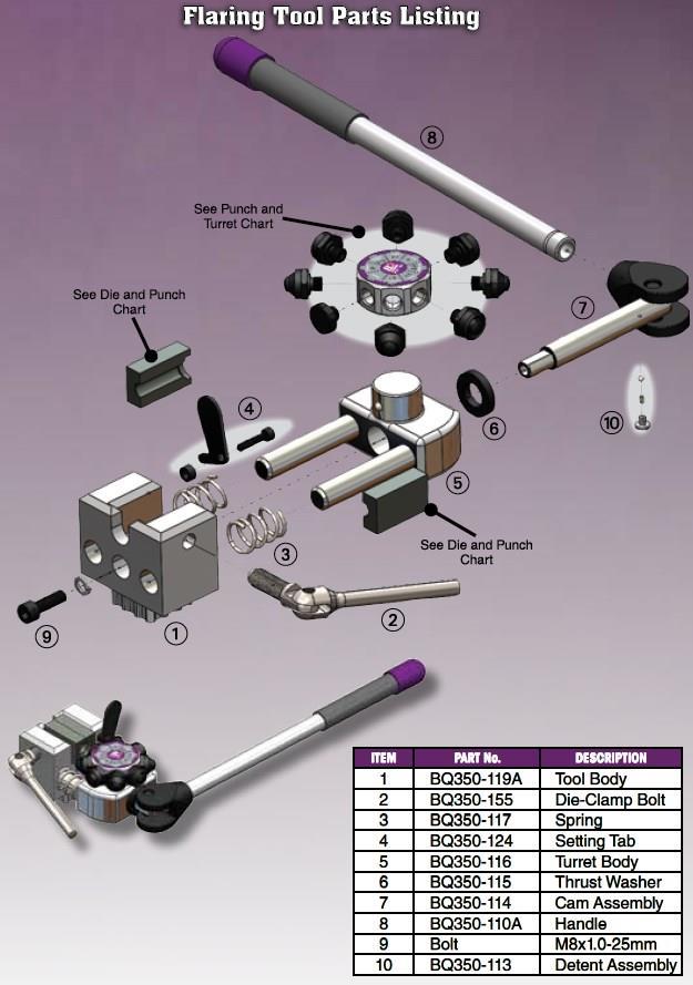
2 EDUCATIONAL TIPS Make sure the end of the tube is cut off square. Before flaring, make sure the die clamp is tight. Remember to add the tube nuts before shaping the tube or performing the final flare. Remember to add any spring guards before performing the final flare. Adding a drop of lubricating oil to the tube end before flaring may provide a smoother flare. If the tube slips during flaring (due to worn dies or undersized tube), add a dab of grinding paste to the tube before clamping it in the dies. You will get a more professional finish if the outside of the tube is slightly chamfered and the inside of the tube is fully deburred (see illustration above). Use annealed stainless steel tubing. TROUBLESHOOTING What if the tube splits during flaring? This happens when the tube has not been annealed or when the depth of the tube in the dies is set incorrectly. What if I get a poor result? This usually happens when the tube slips in the dies or when the tube is not concentric. ASSEMBLY INSTRUCTIONS 1. Insert the handle into the operating cam until it snaps in place. 2. Screw the die-clamping handle into the side of the body until it is flush with the die cavity. 3. Select the required punch turret and push it all the way onto the turret post. 2


. 5.")
. Figure 3 Figure 4 6.")
3 MOUNTING OPTIONS Clamp the base of the tool in a suitable vise (option 1) or in a mounting flange (option 2). OPERATING INSTRUCTIONS 1. Place the required die set into the die cavity with the forming end toward the turret (Figure 1). 2. Position the setting tab over the die set hole and insert the tube until the tube is flush with the tab (Figure 2). 3. Tighten the die-clamp bolt and swivel the setting tab away (Figure 2). Figure 1 Figure 2 4. Rotate the turret until the required Operation 1 punch is aligned with the end of the tube (Figure 3). 5. Pull the handle slowly until the punch comes in contact with the tube, then pull the handle further until the punch bottoms out in the die set (Figure 4). Figure 3 Figure 4 6. Repeat steps 4 & 5 for Operation 2 for double flares. 7. Loosen the die-clamp bolt and remove the tube from the die set. Inspect for any imperfections. 3

4 NOTES: Bubble and DIN flares require only one operation. Double flares require two operations. On the turret, Operation 2 is always next to Operation 1. Some Operation 2 punches share sizes. Tube sizes and flare types are marked on the end of the die. PERFORMING A SINGLE FLARE Single flares are used mainly in low-pressure applications. For high-pressure applications, such as brake lines, the single flare requires a thick-walled tube, a support collar, or both. NOTE: Standard wall thickness is (0.071mm). 1. Insert the tube into the die set but do not fully tighten the die-clamp bolt. (Figure 5). 2. Position the setting tab over the die set hole and insert the tube until the tube is flush with the tab (Figure 6). Figure 5 Figure 6 3. Fully tighten the die-clamp bolt, then release the handle. 4. Rotate the punch turret to align the required Operation 2 punch with the tube (Figure 7). 5. Pull the handle until the punch bottoms out onto the die set, then release the handle (Figure 8). 6. Loosen the die-clamp bolt and remove the tube from the die set. Inspect for any imperfections. Figure 7 Figure 8 4
5 5

6 Technical Support: Earl s Racing Products. All Rights Reserved. Tous Droits Réservés. 199R11215 Revision Date:
SLW 6 Channel Letter Brake. User Guide. Operation and Mounting Instructions
 SLW 6 Channel Letter Brake User Guide Operation and Mounting Instructions Scope This document describes the operation and mounting instructions for the SLW 6" Channel Letter Brake. Please read all instructions
PROPELLER SHAFT PR 3 COMPONENTS
 PR3 COMPONENTS PR4 REMOVAL OF 1. DISCONNECT FRONT (a) Place the matchmarks on the both flanges. (b) Remove the four bolts, washers and nuts. (c) Pull the yoke from the transfer. (d) Insert SST in the transfer
STENCIL MACHINE OPERATION uline.com H-259, H-347 H-408 CUTTING THE OIL BOARD INSERTING THE OIL BOARD
 H-259, H-347 H-408 π STENCIL MACHINE 1-800-295-5510 uline.com OPERATION NOTE: No assembly is necessary after you unpack your machine. INSERTING THE OIL BOARD 1. Move the release lever to the right. This
Tools: Sharpie, Square, Vise, Hack saw, Ruler, Punch, Hammer, File. 2. Cut the stock Place stock in vise and cut with hack saw
 Purpose: MAKE CATAPULT ARM Step 1 Tools: Sharpie, Square, Vise, Hack saw, Ruler, Punch, Hammer, File Materials: Flat aluminum ½ inch stock (see picture below) Gloves required 1. Pick up the aluminum ½
VERSAtoolTM SAE J533 & SAE J1453. Safety and Operating Manual
 VERSAtoolTM Mechanically Assisted / Manual Tube End Flare & Flange Machine SAE J533 & SAE J1453 Safety and Operating Manual I. Safety Instructions................................. Page 2 II. Specifications.....................................
Assembly instructions
 Assembly instructions Important notes on VOSS assembly instructions In order to ensure maximum performance and functional reliability of VOSS products, the respective assembly instructions, operating conditions
Item #28187 EASTWOOD BEAD ROLLER INSTRUCTIONS
 Item #28187 EASTWOOD BEAD ROLLER INSTRUCTIONS The Eastwood Bead Roller is a professional metal fabrication tool for producing strengthening ribs in panels used in creating replacement fl oor pans, fi rewalls,
LU6X-130 Instructions and Parts List (including LU6X Basic) Operating Instructions
 Operating Instructions") LORTONE LU6X-130 Item # 061-092 LU6X Basic Item # 061-090 LU6X-130 Instructions and Parts List (including LU6X Basic) Operating Instructions Introduction The LU6X is one the most versatile pieces of equipment
LORTONE LU6X-130 Item # 061-092 LU6X Basic Item # 061-090 LU6X-130 Instructions and Parts List (including LU6X Basic) Operating Instructions Introduction The LU6X is one the most versatile pieces of equipment
AR-15 Armorer s Essentials Kit. Product # Instructions # Revision: B
 AR-15 Armorer s Essentials Kit Product #156111 Instructions #1025769 Revision: B 1 INDEX 3 AR-15 Adjustable Receiver Link 3 Pivot Pin and Roll Pin Installation Tool 4 Mag well Vise Block 7 Upper Vise Block
45PC. TAP AND DIE SET
 Model # 7560 7561 45PC. TAP AND DIE SET OPERATOR S MANUAL STORE THIS MANUAL IN A SAFE PLACE FOR FUTURE REFERENCE Wear eye protection Use proper lubrication WARNING: FOR HAND CUTTING APPLICATIONS ONLY.
HYDRAULIC FLARING TOOL
 Item #31562 HYDRAULIC FLARING TOOL INSTRUCTIONS The FAIRMOUNT HYDRAULIC FLARING TOOL provides the ability to produce repeatable, perfect, OE-precision brake and fuel line flares in steel and soft-metal
Page 1. SureMotion Quick-Start Guide: LARSACC_QS 1st Edition - Revision A 03/15/16. Standard Steel Bolt/Screw Torque Specifications
 R K C T I Repair Kit Product Compatibility Repair Kit # Linear Actuator Assembly # LARSACC-013 LARSACC-014 LARSD2-08T12BP2C (12-in travel) LARSD2-08T24BP2C (24-in travel) C P I R K 1 ea Ball Screw with
4.4 PUMP MAINTENANCE MODELS: DB, DC, DF, DG, DJ, DL
 4.4 PUMP MAINTENANCE MODELS: DB, DC, DF, DG, DJ, DL 4.4.1 EXPLODED VIEW DRAWING REF. QTY. DB DC DF DG DJ DL DESCRIPTION PART # 1 1 ADAPTOR FRAME 034007 2 12 LOCK WASHER 3/8 x 1/8 S.S. 034004 3 12 HEX HEAD
INSTALLATION INSTRUCTIONS GRILLE GUARD RAM 1500 PART # 5058/5058-2
 INSTALLATION INSTRUCTIONS GRILLE GUARD PART # 5058/5058-2 PARTS LIST: Qty Description Qty Description 1 Grille Guard 8 12-1.75mm x 35mm Hex Bolts 2 Upper Frame Mounting s (for trucks without tow hooks
TROUBLESHOOTING PROBLEM SYMPTOMS TABLE
 TROUBLESHOOTING PROBLEM SYMPTOMS TABLE TROUBLESHOOTING Use the table below to help find the cause of problems. The numbers indicate the priority of the likely cause of the problem. Check each part in order.
Clocking a TD-04 Turbo Compressor Housing. Appendix A : AWIC Silicone and Tubing Fitting
 Clocking a TD-04 Turbo Compressor Housing Appendix A : AWIC Silicone and Tubing Fitting Revision A: 7-13-2015 Tools: Metric Sockets (10, 12, 14, 17mm) 5mm Hex Key Large Internal Snap Ring Pliers 3/8 Socket
1 of 12 5/24/2015 9:43 AM
 1 of 12 5/24/2015 9:43 AM REAR PROPELLER SHAFT ASSEMBLY Components REMOVAL 1. REMOVE PROPELLER WITH CENTER BEARING SHAFT ASSEMBLY 2 of 12 5/24/2015 9:43 AM a. Place match marks on the propeller shaft flange
RH-412 STEEL DOORS INSTALLATION INSTRUCTIONS
 RH-412 STEEL DOORS INSTALLATION INSTRUCTIONS By following the steps outlined below, the assembly, installation and adjustment of the steel doors, will be a simple process. Let s start with the Driver Side.
Side Winder R o u t e r L i f t.
 Woodpeckers PRECISION WOODWORKING TOOLS Side Winder R o u t e r L i f t. INSTALLATION INSTRUCTIONS The wrench handle must be pointing left in order to fully insert or remove it. Lift Wrench Once fully
Quick-Release Sliding Tail Vise 05G30.01
 Quick-Release Sliding Tail Vise 05G30.01 U.S. Des. Pat. No. D671,812 U.S. Pat. No. 9,050,710 Introduction The Veritas Quick-Release Sliding Tail Vise is a reworked version of the well-known tail vise that
MB-105 BENDER INSTRUCTION SET PRO-TOOLS 7616 INDUSTRIAL LANE TAMPA, FLORIDA PHONE FAX
 MB-105 BENDER INSTRUCTION SET PRO-TOOLS 7616 INDUSTRIAL LANE TAMPA, FLORIDA 33637-6715 813-986-9000 PHONE 813-985-6588 FAX ASSEMBLY INSTRUCTIONS IN THE FOLLOWING INSTRUCTIONS WE WILL EXPLAIN THE ASSEMBLY
PROPELLER SHAFT PROPELLER SHAFT PR 1
 PR1 PR2 Precaution PRECAUTION Be careful not to grip the propeller shaft tube too tightly in the vise as this will cause deformation. TROUBLESHOOTING Problem Possible cause Remedy Page Noise Sleeve yoke
INSTALLATION INSTRUCTIONS RH 412 STEEL DOORS
 By following the steps outlined below, the assembly, installation and adjustment of the steel doors, will be a simple process. Let s start with the Driver Side. Note: Having the hood open makes the job
TIN KNOCKER TK 2248 BOX & PAN BRAKE INSTRUCTIONS & PARTS DIAGRAM TK 2248 BOX & PAN BRAKE
 TIN KNOCKER 1 TK 2248 BOX & PAN BRAKE INSTRUCTIONS & PARTS DIAGRAM TK 2248 BOX & PAN BRAKE Sheet Metal Equipment Sales Inc. Dean P. O'Connell, President Green Bay, Wisconsin Phone - (920)-662-9966 Fax
HMP-200 BENDER INSTRUCTION SET
 HMP-200 BENDER INSTRUCTION SET HMP-200 BENDER ASEMBLY INSTRUCTIONS STEP 1 STEP 2 BOLT LEFT SIDE PLATE TO BASE AS SHOWN WITH 1/2 x20 HEX BOLT & FLAT WASHER WELD BASE TO PLATE ON EACH SIDE NOTE: OFFSET HOLE
Hullavator Gas Spring Replacement (simplified)
") Hullavator Gas Spring Replacement (simplified) Some Thule Hullavators came with (original owner) lifetime warranties if you are the original owner of a defective Hullavator and can provide proof of purchase
Hullavator Gas Spring Replacement (simplified) Some Thule Hullavators came with (original owner) lifetime warranties if you are the original owner of a defective Hullavator and can provide proof of purchase
Di-Acro 36 Power Shear
 OPERATOR S MANUAL & INSTRUCTIONS Di-Acro 36 Power Shear Di-Acro, Incorporated PO Box 9700 Canton, Ohio 44711 3713 Progress Street N.E. Canton, Ohio 44705 330-455-1942 330-455-0220 (fax) Revised 01/02 Sale
Late Spiders - Forming Bubble Flares on Brake Lines
 Late Spiders - Forming Bubble Flares on Brake Lines Brake lines on 30 year old cars often require replacement. In addition to the inevitable corrosion, the connections are damaged during multiple replacements
Operating, Servicing, and Safety Manual Model # & 72 Ultimate Box & Pan Brake
 Operating, Servicing, and Safety Manual Model # 2800 48 & 72 Ultimate Box & Pan Brake CAUTION: Read and Understand These Operating, Servicing, and Safety Instructions, Before Using This Machine. 1-800-467-2464
Rigid Fluid Lines Tubing Materials Material Identification 7-1
 Aircraft fluid lines are usually made of metal tubing or flexible hose. Metal tubing (also called rigid fluid lines) is used in stationary applications and where long, relatively straight runs are possible.
4-8 HSF 250 Patriot. Line Stop Fitting Installation Instructions. Installation Instructions and Best Practices continued on back
 HSF 250 Patriot Heavy Duty Line Stop Fitting - 4, 6, 8 inch Nominal Sizes Line Stop Fitting Installation Instructions Push and Pin Completion Plug Installation Instructions IMPORTANT: Read installation
400 SERIES GRINDER PUMPS 41502, 42202,43302, AND MODELS
 Section: MOYNO 500 PUMPS Page: 1 of 6 Date: March 1, 1998 SERVICE MANUAL MOYNO 500 PUMPS 400 SERIES GRINDER PUMPS 41502, 42202,43302, AND 44402 MODELS DESIGN FEATURES Housing: Cast iron Pump Rotor: Chrome
INSTALLATION INSTRUCTIONS DODGE RAM 2 & 4WD 1500 PART # P5058
 INSTALLATION INSTRUCTIONS 2009-13 DODGE RAM 2 & 4WD 1500 PART # P5058 PARTS LIST: Qty Description Qty Description 1 Grille Guard 12 12-1.75mm Hex Nuts 2 Upper Frame Mounting s (for trucks without tow hooks
EMB MANUFACTURING INC.
 TRAILER WOOD PROCESSOR MODELS WP865, WP835, WP635 ASSEMBLY INSTRUCTION MANUAL Please review and understand the operators manual before attempting to operate this machinery. EMB MANUFACTURING INC. 4144
ELECTRIC TOOL CORPORATION
 Cat. No. -0 / Hex Demolition Hammer Cat. No. 0-0 Spline Rotary Hammer MILWAUKEE ELECTRIC TOOL CORPORATION W. LISBON ROAD BROOKFIELD, WISCONSIN 00-0 -9-00 d 000 -9-00 d SpecialTools Require Forcing discs
Replacing the Reciprocator on an SWF Multi-head.
 Replacing the Reciprocator on an SWF Multi-head. Follow the instructions below to replace the reciprocator in the SWF multi-head machines. The tools required are found in the tool kit that came with the
Assembly instructions
 Assembly instructions Important notes on VOSS assembly instructions In order to ensure maximum performance and functional reliability of VOSS products, the respective assembly instructions, operating conditions
MODEL W1.0X305A(12 ) MODEL W1.0X610A(24 ) HAND BENDING BRAKE ASSEMBLY&OPERATING INSTRUCTION
 MODEL W1.0X610A(24 ) HAND BENDING BRAKE ASSEMBLY&OPERATING INSTRUCTION") MODEL W1.0X305A(12 ) MODEL W1.0X610A(24 ) HAND BENDING BRAKE ASSEMBLY&OPERATING INSTRUCTION 1 SAVE THIS MANUAL You will need the manual for the safety warning and precautions, assembly instructions, operating
MODEL W1.0X305A(12 ) MODEL W1.0X610A(24 ) HAND BENDING BRAKE ASSEMBLY&OPERATING INSTRUCTION 1 SAVE THIS MANUAL You will need the manual for the safety warning and precautions, assembly instructions, operating
Assembly Instructions 10 X 10 Aluminum Frame Building
 Assembly Instructions 10 X 10 Aluminum Frame Building 27 97 9 8 47 36 74 52 10 10 X 10 Square Building W/ Dome Includes: The Steel Entry Door with a Dead Bolt Lock assembly and Aluminum Door Frame. Metal
1904, 1904Pg, 1904PgSB, and 1906SB High Capacity Ratchet Knockout Drivers
 INSTRUCTION MANUAL 1904, 1904Pg, 1904PgSB, and 1906SB High Capacity Ratchet Knockout Drivers Read and understand all of the instructions and safety information in this manual before operating or servicing
TOOLS AND INSTALLATION
 TOOLS AND INSTALLATION Safe, leak-free operation of any high-pressure system is dependent on correctly prepared and installed connections. This section outlines proper instructions for the machining and
Due to possible damage in shipping, the vertical stop assembly has been removed from this machine.
 Due to possible damage in shipping, the vertical stop assembly has been removed from this machine. To assemble, insert the threaded rod through the shroud opening in the top of the machine. Start the four
SHEET METAL MACHINES, INC. SAFETY & INSTRUCTION MANUAL FOR MODEL N12016 BRAKE MADE IN USA
 NATIONAL SHEET METAL MACHINES, INC. SAFETY & INSTRUCTION MANUAL FOR MODEL N12016 BRAKE MADE IN USA CONTENTS For Safe and Efficient Operation.... 1 Safe Zone.. 2 Parts Lists... 3-4 Machine Dimensions...
WILCAP ADJUSTABLE ALIGNMENT PIN
 For correct installation of the Alignment pins the following tools will be needed; 1. Dial indicator and magnetic stand. 2. 1/4 or smaller drift and hammer. 3. Dial calipers. 4. 1/4 Allen wrench 5. 9/16
Rev B C-RING TOOL VA0375 ½ in. OPERATING MANUAL
 Rev B 4-30-0 C-RING TOOL VA0375 ½ in. OPERATING MANUAL Operational Instructions for Vertex C-Ring Tool VA0375 Vertex Fasteners is committed to providing our customers with world-class customer service
All American Mower Blade Sharpener Mulching Blade Model Patent Pending
 All American Mower Blade Sharpener Mulching Blade Model 5000 Patent Pending Revised May 3, 2017 Attaching the guide pin to your grinder: Assembly and Use Locate the guide pin (included with the sharpener)
Ford Pick Up Rear leaf Spring Kit Installation Instructions
 1948-1956 Ford Pick Up Rear leaf Spring Kit Installation Instructions 1-800-984-6259 www.totalcostinvolved.com Parts 48 inch leaf (2) springs (4) U-bolts 3/8-24 x l 1/4bolts (16) & nuts (2) 1/2-20 x 4
J D SQUARED INC. NOTCH MASTER Tube and Pipe Notcher Operating Instructions
 Copyright (c) 2006 J D SQUARED INC. www.jd2.com NOTCH MASTER Tube and Pipe Notcher Operating Instructions Angled Notches PATENT PENDING Straight Notches Offset Notches Tube Clamp Slider Tube Clamp Exploded
Technicians of Terror. This is the air valve we make to use with our air
 These are pictures of our scissor prop. Technicians of Terror http://www.halloweenfear.com/scissorprop.html props. This is the air valve we make to use with our air This pictures the duel door closer cylinders
INSIDE PANEL NOT SHOWN TO DETAIL ANCHORING SYSTEM
 SIX INCH ALPHA MODULE INSTALLATION KEWAUNEE SCIENTIFIC CORPORATION SIX INCH ALPHA MODULE ANCHORING SYSTEM After Alpha module has been set in desired location. Adjust the four adjustment bolts until the
REPAIR INSTRUCTIONS. Cat. No Cat. No MILWAUKEE ELECTRIC TOOL CORPORATION. SDS Max Demolition Hammer. SDS Max Rotary Hammer
 Cat. No. 9-0 SDS Max Demolition Hammer Cat. No. -0 SDS Max Rotary Hammer MILWAUKEE ELECTRIC TOOL CORPORATION W. LISBON ROAD BROOKFIELD, WISCONSIN 00-0 8-9-0 d 000 8-9-0 d Special Tools Require Forcing
mila-wall (Series100) General Operating Instructions page 1 of 15
 General Operating Instructions page 1 of 15") mila-wall (Series100) General Operating Instructions page 1 of 15 Step #1: Before setting up walls, lower adjustable leveling feet on each panel approximately 1". This will allow access to the threaded
mila-wall (Series100) General Operating Instructions page 1 of 15 Step #1: Before setting up walls, lower adjustable leveling feet on each panel approximately 1". This will allow access to the threaded
THE T-MAG II PRESS. Figure 6
 THE T-MAG II PRESS The Lyman T-Mag Press features a powerful compound leverage with a unique position indexable turret and quick disconnect release system. This allows you to mount several die sets, precisely
200A FLB VERTICAL 22113V LIFT W/CHAIN DRIVE WINCH
 PG. 1 OF 11 PORTA-DOCK, INC. 200A FLB VERTICAL 22113V LIFT W/CHAIN DRIVE WINCH STEP 1. Separate and group like parts and fasteners together. Locate the winch side member with the longer upright tube and
Rim-Lock Door Set Installation Instructions
 Rim-Lock Door Set Installation Instructions Let s get started Check Your Parts List Two Doorknobs with Set Screws B. Doorknob Spindle C. Rim Lock with Mounting Screws D. Keeper with Mounting Screws E.
7878 K940. Checkpoint Antenna. Kit Instructions. Issue B
 7878 K940 Checkpoint Antenna Kit Instructions Issue B Revision Record Issue Date Remarks A July 7, 2009 First issue B Nov2013 Revised the Checkpoint installation procedures for 7878 and 7874 scanners Added
White Industries Front Hub Instructions
 White Industries Front Hub Instructions Tools required: 2mm hex/allen wrench, set of sockets, mallet, bearing puller, bearing press. Disassembly 1. Loosen the set screws, there are three or one depending
Submersible Turbine Assembly Manual
 Submersible Turbine Assembly Manual Table of Contents Submersible Turbine Kit Assembly Page Recommended Equipment... 2 Assembly Instructions...3-9 Special Tool Schematics... 10 Symbol Key Action Safety/Caution
Water Line and Water Line Assembly Gasket
 1 Preparation for Repair 1) Remove tip from scaler 2) Remove scaler from air supply 3) Remove gasket from back end of scaler. Examine gasket for obvious wear or disfigurement. Replace if necessary. 2 Remove
INSTALLATION GUIDE 2009-CURRENT HUMMER H3T PRODUCT CODE:
 INSTALLATION GUIDE 2009-CURRENT HUMMER H3T PRODUCT CODE: 268 June 22, 2010 TOOLS NEEDED COMPONENTS INCLUDED P2 Tip 3/8" Drill Rubber Gasket(s) x 2 Bracket(s) x 2 1/2" Drill Bit Bulkhead Flange #2 Phillips
INSTALLATION INSTRUCTIONS GRILLE GUARD 09-ON DODGE RAM PART #
 INSTALLATION INSTRUCTIONS GRILLE GUARD 09-ON DODGE RAM PART # PARTS LIST: Qty Description Qty Description 1 Grille Guard 8 12-1.75mm x 35mm Hex Bolts 2 Brackets (for trucks without 22 12mm x 30.1mm OD
5X Racing Mazda Miata Shifter Rebuild Kit Installation Instructions
 5X Racing 1999-2005 Mazda Miata Shifter Rebuild Kit Installation Instructions Thank you for purchasing our Miata shifter rebuild kit for the 1999-2005 Mazda Miata! These instructions will guide you on
C4 Fabrication Rock Slider Installation 14+ 5th Gen 4Runner w/o KDSS
 C4 Fabrication Rock Slider Installation 14+ 5th Gen 4Runner w/o KDSS Thank you for your purchase of the C4 Fabrication s 5th Gen 4Runner Rock Sliders! This product was carefully crafted to ensure a perfect
BEST PRACTICE GUIDE. Socket Bases. Working with Concrete Slabs
 Working with Concrete Slabs When working with concrete slabs the barrier protection can be erected in three ways - with socket bases, adjustable slab edge brackets and multi slab clamps. Socket Bases 1
K1098 Priceless Salon Styling Chair
 K1098 Priceless Salon Styling Chair Keller International, LLC. 1-800-572-8772 1 Part # Part Name Picture Pieces 1 Armrests 1 left and 1 right 2 Backrest 1 3 Seat 1 4 Footrest 1 5 Pump Bail 1 6 G2 Pump
8mm x 25mm "Z" Bolt Plates. (2) Tube Spacers. (2) 12mm Bolt Plates w/ Nut
 Tube Spacers. (2) 12mm Bolt Plates w/ Nut") PARTS LIST: 1 Grille Guard 10 12mm Lock Washers 1 Driver/Left Side Frame Mounting Bracket 8 12mm Hex Nuts 1 Passenger/Right Side Frame Mounting Bracket 2 10-1.50mm x 25mm Button Head Bolts 1 Driver/Left
PARTS LIST: 1 Grille Guard 10 12mm Lock Washers 1 Driver/Left Side Frame Mounting Bracket 8 12mm Hex Nuts 1 Passenger/Right Side Frame Mounting Bracket 2 10-1.50mm x 25mm Button Head Bolts 1 Driver/Left
Installation Instructions for FC2 & FC15 Forward Controls for the Super Magna
 Installation Instructions for FC2 & FC15 Forward Controls for the Super Magna It is highly recommended that you use a thread lock compound such as Loctite brand on all threads to keep them from vibrating
`48-`56 Ford Pickup Rear leaf Spring Kit Installation Instructions Tech Line:
 `48-`56 Ford Pickup Rear leaf Spring Kit Installation Instructions Tech Line: 1-855-693-1259 www.totalcostinvolved.com CHECK ALL PARTS INCLUDED IN THIS KIT TO THE PARTS LIST BEFORE INSTALLING THE KIT.
CT Box and Pan Brake User Manual
 CT153 12 Box and Pan Brake User Manual Important Safety Precautions Plead read all the instructions before using this tool. 1) Always keep your work area clean. Cluttered areas invite injuries. 2) Do not
1. The electrodes are comprised of four main parts: the PEEK piece, glass rod, bolt and stainless steel rod.
 Assembly of dual immersion corrosion cell electrode mount 1. The electrodes are comprised of four main parts: the PEEK piece, glass rod, bolt and stainless steel rod. Figure 1. From left: PEEK piece, glass
Kit 102 Series Installation Instructions for Wood or Metal Posts on Level Runs
 Kit 102 Series Installation Instructions for Wood or Metal Posts on Level Runs A. Drill Posts Hole size for 1/8" or 3/16" cable installation This kit may also be used for stairs or runs that exit the end
OPERATION, PARTS & MAINTENANCE MANUAL MODELS HB73-16 HB97-18 HB97-16 HB97-12 HB HB HB HB145-18
 OPERATION, PARTS & MAINTENANCE MANUAL MODELS HB73-16 HB97-18 HB97-16 HB97-12 HB121-18 HB121-16 HB121-14 HB145-18 Proudly Made in the USA 2 3 4 FOREWORD This manual has been prepared for the owner and operators
No. 412, 414, 416 Operations Manual
 No. 412, 414, 416 Operations Manual CARE: Occasional oiling of moving parts with machine oil will ease operation and extend the life of the brake. Occasionally check and tighten the lower beam bracket
1. Turn off or disconnect power to unit (machine). 2. Push IN the release bar on the quick change base plate. Locking latch will pivot downward.
. 2. Push IN the release bar on the quick change base plate. Locking latch will pivot downward.") Figure 1 Miniature Quick Change Applicators, of the end feed type, are designed to crimp end feed strip terminals to prestripped wires. Each applicator is set up to accept the strip form of certain specific
Figure 1 Miniature Quick Change Applicators, of the end feed type, are designed to crimp end feed strip terminals to prestripped wires. Each applicator is set up to accept the strip form of certain specific
7x --Tailstock Cam Lock
 7x --Tailstock Cam Lock By Magic Brian magicbrian40@yahoo.com Probably the most pleasing mod to have, but often not done through lack of milling facility s This version does NOT require a mill. MATERIALS
S E L E C T I O N. Arm Curl. User manual
 S E L E C T I O N T H E S T R E N G T H E V O L U T I O N User manual The identification plate of the and manufacturer, affixed behind the seat, gives the following details: A Name and address of the manufacturer
Chain Drive Vise. Installation Instructions. (revised 05/04/2016)
") Chain Drive Vise Installation Instructions (revised 05/04/2016) Lie-Nielsen Chain Drive Vise Instructions Table of Contents page About Your Chain Drive Vise 3 Parts List 4 Exploded Parts Diagram 5 step
Chain Drive Vise Installation Instructions (revised 05/04/2016) Lie-Nielsen Chain Drive Vise Instructions Table of Contents page About Your Chain Drive Vise 3 Parts List 4 Exploded Parts Diagram 5 step
MSR/MSB Mechanical Setting Tool
 Tech Unit No: 0620000004 Revision: B Approved By: Quality Engineer Date: 2014-12-16 MSR/MSB Mechanical Setting Tool FEATURES: Special designed Bow Spring provides positive control and allows one size Mechanical
MODEL T10815 GRINDING ATTACHMENTS INSTRUCTIONS
 MODEL T10815 GRINDING ATTACHMENTS INSTRUCTIONS For questions or help with this product contact Tech Support at (570) 546-9663 or techsupport@grizzly.com Introduction Designed to work exclusively with the
INSTALLATION INSTRUCTIONS
 INSTALLATION INSTRUCTIONS TM X-10 Type 1F HIGH SECURITY ELECTRONIC LOCK Table of Contents Introduction... 1 Basic Tools and Materials Needed... 1 Lock Parts for Installation... 1 Installation Kit Contents...
Lassco Spinnit EBM-S Paper Drill
 Lassco Spinnit EBM-S Paper Drill User's Manual Provided By http://www.mybinding.com http://www.mybindingblog.com Before operating this equipment, please read these instructions completely and keep these
Model: SCD430 SCD640. Installation & Operation Guide P/N SCD640-95
 Model: SCD430 SCD640 Installation & Operation Guide P/N SCD640-95 Model SCD430 and SCD640 Kurt has two Self-Centering vises, a four-inch jaw width (SCD430) and a six-inch jaw width (SCD640). Jaw opening
TRAILMATE METEOR ASSEMBLY MANUAL
 TRAILMATE METEOR ASSEMBLY MANUAL The Trailmate Meteor recumbent has been designed for easy assembly. This means more time to enjoy the smooth ride with single speed, 3 speed coaster brake and 21 speed
Kai Installation Instructions
 Kai Installation Instructions Before Beginning Installation Read through the entire instruction thoroughly A minimum of 2 people are required for this assembly These instructions reflect typical assemblies;
Spinnit FMM3 Paper Drill
 Spinnit FMM3 Paper Drill Instruction Manual Provided By http://www.mybinding.com http://www.mybindingblog.com Before operating this equipment, please read these instructions completely and keep these operating
CHEVY/GMC SuperRail Mounting Kit #3117
 CHEVY/GMC SuperRail Mounting Kit #3117 #3100 SuperGlide (12K) Gross Trailer Weight (Maximum) Vertical Load Weight (Max. Pin Weight) 12,000 lbs. 3,000 lbs. Installation Instructions SPECIFICATIONS Fits
INSTALLATION INSTRUCTIONS 3"/4 BENT END SIDEBARS FORD F-150 SUPERCREW PART # DZ /DZ
 INSTALLATION INSTRUCTIONS 09-12 FORD F-150 SUPERCREW PART # DZ 372697/DZ 372699 PARTS LIST: 1 Driver/Left Sidebar 4 1/2 Lock Washers 1 Sidebar 4 12mm x 32mm OD x 3mm Flat Washers 1 Driver/Left Mounting
EDGE2 DUAL MONITOR ARM
 EDGE2 DUAL MONITOR ARM EDGE2 Rev A 2/17 Model EDGE2-SLV Model EDGE2-BLK Model EDGE2-WHT ASSEMBLY AND ADJUSTMENT EDGE2 DUAL MONITOR ARM PARTS AND TOOLS PLEASE REVIEW these instructions before beginning
INSTALLATION INSTRUCTIONS
 AUTOMOTIVE PRODUCTS, INSTALLATION INSTRUCTIONS PLATINUM 4 OVAL STEP BAR (90 BENT END) APPLICATION: 2010-2015 Dodge Ram 2500/3500 Mega Cab PART NUMBER: 21-3570, 21-3575, 23-3570, 23-3575, 25-3570, 25-3575,
Before use please read & understand this manual, paying particular attention to the safety instructions.
 OPERATOR S MANUAL AND PARTS LIST 12 HAND PUSH ROLLER MOWER - THHMR Sales & Helpline 01793 333220 www.thehandy.co.uk Before use please read & understand this manual, paying particular attention to the safety
Parts list continues on Page 2 HOUSE PARTS PACKED IN HOUSE BOX PARTS IN SMALL PLASTIC BAG (HARDWARE) POST PARTS PACKED IN THIS BOX (LARGE PLASTIC BAG)
 POST PARTS PACKED IN THIS BOX (LARGE PLASTIC BAG)") Form 05-07 Instructions and Parts List MSS- Martin Safety System NOTES: () A complete system is packed in two boxes post box and house box. House box contains hardware for both post and house assembly.
Form 05-07 Instructions and Parts List MSS- Martin Safety System NOTES: () A complete system is packed in two boxes post box and house box. House box contains hardware for both post and house assembly.
HOUSE PARTS PACKED IN HOUSE BOX PARTS IN PLASTIC BAG (HARDWARE) PARTS IN SMALL PLASTIC BAG (FLOOR CLIPS) PARTS PACKED IN BUNDLE
 PARTS IN SMALL PLASTIC BAG (FLOOR CLIPS) PARTS PACKED IN BUNDLE") Check parts against this list before starting assembly. Refer to illustrations on pages 6 and 7 to view house parts. If any shortages are found, refer to Packing Slip for claim instructions. Item 3 5 6
Check parts against this list before starting assembly. Refer to illustrations on pages 6 and 7 to view house parts. If any shortages are found, refer to Packing Slip for claim instructions. Item 3 5 6
Tail Vise. Installation Instructions. (revised 10/11/2017)
") Tail Vise Installation Instructions (revised 10/11/2017) Lie-Nielsen Tail Vise Instructions Table of Contents page About Your Tail Vise 3 Parts List 4 step 1. Prepare Your Bench Top 5 step 2. Prepare the
Tail Vise Installation Instructions (revised 10/11/2017) Lie-Nielsen Tail Vise Instructions Table of Contents page About Your Tail Vise 3 Parts List 4 step 1. Prepare Your Bench Top 5 step 2. Prepare the
2. Connect driver to power source leads. After connections are made, place driver above ceiling. SEE MINIMUM SPACE REQUIREMENTS BELOW.
 INSTALLATION INSTRUCTIONS INSTALLATION: 1. Cut proper opening in ceiling. Round: 140mm Ø, Square: 140mm x 140mm 140mm Ø 140mm x 140mm 2. Connect driver to power source leads. After connections are made,
TorqueMaster Replacement Spring
 TorqueMaster Replacement Spring Installation Instructions NOTE: Use these installation instructions in conjunction with the TorqueMaster Repair / Replacement Spring Program literature. Copyright 999 Wayne-Dalton
C-RING TOOL VA0278 OPERATING MANUAL
 C-RING TOOL VA0278 OPERATING MANUAL 1798 Sherwin Avenue Des Plaines, IL 60018 U.S.A. EMAIL: vertex@leggett.com PHONE: 847-768-6139 FAX: 847-768-7192 Operational Instructions for Vertex C-Ring Tool VA0278
TK 422 PORTABLE BRAKE
 1 TIN KNOCKER TK 422 PORTABLE BRAKE INSTRUCTIONS & PARTS DIAGRAM TAAG MACHINERY CO. (Master Distributor) 1257-B Activity Dr. Vista, Ca 92081 Tel: (800) 640-0746 Fax: (760) 727-9948 Website: www.tinknocker.com
Motorized M3 AX7200 Rotary-Style Gasket Cutter Operating Instructions
 Motorized M3 AX7200 Rotary-Style Gasket Cutter Operating Instructions INTRODUCTION Congratulations! You are the owner of the finest rotary-style gasket cutter in the world. Originally developed and patented
Page 1. SureMotion Quick-Start Guide: LACPACC_QS 1st Edition - Revision A 03/15/16
 R K C T I Repair Kit Product Compatibility Repair Kit # Linear Actuator Assembly # LACPACC-002 LACPACC-003 LACP-16TxxLP5 (0.5-in lead screw pitch) LACP-16TxxL1 (1-in lead screw pitch) C P I R K 4 ea Flanged
(W) INSTALLATION INSTRUCTIONS 3" ROUND & 4" OVAL SIDEBAR (90-DEG BENT END) DODGE RAM 1500 QUAD CAB PART #DZ /DZ /DZ /DZ
 INSTALLATION INSTRUCTIONS 3 ROUND & 4 OVAL SIDEBAR (90-DEG BENT END) DODGE RAM 1500 QUAD CAB PART #DZ /DZ /DZ /DZ") (W) INSTALLATION INSTRUCTIONS 3" ROUND & 4" OVAL SIDEBAR (90-DEG BENT END) PART #DZ 372231/DZ 372233/DZ 372237/DZ 372239 PARTS LIST: 3" ROUND & 4" OVAL SIDEBAR (90-DEG BENT END) Qty Description Qty Description
(W) INSTALLATION INSTRUCTIONS 3" ROUND & 4" OVAL SIDEBAR (90-DEG BENT END) PART #DZ 372231/DZ 372233/DZ 372237/DZ 372239 PARTS LIST: 3" ROUND & 4" OVAL SIDEBAR (90-DEG BENT END) Qty Description Qty Description