Data Acquisition Group Fiber Optic System Review
|
|
|
- Emery Sullivan
- 5 years ago
- Views:
Transcription
1 Data Acquisition Group Fiber Optic System Review June 10, 2002 SJD / TAB 1
2 DAQ EVLA Tasks Fiber in the ground and in Antennas Cable Wrap Digital Transmission System Digitizer/Formatter Module MCB in the Antennas LO lasers and Receivers Fiber Patch Panels - IF, LO, MCB SJD / TAB 2

3 Fiber Cable Plan SJD / TAB 3


4 Ditchwitch Trencher SJD / TAB 4
5 I F Patch Panel 12 WDM per FIber LO Patch Panel M&C Patch Panel (TX & RX) 74 Fibers 148 Fibers 148 Fibers Array FO Termination Room Array Distribution Panel Space Reserv ed E Array Option (360 Fibers) West Arm Fiber Entrance (28 Pads, 336 Fibers) North Arm Fiber Entrance (23 Pads, 276 Fibers) East Arm Fiber Entrance (23 Pads, 276 Fibers) SJD / TAB 5

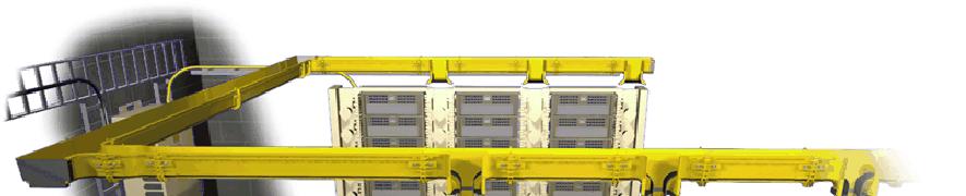
6 Cable-Temperature Stabilized SJD / TAB 6

7 Fiber Cable Wrap Watch Spring Design SJD / TAB 7

8 CB Main Distribution Frame SJD / TAB 8
9 8.5in. 14.5in. 17.0in. 36.0in.(max) SS Splice Enclosure 2" Liquid-Tight FMC 19.0in. (min) Antenna Umbilical Jumper Connector 1 5/8" Unitstrut 6" X 2" Threaded PVC 45 degree Y Track Level Unistrut set in Concrete to 18" depth SJD / TAB Existing 6" Waveguide Conduit 9

10 ITT Industries, Cannon 12 Single mode FOMC FOMC 12C Plug Assembly P/N with Break-Away style assembly SJD / TAB 10
11 EVLA North Arm Fiber Cable Plan DN2 DN3 DN4 DN5 DN6 DN7 DN8 DN9 CN5 CN6 CN7 CN8 CN9 STDN.01 STCN.01 TDN 96 f iber 2,604 f t 60 f iber 4,173 f t TCN TBN 60 f iber 12,965 f t Control Building AN9 AN8 AN7 AN6 AN5 BN9 BN8 BN7 BN6 BN5 STAN.03 STAN.02 STBN.01 Symbol Key TANc AN9 STAN.03 Splice Manhole Trunk Cable Homerun Cable TANc 36 f iber 20,709 f t SJD / TAB 11 TANb 60 f iber 13,642 f t STAN.01 TANa 60 f iber 12,965 f t

12 Cable Burial Plan Direct Burial Splice Box 12

13 Typical Termination Room SJD / TAB 13
14 Termination Floor Plan West North East System SJD / TAB 14 9'-5" 4'-0" 1'-10" 3'-7" Splice (future) Splice 4'- 10" 3'- 0" 12'-6" 20'-4"
15 Termination Panel SJD / TAB 15


16 Patch Panels Similar to Termination Panel MCB Located in Control Room LO Located in Data Rack Area IF Located in the Correlator Room SJD / TAB 16
17 MCB Network Standard Ethernet ( two Fibers ) COTS Network Router 1 Gbit/s to antennas 100 Mbit/s in the antennas and Control Room Support ~48 nodes in each antenna Two multi-mode fibers per node Fiber to each Module Patch Panel will be located in the Control room SJD / TAB 17


18 MCB Network Hardware 1 Gbit/s Transceivers Typical Equipment used to determine RFI Will be installed in shielded enclosure in the Antennas SJD / TAB 18
19 LO System Responsible for Lasers, Modulators, Fiber, Circulators, Receivers Integrated into the LO module Phase stable system LO Patch panel located in the Data Rack Area Fiber test equipment System Self-tests included SJD / TAB 19
20 LO Block Diagram MASTER OFFSET GENERATOR MASTER LO MASTER LO 128 Hz 5 MHz 128 Hz TO PHASE MONITOR DCS SYSTEM ROUND TRIP PHASE MEASUREMENT ZERO CROSSING DETECTOR PLL 512 MHz VCXO 512 MHz VCO PLL 512 MHz Hz MASTER LO GENERATOR 512 MHz CENTERAL FO SYSTEM MOD DEMOD LASER OPTICAL ANTENNA FO SYSTEM circulator SJD / TAB 20 DEMOD PLL CLEAN UP LO REFERENCE RECEIVER 512 MHz VCXO 512 MHz
21 IF Parameters Bit Rate / Channel Number WDM Channels Channel Spacing Channel Wavelengths Bit Error Rate Digital RMS SNR (Q) Maximum Fiber Length Minimum Fiber Length Operation Temperature 10 Gbits/s 12 Channels 200 GHz Spacing C-Band 10-9 Initial, 10-6 Final 6 - Initial, Final 21.6 km 625 m -12 C to 35 C SJD / TAB 21
22 IF Signal Path SJD / TAB 22
23 IF Patch Panel Located in the Correlator room Includes Fiber Amplifiers Provides signals for De-MUX hardware Manual Test Equipment Full Signal Communication Analyzer Optical Spectrum Analyzer SJD / TAB 23

24 Rack Mount EDFA MCB adjustable Gain of each amplifier Also measures in/out optical power SJD / TAB 24
25 DAQ EVLA Budget Dollars in Millions Years $ per Year Running total SJD / TAB 25
26 2002 Fiber Schedule Conduit to Manhole Feb 2002 Procure Trencher Feb 2002 RFI of MCB hardware Jun 2002 Install MCB network in AOC July 2002 Take Delivery of Fiber Cable Aug 2002 Cable spool to AOC Aug 2002 First Fiber in the ground Oct 2002 Start Termination Panel Sept 2002 SJD / TAB 26
27 2003 Fiber Schedule Bench integration MCB & IF Jan 2003 Patch Panel locations finalized Jan 2003 Accessible MCB from AOC Feb 2003 To Barn, Master Pad and test Pad (CW5) Bench Integration LO system Mar 2003 Install Fiber on test antenna April 2003 Install MCB hardware on test antenna May 2003 Install DTS & LO on test antenna June 2003 Install de-formatter and D-to-A July 2003 Decommission West-arm waveguide June 2006 SJD / TAB 27
28 Conclusion Three systems will be supported On Board Tests Incorporated ( MCB) Patch Panels will have test equipment IF Data Format supports Growth New Mexico Array and VLBA Fiber System supports Growth E Array, New Mexico Array and VLBA SJD / TAB 28
29 RF BaseBand (8) 2-4 GHz Bands Left Polarization Right Polarization UX Converter Four GHz Bands IF A IF B IF C IF D Down Converter Down Converter Down Converter Down Converter Two 3-bit One 8-bit Samplers A Two 3-bit One 8-bit Samplers B Two 3-bit One 8-bit Samplers C Two 3-bit One 8-bit Samplers D De-multiplexer 3/16 bits wide De-multiplexer 3/16 bits wide De-multiplexer 3/16 bits wide De-multiplexer 3/16 bits wide IF-A Three 128 bit Formatters L2_IF-L Three 128 bit Formatters L1_IF-R Three128 bit Formatters L2_IF-R Three 128 bit Formatters Lasers Lasers Lasers Lasers L-1 L-2 L-3 L-4 L-5 L-6 L-7 L-8 L-9 L-10 L-11 L-12 Passive Optical Coupler SJD / TAB 29 Single optical fiber
30 IF Transmitters Twelve Lasers ITU Channels GHz spacing Automated Test Output Power Measured at Each Laser Test Patterns in Formatter MCB accessible Manual Optical Power Measurements Can be measured at the MUX output SJD / TAB 30

31 Proposed Frame Format EVLA Memo #33 SJD / TAB 31
FIBER OPTICS SYTEM. EVLA Project Book, Chapter 7. Steve Durand Last Changed: 2001-November 14
 EVLA Project Book, Chapter 7 Revision History 2001-Aug 22: Initial release 2001-Nov 14: Revision one FIBER OPTICS SYTEM Steve Durand Last Changed: 2001-November 14 Summary 7.1 Introduction The EVLA makes
EVLA Memo No. 43 Operational Performance of the EVLA Digital Transmission System
 EVLA Memo No. 43 Operational Performance of the EVLA Digital Transmission System James Jackson and Steven Durand National Radio Astronomy Observatory, Socorro, New Mexico Paper presented August 2002 at
Optical Delay Line Application Note
 1 Optical Delay Line Application Note 1.1 General Optical delay lines system (ODL), incorporates a high performance lasers such as DFBs, optical modulators for high operation frequencies, photodiodes,
PR-12-B-M. 12 GHz PhotoReceiver, Module. Features. Applications. Functional Diagram
 PR-12-B-M 12 GHz PhotoReceiver, Module The Optilab PR-12-B-M is a 12 GHz bandwidth amplified PIN photodiode receiver module, designed for RF over fiber, antenna remoting, and broadband RF signals transmission
TOWER PHOTONICS STATUS UPDATE KM3 COLLABORATION MEETING LNS CATANIA- 7/12/2012. A. D Amico
 TOWER PHOTONICS STATUS UPDATE KM3 COLLABORATION MEETING LNS CATANIA- 7/12/2012 SUMMARY Optical Transport Requirements: update Multiplexing Strategy: All-optical Photonics at Tower base: Multiplexer and
Optiva RF-Over-Fiber Design Tool User s Guide. Revision 1.0 March 27, 2015
 Optiva RF-Over-Fiber Design Tool User s Guide Revision 1.0 March 27, 2015 2015 Jenco Technologies Inc. All rights reserved. Every attempt has been made to make this material complete, accurate, and up-to-date.
EVLA Memo 105. Phase coherence of the EVLA radio telescope
 EVLA Memo 105 Phase coherence of the EVLA radio telescope Steven Durand, James Jackson, and Keith Morris National Radio Astronomy Observatory, 1003 Lopezville Road, Socorro, NM, USA 87801 ABSTRACT The
Optical Phase-Locking and Wavelength Synthesis
 2014 IEEE Compound Semiconductor Integrated Circuits Symposium, October 21-23, La Jolla, CA. Optical Phase-Locking and Wavelength Synthesis M.J.W. Rodwell, H.C. Park, M. Piels, M. Lu, A. Sivananthan, E.
Long-Haul DWDM RF Fiber Optic Link System
 EMCORE Corporation - Broadband Division, Alhambra, CA, USA ABSTRACT EMCORE s vertically integrated ISO-9001 facility, staffed with our optics/rf engineering team, has been successfully designing and manufacturing
Optical Digital Transmission Systems. Xavier Fernando ADROIT Lab Ryerson University
 Optical Digital Transmission Systems Xavier Fernando ADROIT Lab Ryerson University Overview In this section we cover point-to-point digital transmission link design issues (Ch8): Link power budget calculations
Longer baselines and how it impacts the ALMA Central LO
 Longer baselines and how it impacts the ALMA Central LO 1 C. Jacques - NRAO October 3-4-5 2017 ALMA LBW Quick overview of current system Getting the data back is not the problem (digital transmission),
VLA Electronics Memo # 244. Fiber Optic Transmitter/Receiver Duplication for the Pie Town Link. Kurt Caviggia August 15, 2002
 VLA Electronics Memo # 244 Fiber Optic Transmitter/Receiver Duplication for the Pie Town Link Kurt Caviggia August 15, 2002 Caviggia Page 2 of 33 Abstract: In this National Radio Astronomy Observatory
Reference Distribution
 EPAC 08, Genoa, Italy RF Reference Signal Distribution System for FAIR M. Bousonville, GSI, Darmstadt, Germany P. Meissner, Technical University Darmstadt, Germany Dipl.-Ing. Michael Bousonville Page 1
70/140 MHz IF Fiber Optic Link
 70/140 MHz IF Fiber Optic Link Product Description Features & Benefits IF-Band: 10 200 MHz Up to 10Km distance Powerful management capabilities via a front panel LCD and rack mounted SNMP 1550nm and CWDM
AC9000 INTELLIGENT FIBRE OPTIC PLATFORM
 Kari Mäki 20.12.2012 1(7) 9000 INTLLIGNT FIBR PTIC PLATFRM Features The 9000 is an intelligent 4 output optical node of x product family. It is based on fixed platform but flexible modular solution, supporting
Headend Optics Platform (CH3000)
") arris.com Headend Optics Platform (CH3000) HT3580H Series Quad-Density Full Spectrum DWDM Transmitter System FEATURES DWDM transmitter: up to 16 wavelengths on ITU grid Hot plug-in/out, individually replaceable
arris.com Headend Optics Platform (CH3000) HT3580H Series Quad-Density Full Spectrum DWDM Transmitter System FEATURES DWDM transmitter: up to 16 wavelengths on ITU grid Hot plug-in/out, individually replaceable
Performance of the Prototype NLC RF Phase and Timing Distribution System *
 SLAC PUB 8458 June 2000 Performance of the Prototype NLC RF Phase and Timing Distribution System * Josef Frisch, David G. Brown, Eugene Cisneros Stanford Linear Accelerator Center, Stanford University,
A3422 XMTDR. Digital Return Optical Transmitter Module. Features
 A3422 XMTDR Digital Return Optical Transmitter Module The A3422 XMTDR digital return optical transmitter allows RF reverse path signals to be sent back to headend via a single fiber. The RF signal is routed
FIBER OPTIC ANTENNA LINK OFW-5800/GPS. Compatible with a Wide Range of GPS Receivers Architectures. Logistically Supported with COTS Hardware
 FIBER OPTIC ANTENNA LINK OFW-5800/GPS Compatible with a Wide Range of GPS Receivers Architectures Designed to Operate within the Naval Electromagnetic Environment Designed and Manufactured to Meet Naval
Data Center & Cloud Computing DATASHEET. Dual & Single Fiber DWDM OADM. Data Center & Cloud Computing. Infrastruture Solutions
 Data Center & Cloud Computing DATASHEET Dual & Single Fiber DWDM OADM Data Center & Cloud Computing Infrastruture Solutions REV.1.0 2018 DWDM OADM 01 1 Introduction FS.COM designs and offers all types
DATASHEET. Data Center & Cloud Computing Infrastruture Solutions
 Data Center & Cloud Computing DATASHEET 8 Channels 1470-1610nm Dual Fiber CWDM Mux Demux W/Expansion Port, FMU Plug-in Module, LC/UPC Data Center & Cloud Computing Infrastruture Solutions REV.1.0 2017
FIBER OPTIC COMMUNICATION LINK LOSS, OSNR AND FEC PERFORMANCE
 Tallinn University of Technology Laboratory exercise 2 of Fiber Optical Communication course FIBER OPTIC COMMUNICATION LINK LOSS, OSNR AND FEC PERFORMANCE Tallinn 2016 Please note that the OSA (Optical
ADVANCED EXPERIMENTS IN MODERN COMMUNICATIONS
 ADVANCED EXPERIMENTS IN MODERN COMMUNICATIONS NEW FIBER OPTICS KIT New Generation Single-Board Telecoms Experimenter for Advanced Experiments Emona ETT-101 BiSKIT Multi-Experiment Telecommunications &
AC9000 INTELLIGENT FIBRE OPTIC PLATFORM
 Kari Mäki 4.4.2012 1(7) 9000 INTLLIGNT FIBR PTIC PLATFRM Features The 9000 is an intelligent 4 output optical node of x product family. It is based on fixed platform but flexible modular solution, supporting
Testing of DWDM + CWDM high speed systems. Christian Till Technical Sales Engineer, EXFO
 Testing of DWDM + CWDM high speed systems Christian Till Technical Sales Engineer, EXFO Need more bandwidth? xwdm - Class of WDM Devices Wavelength Division Multiplexing (WDM) : Access 2 channels 1310nm,
Figure 1 Photo of an Upgraded Low Band Receiver
 NATIONAL RADIO ASTRONOMY OBSERVATORY SOCORRO, NEW MEXICO EVLA TECHNICAL REPORT #175 LOW BAND RECEIVER PERFORMANCE SEPTMBER 27, 2013 S.DURAND, P.HARDEN Upgraded low band receivers, figure 1, were installed
White Rabbit in Time & Frequency Metrology
 VTT TECHNICAL RESEARCH CENTRE OF FINLAND LTD White Rabbit in Time & Frequency Metrology Anders Wallin White Rabbit Workshop 2016-03-15, Amsterdam Long(est?) WR link Fiber asymmetry and calibration Stability
Data Center & Cloud Computing DATASHEET. Dual & Single Fiber DWDM OADM. Data Center & Cloud Computing. Infrastruture Solutions
 Data Center & Cloud Computing DATASHEET Dual & Single Fiber DWDM OADM Data Center & Cloud Computing Infrastruture Solutions REV.1.0 2018 DWDM OADM 01 1 Introduction FS.COM designs and offers all types
WWDM Transceiver Module for 10-Gb/s Ethernet
 WWDM Transceiver Module for 10-Gb/s Ethernet Brian E. Lemoff Hewlett-Packard Laboratories lemoff@hpl.hp.com IEEE 802.3 HSSG Interim Meeting Coeur d Alene, Idaho June 1-3, 1999 Why pursue WWDM for the LAN?
Data Digitization & Transmission Session Moderator: Chris Langley
 Data Digitization & Transmission Session Moderator: Chris Langley Atacama Large Millimeter/submillimeter Array Karl G. Jansky Very Large Array Robert C. Byrd Green Bank Telescope Very Long Baseline Array
Optical Transport Technologies and Trends
 Optical Transport Technologies and Trends A Network Planning Perspective Sept 1, 2014 Dion Leung, Director of Solutions and Sales Engineering dleung@btisystem.com About BTI Customers 380+ worldwide in
Holography Transmitter Design Bill Shillue 2000-Oct-03
 Holography Transmitter Design Bill Shillue 2000-Oct-03 Planned Photonic Reference Distribution for Test Interferometer The transmitter for the holography receiver is made up mostly of parts that are already
11.1 Gbit/s Pluggable Small Form Factor DWDM Optical Transceiver Module
 INFORMATION & COMMUNICATIONS 11.1 Gbit/s Pluggable Small Form Factor DWDM Transceiver Module Yoji SHIMADA*, Shingo INOUE, Shimako ANZAI, Hiroshi KAWAMURA, Shogo AMARI and Kenji OTOBE We have developed
Compact Model Fiber Deep Node 862 MHz with 42/54 MHz Split
 Optoelectronics Compact Model 90090 Fiber Deep Node 862 MHz with 42/54 MHz Split Description The Scientific-Atlanta Compact Model 90090 Fiber Deep Node is a small, low-cost, 110V AC powered node that addresses
CWDM Cisco CWDM wavelengths (nm)
") Cisco Enhanced Wavelength Division Multiplexing Product Line The Cisco enhanced wavelength-division multiplexing (EWDM) product line allows users to scale the speed and capacity of the services offered
Cisco Enhanced Wavelength Division Multiplexing Product Line The Cisco enhanced wavelength-division multiplexing (EWDM) product line allows users to scale the speed and capacity of the services offered
GBT. LO Reference Distribution System. Maintenance Manual. M. J. Stennes September 15, 2004
 GBT LO Reference Distribution System Maintenance Manual M. J. Stennes September 15, 2004 Table of Contents i. Abstract.. 2 I. System Description.. 3 II Maintenance Procedures.. 7 (a) Cable length adjustments
RF over Fiber Optic Transceiver OZ816 Series Ultra Broadband 6 GHz
 FEATURES 30 MHz to 6.0 GHz Bandwidth Approx Size: 3 x 5 x 1.25 in. Weight ¾ pound 40 C to +5 C Operating Temperature LD/PD Monitoring & Alarm High Spurious Free Dynamic Range Automatic Optical Power Control
EMC Evaluation at Green Bank: Emissions and Shield Effectiveness
 EMC Evaluation at Green Bank: Emissions and Shield Effectiveness National Radio Astronomy Observatory Carla Beaudet Green Bank RFI Group Leader Emissions Evaluation: Standards ITU-R RA.769 specifies (typical)
Measuring Photonic, Optoelectronic and Electro optic S parameters using an advanced photonic module
 Measuring Photonic, Optoelectronic and Electro optic S parameters using an advanced photonic module APPLICATION NOTE This application note describes the procedure for electro-optic measurements of both
MODEL BLN GHz FIBER DEEP NODE STARLINE SERIES
 MODEL BLN100 1 1 GHz FIBER DEEP NODE STARLINE SERIES The BLN100 optical node is an essential building block in evolving Hybrid Fiber Coaxial (HFC) network architectures enabling amplifier to node conversions.
Extending the Offset Frequency Range of the D2-135 Offset Phase Lock Servo by Indirect Locking
 Extending the Offset Frequency Range of the D2-135 Offset Phase Lock Servo by Indirect Locking Introduction The Vescent Photonics D2-135 Offset Phase Lock Servo is normally used to phase lock a pair of
Integrated 90deg Hybrid Balanced Receiver
 1. INTRODUCTION Integrated 90deg Hybrid Balanced Receiver This document describes one of 's innovated products, a 90deg optical hybrid integrated with balanced photo-receivers, which can be used in optical
SILICA OPTICAL WAVEGUIDE DEVICES
 SILICA OPTICAL WAVEGUIDE DEVICES Splitter Module A single mode 1xn splitter has one input and multiple outputs (n) for dividing an optical signals SPECIFICATION Model No. 1x n Insertion loss Typical Maximum
DRC 3500 Versatile Ka-Band Transceiver
 DRC 3500 Key Features: Flexible Polarisation: RHCP/ LHCP and cross/co-polar 2 GHz operation by switchable sub-bands Optimised, integrated Feed-chain for highest EIRP and G/T True 5 Watt P1dB at the Feed
2009 CubeSat Developer s Workshop San Luis Obispo, CA
 Exploiting Link Dynamics in LEO-to-Ground Communications 2009 CubeSat Developer s Workshop San Luis Obispo, CA Michael Caffrey mpc@lanl.gov Joseph Palmer jmp@lanl.gov Los Alamos National Laboratory Paper
Digital Return System
 SG4 DRT 2X 85 and MBN DRT 2X 85 Transmitters GX2 DRR 2X 85 and CHP D2RRX 85 Receivers FEATURES Allows return bandwidth expansion up to 85 MHz Easy node segmentation with 2X RF TDM Simplified logistics
CXE880 FIBRE OPTIC NODE
 Kari Mäki 8.1.2008 1(5) CXE880 FIBRE OPTIC NODE The CXE880 is a fibre deep optical node. It is designed for cases where high performance and cost effectiveness are a demand. Requirements of future networks,
INSTALLATION and OPERATION INSTRUCTIONS. FOR FiberLink BI-DIRECTIONAL AMPLIFIER WITH DIVERSITY MW-FBDA-800AB-50W-DIV
 INSTALLATION and OPERATION INSTRUCTIONS FOR FiberLink BI-DIRECTIONAL AMPLIFIER WITH DIVERSITY MW-FBDA-800AB-50W-DIV Page 1 of 15 TABLE OF CONTENTS PARA No. PARAGRAPH PAGE No. 1. OVERVIEW 3 2. COMPONENT
Cisco EDR 85 System: Modules for Cisco GainMaker and GS7000
 Data Sheet Cisco EDR 85 System: Modules for Cisco GainMaker and GS7000 The Cisco Enhanced Digital Return (EDR) 85 System expands the functionality of Cisco GS7000 and Cisco GainMaker Nodes by increasing
Gigabit Transmission in 60-GHz-Band Using Optical Frequency Up-Conversion by Semiconductor Optical Amplifier and Photodiode Configuration
 22 Gigabit Transmission in 60-GHz-Band Using Optical Frequency Up-Conversion by Semiconductor Optical Amplifier and Photodiode Configuration Jun-Hyuk Seo, and Woo-Young Choi Department of Electrical and
Elements of Optical Networking
 Bruckner Elements of Optical Networking Basics and practice of optical data communication With 217 Figures, 13 Tables and 93 Exercises Translated by Patricia Joliet VIEWEG+ TEUBNER VII Content Preface
Model 6944 and 6940 Node bdr Digital Reverse 4:1 Multiplexing System designed for Prisma II Platform
 Optoelectronics Model 6944 and 6940 Node bdr Digital Reverse 4:1 Multiplexing System designed for Prisma II Platform Description The bdr Digital Reverse 4:1 Multiplexing System expands the functionality
Optical phase-locked loop for coherent transmission over 500 km using heterodyne detection with fiber lasers
 Optical phase-locked loop for coherent transmission over 500 km using heterodyne detection with fiber lasers Keisuke Kasai a), Jumpei Hongo, Masato Yoshida, and Masataka Nakazawa Research Institute of
Cisco Enhanced Digital Return (EDR) 85 System Compact Segmentable Nodes
 85 System Compact Segmentable Nodes") Cisco Enhanced Digital Return (EDR) 85 System Compact Segmentable Nodes The Cisco Enhanced Digital Return (EDR) 85 System expands the functionality of Compact Segmentable Nodes by increasing the performance,
Cisco Enhanced Digital Return (EDR) 85 System Compact Segmentable Nodes The Cisco Enhanced Digital Return (EDR) 85 System expands the functionality of Compact Segmentable Nodes by increasing the performance,
Passive Optical Components for Optical Fiber Transmission
 Passive Optical Components for Optical Fiber Transmission Norio Kashima Artech House Boston London Contents Preface Part I Basic Technologies 1 Chapter 1 Introduction to Passive Optical Components 3 1.1
Filling the fiber: Factors involved in absolute fiber capacity Geoff Bennett, Infinera UKNOF September 2007
 Filling the fiber: Factors involved in absolute fiber capacity Geoff Bennett, Infinera UKNOF September 2007 Initial assumption We are aiming to achieve the highest possible capacity from an individual
Fiber-based components. by: Khanh Kieu
 Fiber-based components by: Khanh Kieu Projects 1. Handling optical fibers, numerical aperture 2. Measurement of fiber attenuation 3. Connectors and splices 4. Free space coupling of laser into fibers 5.
GS7000 and GainMaker Reverse Segmentable Node bdr Digital Reverse 2:1 Multiplexing System
 GS7000 and GainMaker Reverse Segmentable Node bdr Digital Reverse 2:1 Multiplexing System The bdr Digital Reverse 2:1 Multiplexing System expands the functionality of the GS7000 and GainMaker Reverse Segmentable
Sentinel 3: Speed, flexibility, certainty
 ]= V1.2 Sentinel 3: Speed, flexibility, certainty Sentinel 3 is the most advanced RF over fiber test and measurement system for: EMP test and EMC conformance HIRF aircraft clearance Simulated lightning
2009 Small Satellite Conference Logan, Utah
 Exploiting Link Dynamics in LEO-to-Ground Communications 2009 Small Satellite Conference Logan, Utah Joseph Palmer jmp@lanl.gov Michael Caffrey mpc@lanl.gov Los Alamos National Laboratory Paper Abstract
Pluggable Transceiver Modules
 APPENDIXB Revised: April 2012 This appendix provides descriptions and specifications for the pluggable transceiver modules that are supported on the Catalyst 6 series Ethernet switching modules. The appendix
SHF Communication Technologies AG
 SHF Communication Technologies AG Wilhelm-von-Siemens-Str. 23 Aufgang D 12277 Berlin Marienfelde Germany Phone ++49 30 / 772 05 10 Fax ++49 30 / 753 10 78 E-Mail: sales@shf.biz Web: http://www.shf.biz
NTT DOCOMO Technical Journal. RoF System for Dual W-CDMA and LTE Systems. 1. Introduction
 RoF System for Dual W-CDMA and LTE Systems LTE RoF 2 2 MIMO RoF System for Dual W-CDMA and LTE Systems NTT DOCOMO began a high-speed, high-capacity, lowlatency service using the LTE system in December
Pass Cisco Exam
 Pass Cisco 642-321 Exam Number: 642-321 Passing Score: 800 Time Limit: 120 min File Version: 38.8 http://www.gratisexam.com/ Pass Cisco 642-321 Exam Exam Name : Cisco Optical SDH Exam (SDH) Braindumps
Integrated receivers for mid-band SKA. Suzy Jackson Engineer, Australia Telescope National Facility
 Integrated receivers for mid-band SKA Suzy Jackson Engineer, Australia Telescope National Facility SKADS FP6 Meeting Chateau de Limelette 4-6 November, 2009 Talk overview Mid band SKA receiver challenges
The DARPA 100Gb/s RF Backbone Program
 The DARPA 100Gb/s RF Backbone Program Dr. Ted Woodward Program Manager, DARPA/STO Briefing Prepared for NSF mmw RCN workshop Madison, WI 19 July 2017 1 100 Gb/s RF Backbone (100G) Objective: Capacity AND
Lecture 1: Introduction
 Optical Fibre Communication Systems Lecture 1: Introduction Professor Z Ghassemlooy Electronics & It Division School of Engineering Sheffield Hallam University U.K. www.shu.ac.uk/ocr 1 Contents Reading
FMU-MC09-A/B, Pair Packaged DATASHEET. Data Center & Cloud Computing Infrastruture Solutions
 Data Center & Cloud Computing DATASHEET FMU-MC09-A/B, Pair Packaged 9 Channels Single Fiber CWDM Mux Demux, Plug-in Module, LC/UPC Data Center & Cloud Computing Infrastruture Solutions REV.1.0 2018 Overview
Integrated receivers for mid-band SKA. Suzy Jackson Engineer, Australia Telescope National Facility
 Integrated receivers for mid-band SKA Suzy Jackson Engineer, Australia Telescope National Facility ASKAP/SKA Special Technical Brief 23 rd October, 2009 Talk overview Mid band SKA receiver challenges ASKAP
100G CWDM4 MSA Technical Specifications 2km Optical Specifications
 100G CWDM4 MSA Technical Specifications 2km Specifications Participants Editor David Lewis, LUMENTUM Comment Resolution Administrator Chris Cole, Finisar The following companies were members of the CWDM4
GainStar 1 GHz Node with 42/54 MHz Split
 GainStar 1 GHz Node with 42/54 MHz Split The 1 GHz GainStar Node (GSN) is specifically designed to serve in HFC networks. With its modular design of Optics and RF amplifier electronics, the GSN can provide
Digital Return System
 arris.com Digital Return System SG4 DRT 2X 85 and MBN DRT 2X 85 Transmitters GX2 DRR 2X 85 and CHP D2RRX 85 Receivers FEATURES Allows return bandwidth expansion up to 85 MHz Easy node segmentation with
Figure 1: Worst-Case Emissions *FCC Class B compliance not estimated 4 below 200 MHz due to lack of antenna calibration and chamber reflectivity
 On Monday, May 02, 2016, Carla Beaudet performed RFI tests on the Prime Focus Phased Array Feed backend, housed in a RFI chassis built by NRAO, the assembly henceforth referred to as the EUT, (Equipment
GS7000 & GainMaker Reverse Segmentable Node bdr Digital Reverse 2:1 Multiplexing System
 Optoelectronics GS7000 & GainMaker Reverse Segmentable Node bdr Digital Reverse 2:1 Multiplexing System Description The bdr Digital Reverse 2:1 Multiplexing System expands the functionality of the Scientific-Atlanta
CXE880 FIBRE OPTIC NODE
 Kari Mäki 4.3.2008 1(6) CXE880 FIBRE OPTIC NODE The CXE880 is a fibre deep optical node. It is designed for cases where high performance and cost effectiveness are a demand. Requirements of future networks,
Cisco Prisma II Quad Optical Input Enhanced Digital Return (EDR) Receiver for Compact Segmentable Nodes
 Receiver for Compact Segmentable Nodes") Data Sheet Cisco Prisma II Quad Optical Input Enhanced Digital Return (EDR) Receiver for Compact Segmentable Nodes The Cisco Quad Optical Input Enhanced Digital Return (Q-EDR) 85 Receiver expands the Cisco
Data Sheet Cisco Prisma II Quad Optical Input Enhanced Digital Return (EDR) Receiver for Compact Segmentable Nodes The Cisco Quad Optical Input Enhanced Digital Return (Q-EDR) 85 Receiver expands the Cisco
ModBox-OBand-56GBaud-PAM4 O-Band, 56 Gbaud PAM-4 Reference Transmitter
 -OBand-5GBaud-PAM4 O-Band, 5 Gbaud PAM-4 Reference Transmitter The -OBand-5Gbaud-PAM4 is a 4-level Pulse Amplitude Modulation (PAM-4) Optical Reference Transmitter that generates in the O-band excellent
High-Fidelity RF over Fiber Links
 High-Fidelity RF over Fiber Links 8 Uplander Way, Suite 2 Culver City, CA 923 Rugged, Small Form Factor Transmitter and Receiver Modules for RF over Optical Fiber Links Applications Fiber to the Antenna:
DATASHEET. Data Center & Cloud Computing Infrastruture Solutions. 4 Channels nm Dual Fiber CWDM Mux Demux FMU Plug-in Module, LC/UPC
 Data Center & Cloud Computing DATASHEET 4 Channels 1270-1330nm Dual Fiber CWDM Mux Demux FMU Plug-in Module, LC/UPC Data Center & Cloud Computing Infrastruture Solutions REV.1.0 2018 01 Overview The CWDM
AMPLIFIER RESEARCH... APPLICATION NOTE: 23
 AMPLIFIER RESEARCH... APPLICATION NOTE: 23 PRODUCTS THAT PROVIDE 200 V/m CW OR PM AT A DISTANCE OF 1 METER 1 The Amplifier / Antenna / Cell combinations shown in Table 1 provide various means of generating
INTRODUCTION TO COMMUNICATION SYSTEMS AND TRANSMISSION MEDIA
 COMM.ENG INTRODUCTION TO COMMUNICATION SYSTEMS AND TRANSMISSION MEDIA 9/9/2017 LECTURES 1 Objectives To give a background on Communication system components and channels (media) A distinction between analogue
Extending 100Gbit/s Ethernet. Ariën Vijn
 Extending 100Gbit/s Ethernet Ariën Vijn arien.vijn@ams-ix.net Agenda AMS-IX 100Gbit/s technology Problem statement Optical Amplifier development Metro DWDM equipment AMS-IX AMS-IX 100Gbit/s technology
DATASHEET. Data Center & Cloud Computing Infrastruture Solutions
 Data Center & Cloud Computing DATASHEET 18 Channels Dual Fiber CWDM Mux Demux + Monitor Port 1270-1610nm, 1U Rack Mount, LC/UPC Data Center & Cloud Computing Infrastruture Solutions REV.1.0 2017 01 Overview
VePAL UX400 Universal Test Platform
 CWDM and DWDM Testing VePAL UX400 Universal Test Platform Optical Spectrum/Channel Analyzer for CWDM and DWDM Networks Using superior micro-optic design and MEMS tuning technology, the UX400 OSA module
Optical Fibers p. 1 Basic Concepts p. 1 Step-Index Fibers p. 2 Graded-Index Fibers p. 4 Design and Fabrication p. 6 Silica Fibers p.
 Preface p. xiii Optical Fibers p. 1 Basic Concepts p. 1 Step-Index Fibers p. 2 Graded-Index Fibers p. 4 Design and Fabrication p. 6 Silica Fibers p. 6 Plastic Optical Fibers p. 9 Microstructure Optical
How Bend Insensitive Multimode Fiber is Affecting Installation and Testing of Enterprise and Data Center Cabling
 How Bend Insensitive Multimode Fiber is Affecting Installation and Testing of Enterprise and Data Center Cabling David Mazzarese, Technical Manager, Fiber Systems and Standards Engineering, OFS Learning
DATASHEET FMU-MC04E-A/B, Pair Packaged, w/expansion Port
 Data Center & Cloud Computing DATASHEET FMU-MC04E-A/B, Pair Packaged, w/expansion Port 4 Channels Single Fiber CWDM Mux Demux, Plug-in Module, LC/UPC Data Center & Cloud Computing Infrastruture Solutions
Analysis of four channel CWDM Transceiver Modules based on Extinction Ratio and with the use of EDFA
 Analysis of four channel CWDM Transceiver Modules based on Extinction Ratio and with the use of EDFA P.P. Hema [1], Prof. A.Sangeetha [2] School of Electronics Engineering [SENSE], VIT University, Vellore
Femtosecond Synchronization of Laser Systems for the LCLS
 Femtosecond Synchronization of Laser Systems for the LCLS, Lawrence Doolittle, Gang Huang, John W. Staples, Russell Wilcox (LBNL) John Arthur, Josef Frisch, William White (SLAC) 26 Aug 2010 FEL2010 1 Berkeley
ALMA Interferometer and Band 7 Cartridge
 ALMA Interferometer and Band 7 Cartridge B7 Cartridge designed, assembled and tested by: S. Mahieu, D. Maier (mixer team lead), B. Lazareff (now at IPAG) G. Celestin, J. Chalain, D. Geoffroy, F. Laslaz,
Optiva OTS-2 18 GHz Amplified Microwave Band Fiber Optic Links
 MHz to 18 GHz Amplified Microwave Transport System The Optiva OTS-2 18 GHz Microwave Band transmitter and receiver are ideal to construct transparent fiber optic links in the MHz to 18 GHz frequency range
EVLA Memo 108 LO/IF Phase Dependence on Antenna Elevation
 EVLA Memo 108 LO/IF Phase Dependence on Antenna Elevation Abstract K. Morris, J. Jackson, V. Dhawan June 18, 2007 EVLA test observations revealed interferometric phase changes that track EVLA antenna elevation
SYLLABUS Optical Fiber Communication
 SYLLABUS Optical Fiber Communication Subject Code : IA Marks : 25 No. of Lecture Hrs/Week : 04 Exam Hours : 03 Total no. of Lecture Hrs. : 52 Exam Marks : 100 UNIT - 1 PART - A OVERVIEW OF OPTICAL FIBER
ODN4P. Optical Distribution Node, Four Ports. About the Product
 About the Product The Light Link Series 2, deep-fibre Optical Distribution Node ODN4P is a prime building block for highperformance networks, designed for adaptability, scalability and optional return-path
AC8800 INTELLIGENT FIBRE OPTIC PLATFORM
 Kari Mäki 27.5.2010 1(7) AC8800 INTLLIGNT FIBR PTIC PLATFRM The AC8800 is a dual active output node. It is based on fixed platform but flexible modular solution. It supports two optical receivers with
AC500 AMPLIFIER PLATFORM
 Broadband Cable Networks / Kari Mäki March 18, 2004 1(6) AC500 AMPLIFIER PLATFORM The AC500 is a single active output amplifier with 39 of gain. The amplifier can be used as in distribution purposes in
Emerging Subsea Networks
 EVALUATION OF NONLINEAR IMPAIRMENT FROM NARROW- BAND UNPOLARIZED IDLERS IN COHERENT TRANSMISSION ON DISPERSION-MANAGED SUBMARINE CABLE SYSTEMS Masashi Binkai, Keisuke Matsuda, Tsuyoshi Yoshida, Naoki Suzuki,
Project: IEEE P Working Group for Wireless Personal Area Networks N
 July, 2008 Project: IEEE P802.15 Working Group for Wireless Personal Area Networks N (WPANs( WPANs) Submission Title: Millimeter-wave Photonics for High Data Rate Wireless Communication Systems Date Submitted:
ModBox-CBand-NRZ series C-Band, 28 Gb/s, 44 Gb/s, 50 Gb/s Reference Transmitters
 The is a family of Reference Transmitters that generate excellent quality NRZ optical data streams up to 28 Gb/s, 44 Gb/s, 50 Gb/s in the C-band. These transmitters produce very clean eye diagrams with
Specification for Radiated susceptibility Test
 1 of 11 General Information on Radiated susceptibility test Supported frequency Range : 20MHz to 6GHz Supported Field strength : 30V/m at 3 meter distance 100V/m at 1 meter distance 2 of 11 Signal generator