REMOTE SENSOR SERIES. Description
|
|
|
- Damian Hardy
- 5 years ago
- Views:
Transcription
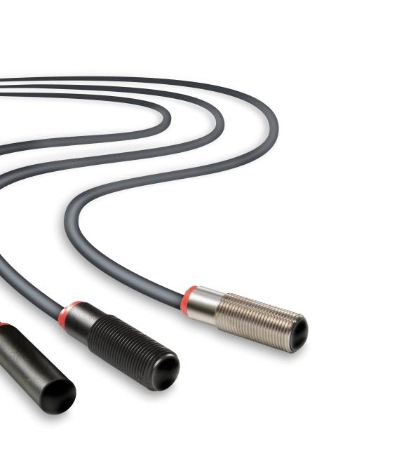
1 REMOTE SENSOR SERIES Telco s remote sensor series can always be depended on to do the job. Although simple in design and modest in size, nothing performs more reliably in hostile environments and challenging conditions then these sensors. They may be commonly under-estimated, but it does not take long to realise that they are the most powerful and versatile infrared sensors in the industry.
2

3 REMOTE SENSOR SERIES Description Operation mode and max sensing range: Thru beam: Dependent on amplifier Diffuse proximity: Dependent on amplifier Optional sensor monitor LED Wide variety of housings High tolerance to hostile environments Cable or plug connections Available with optional Atex approval The remote sensor series, which consists of a transmitter LT and receiver LR, is made to operate in conjunction with a Telco photoelectric amplifier from the PA, MPA or PAB programmes. The series is available with optional power-(lr) and output-(lt) monitor LEDs for use with any Telco photoelectric amplifier which has the sensor LED drive feature incorporated. The remote sensors are available in a wide range of housings, with either cable or plug connection, and may be used in thru beam or diffuse proximity mode. Technical Data LT LR Transmitter Diode Ga Al As, (880 nm) Photo Silicon NPN Cable Ø 4mm PVC Sleeves 2 x 0,25 mm 2 1 x 0,25 mm 2 + shield Min. cable bending radius 45 mm Environmental Data Vibration Hz, 0,5 mm Shock 30 g Light 20 incidence 101 Series > lux 100 Series > lux 110/120 Series > lux Temperature, operation 25 to +65 C Temperature, storage 40 to +80 C Sealing Class IP 67 Approvals a REMOTE PHOTOELECTRIC SYSTEMS I 13
4 REMOTE SENSOR SERIES Available Types Series Optical Connection 5 m Cable 15 m Cable 3 pin, M8 Plug 4 pin, M12 Plug Angle Housing Material Housing Type Order Reference Receiver Transmitter 101 +/ 10 +/ 6 Polycarbonate Ø10 LT 101 AP25 5 LT 101 AP25 15 LT 101 AP25 T3 LT 101 TP25 5 LT 101 TP25 15 LT 101 TP25 T3 Nickel Plated Brass M12 x 1 LT 101 TB25 5 LT 101 TB25 15 LT 101 TB25 T3 Stainless Steel LT 101 TS25 5 LT 101 TS25 15 LT 101 TS25 T3 Polyester 9,5 x 11,5 LT 101 SG 5* LT 101 SG 15* LT 101 SG T3 ABS Ø12,7 (Snap Housing) LT 101 S22 5* LT 101 S22 15* Polycarbonate Ø10 LR 101 AP25 5 LR 101 AP25 15 LR 101 AP25 T3 LR 101 TP25 5 LR 101 TP25 15 LR 101 TP25 T3 Nickel Plated Brass M12 x 1 LR 101 TB25 5 LR 101 TB25 15 LR 101 TB25 T3 Stainless Steel LR 101 TS25 5 LR 101 TS25 15 LR 101 TS25 T3 Polyester 9,5 x 11,5 LR 101 SG 5* LR 101 SG 15* LR 101 SG T3 Ø12,7 ABS LR 101 S22 5* LR 101 S22 15* (Snap Housing) Receiver Transmitter +/ / 6 +/ 7 Polycarbonate Ø10 LT 100H AP38 5 LT 100H AP38 15 LT 100H AP38 T3 LT 100H TP38 5 LT 100H TP38 15 LT 100H TP38 T3 Nickel Plated Brass M12 x 1 LT 100H TB38 5 LT 100H TB38 15 LT 100H TB38 T3 LT 100H TB58 J Stainless Steel LT 100H TS38 5 LT 100H TS38 15 LT 100H TS38 T3 LT 100H TS58 J Polycarbonate Ø10 LT 100 AP38 5 LT 100 AP38 15 LT 100 AP38 T3 LT 100 TP38 5 LT 100 TP38 15 LT 100 TP38 T3 Nickel Plated Brass M12 x 1 LT 100 TB38 5 LT 100 TB38 15 LT 100 TB38 T3 LT 100 TB58 J Stainless Steel LT 100 TS38 5 LT 100 TS38 15 LT 100 TS38 T3 LT 100 TS58 J Polycarbonate Ø10 LR 100 AP38 5 LR 100 AP38 15 LR 100 AP38 T3 LR 100 TP38 5 LR 100 TP38 15 LR 100 TP38 T3 Nickel Plated Brass M12 x 1 LR 100 TB38 5 LR 100 TB38 15 LR 100 TB38 T3 LR 100 TB58 J Stainless Steel LR 100 TS38 5 LR 100 TS38 15 LR 100 TS38 T3 LR 100 TS58 J Receiver Transmitter 110 +/ 5 +/ 3 Polycarbonate Ø10 LT 110 AP38 5 LT 110 AP38 15 LT 110 AP38 T3 LT 110 TP38 5 LT 110 TP38 15 LT 110 TP38 T3 Nickel Plated Brass M12 x 1 LT 110 TB38 5 LT 110 TB38 15 LT 110 TB38 T3 LT 110 TB58 J Stainless Steel LT 110 TS38 5 LT 110 TS38 15 LT 110 TS38 T3 LT 110 TS58 J Polycarbonate Ø10 LR 110 AP38 5 LR 110 AP38 15 LR 110 AP38 T3 LR 110 TP38 5 LR 110 TP38 15 LR 110 TP38 T3 Nickel Plated Brass M12 x 1 LR 110 TB38 5 LR 110 TB38 15 LR 110 TB38 T3 LR 110 TB58 J Stainless Steel LR 110 TS38 5 LR 110 TS38 15 LR 110 TS38 T3 LR 110 TS58 J Receiver Transmitter +/ 4 LT 120 TB45 5 LT 120 TB Nickel Plated Brass M18 x 1 +/ 2,5 LR 120 TB45 5 LR 120 TB45 15 Note: 1. Photo amplifiers to be ordered separately. 2. Remote sensors are available with optional power (LR) and output (LT) monitor LEDs for use with the applicable Telco photoelectric amplifier, which has the sensor LED drive. Add L after the series number for sensor monitor LED e.g. LT/LR 101L AP Sensors marked * are not available with this optional feature. 3. Remote sensors with cable connection are available to comply with ATEX directive marked Group II, Category 3 for gas and dust, temperature class T6, EEx na II U non-sparking component. Add /EX after the series number, e.g. LT/LR 100/EX TS I REMOTE PHOTOELECTRIC SYSTEMS
5 REMOTE SENSOR SERIES Applicable Photoelectric Amplifiers and Maximum Ranges Series Diffuse Diffuse Diffuse Diffuse Thru-beam Thru-beam Thru-beam Thru-beam Proximity Proximity Proximity Proximity Photoelectric Amplifier Series PA 01 8 m 0,6 m 10 m 0,7 m 23 m 1,6 m 45 m 3,5 m PA 09 5 m 0,4 m PA 10 A 11 m 0,9 m B 15 m 1,1 m 35 m 2 m 60 m 4 m PA m 1,1 m 40 m 2 m 70 m 5 m Multiplexed Amplifier Series MPA m 0,7 m 25 m 1,6 m 45 m 3,5 m MPA 41 A/B 8 m 0,6 m 18 m 1,3 m 35 m 2 m C/D 4 m 0,4 m 9 m 0,7 m 18 m 1,3 m MPA 81 A/B 8 m 0,6 m 18 m 1,3 m 35 m 2 m C/D 4 m 0,4 m 9 m 0,7 m 18 m 1,3 m Photoelectric Amplifier Bus Series PAB m 1,1 m 40 m 2 m 70 m 4 m PAB m 0,8 m 27 m 1,7 m 47 m 2,6 m PAB m 0,8 m 27 m 1,7 m 47 m 2,6 m Note: Sensing ranges using fibre optics, please refer to page 131. Connections Cable M8 Plug/Cable M12 Plug/Cable Transmitter Signal Red Pin 1/Brown Pin 1/Brown Transmitter Ground Pin 3/Blue Pin 3/Blue Receiver Signal Yellow Pin 4/ Pin 4/ Receiver Ground Shield Pin 3/Blue Pin 3/Blue 3 pin, M8 4 pin, M12 Sensor Plug (Male) Cable Plug (Female) Sensor Plug (Male) Cable Plug (Female) Brown Brown White Blue Blue REMOTE PHOTOELECTRIC SYSTEMS I 15
6 REMOTE SENSOR SERIES Dimensions and Descriptions Series ,5 LED 28, LED Ø 10 M12 x ,7 8,7 AP25 5/15 TP/TB/TS25 5/ Ø 9 Ø 3, Ø 9 Ø 3,5 Ø 10 M8 x 1 25 LED AP25 T3 22 M12 x 1 M8 x 1 17 LED TP/TB/TS25 T3 15 LED 15 M8 x ,5 SG 5/15 SG T3 17,5 S22 5/15 (Units in mm) Series 100/110 41,5 LED 41, LED Ø 10 M12 x 1 M12 x 1 M12 x LED AP38 5/15 TP/TB/TS38 5/15 TB/TS58 J Ø 10 M8 x 1 M12 x 1 M8 x 1 38 LED 17 LED AP38 T3 TP/TB/TS38 T3 (Units in mm) Series LED M18 x 1 24 TB45 5/15 (Units in mm) 16 I REMOTE PHOTOELECTRIC SYSTEMS
7 REMOTE SENSOR SERIES Sensing Characteristics Parallel Displacement (Thru Beam) Displacement (% of max range) Displacement (% of max range) LT 100H LT Range (normalized) Range (normalized) Series 101 X Y Series 100 X Y Displacement (% of max range) Displacement (% of max range) Range (normalized) Range (normalized) Series 110 X Y Series 120 X Y REMOTE PHOTOELECTRIC SYSTEMS I 17
8 REMOTE SENSOR SERIES Sensing Characteristics Angular Displacement (Thru Beam) Output Power (normalized) Degrees LT 101 Sensitivity (normalized) Degrees LR 101 Output Power (normalized) LT 100H LT Degrees LT 100 Sensitivity (normalized) Degrees LR 100 Output Power (normalized) Degrees LT 110 Sensitivity (normalized) Degrees LR 110 Output Power (normalized) Degrees LT 120 Sensitivity (normalized) Degrees LR 120 Telco reserves the right to change specifications without notice. 18 I REMOTE PHOTOELECTRIC SYSTEMS
9 PHOTOELECTRIC AMPLIFIER SERIES Telco s photoelectric amplifier series performs as good today as it did when it first appeared almost 25 years ago. But while the simple design of this iconic product has remained the same in all that time, the technology on the inside has been constantly refined so it continues to offer nothing less than the most reliable and powerful performance possible.
10
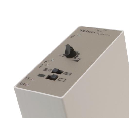
 Switch selectable light or dark function Switch selectable long or short")
11 PHOTOELECTRIC AMPLIFIER SERIES PA 01 Description Operation mode and max sensing range: Thru beam: 0-45 m Diffuse proximity: 0-3,5 m 230 V ac, 115 V ac or 24 V ac/dc supply voltage Automatic and/or manual sensitivity adjustment Sensor LED-drive Adjustable on/off time delay 1 relay or 1 transistor output STF (Patented) Switch selectable light or dark function Switch selectable long or short range Power, output and signal status indicators Test input 11-pole DIN socket connection The PA 01 is a 1-channel photoelectric amplifier, which is to be used in conjunction with a set of remote transmitter LT and receiver LR from the series 101, 100, 110 or 120. This amplifier series offers a choice between automatic and/or manual sensitivity adjustment with or without a 0-10 sec on/off time delay via integral potentiometers located on the front panel of the amplifier. Output can be selected from either a relay or an NPN/PNP transistor output. Light or dark function and long or short range are switch selectable. In automatic mode, set up is required. This is achieved by pressing the teach-in button located on the front panel. This unique feature ensures that the transmitting power level is adjusted according to the application, thus achieving optimal hysteresis and excess gain. Once set up, the system will automatically compensate for moderate misalignment and contamination during operation. In manual mode, the teach-in button allows for an overall manual system test by temporarily disabling the transmitter. The sensor LED drive powers the optional monitor LEDs available on the remote sensors output (LT) and power (LR). The patented feature STF allows up to 3 identical systems to operate within a close distance of each other without optical cross talk as each system automatically maintains different transmitter frequencies. Technical Data Supply voltage 115 V ac or 230 V ac V ac or V dc Voltage tolerance +/ 15 % Current consumption Output Signal status indicator Max. 2,5 VA 1 open / 1 close, 230 V ac / 3 A, 120 V ac / 5 A 100 ma / 36 V dc Green LED Yellow LED Green LED LR sensor failure indicator LT sensor failure indicator Sensor monitor LED drive The green monitor LED on the receiver indicates Power ON The yellow monitor LED on the transmitter indicates PA 01 output activated Hysteresis Approx. 20 % Operation frequency 11 Hz 14 Hz Response time t / t 45 ms / 45 ms ON OFF 35 ms / 35 ms Delay t ON / t OFF PA 01 C 0 10 sec, adjustable Housing material Noryl Environmental Data Temperature, operation 10 to +55 ºC Temperature, storage 40 to +80 ºC Sealing class IP 40 Approvals a REMOTE PHOTOELECTRIC SYSTEMS I 23
12 PA 01 PHOTOELECTRIC AMPLIFIER SERIES Available Types Model Connection Supply Voltage Output V ac V dc 115 V ac 230 V ac Order Reference PA 01 A PA 01 A 519 PA 01 A 511 PA 01 A 510 Automatic NPN and PNP PA 01 A 619 PA 01 A 611 PA 01 A 610 PA 01 B PA 01 B 519 PA 01 B 511 PA 01 B pole DIN socket Automatic/Manual NPN and PNP PA 01 B 619 PA 01 B 611 PA 01 B 610 PA 01 C Automatic/Manual on/off delay Note: Remote sensors and 11-pole DIN socket to be ordered separately. PA 01 C 519 PA 01 C 511 PA 01 C 510 NPN and PNP PA 01 C 619 PA 01 C 611 PA 01 C 610 Applicable Remote Sensors and Ranges Series Thru Beam Diffuse Proximity m 0,6 m m 0,7 m m 1,6 m m 3,5 m Wiring Diagrams LT LR Testinput Testinput Invert LT LR Invert C NO NC Red Yellow Shield NPN/PNP Red Yellow Shield output output Dimensions and Descriptions Dip switch selection for: Light/dark mode Long/short range Dip switch selection for: Light/dark mode Long/short range Signal status indicator Signal status indicator Manual switch and sensitivity adjustment MAN AUTO Teach in RESET/TEST Teach in RESET/TEST PA 01 A (Units in mm) PA 01 B (Units in mm) Dip switch selection for: On/off delay Long/short range Note: dark/light selection via 11 pole socket when pin 11 is shorted to 7 Signal status indicator On/off delay adjustment Manual switch and sensitivity adjustment TIME MAN AUTO 76 Teach in RESET/TEST PA 01 C (Units in mm) Telco reserves the right to change specifications without notice. 24 I REMOTE PHOTOELECTRIC SYSTEMS
13 PHOTOELECTRIC AMPLIFIER SERIES PA 09 Description Operation mode and max sensing range: Thru beam: 5 m Diffuse proximity: 0,4 m 12 or 24 V dc supply voltage 1 relay output acc. to UNI 8612 Power and output indicators Screw terminals connection The PA 09 is a 1-channel photoelectric amplifier, which is to be used in conjunction with a set of remote transmitter LT and receiver LR from the series 101. This amplifier series is low cost, designed especially for the elevator and door industries, offering a relay output, designed according to the UNI 8612 standard whereby 2 relays are mounted in series. Technical Data Supply voltage 12 V dc or 24 V dc Voltage 12 V dc 10 / +20 % Voltage 24 V dc 15 / +20 % Current consumption Max. 2 VA Output relay 24 V dc / 2A Green LED Yellow LED Signal status indicator LR sensor failure indicator LT sensor failure indicator Sensor monitor LED drive Hysteresis Approx. 30 % Operation frequency 10 Hz Response time t ON / t OFF 50 ms / 50 ms Delay t ON / t OFF Housing material Polystyrene Environmental Data Temperature, operation 10 to +50 ºC Temperature, storage 40 to +80 ºC Sealing class IP 40 Approvals a REMOTE PHOTOELECTRIC SYSTEMS I 25
14 PA 09 PHOTOELECTRIC AMPLIFIER SERIES Available Types Model Connection Supply Voltage 12 V dc 24 V dc Output Order Reference PA 09 B Screw terminals PA 09 B 504 PA 09 B 503 Note: Remote sensors to be ordered separately. Applicable Remote Sensors and Ranges Series Thru Beam Diffuse Proximity m 0,4 m Wiring Diagrams LT LR Red Shield Yellow 1 relay C 2 relay NC 3 relay NO 4 power 5 power } } LT LR output Dimensions and Descriptions Ø 5 52 LT LR C NC NO Power Power + Red Shield Yellow Ø 5 53 PA 09 B (Units in mm) Telco reserves the right to change specifications without notice. 26 I REMOTE PHOTOELECTRIC SYSTEMS

15 PHOTOELECTRIC AMPLIFIER SERIES PA 10 Description Operation mode and max sensing range: Thru beam: 0-60 m Diffuse proximity: 0-4 m 230 V ac, 115 V ac, 24 V ac or 24 V dc supply voltage Manual sensitivity adjustment 1 relay or 1 transistor output Switch selectable light or dark function Switch selectable long or short range Power and output indicators 11-pole DIN socket connection The PA 10 is a 1-channel photoelectric amplifier. The PA 10 A is to be used in conjunction with a remote transmitter LT and receiver LR from series 101, whilst the PA 10 B is intended for use with series 100, 110, and 120. This amplifier series offers manual sensitivity adjustment via an integral potentiometer located on the front panel of the amplifier. Output can be selected from either a relay or an NPN/PNP transistor output. Light or dark function and long or short range are switch selectable. Technical Data Supply voltage 24 V dc, 24 V ac, 115 V ac or 230 V ac Voltage tolerance +/ 15 % Current consumption Max. 3,2 VA Output 1 open / 1 close, 250 V ac / 3 A, 120 V ac / 5 A 40 ma / 30 V dc Green LED Red LED Signal level indicator LR sensor failure indicator LT sensor failure indicator Sensor monitor LED drive Hysteresis Approx. 40 % Operation frequency 10 Hz 12 Hz Response time t ON / t OFF 50 ms / 50 ms 40 ms / 40 ms Delay t ON / t OFF Housing material Noryl Environmental Data Temperature, operation 10 to +50 ºC Temperature, storage 40 to +80 ºC Sealing class IP 40 Approvals abd REMOTE PHOTOELECTRIC SYSTEMS I 27
16 PA 10 PHOTOELECTRIC AMPLIFIER SERIES Available Types Model Connection Supply Voltage 24 V dc 24 V ac 115 V ac 230 V ac Output Order Reference PA 10 A PA 10 A 513 PA 10 A 512 PA 10 A 511 PA 10 A pole DIN socket NPN and PNP PA 10 A 613 PA 10 A 612 PA 10 A 611 PA 10 A 610 PA 10 B PA 10 B 513 PA 10 B 512 PA 10 B 511 PA 10 B 510 NPN and PNP PA 10 B 613 PA 10 B 612 PA 10 B 611 PA 10 B 610 Note: Remote sensors and 11-pole DIN socket to be ordered separately. Applicable Remote Sensors and Ranges Series Thru Beam Diffuse Proximity 101 (only PA 10 A) 11 m 0,9 m 100 (only PA 10 B) 15 m 1,1 m 110 (only PA 10 B) 35 m 2 m 120 (only PA 10 B) 60 m 4 m Wiring Diagrams LT LR LT LR C NO NC Red Yellow Shield NPN/PNP Red Yellow Shield output output Dimensions and Descriptions Sensitivity adjustment Long/short range Light/dark switch PA 10 A/B (Units in mm) Telco reserves the right to change specifications without notice. 28 I REMOTE PHOTOELECTRIC SYSTEMS
17 PHOTOELECTRIC AMPLIFIER SERIES PA 11 Description Operation mode and max sensing range: Thru beam: 0-70 m Diffuse proximity: 0-5 m 230 V ac, 115 V ac, 24 V ac or 24 V dc supply voltage Manual sensitivity adjustment Sensor LED-drive Automatic sensor test Adjustable on/off time delay 1 relay and/or 1 transistor output Switch selectable light or dark function Switch selectable long or short range Power, output and signal level indicators 11-pole DIN socket connection The PA 11 is a 1-channel photoelectric amplifier, which is to be used in conjunction with a set of remote transmitter LT and receiver LR from the series 100, 110 and 120. This amplifier series offers manual sensitivity adjustment via integral potentiometers located on the front panel of the amplifier. Output can be selected from either a relay and NPN or NPN and PNP transistor outputs with or without a 0-10 sec on/off time delay. Light or dark function and long or short range are switch selectable. The microprocessor controlled sensor test ensures that the system will automatically detect and indicate a faulty transmitter or receiver cable break or electrical failure during operation, through the relevant LED located on the front panel. The sensor LED drive powers the optional monitor LEDs available on the remote sensors output (LT) and power (LR). Technical Data Supply voltage 24 V dc, 24 V ac, 115 V ac or 230 V ac Voltage tolerance +/ 15 % Current consumption Max. 3,5 VA Output 1 open / 1 close, 250 V ac / 3 A, 120 V ac / 5 A 60 ma / 30 V dc Green LED Yellow LED Signal level indicator Green LED LR sensor failure indicator Red LED LT sensor failure indicator Red LED Sensor monitor LED drive The green monitor LED on the receiver indicates Power ON The yellow monitor LED on the transmitter indicates PA 11 output activated Hysteresis Approx. 45 % Operation frequency 14 Hz 20 Hz Response time t ON / t OFF 35 ms / 35 ms 25 ms / 25 ms Delay t ON / t OFF PA 11 A 0 10 sec, adjustable Housing material Noryl Environmental Data Temperature, operation 10 to +50 ºC Temperature, storage 40 to +80 ºC Sealing class IP 40 Approvals a REMOTE PHOTOELECTRIC SYSTEMS I 29
18 PA11 PHOTOELECTRIC AMPLIFIER SERIES Available Types Model Connection Supply Voltage 24 V dc 24 V ac 115 V ac 230 V ac Output Order Reference PA 11 A and NPN PA 11 A 303T PA 11 A 302T PA 11 A 301T PA 11 A 300T On/Off delay 11-pole DIN socket NPN and PNP PA 11 A 403T PA 11 A 402T PA 11 A 401T PA 11 A 400T PA 11 B and NPN PA 11 B 303T PA 11 B 302T PA 11 B 301T PA 11 B 300T NPN and PNP PA 11 B 403T PA 11 B 402T PA 11 B 401T PA 11 B 400T Note: Remote sensors and 11-pole DIN socket to be ordered separately. Applicable Remote Sensors and Ranges Series Thru Beam Diffuse Proximity m 1,1 m m 2 m m 5 m Wiring Diagrams Supply Voltage C NO NC Load Supply NPN LT LR Red Yellow Shield Supply Voltage NPN Load Supply PNP LT LR Red Yellow Shield output output Dimensions and Descriptions On delay adjustment Off delay adjustment Sensitivity adjustment Signal status indicator Long/short switch Light/dark switch LT/LR sensor test indicator LT LR 76 Sensitivity adjustment Signal status indicator Long/short switch Light/dark switch LT/LR sensor test indicator LT LR PA 11 A (Units in mm) PA 11 B (Units in mm) Telco reserves the right to change specifications without notice. 30 I REMOTE PHOTOELECTRIC SYSTEMS

19 MULTIPLEXED AMPLIFIER SERIES In an industry where most products resemble each other, we have strived to make sure that Telco only resembles Telco in terms of quality, reliability, performance and ease-of-use. This is no different for the multiplexed amplifier series, which has withstood the test of time for that exact reason.
20

21 MULTIPLEXED AMPLIFIER SERIES MPA 21 Description Operation mode and max sensing range: Thru beam: 0-45 m Diffuse proximity: 0-3,5 m 230 V ac, 115 V ac, 24 V ac or 24 V dc supply voltage Manual sensitivity adjustment Adjustable on/off time delay 2 relays or 2 transistor outputs Power, output and signal level indicators Switch selectable light or dark function Switch selectable long or short range 11-pole DIN socket connection The MPA 21 is a 2-channel, multiplexed photoelectric amplifier, which is to be used in conjunction with 2 sets of remote transmitters LT and receivers LR, from the series 100, 110 and 120. The 2 channels operate independently of each other with their own set of remote transmitter and receiver. The multiplexing function ensures that optical cross talk between channels is prevented. The series offers a choice between 2 individual relays or 2 individual NPN/PNP transistor outputs, with or without an adjustable 0-3 sec on/off time delay. This amplifier series offers manual sensitivity adjustment for each individual channel via integral potentiometers located on the front panel of the amplifier. Light or dark function and long or short range are switch selectable for each individual channel. Technical Data Supply voltage 24 V dc, 24 V ac, 115 V ac or 230 V ac Voltage tolerance +/ 15 % Current consumption Max. 3 VA Output 1 open / 1 close, 250 V ac / 3 A, 120 V ac / 5 A 40 ma / 30 V dc Green LED Red LED Signal level indicator Green LED LR sensor failure indicator LT sensor failure indicator Sensor monitor LED drive Hysteresis Approx. 35 % Operation frequency 9 Hz 11 Hz Response time t ON / t OFF 55 ms / 55 ms 45 ms / 45 ms Delay t ON / t OFF MPA 21 A 0 3 sec, adjustable Housing material Noryl Environmental Data Temperature, operation 10 to +50 ºC Temperature, storage 40 to +80 ºC Sealing class IP 40 Approvals abd REMOTE PHOTOELECTRIC SYSTEMS I 35
22 MPA 21 MULTIPLEXED AMPLIFIER SERIES Available Types Model Connection Supply Voltage 24 V dc 24 V ac 115 V ac 230 V ac Output Order Reference MPA 21 A 2 individual relays MPA 21 A 503 MPA 21 A 502 MPA 21 A 501 MPA 21 A 500 On/Off delay 11-pole DIN socket 2 individual NPN/PNP MPA 21 A 603 MPA 21 A 602 MPA 21 A 601 MPA 21 A 600 MPA 21 B 2 individual relays MPA 21 B 503 MPA 21 B 502 MPA 21 B 501 MPA 21 B individual NPN/PNP MPA 21 B 603 MPA 21 B 602 MPA 21 B 601 MPA 21 B 600 Note: Remote sensors and 11-pole DIN socket to be ordered separately. Applicable Remote Sensors and Ranges Series Thru Beam Diffuse Proximity m 0,7 m m 1,6 m m 3,5 m Wiring Diagrams LT1 LR1 LT1 LR1 LT2 LR2 LT2 LR2 Red Red Yellow Shield Yellow Ch1 Ch NPN/PNP Ch1 Ch Red Red Yellow Shield Yellow output output Dimensions and Descriptions CHANNEL 1 Off delay adjustment On delay adjustment Sensitivity adjustment CHANNEL 2 Off delay adjustment On delay adjustment Sensitivity adjustment CHANNEL 1 Light/dark switch Signal status indicator Long/short switch CHANNEL 2 Light/dark switch Signal status indicator Long/short switch MPA 21 A (Units in mm) CHANNEL 1 Sensitivity adjustment CHANNEL 2 Sensitivity adjustment CHANNEL 1 Light/dark switch Signal status indicator Long/short switch CHANNEL 2 Light/dark switch Signal status indicator Long/short switch MPA 21 B (Units in mm) Telco reserves the right to change specifications without notice. 36 I REMOTE PHOTOELECTRIC SYSTEMS

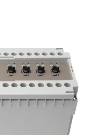
23 MULTIPLEXED AMPLIFIER SERIES MPA 41 Description Operation mode and max sensing range: Thru beam: 0-35 m Diffuse proximity: 0-2 m 230 V ac, 115 V ac, 24 V ac or 24 V dc supply voltage Manual sensitivity adjustment Adjustable on/off time delay 4 relays and/or 4 transistor individual outputs 1 relay and 1 transistor common output Switch selectable light or dark function Switch selectable long or short range Power, output and signal level indicators Screw terminals connection The MPA 41 is a 4-channel, multiplexed photoelectric amplifier, which is to be used in conjunction with 4 sets of remote transmitters LT and receivers LR, from the series 100, 110 and 120. The 4 channels operate independently of each other with their own set of remote transmitter and receiver. The multiplexing function ensures that optical cross talk between channels is prevented. The series offers a choice between 4 individual relays and/or 4 individual NPN/PNP transistor outputs, or 1 common relay and 1 common transistor output which features an adjustable 0-10 sec on/off time delay. This amplifier series offers manual sensitivity adjustment for each individual channel via integral potentiometers located on the front panel of the amplifier. Light or dark function and long or short range are switch selectable for each individual channel. Technical Data MPA 41 A MPA 41 B MPA 41 C MPA 41 D Supply voltage 24 V dc, 24 V ac, 115 V ac or 230 V ac Voltage tolerance +/ 15 % Current consumption Max. 6,5 VA Output 1 open / 1 close, 250 V ac / 3 A, 120 V ac / 5 A 40 ma / 30 V dc Green LED Red LED Signal level indicator Green LED LR sensor failure indicator LT sensor failure indicator Sensor monitor LED drive Hysteresis Approx. 35 % Operation frequency Short range 14 Hz 25 Hz Long range 8 Hz 17 Hz Short range 20 Hz 50 Hz Long range 10 Hz 25 Hz Short range 35 ms / 35 ms 20 ms / 20 ms Response time t / t Long range 60 ms / 60 ms 30 ms / 30 ms Short range 25 ms / 25 ms 10 ms / 10 ms Long range 50 ms / 50 ms 20 ms / 20 ms Delay t ON / t OFF 0 10 sec, adjustable 0 10 sec, adjustable Housing material Noryl Environmental Data Temperature, operation 10 to +50 ºC Temperature, storage 40 to +80 ºC Sealing class IP 30 Approvals abd REMOTE PHOTOELECTRIC SYSTEMS I 37
24 MPA 41 MULTIPLEXED AMPLIFIER SERIES Available Types Model MPA 41 A MPA 41 B On/Off delay MPA 41 C MPA 41 D On/Off delay Connection Screw terminals Supply Voltage 24 V dc 24 V ac 115 V ac 230 V ac Output Order Reference 4 individual NPN/PNP MPA 41 A 603 MPA 41 A 602 MPA 41 A 601 MPA 41 A individual relays and 4 individual NPN/PNP MPA 41 A 703 MPA 41 A 702 MPA 41 A 701 MPA 41 A common relay and 1 common NPN/PNP MPA 41 B 703 MPA 41 B 702 MPA 41 B 701 MPA 41 B individual NPN/PNP MPA 41 C 603 MPA 41 C 602 MPA 41 C 601 MPA 41 C individual relays and 4 individual NPN/PNP MPA 41 C 703 MPA 41 C 702 MPA 41 C 701 MPA 41 C common relay and 1 common NPN/PNP MPA 41 D 703 MPA 41 D 702 MPA 41 D 701 MPA 41 D 700 Note: Remote sensors to be ordered separately. Applicable Remote Sensors and Ranges Thru Beam Diffuse Proximity Series Short range Long range Short range Long range MPA 41 A/B m 8 m 0,4 m 0,6 m m 18 m 0,7 m 1,3 m m 35 m 1,3 m 2 m MPA 41 C/D m 4 m 0,2 m 0,4 m m 9 m 0,4 m 0,7 m m 18 m 0,7 m 1,3 m Wiring Diagrams Connect loads to + for NPN output or Connect loads to - for PNP output Power Supply Load Supply Load CH4 Load CH3 Load CH2 Load CH1 + P/N CH1 P/N CH2 P/N CH3 P/N CH4 P/N CH1 CH2 CH3 CH4 R R BI R R BI S Y Y S Y Y Wire Code R Red Bl Y Yellow S Shield MPA 41 A/C LT1 LT2 LT3 LT4 LR1 LR2 LR3 LR4 Connect load to + for NPN output or Connect load to - for PNP output Power Supply Load + P/N - Load Supply R BI R BI R BI R BI S Y S Y S Y S Y Wire Code R Red Bl Y Yellow S Shield MPA 41 B/D LT1 LT2 LT3 LT4 LR1 LR2 LR3 LR4 38 I REMOTE PHOTOELECTRIC SYSTEMS
25 MULTIPLEXED AMPLIFIER SERIES MPA 41 Dimensions and Descriptions channel 1 Sensitivity adjustment channel 1 Signal status indicator channel , Dark operated Light operated Channel Long range Short range This switch is not in use MPA 41 A/C (Units in mm) Common off delay Common output indicator Common on delay Common power on indicator channel 1 Sensitivity adjustment channel 1 Signal status indicator channel , Dark operated Light operated Channel Long range Short range Common output standard Common output inverted MPA 41 B/D (Units in mm) Telco reserves the right to change specifications without notice. REMOTE PHOTOELECTRIC SYSTEMS I 39

26 MULTIPLEXED AMPLIFIER SERIES MPA 81 Description Operation mode and max sensing range: Thru beam: 0-35 m Diffuse proximity: 0-2 m 230 V ac, 115 V ac, 24 V ac or 24 V dc supply voltage Manual sensitivity adjustment Adjustable on/off time delay 8 relays or 8 transistor individual outputs 1 relay and 1 transistor common output Switch selectable light or dark function Switch selectable long or short range Power, output and signal level indicators Screw terminals connection The MPA 81 is an 8-channel, multiplexed photoelectric amplifier, which is to be used in conjunction with 8 sets of remote transmitters LT and receivers LR, from the series 100, 110 and 120. The 8 channels operate independently of each other with their own set of remote transmitter and receiver. The multiplexing function ensures that optical cross talk between channels is prevented. The series offers a choice between 8 individual relays or 8 individual NPN/PNP transistor outputs, or 1 common relay and 1 common NPN/PNP transistor output which has an adjustable 0-10 sec on-off time delay. This amplifier series offers manual sensitivity adjustment for each individual channel, via integral potentiometers located on the front panel of the amplifier. Light or dark function and long or short range are switch selectable for each individual channel. Technical Data MPA 81 A MPA 81 B MPA 81 C MPA 81 D Supply voltage 24 V dc, 24 V ac, 115 V ac or 230 V ac Voltage tolerance +/ 15 % Current consumption Max. 6,5 VA Output 1 open / 1 close, 250 V ac / 3 A, 120 V ac / 5 A 40 ma / 30 V dc Green LED Red LED Signal level indicator Green LED LR sensor failure indicator LT sensor failure indicator Sensor monitor LED drive Hysteresis Approx. 35 % Operation frequency Short range 9 Hz 18 Hz Long range 5 Hz 11 Hz Short range 11 Hz 28 Hz Long range 6 Hz 14 Hz Short range 55 ms / 55 ms 28 ms / 28 ms Response time t / t Long range 100 ms / 100 ms 46 ms / 46 ms Short range 45 ms / 45 ms 18 ms / 18 ms Long range 90 ms / 90 ms 36 ms / 36 ms Delay t ON / t OFF 0 10 sec, adjustable 0 10 sec, adjustable Housing material Noryl Environmental Data Temperature, operation 10 to +50 ºC Temperature, storage 40 to +80 ºC Sealing class IP 30 Approvals abd REMOTE PHOTOELECTRIC SYSTEMS I 41
27 MPA 81 MULTIPLEXED AMPLIFIER SERIES Available Types Model MPA 81 A MPA 81 B On/Off delay MPA 81 C MPA 81 D On/Off delay Connection Screw terminals Supply Voltage 24 V dc 24 V ac 115 V ac 230 V ac Output Order Reference 8 individual relays MPA 81 A 503 MPA 81 A 502 MPA 81 A 501 MPA 81 A individual NPN/PNP MPA 81 A 603 MPA 81 A 602 MPA 81 A 601 MPA 81 A common relay and 1 common NPN/PNP MPA 81 B 703 MPA 81 B 702 MPA 81 B 701 MPA 81 B individual relays MPA 81 C 503 MPA 81 C 502 MPA 81 C 501 MPA 81 C individual NPN/PNP MPA 81 C 603 MPA 81 C 602 MPA 81 C 601 MPA 81 C common relay and 1 common NPN/PNP MPA 81 D 703 MPA 81 D 702 MPA 81 D 701 MPA 81 D 700 Note: Remote sensors to be ordered separately. Applicable Remote Sensors and Ranges Thru Beam Diffuse Proximity Series Short range Long range Short range Long range MPA 81 A/B m 8 m 0,4 m 0,6 m m 18 m 0,7 m 1,3 m m 35 m 1,3 m 2 m MPA 81 C/D m 4 m 0,2 m 0,4 m m 9 m 0,4 m 0,7 m m 18 m 0,7 m 1,3 m 42 I REMOTE PHOTOELECTRIC SYSTEMS
28 MULTIPLEXED AMPLIFIER SERIES MPA 81 Wiring Diagrams + Load supply - Connect Loads to - for PNP output or Connect Loads to + for NPN output Power supply CH1 CH2 CH3 C NC C NC C NC CH4 C NC CH5 C NC CH6 C NC CH7 C NC CH8 C NC R R BI R R BI LT7 LT LT7 LT LT1 LT2 LT3 LT4 LT5 LT6 LR1 LR2 LR3 LR4 LR5 LR6 LR7 LR8 LT1 LT2 LT3 LT4 LT5 LT6 LR1 LR2 LR3 LR4 LR5 LR6 LR7 LR8 R R BI R R BI R R BI S Y Y S Y Y S Y Y S Y Y R R BI R R BI R R BI S Y Y S Y Y S Y Y S Y Y LT1 LT2 LT3 LT4 LT5 LT6 LT7 LR1 LR2 LR3 LR4 LR5 LR6 LR7 LT1 LT2 LT3 LT4 LT5 LT6 LT7 LR1 LR2 LR3 LR4 LR5 LR6 LR7 LT8 LR8 LT8 LR8 Wire Code R Red Bl Y Yellow S Shield MPA 81 A/C 50x ( Output) Wire Code R Red Bl Y Yellow S Shield MPA 81 A/C 60x ( Output) + Load supply - Connect load to + for NPN output or Connect load to - for PNP output output Power supply C NO NC Load R R BI R R BI R R BI R R BI Y Y S Y Y Y Y S Y Y S S Wire Code R Red Bl Y Yellow S Shield LT1 LR1 LT2 LR2 LT3 LR3 LT4 LR4 LT5 LR5 LT6 LR6 LT7 LR7 LT8 LR8 MPA 81 B/D REMOTE PHOTOELECTRIC SYSTEMS I 43
29 MULTIPLEXED AMPLIFIER SERIES MPA 81 Dimensions and Descriptions channel 1 Sensitivity adjustment channel 1 Signal status indicator channel , Dark operated Light operated Channel Long range Short range This switch is not in use MPA 81 A/C (Units in mm) Common off delay Common output indicator Common on delay Common power on indicator channel 1 Sensitivity adjustment channel 1 Signal status indicator channel , CH1 CH2 CH3 CH4 CH5 CH6 CH7 CH8 COM COM Dark operated Long range Output std. Light operated Short range Output inverted MPA 81 B/D (Units in mm) Telco reserves the right to change specifications without notice. 44 I REMOTE PHOTOELECTRIC SYSTEMS
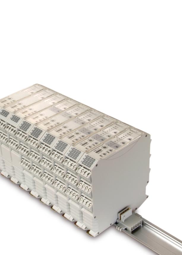
30 PHOTOELECTRIC AMPLIFIER BUS SERIES This new generation of photoelectric amplifiers, pioneers master/slave multiplexing technology in an innovative and flexible modular design. It challenges all conventional thinking on how a photoelectric system should function and with a versatile design and wide range of unique features it promises more flexibility then ever thought imaginable. Above all, it can proudly be labelled with the performance heritage that Telco has become renowned for over the past 25 years.
31
32 PHOTOELECTRIC AMPLIFIER BUS SERIES PAB 10 Description Operation mode and max sensing range: Thru beam: 0-70 m Diffuse proximity: 0-4 m V dc and 24 V ac supply voltage Manual sensitivity adjustment Sensor LED-drive Automatic sensor test Adjustable on/off time delay 1 relay or 1 transistor output Switch selectable light or dark function Switch selectable long or short range Test input Power, output, alarm, signal level and master/slave address indicators Alarm output Removable connectors DIN rail mounting The PAB 10 is a 1-channel photoelectric amplifier, which is to be used in conjunction with a set of remote transmitter LT and receiver LR from the series 100, 110 and 120. This amplifier series offers manual sensitivity adjustment via an integral potentiometer located on the front panel of the amplifier. Output can be selected from either a relay or transistor output, with an adjustable 0-10 sec on/off time delay. Light or dark function and long or short range are switch selectable. The amplifier can be connected together with up to 9 amplifiers, from the PAB series, to form a modular master/slave system. The amplifiers are connected via a rail bus connector positioned on the DIN rail. The bus connection enables the channels of all the amplifiers to be multiplexed, which ensures that optical cross talk between channels is prevented. The bus connection enables communication between the amplifiers, which allows a common output from the amplifiers and a common power supply to the amplifiers in the bus connection. The amplifier offers a test input, which is used for either disabling or enabling the transmitting power temporarily for test purposes. The amplifier includes an alarm output, which is used to indicate if the signal level is insufficient or if a sensor is faulty. The sensor LED drive powers the optional monitor LEDs available on the remote sensors output (LT) and power (LR). Technical Data Supply voltage V dc or 24 V ac Voltage tolerance ac +/ 10 % Current consumption Max. 1,7 W Output 250 V ac / 3 A, 120 V ac / 5A 30 V dc / 100 ma Green LED Yellow LED Signal level indicator Green LED Alarm indicator Red / yellow LED LR sensor failure indicator Yellow LED LT sensor failure indicator Red LED Master/slave address indicator Green / orange LED Sensor monitor LED drive Green monitor LED on receiver indicates Power ON Yellow monitor LED on the transmitter indicates PAB output activated Hysteresis Approx. 35 % Short range 21 Hz Operation frequency Long range 12 Hz Short range 42 Hz Long range 17 Hz Short range 27 ms / 20 ms Response time t ON / t OFF Long range 45 ms / 38 ms Short range 12 ms / 12 ms Long range 30 ms / 30 ms Delay t ON / t OFF 0 10 sec, adjustable Housing material Polyamide REMOTE PHOTOELECTRIC SYSTEMS I 49
33 PAB 10 PHOTOELECTRIC AMPLIFIER BUS SERIES Environmental Data Temperature, operation 10 to +50 ºC Temperature, storage 40 to +80 ºC Sealing class IP 40 Approvals a Available Types Model Connection Supply Voltage V dc / 24 V ac Output Order Reference 1 individual relay PAB 10 A 009 PAB 10 On/Off delay Screw terminals 1 individual NPN PAB 10 A individual PNP PAB 10 A 209 Note: Remote sensors and bus rail connector to be ordered separately. Applicable Remote Sensors and Ranges Thru Beam Diffuse Proximity Series Mode Short range Long range Short range Long range 100 Single 6 m 18 m 0,5 m 1,1 m Bus Modular 4 m 12 m 0,4 m 0,8 m 110 Single 13 m 40 m 0,9 m 2 m Bus Modular 9 m 27 m 0,7 m 1,7 m 120 Single 23 m 70 m 1,7 m 4 m Bus Modular 16 m 47 m 1,2 m 2,6 m Response Times in Bus Connection Short range Long range Short range Long range Response time t ON 6 ms x (N + 1) + 15 ms 15 ms x (N + 1) + 15 ms 6 ms x (N + 1) 15 ms x (N + 1) t OFF 6 ms x (N + 1) + 8 ms 15 ms x (N + 1) + 8 ms 6 ms x (N + 1) 15 ms x (N + 1) Operation frequency 83 Hz / (N + 2,9) 33 Hz / (N + 1,8) 83 Hz / (N + 1) 33 Hz / (N + 1) Note: N is equal to the total number of channels connected in the bus connection. Wiring Diagrams A D A D A D LT LR Red Shield Yellow Alarm load Supply ac / dc Test LT LR Red Shield Yellow Alarm load Supply ac / dc Test LT LR Red Shield Yellow Alarm load Supply ac / dc Test E C NC NO Ch1 Ch1 E Load Ch1 E Load output NPN output PNP output 50 I REMOTE PHOTOELECTRIC SYSTEMS
34 PHOTOELECTRIC AMPLIFIER BUS SERIES PAB 10 Dimensions and Descriptions 22,5 4,3 A Master/slave indicator Signal level indicator Alarm indicator 1 M/S Sensitivity adjustment Master/slave selector Master M Slave 1-9 Long/short switch Light/dark switch Common/individual output switch Bus/single mode switch M B S On delay adjustment Off delay adjustment 108 D E (Units in mm) Telco reserves the right to change specifications without notice. REMOTE PHOTOELECTRIC SYSTEMS I 51
35 PHOTOELECTRIC AMPLIFIER BUS SERIES PAB 20 Description Operation mode and max sensing range: Thru beam: 0-47 m Diffuse proximity: 0-2,6 m V dc and 24 V ac supply voltage Manual sensitivity adjustment Sensor LED-drive Automatic sensor test Adjustable on/off time delay 2 relay or 2 transistor outputs Switch selectable light or dark function Switch selectable long or short range Test input Power, output, alarm, signal level and master/slave address indicators Alarm output Removable connectors DIN rail mounting The PAB 20 is a 2-channel, multiplexed, photoelectric amplifier, which is to be used in conjunction with 2 sets of remote transmitters LT and receivers LR from the series 100, 110 and 120. The 2 channels operate independently of each other with their own set of remote transmitter and receiver. The multiplexing function ensures that optical cross talk between channels is prevented. This amplifier series offers manual sensitivity adjustment, for each individual channel, via an integral potentiometer located on the front panel of the amplifier. The series offers a choice between 2 individual relay or 2 individual transistor outputs, with an adjustable 0-10 sec on/off time delay. Light or dark function and long or short range are switch selectable. The amplifier can be connected together with up to 9 amplifiers, from the PAB series, to form a modular master/slave system. The amplifiers are connected via a rail bus connector positioned on the DIN rail. The bus connection enables the channels, of all the amplifiers, to be multiplexed. The bus connection enables communication between the amplifiers, which allows a common output from the amplifiers and a common power supply to the amplifiers in the bus connection. The amplifier offers a test input, which is used for either disabling or enabling the transmitting power temporarily for test purposes. The amplifier includes an alarm output, which is used to indicate if the signal level is insufficient or if a sensor is faulty. The sensor LED drive powers the optional monitor LEDs available on the remote sensors output (LT) and power (LR). Technical Data Supply voltage V dc or 24 V ac Voltage tolerance ac +/ 10 % Current consumption Max. 2,3 W Output 250 V ac / 3 A, 120 V ac / 5A 30 V dc / 100 ma Green LED Yellow LED Signal level indicator Green LED Alarm indicator Red / yellow LED LR sensor failure indicator Yellow LED LT sensor failure indicator Red LED Master/slave address indicator Green / orange LED Sensor monitor LED drive Green monitor LED on receiver indicates Power ON Yellow monitor LED on the transmitter indicates PAB output activated Hysteresis Approx. 35 % Short range 17 Hz Operation frequency Long range 9 Hz Short range 28 Hz Long range 11 Hz Short range 33 ms / 26 ms Response time t ON / t OFF Long range 60 ms / 53 ms Short range 18 ms / 18 ms Long range 45 ms / 45 ms Delay t ON / t OFF 0 10 sec, adjustable Housing material Polyamide REMOTE PHOTOELECTRIC SYSTEMS I 53
36 PAB 20 PHOTOELECTRIC AMPLIFIER BUS SERIES Environmental Data Temperature, operation 10 to +50 ºC Temperature, storage 40 to +80 ºC Sealing class IP 40 Approvals a Available Types Model Connection Supply Voltage V dc / 24 V ac Output Order Reference 2 individual relays PAB 20 A 009 PAB 20 On/Off delay Screw terminals 2 individual NPN PAB 20 A individual PNP PAB 20 A 209 Note: Remote sensors and bus rail connector to be ordered separately. Applicable Remote Sensors and Ranges Thru Beam Diffuse Proximity Series Short range Long range Short range Long range m 12 m 0,4 m 0,8 m m 27 m 0,7 m 1,7 m m 47 m 1,2 m 2,6 m Response Times in Bus Connection Short range Long range Short range Long range Response time t ON 6 ms x (N + 1) + 15 ms 15 ms x (N + 1) + 15 ms 6 ms x (N + 1) 15 ms x (N + 1) t OFF 6 ms x (N + 1) + 8 ms 15 ms x (N + 1) + 8 ms 6 ms x (N + 1) 15 ms x (N + 1) Operation frequency 83 Hz / (N + 2,9) 33 Hz / (N + 1,8) 83 Hz / (N + 1) 33 Hz / (N + 1) Note: N is equal to the total number of channels connected in the bus connection. Wiring Diagrams A D A D A D LT1 LR1 Red Shield Yellow Alarm load Supply ac / dc Test LT1 LR1 Red Shield Yellow Alarm load Supply ac / dc Test LT1 LR1 Red Shield Yellow Alarm load Supply ac / dc Test LT2 LR2 B E C NC NO C Red Ch1 Ch2 Shield Yellow LT2 LR2 Ch1 Ch2 B E Red Load Shield Yellow LT2 LR2 Ch1 Ch2 B E Red Shield Yellow F NC NO Ch2 F F output NPN output PNP output 54 I REMOTE PHOTOELECTRIC SYSTEMS
37 PHOTOELECTRIC AMPLIFIER BUS SERIES PAB 20 Dimensions and Descriptions 22,5 4,3 B A Master/slave indicator Signal level indicator Alarm indicator 1 2 M/S Sensitivity adjustment 0 10 Master/slave selector Master M Slave 1-9 Long/short switch Light/dark switch Common/individual output switch Bus/single mode switch M B S On delay adjustment Off delay adjustment 108 D E F (Units in mm) Telco reserves the right to change specifications without notice. REMOTE PHOTOELECTRIC SYSTEMS I 55
38 PHOTOELECTRIC AMPLIFIER BUS SERIES PAB 30 Description Operation mode and max sensing range: Thru beam: 0-47 m Diffuse proximity: 0-2,6 m V dc and 24 V ac supply voltage Manual sensitivity adjustment Sensor LED-drive Automatic sensor test Adjustable on/off time delay 3 relay or 3 transistor outputs Switch selectable light or dark function Switch selectable long or short range Test input Power, output, alarm, signal level and master/slave address indicators Alarm output Removable connectors DIN rail mounting The PAB 30 is a 3-channel, multiplexed, photoelectric amplifier, which is to be used in conjunction with 3 sets of remote transmitters LT and receivers LR from the series 100, 110 and 120. The 3 channels operate independently of each other with their own set of remote transmitter and receiver. The multiplexing function ensures that optical cross talk between channels is prevented. This amplifier series offers manual sensitivity adjustment, for each individual channel, via an integral potentiometer located on the front panel of the amplifier. The series offers a choice between 3 individual relay or 3 individual transistor outputs, with an adjustable 0-10 sec on/off time delay. Light or dark function and long or short range are switch selectable. The amplifier can be connected together with up to 9 amplifiers, from the PAB series, to form a modular master/slave system. The amplifiers are connected via a rail bus connector positioned on the DIN rail. The bus connection enables the channels of all the amplifiers to be multiplexed. The bus connection enables communication between the amplifiers, which allows a common output from the amplifiers and a common power supply to the amplifiers in the bus connection. The amplifier offers a test input, which is used for either disabling or enabling the transmitting power temporarily for test purposes. The amplifier includes an alarm output, which is used to indicate if the signal level is insufficient or if a sensor is faulty. The sensor LED drive powers the optional monitor LEDs available on the remote sensors output (LT) and power (LR). Technical Data Supply voltage V dc or 24 V ac Voltage tolerance ac +/ 10 % Current consumption Max. 2,6 W Output 250 V ac / 3 A, 120 V ac / 5A 30 V dc / 100 ma Green LED Yellow LED Signal level indicator Green LED Alarm indicator Red / yellow LED LR sensor failure indicator Yellow LED LT sensor failure indicator Red LED Master/slave address indicator Green / orange LED Sensor monitor LED drive Green monitor LED on receiver indicates Power ON Yellow monitor LED on the transmitter indicates PAB output activated Hysteresis Approx. 35 % Short range 14 Hz Operation frequency Long range 7 Hz Short range 21 Hz Long range 8 Hz Short range 39 ms / 32 ms Response time t ON / t OFF Long range 75 ms / 68 ms Short range 24 ms / 24 ms Long range 60 ms / 60 ms Delay t ON / t OFF 0 10 sec, adjustable Housing material Polyamide REMOTE PHOTOELECTRIC SYSTEMS I 57
39 PAB 30 PHOTOELECTRIC AMPLIFIER BUS SERIES Environmental Data Temperature, operation 10 to +50 ºC Temperature, storage 40 to +80 ºC Sealing class IP 40 Approvals a Available Types Model Connection Supply Voltage V dc / 24 V ac Output Order Reference 3 individual relays PAB 30 A 009 PAB 30 On/Off delay Screw terminals 3 individual NPN PAB 30 A individual PNP PAB 30 A 209 Note: Remote sensors and bus rail connector to be ordered separately. Applicable Remote Sensors and Ranges Thru Beam Diffuse Proximity Series Short range Long range Short range Long range m 12 m 0,4 m 0,8 m m 27 m 0,7 m 1,7 m m 47 m 1,2 m 2,6 m Response Times in Bus Connection Short range Long range Short range Long range Response time t ON 6 ms x (N + 1) + 15 ms 15 ms x (N + 1) + 15 ms 6 ms x (N + 1) 15 ms x (N + 1) t OFF 6 ms x (N + 1) + 8 ms 15 ms x (N + 1) + 8 ms 6 ms x (N + 1) 15 ms x (N + 1) Operation frequency 83 Hz / (N + 2,9) 33 Hz / (N + 1,8) 83 Hz / (N + 1) 33 Hz / (N + 1) Note: N is equal to the total number of channels connected in the bus connection. Wiring Diagrams A D A D A D LT1 LR1 Red Shield Yellow Alarm load Supply ac / dc Test LT1 LR1 Red Shield Yellow Alarm load Supply ac / dc Test LT1 LR1 Red Shield Yellow Alarm load Supply ac / dc Test LT2 LR2 B E C NC NO C Red Ch1 Ch2/3 Shield Yellow LT2 LR2 Ch1 Ch2 Ch3 B E Red Load Shield Yellow LT2 LR2 Ch1Ch2 Ch3 B E Red Load Shield Yellow LT3 LR3 C Red Shield Yellow F NC NO NC NO Ch2 Ch3 LT3 LR3 C Red Shield Yellow F LT3 LR3 C Red Shield Yellow F output NPN output PNP output 58 I REMOTE PHOTOELECTRIC SYSTEMS
40 PHOTOELECTRIC AMPLIFIER BUS SERIES PAB 30 Dimensions and Descriptions 22,5 4,3 C B A Master/slave indicator Signal level indicator Alarm indicator 1 2 M/S Sensitivity adjustment 0 10 Master/slave selector Master M Slave 1-9 Long/short switch Light/dark switch Common/individual output switch Bus/single mode switch M B S On delay adjustment Off delay adjustment 108 D E F (Units in mm) Telco reserves the right to change specifications without notice. REMOTE PHOTOELECTRIC SYSTEMS I 59
41 POWER PACK BUS SERIES PPB 00 Description Switch mode power supply V ac supply voltage Power and overload indicators DIN rail mounting The PPB 00 is intended to be used in conjunction with the PAB series, where there is a need for AC supply voltage. This power pack supplies a 24 V dc supply to the photoelectric amplifier bus (PAB) modules connected together via a rail bus connector positioned on the DIN rail. The PPB 00 can power up to ten PAB modules connected via the bus connection. The power pack offers a shut down feature for short circuit protection, which ensures that if an external voltage is connected to a PAB module, while connected to the power pack, then the PPB 00 will shut down. This prevents a short circuit between the power pack and the external power supply. Technical Data Supply voltage V ac Voltage tolerance 15 % / + 10 % Current consumption Max. 60 VA Supply output voltage 24 V dc Output load 1,2 A Output power 29 W Green LED Overload indicator Red LED Housing material Polymide Environmental Data Temperature, operation 20 to +55 ºC Temperature, storage 40 to +80 ºC Sealing class IP 40 Approvals a Available Types Model Supply Voltage Connection V ac Order Reference PPB 00 Screw terminals PPB 00 A 909 Note: Bus connector to be ordered separately. REMOTE PHOTOELECTRIC SYSTEMS I 61
MAIN CATALOGUE MAKING SENSE OF TECHNOLOGY
 MAIN CATALOGUE MAKING SENSE OF TECHNOLOGY Making sense of technology TABLE OF CONTENTS Corporate Profile Corporate Profile 2 Telco s 5 Core Values 8 Remote Photoelectric Systems Remote Sensor Series Remote
MULTIPLEXED AMPLIFIER SERIES
 MULTIPLEXED AMPLIFIER ERIE In an industry where most products resemble each other, we have strived to make sure that Telco only resembles Telco in terms of quality, reliability, performance and ease-of-use.
suppression, insensitive to optical interference, sensor E photoelectric switch, areas Zone 2 (gas) and Zone 22 (non-conductive dust).
 and Zone 22 (non-conductive dust).") KD0_Ex_D_G_en.qxd 0.08.00 Photoelectric proximity switches BGS Photoelectric reflex switches Through-beam photoelectric switches 0:8 Uhr Seite 08 Ready-to-fit and Standardcompliant - Cat. D/G Photoelectric
KD0_Ex_D_G_en.qxd 0.08.00 Photoelectric proximity switches BGS Photoelectric reflex switches Through-beam photoelectric switches 0:8 Uhr Seite 08 Ready-to-fit and Standardcompliant - Cat. D/G Photoelectric
Photoelectrics Amplifier, µ-processor Controlled Type PAM, 2-10 Inputs/2-10 Transistor Outputs
 Photoelectrics, µ-processor Controlled Type PAM, 2-10 Inputs/2-10 Transistor Outputs µ-processor controlled unit for up to 10 sets of photoelectric sensors Up to 10 independent outputs Self-diagnostic
WLL 170 Photoelectric switches with fibre-optic cable, red light, manual sensitivity adjustment -- DC. Dimensional drawing R1.6 2-R
 WLL 0 Photoelectric switches with fibre-optic cable, red light, manual sensitivity adjustment -- DC 0... 0 mm Through-beam systems Dimensional drawing R. -R. Scanning distance 0... 0 mm. Proximity systems
Compact Sensors - S8 Series. Compact size and high performance for the most challenging detection applications
 Compact size and high performance for the most challenging detection applications Compact dimensions (14x42x25 mm) Background suppression for transparent and shiny objects High speed contrast sensor up
W 23-2: Focussing on what is essential and economic
 Product group W - BGB Photoelectric proximity switch Energ. Photoelectric proximity switch W -: Focussing on what is essential and economic Photoelectric reflex switch The indicator LEDs on the W - offer
W27-3: The all-rounder: robust, powerful, very wide range of applications
 W- Photoelectric switches BGS Photoelectric proximity switches Photoelectric reflex switches Through-beam photoelectric switches W-: The all-rounder: robust, powerful, very wide range of applications speed
Photoelectric switches WLL 170(T), fibre-optic cables LL 3: flexible solutions with fibre-optic cable systems
, fibre-optic cables LL 3: flexible solutions with fibre-optic cable systems") WLL 0(T) Photoelectric switches Photoelectric switches with fibre-optic cable Proximity mode Photoelectric switches with fibre-optic cable Through-beam mode Photoelectric switches WLL 0(T), fibre-optic
WLL 0(T) Photoelectric switches Photoelectric switches with fibre-optic cable Proximity mode Photoelectric switches with fibre-optic cable Through-beam mode Photoelectric switches WLL 0(T), fibre-optic
Photoelectric Sensors XUV Sensors with Separate Optical Heads
 The XUV series of separate optical sensing heads and amplifiers provides maximum flexibility in difficult applications. Features: M 8 x Thru beam M 8 x -- Reflex Clip-on -- Thru beam Clip-on -- Reflex
Photo-electric Amplifier ISG-A123 1-channel automatic amplifier
 Photo-electric Amplifier -channel automatic amplifier Amplifier with modulated infrared light Range up to 25 m (82 ft) Automatic Level Control (ALC) according to assembly distance and direction Test function
W 2: Sub-Miniature Photoelectric Switch Range: Super-Small and Powerful
 W Photoelectric switches Photoelectric proximity switches BGS Photoelectric proximity switches energetic, (V optics) Photoelectric reflex switches W : Sub-iniature Photoelectric Switch Range: Super-Small
V 12-2 Miniature photoelectric switches: innovations in M12 housings
 V - Photoelectric switches Photoelectric proximity switches Photoelectric reflex switches Through-beam photoelectric switches V - iniature photoelectric switches: innovations in housings The V - optic
Valve Island with Electronic I/O
 Screw in Temperature /Switch with display for ON/OFF Control Indication, monitoring, transmission and ON/OFF control in one device Extra large display Menu guided parametrisation Complete communication
V 18 Laser No frills performance: long ranges, high speeds with precision
 V 8 Laser No frills performance: long ranges, high speeds with precision VTE 8 L photoelectric proximity switches: energetic type, scr. mm (9 % remission). Additional standard features: very short response
Miniature photoelectric switches series W4-3: The efficient space savers
 iniature photoelectric switches series W-: The efficient space savers Photoelectric reflex switch with switching threshold adaptation and autocollimation. Transparent objects of all kinds can be reliably
Phone: Fax: Web: -
 PHOTOELECTRIC Tubular sensors S5 SERIEs The S5 series offers a range of plastic tubular M18 photoelectric sensors. The most varied optic functions can be chosen amongst the fixed focus or diffuse proximity
Online data sheet VT12T-2P410 V12-2 CYLINDRICAL PHOTOELECTRIC SENSORS
 Online data sheet VTT-P0 V- A B C D E F Illustration may differ Ordering information Type Part no. VTT-P0 606 Other models and accessories www.sick.com/v- H I J K L M N O P Q R S T Detailed technical data
D-LAS Series D-LAS2-LC-... Design. D-LAS Series Laser Digital Light Barriers. Product name: Transmitter: D-LAS2-LC-T.
 D-LAS Series D-LAS-LC-... - Visible laser beam (
5-pole M12 connector. Connecting cable: cab-m12/5-g-2m. LED (red) for dirt accumulation indication
 for dirt accumulation indication") D-LAS Series D-LAS-34-ED-25x2-AC-T (Glass Pane Detection) - Collimated laser beam (
D-LAS Series D-LAS-34-ED-25x2-AC-T (Glass Pane Detection) - Collimated laser beam (
WT190T: The convenient, reliable proximity switch precisely the right one for challenging applications
 W90T Photoelectric switches FGS Photoelectric proximity switch BGS Photoelectric proximity switch WT90T: The convenient, reliable proximity switch precisely the right one for challenging applications TThe
Cylindrical Photoelectric Sensor
 SERIES Cylindrical Photoelectric Amplifier Built-in Cylindrical type easily mountable with M Conforming to EMC Directive AC supply type conforms to Low Voltage Directive, too. ( ) UL Recognition M This
MLV40 Series Miniature Sensors
 MLV4 Series Miniature Sensors Diffuse Mode See page 54 Features: Adjustable sensitivity Complementary outputs Sensing Range: 5 mm Outputs: NPN, PNP Thru-Beam Mode See page 57 Rugged metal housing Compact
CZ-K Series. RGB Digital Fiberoptic Sensors. Description MAIN MENU PRODUCTS APPLICATIONS INDEX SELECTION GUIDE
 RGB Digital Fiberoptic Sensors CZ-K Series Features RGB three-light source Wide detection range of 70 ±20 mm 2.75" ±0.78" High-speed response of 300 µs Water-resistant sensor head IP-67 rated Detecting
Ultraminiature Photoelectric Switches with Self-contained Amplifier
 Ultraminiature Photoelectric Switches with Self-contained Amplifier HPJ Series Fingertip-size, Provided with a various slit attachments. (six types) Fingertip-size 22 x 11 x 8 mm (thru scan model) 30 x
PICO-AMP Miniature Remote Sensing System
 PICO-AMP Miniature Remote Sensing System MD14 Modulated Amplifer and Ultra-small Remote Sensors PICO-AMP Features Ultra-small remote sensors to fit the tightest locations Three fixed frequency selections
E2C-EDA. Proximity Sensor with Separate Amplifier Enables Easily Making Highprecision Sensitivity Settings. Ordering Information
 Authorised Distributors:Intech Systems Chennai Pvt. Ltd, Chennai-00 032 Ph: +91 44 4353 Fax: 044 4353 7 E-mail: info@intechchennai.com Website: www.intechchennai.com High Precision Positioning Inductive
ED701 General Industry Pressure Transmitter
 ED701 General Industry Pressure Transmitter Standard industrial process connections Complete range of electrical connections 4... 20 ma and Voltage outputs Accuracy: 0.1%, 0.2% and 0.4% FS Quick response
SENSORS S62. Compact Sensors - S62. The most complete universal sensor in a compact 50x50 mm housing. Sensors with red, infrared LED or LASER emission
 Compact Sensors - S6 S6 The most complete universal sensor in a compact x housing Sensors with red, infrared or LASER emission from 3 cm to m Polarized retroreflective up to 0 m Multivoltage 4-40Vac/4-60Vdc
Remote Sensor Amplifier Terminal
 9 Remote Sensor Amplifier Terminal Plug-in Sensor Amplifiers with Direct CompoBus/S Terminal Connections 1 SRT1 models support only high-speed communications systems 1 4-point terminals expand to 8 points
W 27-3: The all-rounder: robust, powerful, very wide range of applications
 Product group W - BGS Photoelectric proximity switch Photoelectric reflex switch Through-beam photoelectric switch W -: The all-rounder: robust, powerful, very wide range of applications speed of set up:
W 27-3: The all-rounder: robust, powerful, very wide range of applications
 Product group W- BGS Photoelecric proximity switch Photoelectric reflex switch Through-beam photoelectric switch W -: The all-rounder: robust, powerful, very wide range of applications speed of set up:
Digital flow ELEMENT transmitter for continuous flow measurement
 Digital flow ELEMENT transmitter for continuous flow measurement Type 8036 can be combined with... DN06 to DN65 fluidic process connection Programmable outputs : one or two transistor output(s) and single
M18 Plastic. Photoelectric Standard Sensors BOS 18KF Global
 Standard Sensors BOS 18KF with expanded product line BOS 18KF series are available with red, infrared light or with a Class 1 laser. They are configured using a potentiometer or via teach-in. The plastic
U-GAGE Q45U Long-Range Ultrasonic Sensors
 U-GAGE Q45U Long-Range Ultrasonic Sensors Piezoelectric Proximity Mode Sensors with Push Button Programming of Sensing Window Limits Bipolar Discrete Outputs Features Analog models also available Models
SICK laser competence in photoelectric switches
 Laser photoelectric switches SICK laser competence in photoelectric switches WTL Laser sensors with high beam quality at distances of up to m. WL- Best performance in a metal housing. The original proven
Digital flow ELEMENT transmitter for continuous flow measurement
 ELEMENT Transmitter Digital flow ELEMENT transmitter for continuous flow measurement Type can be combined with... PN10, DN15 to DN400 fluidic process connection Programmable outputs : one or two transistor
Conductivity Transmitter N-LF V AC
 OPERATING INSTRUCTIONS Conductivity Transmitter N-LF2000 230V AC These operating instructions apply to the following device: Article Measuring range Order number N-LF2000, Conductivity measuring device
Easy to replace. A pigtailed type sensor with connector (CY- -J), which is easy to replace, is also available. Environment resistant
, which is easy to replace, is also available. Environment resistant") EQ- VF NX PM PM MS-AJ RT-6 PX- PHOTOELECTRIC SENSORS Mounting Stand SERIES Cylindrical Photoelectric Test input PNP output Light intensity type available monitor M This sensor has an M size for convenient
EQ- VF NX PM PM MS-AJ RT-6 PX- PHOTOELECTRIC SENSORS Mounting Stand SERIES Cylindrical Photoelectric Test input PNP output Light intensity type available monitor M This sensor has an M size for convenient
FEATURES. 15 m ft. 4 m ft. 2 m ft. 100 mm in. 600 mm in. 15 m ft. 4 m ft. 2 m ft. 100 mm 3.
 273 Cylindrical Photoelectric Sensor SERIES Related Information General terms and conditions... F-3 Glossary of terms... P.1549~ guide... P.231~ General precautions... P.1552~ PHOTO PHOTO MEASURE -LS200
5-step-switch for adjustment of sensitivity (switching threshold) LED (super-bright, yellow) for switching state indication.
 LED (super-bright, yellow) for switching state indication.") D-LAS Series D-LAS-24/90-ED-(16)-AC-T (Glass Pane Detection) - Collimated laser beam (
D-LAS Series D-LAS-24/90-ED-(16)-AC-T (Glass Pane Detection) - Collimated laser beam (
A new approach to static electricity countermeasures
 Advanced intelligent Sensors NEW ELECTROSTATIC SENSOR EF-SSERIES A new approach to static electricity countermeasures Measurement of surface potentials while a production line is running Phone: 8.894.42
Product description. At a glance. IP 69K-rated cylindrical photoelectric sensors in M18 stainless steel housing Resistant to all common cleaning
 V8V Cylindrical photoelectric sensors V8 Cylindrical photoelectric sensors with foolproof touch-teach for washdown areas Product description The V8V has a chemical and pressure cleaning resistant housing
Distance-setting Photoelectric Sensor
 Distance-setting Photoelectric Sensor The Combination of the Hyper LED and Shine-proof Achieves both Ease-of-use and High Performance Hyper LED mounted. Finest pin-point beam in the industry allows detection
Laser diffuse reflection light scanner with background suppression. Dimensioned drawing
 Specifications and description HRTL 3B Dimensioned drawing We reserve the right to make changes DS_HRTL3B_en_50114049.fm en 03-2013/08 50114049 10-30 V DC 2 khz 10 400(500)mm 170(250)mm with black/white
in one housing (3). The light beam is reflected by a reflector (4). The objects are detected by interruption of the light beam.
. The light beam is reflected by a reflector (4). The objects are detected by interruption of the light beam.") This info card serves as a supplement to the main position sensors catalogue and to the individual data sheets. For further information and contact addresses please visit our homepage at www.ifm. com.
This info card serves as a supplement to the main position sensors catalogue and to the individual data sheets. For further information and contact addresses please visit our homepage at www.ifm. com.
Product description. At a glance. performance in a metal housing coating available Precise autocollimation optics. sensors
 W- Laser Small photoelectric sensors W High-performance photoelectric sensor family with laser optics Product description At a glance performance in a metal housing coating available Precise autocollimation
USER S MANUAL. EX-30 Series. Amplifier Built-in Type Threaded Miniature Photoelectric Sensor
 Amplifier Built-in Type Threaded Miniature Photoelectric Sensor EX-30 Series USER S MANUAL WUME-EX30-3 Contents 1. Cautions 3 2. Part Description 4 3. Mounting 5 3-1 Mounting the sensor 5 3-2 Installation
Photo-electric Amplifier ISG-N24 1-channel amplifier (manual gain setting)
") Photo-electric Amplifier ISG-N24 -channel amplifier (manual gain setting) Amplifier with modulated infrared Range up to 35 m (5 ft) high immunitity to ambient and interference from other barriers Sensitivity
Photo-electric Amplifier ISG-N24 -channel amplifier (manual gain setting) Amplifier with modulated infrared Range up to 35 m (5 ft) high immunitity to ambient and interference from other barriers Sensitivity
Online data sheet VTF18-4N1212 V18 CYLINDRICAL PHOTOELECTRIC SENSORS
 Online data sheet VTF8-4N V8 A B C D E F Illustration may differ Ordering information Type Part no. VTF8-4N 6080 Other models and accessories www.sick.com/v8 H I J K L M N O P R S T Detailed technical
Online data sheet WSE9LC-3P2436A00 W9L-3
 Online data sheet WSE9LC-3P2436A00 W9L-3 A B C D E F H I J K L M N O P Q R S T Ordering information Type Part no. WSE9LC-3P2436A00 1080958 Other models and accessories www.sick.com/w9l-3 Illustration may
PD30CNB25xxPS. Photoelectrics, Background suppression reflective - PointSpot. Main features. Main functions. Description
 Photoelectrics, Background suppression reflective - PointSpot Main features Miniature sensor range The visible red PointSpot light makes alignment very easy Range: 250 mm Sensitivity adjustment by potentiometer
D-LAS Series D-LAS2-... Design. D-LAS Series Laser Digital Light Barriers. Product name: Transmitter: D-LAS2-(aperture)*-T
*-T") D-LAS Series -... - Visible laser beam (
D-LAS Series -... - Visible laser beam (
PHOTOELECTRIC SENSORS. Online data sheet
 Online data sheet A B C D E F Illustration may differ Ordering information Type Part no. WTB4SL-3P6V 0585 Other models and accessories www.sick.com/w4sl-3v H I J K L M N O P R S T Detailed technical data
New industry standard sensor
 48 Low cost/mall type series New industry standard sensor Longest sensing distance in class at 2 m * ignificantly reduced dead zone Indicators visible from any angle *Red LD type, with through-beam type
HPA Series. Self-contained Photoelectric Controls with High Functions. Specifications CLICK FEATURES ORDER GUIDE. Pre-leaded type (2m lead)
") 6 HPA Series Specifications Self-contained Photoelectric Controls with Functions FEATURES Strobe Light Emission, Margin Regulation, Front Incoming Light Display, and Output Inhibit Functions Allow Sensing
6 HPA Series Specifications Self-contained Photoelectric Controls with Functions FEATURES Strobe Light Emission, Margin Regulation, Front Incoming Light Display, and Output Inhibit Functions Allow Sensing
Thru-beam Sensors. Model SM800 Series. Ideal for small object detection
 Model SM800 Series MICROSONIC Thru-beam Sensors Ideal for small object detection Extremely reliable thru-beam sensing in a smaller package and ranges up to 1016 mm (40") They are miniature in size, powerful
Leuze electronic. 3 Series. Product description
 3 Series Product description Contents: 3 Series - overview and advantages Special features of Series 3 Sensor selection table Data sheets All rights reserved, especially the rights of copying and translation.
laser sensors through-beam sensor switching output / analog output high precision repeatability
 through-beam sensors 1600 design M8x1 M12x1 M18x1 through-beam sensor operating distance 1.5m 3.0m 5.0m 60.0m recognition of smallest objects high sampling frequency up to 25kHz external adjustable laser
Label Sensor. Ordering Information. Application Example E3S-CD68/CD63. Ideal for Detecting Labels on Bottles. E3S-CD68/CD63 Label Sensor
 Ideal for Detecting Labels on Bottles Satisfies the requirements of IP67. Ensures a vibration resistance of 10 Hz to 2 khz and a shock resistance of 1,000 m/s 2 (approximately 100G). Incorporates an NPN
A finger on the pulse of time
 A finger on the pulse of time F 55 long-range compact light time-of-flight sensors Optical sensors Ultrasonic sensors Inductive sensors Capacitive sensors Vision sensors and systems The multi-talent for
Long Range Metal Body Sensor
 R Long Range Metal Body Sensor 30 m Range With Advanced Fuzzy Logic H Mutual interference protection H NPN/PNP switch selectable output H M12 plug-in connector H Meets IP67 and NEMA 4X, 6P H Vibration
Remote Sensor Amplifier Terminal
 9 Remote Sensor Amplifier Terminal Plug-in Sensor Amplifiers with Direct CompoBus/S Terminal Connections 1 SRT1 models support only high-speed communications systems 1 4-point terminals expand to 8 points
Ultrasonic sensors. Reliable on almost all surfaces. UT 20 from Page 548. UT 12 from Page 564. UT/UM 18 from Page 568
 Ultrasonic sensors Reliable on almost all surfaces UT 0 from Page 58 UT from Page 56 UT/UM 8 from Page 568 UT 0-S miniature ultrasonic sensors with soundpipe Reliable detection through the smallest of
PD30ETB20xxIS. Photoelectrics, Background Suppression reflective with IR light. Main features. Description
 Photoelectrics, Background Suppression reflective with IR light Main features Description The PD30ET... stainless steel sensors are built with high-quality materials and designed for harsh environments.
W27-3: The all-rounder: robust, powerful, very wide range of applications
 Product group W- BGS Photoelectric proximity switch Photoelectric reflex switch Through-beam photoelectric switch W-: The all-rounder: robust, powerful, very wide range of applications unwanted optical
PHOTOELECTRIC S300 MAXI SENSORS APPLICATIONS.
 PHOTOELECTRIC MAXI SENSORS sensors S300 The S300 series of advanced MAXI photoelectric sensors represents the most suitable solution for critical applications thanks to excellent performances and resistance
Distance-setting Photoelectric Sensor
 Distance-setting Photoelectric Sensor The Combination of the Hyper LED and Shine-proof Achieves both Ease-of-use andhighperformance Hyper LED mounted. Finest pin-point beam in the industry allows detection
SS-A5 SERIES SH SERIES
 395 Manually Sensitivity Set Photoelectric Sensor SS-A5 SERIES SH SERIES Amplifi er-separated General terms and conditions... P.1 Sensor selection guide...p.11~ / P.9~ Related Information SH Specifications
Fibre-optic sensors and cables
 -optic sensors and cables -optic sensors and fibre-optic cables for a wide range of applications FL 0 from Page 446 -optic sensor in miniature housing for installation in restricted spaces Simple and reliable
Amplifier-separated Manual Sensitivity Setting Photoelectric Sensor
 -separated Manual Sensitivity Setting Photoelectric Sensor Twin Adjuster Enables Delicate Sensitivity Setting Twin Adjuster Its twin adjuster enables easy optimum setting to suit the application. Twin
Contrast scanners detect the little differences
 KT /KT Contrast scanners Contrast scanners Contrast scanners detect the little differences Adjustment of the standard version is carried out manually. The contrast scanner has an integrated adjustment
Non-Ferrous-Metal-Detecting Proximity Sensor (Separate Amplifier Type)
") Non-Ferrous-Metal-Detecting Proximity Sensor (Separate Amplifier Type) ECY-SD Proximity Sensor with Separate Amplifier Unit for Detection of Non-ferrous Metals with Simple Adjustment Detects aluminum,
Non-Ferrous-Metal-Detecting Proximity Sensor (Separate Amplifier Type) ECY-SD Proximity Sensor with Separate Amplifier Unit for Detection of Non-ferrous Metals with Simple Adjustment Detects aluminum,
Photoelectric Sensor
 Photoelectric Sensor Revolutionary High-performance High-quality Sensor with Built-in Amp can be adjusted in seconds because the optical axis coincides with the mounting axis. Highly visible spot on white
W 140: Miniature Photoelectric Switch Series with Large Scanning Ranges
 W : iniature Photoelectric Switch Series with Large Scanning Ranges Photoelectric proximity switch with adjustable scanning distance and background suppression (BGS): Scanning distance = adjustable up
Type matrix of inductive sensors
 Type matrix of inductive sensors 1. 2. 3. 4. 5. 6. 7. 8. 9. 10. 11. 12. 13. 14. 15. 16. 17. 18. 19. K I N - T 1 2 N S / 0 0 4 - K L 2 Product group Housing design Output Sensing distance Options 1 K =
E L E V A T O R S ELEVATORS Impaginato_2009_UK.indd :34:14
 CROSS BEAMS LIGHT CURTAINS FOR AND AUTOMATIC DOORS WIDE RANGE OF SIZE UP TO m AND 9 CROSS BEAMS Resolution from 0 mm up to 0 mm Protection degree IP External control unit not needed Conform to EN-0 - EN9-
Operating mode. distance. 7 m Light ON Dark ON (selectable) 2 m [100 mm] (See note 1.) 100 mm (wide view)
![Operating mode. distance. 7 m Light ON Dark ON (selectable) 2 m [100 mm] (See note 1.) 100 mm (wide view)](/thumbs/83/88087955.jpg "Operating mode. distance. 7 m Light ON Dark ON (selectable) 2 m [100 mm] (See note 1.) 100 mm (wide view)") Built-in Amplifier Photoelectric Sensor E3S-A/B Revolutionary High-performance High-quality Sensor with Built-in Amplifier can be adjusted in seconds because the optical axis coincides with the mounting
Built-in Amplifier Photoelectric Sensor E3S-A/B Revolutionary High-performance High-quality Sensor with Built-in Amplifier can be adjusted in seconds because the optical axis coincides with the mounting
High Reliability Of Fiber Optic Amplifier For Convenient Mounting
 Amplifier Reliability Of Amplifier For Convenient Mounting Features speed response: Max. 0.5ms Auto (Button setting)/remote synchronization input, mutual interference protection, selfdiagnosis Reverse
Specifications. Environmental. Operating Temperature [C (F)] for TRIAC output ( ) for all others
![Specifications. Environmental. Operating Temperature [C (F)] for TRIAC output ( ) for all others](/thumbs/92/108804891.jpg "Specifications. Environmental. Operating Temperature [C (F)] for TRIAC output ( ) for all others") Specifications Environmental Line Line Green Line Analog ertifications UL Listed, SA Approved, and E Marked for all applicable directives Features S Wide selection for increased application flexibility
Specifications Environmental Line Line Green Line Analog ertifications UL Listed, SA Approved, and E Marked for all applicable directives Features S Wide selection for increased application flexibility
QL55 Series Luminescence Sensor
 Self-contained, microprocessor-based luminescence sensor Features Self-contained design in a robust, compact metal housing High sensitivity Microprocessor-controlled Senses luminescent marks, even on luminescent
LED Collimated Beam Sensor LA-300 SERIES. LED collimated beam type which is as accurate as a laser sensor, but much safer.
 99 PHOTO PHOTO LED Beam Sensor - SERIES Related Information General terms and conditions... P.1 Sensor selection guide...p.11~ / P.~ CA... P.79 ~ General precautions... P.7 Conforming to EMC Directive
Leuze electronic. Throughbeam photoelectric sensor. Dimensioned drawing. Electrical connection. Accessories: ISO 9001 IP 67
 LS 303 Throughbeam photoelectric sensor Dimensioned drawing 1 khz 7m 10-30 V DC A 2 LS l A²LS - active suppression of extraneous light l Activation input for functional testing l Complementary outputs
E3S-A/B. Built-in Amplifier Photoelectric Sensor. Ordering Information. Revolutionary High-performance High-quality Sensor with Built-in Amp
 Built-in Amplifier Photoelectric Sensor Revolutionary High-performance High-quality Sensor with Built-in Amp can be adjusted in seconds because the optical axis coincides with the mounting axis. Highly
Laser diffuse reflection light scanner with background suppression. Dimensioned drawing
 Specifications and description Laser diffuse reflection light scanner with background suppression Dimensioned drawing We reserve the right to make changes DS_HRTL3B_en.fm en 01-2010/12 50114049 10-30 V
Long Range Metal Body Sensor
 R Long Range Metal Body Sensor 30 m Range With Advanced Fuzzy Logic H Mutual interference protection H NPN/PNP switch selectable output H M12 plug-in connector H Meets IP67 and NEMA 4X, 6P H Vibration
FX-CM. HQ Color Mark Sensor. Model Number Legend SALIENT FEATURES. Sensors. Proximity. Photoelectric. Sensors
 HQ Color Mark Sensor SALIENT FEATURES 18mm ±2mm Pushbutton Teach RGB LED light source 8 Remote Memory Setting Shock Resistant casing - 50G Model Number Legend 1 2 3 4 5 1. Series 4. Output FX 2. Type CM:
Online data sheet WT260-R260 W260 PRODUCT PORTFOLIO
 Online data sheet WT60-R60 W60 A B C D E F Illustration may differ Ordering information Type Part no. WT60-R60 60097 Other models and accessories www.sick.com/w60 H I J K L M N O P Q R S T Detailed technical
V 18 Laser No frills performance: long ranges, high speeds with precision
 V 8 Laser No frills performance: long ranges, high speeds with precision VTE 8 L photoelectric proximity switches: energetic type, scr. 00 mm (90 % remission). Additional standard features: very short
W 250: Compact photoelectric switch series for a broad range of applications
 W 0 Photoelectric switches Photoelectric proximity switches, GS Photoelectric reflex switches Through-beam photoelectric switches W 0: Compact photoelectric switch series for a broad range of applications
USER S MANUAL. EX-20 Series. Amplifier Built-in Ultra-compact Type Photoelectric Sensor
 Amplifier Built-in Ultra-compact Type Photoelectric Sensor EX-20 Series USER S MANUAL WUME-EX20-3 Contens 1. Cautions 3 2. Part Description 4 3. Mounting 6 3-1 Mounting the sensor 6 3-2 Mounting to sensor
Diffuse reflection light scanner with background suppression. Dimensioned drawing. Electrical connection. see remarks!
 Dimensioned drawing 1 5mm 1-3 V D Scanner with adjustable background suppression Two switching points Individual adaptation to applications by means of programming and diagnosis software Universal sensor
LED Collimated Beam Sensor LA-300 SERIES. LED collimated beam type which is as accurate as a laser sensor, but much safer.
 99 PHOTO PHOTO LED Beam Sensor - SERIES Related Information General terms and conditions... P.1 Sensor selection guide...p.11~ / P.~ CA... P.79 ~ General precautions... P.7 Conforming to EMC Directive
General-Purpose Photoelectric Sensor
 General-Purpose Photoelectric Sensor Wide Selection of High Performance Small DC Sensors Offers Longer Sensing Distances Fast 0. msec response time for high-speed sensing Extended sensing distances up
W 23-2: Focussing on what is essential and economic
 Product group W - BGB Photoelectric proximity switch Energ. Photoelectric proximity switch W -: Focussing on what is essential and economic Photoelectric reflex switch The indicator LEDs on the W - offer
Weighing Instruments. Applications. Characteristics. DMS strain gauges (load cells), DMS amplifier
, DMS amplifier") GHM GROUP CORPORATE GHM Messtechnik GmbH Schloßstr. 6 88453 Erolzheim GERMANY Phone +49 7354 937233-76 Fax +49 7354 937233-88 Weighing System Evaluation Mounting DMS strain gauges (load cells), DMS amplifier
GHM GROUP CORPORATE GHM Messtechnik GmbH Schloßstr. 6 88453 Erolzheim GERMANY Phone +49 7354 937233-76 Fax +49 7354 937233-88 Weighing System Evaluation Mounting DMS strain gauges (load cells), DMS amplifier
W 2: Subminiature photoelectric switch series: extremely small and extremely strong
 W Photoelectric switches Photoelectric proximity switches BGS Photoelectric proximity switches energetic, (V optics) Photoelectric reflex switches W : Subminiature photoelectric switch series: extremely
SUPER RGB Sensor. Lustre Detection Sensor Head. is newly developed. CZ-V20 Series. It can detect lustre without being affected by colours CZ-V20
 NEW Digital RGB Sensors CZ-V20 Series Lustre Detection Sensor Head CZ-H2 NEW SUPER RGB Sensor Lustre Detection Sensor Head is newly developed Glossy objects Digital RGB Sensor Amplifier CZ-V20 Matt objects